Abstract
The design features of high-power ore furnaces are the transformer’s secondary winding made of 4–8 isolated splits and a busbar assembly made of the same number of paired bifilar bus tubes, spaced 20–40 mm apart. Only an arc fault (AF) can occur between paired bus tubes in such an assembly, during which the assembly with currents of 35–150 kA can be completely destructed. To protect against AFs, these bus tubes are wrapped in several layers of gluey fiberglass cloth. However, such cloth is abraded under the impact of airborne abrasive dust particles during furnace operation, and coal dust in the air creates the conditions for an AF. A new current protection with a magnetic current transformer (MCT), which prevents busbar assembly destruction, is suggested. Its design is based on the analysis of the distribution of busbar assembly magnetic fields. The choice of MCT position is justified, and parameters of its windings are determined; MCT construction and fastening are described, and a technique for reliable MCT output signal transmission under strong magnetic fields and with a specified protection threshold is suggested. These protections are currently the simplest and cheapest tool for preventing the complete destruction of an expensive busbar assembly in events of AFs during it.
1. Introduction
A high-current circuit is one of key elements of ore-thermal production [1]. It is used for transferring electrical energy from furnace transformers to furnace electrodes according to the scheme shown in Figure 1a, which includes a single-phase furnace transformer (1), busbar assembly (2), a thermal expansion compensator for the busbar assembly (3), flexible couplings (4), ore furnace electrodes (5), a wall between the furnace transformers and the furnace (6), high-voltage busbars (7), and current transformers for relay protection and measuring instruments (8). According to [1], the busbar assembly is the longest part of the high-current circuit; hence, most arc faults (AFs) occur during it.
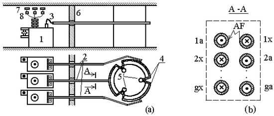
Figure 1.
(a) Arrangement of bus tubes in a busbar assembly; (b) split secondary winding of a transformer.
The voltage in a high-current circuit is almost always equal to 120–350 V [1,2]; operating currents attain 35–150 kA. Therefore, to simplify its manufacturing and reduce energy loss, the secondary winding of the furnace transformer is made of G isolated splits [1,2,3,4], and a busbar assembly is a set of water-cooled copper bus tubes, the number of pairs of which is equal to the number of splits. The diameter of these bus tubes is usually 50 or 60 mm, and the wall thickness is 14–16 mm.
A staggering arrangement of the bus tubes in a busbar assembly is the most common in ore-thermal production [2]. An example of this arrangement is shown in Figure 1b. As is seen from this figure, the busbar assembly consists of two columns of bus tubes and G rows. The direction of current in the bus tubes is designated by (×) and (●). This arrangement of current conductors in a busbar assembly is bifilar, which makes it possible to decrease the strength of a magnetic field that is produced by the currents in the busbar assembly and, hence, to reduce its inductance and the loss of energy in it [3,4,5,6]. With such an arrangement of bus tubes in a busbar assembly, AFs can occur only between bus tubes of one split, i.e., between bus tubes in one row.
In this design, the air gaps between these bus tubes act as protection against AFs. When choosing the size of these gaps, one should take into account that their decrease is accompanied by a decrease in the inductance of the busbar assembly and, hence, a decrease in energy loss [5,6], while their increase decreases the probability of AFs. According to [1,2], these air gaps are taken to be equal to 20–40 mm in a busbar assembly of an ore furnace.
However, coal dust, which is present in high concentrations in the ambient medium of a busbar assembly, can form conductive bridges between the bus tubes. As a result, an electric arc can originate between them and initiate complete destruction of the expensive busbar assembly in 1–3 s under furnace operating currents.
To prevent this destruction [1], all bus tubes in a busbar assembly are sometimes insulated by wrapping them in several layers of commercial gluey fiberglass cloth. However, there are a lot of quickly moving abrasive products of furnace fuel combustion in the ambient medium, which promotes the intensive destruction of this bus tube insulation and, hence, the occurrence of AFs.
The common mean of protection of a furnace transformer against short circuits (SCs) is an overcurrent protection, where current transformers (CTs) are used as current transducers (8 in Figure 1). However, such a protection is insensitive to AFs in the busbar assembly of the high-current circuit of an ore furnace. Therefore, an AF in a pair of bus tubes almost always results in its complete damage.
To detect AFs in the busbar assembly of an ore furnace, longitudinal differential protection with CTs can be used [7,8,9]. However, it requires a CT with a rated current of 10–30 kA to be mounted in each split of each phase of the high-current circuit. Since such CTs are very expensive and large, and the distance between the axes of the bus tubes does not exceed 100–150 mm, the design of the protection of the busbar assembly of an ore furnace based on them is of little promise.
Instead of CTs, cheaper Rogowski coils can be used for this purpose [10,11,12], which are mounted only at bus tubes with forward current in a busbar assembly. In this case, all Rogowski coils of a busbar assembly are in series where they are aiding. It is clear that the mounting of Rogowski coils at the bus tubes of a busbar assembly and the manufacture of their insulation to protect against voltage between the bus tubes is a difficult engineering task, which is complicated by the small space between the bus tubes. In addition, the electromotive force (EMF) of each Rogowski coil and the transmission of an electrical signal from these coils to the comparison unit are strongly affected by the magnetic fields that are produced by currents in the bus tubes with the reverse current in this busbar assembly, as well as by external magnetic fields that are produced by the currents in the busbars of other phases. All this casts doubt on the possibility of using Rogowski coils for AF protection of the busbar assembly of the high-current network of an ore furnace.
Protections of the busbar assembly of an ore furnace on the basis of magnetic current transformers (MCTs) can be considered a new direction [7]. An MCT is usually made as a flat coil, placed in a casing that protects it against both electrical breakdowns and mechanical damage. The MCT operation is based on measurements of the magnetic field of one or several current conductors. Therefore, for protection against AFs in the high-current circuit of an ore furnace, MCTs should be mounted in a certain way and immediately near the busbar assembly.
The sensitivity of this protection against AFs in the high-current circuit of an ore furnace depends on many factors, including the number of MCTs and the sizes of their windings, the type of arrangement of the MCTs with respect to the busbar assembly, the number of pairs of bus tubes in the busbar assembly, the position of the damaged splitting in it, the AF point in the high-current circuit, and the magnitude of external magnetic fields.
In view of the above, we suggest the following procedure for the design of AF protection of the busbar assembly of the high-current circuit of an ore furnace: First, the currents in the pairs of bus tubes of the busbar assembly are determined in the operation mode and in the case of an AF, in the circuit of an arbitrary pair of bus tubes. Then, the magnetic field of this busbar assembly is simulated on the basis of the currents in the bus tubes of the busbar assembly and their spatial arrangement. Next, the MCT position and the number of its windings are determined from the analysis of the simulation results. One should remember that the number of rows G is usually no less than four and no more than eight in busbar assemblies of ore furnaces.
2. Materials and Methods
2.1. Simulation of Currents in a Busbar Assembly in the Case of AFs
It is impossible to use known techniques for simulating currents in a busbar assembly, for example, those described in [1,2,13,14,15], because they are intended for simulation of currents in a busbar assembly without AFs.
Hence, if the resistance of the compensator, flexible couplings, systems of shoes, and contact clamps is neglected, then currents in the bus tubes of a single-phase furnace transformer with G splits in the secondary winding in the operation mode and in the case of AF can be simulated according to the circuit in Figure 2 and the mathematical model suggested in [16]. In the circuit, an AF in the gth pair of bus tubes is implemented with the use of contact K. The designations in Figure 2 are as follows:
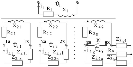
Figure 2.
Circuit of a single-phase transformer in the case of AF in the circuit of the gth split of the secondary winding. Small dots indicate "and so on”, “etc". Big dots indicate the beginning of the coil winding.
- -
- U1—the complex voltage applied to the primary winding;
- -
- I1—the complex value of the current;
- -
- R1 and jX1—active and reactive resistances in the primary winding;
- -
- Z1—impedance of the primary winding, Z1 = R1 + jX1;
- -
- —the complex values of the currents in the splits of the secondary winding;
- -
- R2.gl; R2.gn; jX2.gl; jX2.gn—active and reactive resistances of undamaged pairs of bus tubes and the load connected to them;
- -
- Z2.gl; Z2.gn—impedances of undamaged pairs of bus tubes and the load connected to them, Z2.gl = R2.gl + jX2.gl; Z2.gn = R2.gn + jX2.gn
- -
- R’2.gl and R’’2.gl; jX’2.gl and jX’’2.gl—active and reactive resistances of the sections of the damaged pair of bus tubes from the furnace transformer to the AF point and after it;
- -
- Z’2.gl and Z’’2.gl—impedances of the sections of the damaged pair of bus tubes from the furnace transformer to the AF point and after it, Z’2.gl = R’2.gl + jX’2.gl; Z’’2.gl = R’’2.gl + jX’’2.gl;
- -
- Ra—the arc resistance.
To determine the resistances of undamaged pairs of bus tubes, their damaged sections, and the busbar assembly as a whole, the technique described in [16] is used. Following this technique and taking into account the circuit in Figure 2, the currents in the splits of the secondary winding and in the bus tubes connected to them are equal in magnitude under the normal operation of the high-current circuit.
The occurrence of an electric arc in the circuit of an arbitrary pair of bus tubes is accompanied by an increase in their currents. The distribution of the currents in the damaged pair of bus tubes is shown in Figure 3a. If the resistances of the sections of the high-current circuit are assumed to be proportional to their length, then, in accordance with Figure 3, the currents in these bus tubes before the AF point and after it can be approximately calculated as
where and are the voltages at the terminals of the damaged split of the secondary winding and at the electrodes of the furnace that the damaged spilt is connected to; Za is the calculated arc resistance in the case of AF between bus tubes; and Z’2.gl = Z2.gl lAF/lhvc; Z’’2.gl = Z2.gl(lhvc − lAF)/lhvc.
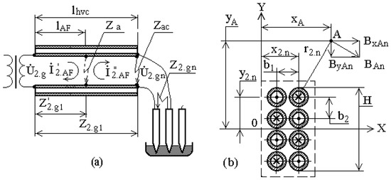
Figure 3.
Design models for simulation of the currents (a) and magnetic field (b) of bus tubes of a busbar assembly.
The arc resistance at the AF point depends on factors such as the space between the bus tubes, their insulation type, the voltage applied to them, and the ambient temperature. Hence, its accurate assessment is a difficult task. However, taking into account the diagram in Figure 3a, the arc resistance can be approximately assessed as follows: Let the arc resistance at the closing point of two bus tubes, located at the end of the busbar assembly, be equal to the impedance Z2g.n of the load of a pair of bus tubes in the form of an arc between the furnace electrodes; then, the arc resistance in I’’2.AF in Equation (1) can be calculated as
The impedance Z2.gl is usually about 1.5–2.0% of the impedance Z2g.n of the load of a pair of bus tubes in the form of an arc between the furnace electrodes [1]. Therefore, the current I’2.AF can be set equal to the double value of the current in a pair of bus tubes before an AF. Since the voltage , formed by all the three phase currents in the furnace electrode system, is approximately equal to 0.95U2.g, it is reasonable to assume the difference between I’’2.AF and I’2.AF to be insignificant.
2.2. Simulation of the Magnetic Field of a Busbar Assembly
It is impossible to use known techniques for simulating the magnetic field of a busbar assembly, for example, those described in [1,2,17,18], mainly because they are intended for simulation of the magnetic field in a busbar assembly without AFs.
Therefore, the distribution of the magnetic field of a busbar assembly of G pairs of bus tubes [19] is simulated according to the model shown in Figure 3b. In this model, G = 4. Under the assumption that the nth bus tube of this assembly is infinitely long, its diameter tends to zero, and the current in it is equal to I2.n; according to the Biot–Savart law [17,18], the components of its magnetic field at point A can be defined as
where xA and yA are the coordinates of point A; x2.n and y2.n are the coordinates of the nth bus tube; and is the distance between the nth bus tube and point A.
The horizontal and vertical components of the induction of the magnetic field of the busbar assembly are defined as
3. Results and Discussion
The simulation of the magnetic field of a busbar assembly is quite simple in, for example, Turbo BASIC [20] or a Matlab environment. The simulation of the magnetic field induction of a busbar assembly is based on Equation (4) for the horizontal Bx and vertical By components. If the busbar assembly is not damaged, then the currents in all paired bus tubes are assumed to be equal and are defined as . When an AF occurs, the current in undamaged bus tube pairs is considered to be constant, while the currents in the pair of damaged bus tubes before the AF point and after it are defined as and , respectively.
3.1. Mathematical Model Applicability
The applicability of the mathematical model suggested for the assessment of the parameters of MCTs of the protection was verified by means of comparison between the calculation and experimental results. The experiments were carried out with the high-current circuit of a EOTSNK 16000/10-K furnace transformer with 17 control steps and eight splits in the secondary winding at the busbar assembly current I2 = 30,000 A. For the busbar assembly, b1 = b2 = 0.08 m, the bus tube diameter d2.n = 0.6 m, and the current in the bus tube I2.n = I2/G = 3750 A, where I2 is the current in the busbar assembly.
The experimental results are shown in Figure 4 with dots, and the calculation results are shown with curves Bx = f(y) and By = f(y). They are derived from the currents in the bus tubes of the busbar assembly at the coordinate xA = 0.21 m in the normal operation mode during the first stage of the transformer adjustment. The comparison between the calculation and experimental results in Figure 4 shows that the error in the magnetic field components that are calculated with the suggested mathematical model is no more than 10%. Hence, this mathematical model is applicable for determining the positions of MCTs with respect to a busbar assembly, the number of windings, and their sizes.
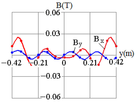
Figure 4.
Simulated components of the magnetic field of the busbar assembly in the normal operation mode.
3.2. Current Protection Based on MCT with One Winding
The positions of MCTs with respect to the busbar assembly are determined from the dependences Bx = f(y) and By = f(y), simulated for both the normal operation mode and the event of an AF in the 5th–8th splits of the secondary winding, which are shown in Figure 5, Figure 6, Figure 7 and Figure 8, respectively. The simulated dependences Bx = f(y) and By = f(y) in the region of a pair of bus tubes with the current are shown in Figure 5a, Figure 6a, Figure 7a and Figure 8a, and for the current , they are shown in Figure 5b, Figure 6b, Figure 7b and Figure 8b.
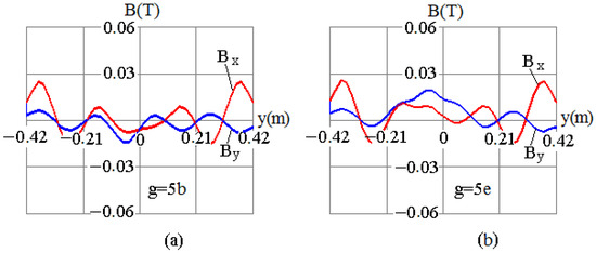
Figure 5.
Components of the magnetic field of the busbar assembly, simulated for the case of AF in the circuit of the 5th split (a) before and (b) after the AF point.
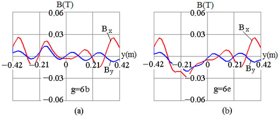
Figure 6.
Components of the magnetic field of the busbar assembly simulated for the case of AF in the circuit of the 6th split (a) before and (b) after the AF point.
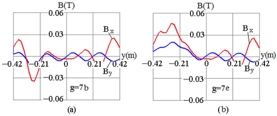
Figure 7.
Components of the magnetic field of the busbar assembly simulated for the case of AF in the circuit of the 7th split (a) before and (b) after the AF point.
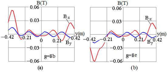
Figure 8.
Components of the magnetic field of the busbar assembly simulated for the case of AF in the circuit of the 8th split (a) before and (b) after the AF point.
The analysis of the simulated vertical component of the magnetic field of the bar assembly (Figure 4, Figure 5, Figure 6, Figure 7 and Figure 8) shows that By = f(y) = 0 at Y = 0 in the nondamaged busbar assembly, and By is nonzero in the event of an AF. This feature of the dependence By = f(y) is used in [21] to design the AF protection of the busbar assembly of a high-voltage circuit with the use of one MCT. According to [21], the MCT of this protection should be mounted at an arbitrary point A with the coordinate yA = 0. To improve the MCT outputs, it should be mounted as close to the busbar assembly as possible. The calculated values of By at point A with the coordinate xA = 0.21 m in the case of AFs in different pairs of bus tubes are given in the first row of Table 1. The analysis of these data shows that high absolute values of the induction component By of the magnetic field at the point Y = 0 in the MCT plane can be attained if the MCT is mounted at the beginning of the busbar assembly. An example of this arrangement is shown in Figure 9a, where a busbar assembly is marked by 1, an MCT is shown by 2, the MCT winding is signed by 3, its isolating casing is designated by 4, and the discriminating element of the protection is marked by 5.

Table 1.
Simulated components of the magnetic field of the busbar assembly.
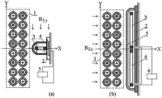
Figure 9.
(a) Position of MCT with respect to a busbar assembly; (b) diagram of AF protection of the busbar assembly.
3.3. Current Protection Based on MCT with Two Windings
The analysis of the dependence Bx = f(y) in Figure 5, Figure 6, Figure 7 and Figure 8 shows it to be symmetrical about the X axis in the nondamaged busbar assembly, while the occurrence of an AF in any pair of bus tubes disturbs this symmetry. This property of the dependence Bx = f(y) can be used for designing an AF protection. In this design, an MCT with two windings should be used, and the windings should by symmetrized about the X axis of the busbar assembly like in Figure 9b, where 1 designates the busbar assembly, 2 shows the MCT, 3 and 4 mark windings, 5 marks the isolating casing, and 6 shows the discriminating element of the protection. In this case, the value of ∆Bx, which is the difference between the mean values of the horizontal magnetic field induction component Bx in the planes of the MCT windings, is used as information about an AF.
As can be seen from Figure 5, Figure 6, Figure 7 and Figure 8, the behavior of the dependence Bx = f(y) is complex. It depends on the position of the damaged pair of bus tubes in the busbar assembly and the AF point in the high-current circuit. Therefore, the choice of the size and positions of the windings in the MCT in order to ensure an acceptable electromotive force (EMF) value at the winding outputs in the case of an AF in an arbitrary split is a quite difficult task. It can be simplified if the size of the MCT windings along the Y axis is taken to be equal to half the height H of the busbar assembly. When calculating the protection parameters, the mean magnetic flux induction in the plane of windings 3 and 4 can be found as
and their difference as
The ΔBx value in the case of AFs in different pairs of bus tubes, calculated using Equations (5) and (6) in the sections from the furnace transformer to the AF point and from the AF point to the furnace electrodes, are given in the second row of Table 1. The analysis of these data also shows that large absolute ΔBx values can be attained if the MCT is placed at the beginning of the busbar assembly.
3.4. Protection Parameters
Assuming that the mean value of the vertical component By of the magnetic field induction in the plane of the MCT winding in Figure 9a corresponds to the value given in Table 1, the actual value of the EMF in it [17,18] can be calculated as
where wMCT and QMCT are the number of turns in the MCT winding and the area of a turn in this winding.
According to the diagram in Figure 9a, winding 3 of the MCT is connected to discriminating element 5, which is a current relay with a controllable actuation threshold. The current in the relay winding is
where and Zr are the impedances of the MCT winding and of the current relay; RMCT and XMCT are the active and reactive resistances of the MCT winding.
If the MCT and the busbar assembly are perfectly manufactured and mounted, then the zero EMF is, in theory, induced in the MCT winding with their mutual arrangement. However, this is not the case in practice. It is usually impossible to accurately manufacture and mount both the busbar assembly and MCT. In addition, there is always an external magnetic field around a furnace, with the vertical induction component BδY produced by the currents in other components of the ore furnace. Therefore, the imbalance EMF Eim is induced in the MCT windings, and the imbalance current Iim flows in the discriminating element. It is quite difficult to accurately calculate the influence of these factors on Eim and Iim. Therefore, in practice, they are measured in the protection used. Based on these measurements, the protection relay threshold [8,9] is calculated as
where Iim,max is the maximal imbalance current in the load operation modes of the ore furnace; koff = 1.5 is the offset factor.
Thus, if the calculated IMCT in the protection relay circuit is lower than the protection operation current Iop in the event of an AF between a pair of bus tubes, then the protection fails to operate, that is, the protection sensitivity is insufficient. In this case, an MCT with two windings can be used for the AF protection design. In this protection, the actual EMF EMCT at the MCT output is
The current in the discriminating element in the operation mode and the protection operation current can be calculated using Equations (8) and (9). According to [8,9], this MCT type is much less sensitive to the horizontal component BδX of the external magnetic field shown in Figure 9b. Therefore, when using such an MCT, the effect of the external magnetic field can be neglected. In this regard, the imbalance current in the discriminating element circuit is lower, and the protection sensitivity is much higher.
As a winding of this MCT [22], two coils of a RP-25 intermediate relay can be used. The parameters of these coils are given in Table 2. According to our calculations, the protection sensitivity is the highest if these coils are located in currents with yA = ±0.125 m. In this case, the EMF is minimal if an AF occurs in the first (eight) and the fourth (fifth) splits: EMCT = 0.342 and −0.336 V, respectively.
Table 2.
Parameters of coils of intermediate relays.
With such windings, the maximal imbalance EMF Eim is determined through shifting an MCT along the Y axis to 2 cm from the busbar assembly. This MCT positioning accuracy can be ensured by attending personnel. In this case, the maximal imbalance EMF Eim,max = 0.156 V.
3.5. Discriminating Element of the Current Protection
Magnetic current transformers of current protections have a low output power, which makes the use of mass-produced RT-40/0.2 and RTZ-51 current relays as discriminating elements in these protections impossible [7]. Sometimes, an RZTV-1 relay can be used for this purpose. Its actuation power is significantly lower, but the MCT power can turn out to be insufficient for the actuation of this relay. In addition, if a long cable is required to connect the MCT to such a discriminating element, then it is necessary to protect this cable from EMF that has been induced in it by external magnetic fields Bδ.
This can be avoided if a cable amplifier is used to transmit information from the MCT to the discriminating element. This enables one to not only take into account the low output power of the MCT and the interference from external magnetic fields, but also to use only a two-core cable for data transmission. The diagram of current protection with an MCT and a cable amplifier is shown in Figure 10, where an MCT is marked by 1, a cable amplifier is shown by 2; a discriminating element is signed by 3, and a connecting cable is indicated by 4.
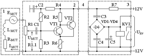
Figure 10.
Diagram of the current protection based on MCT.
The cable amplifier is small and can be placed inside the isolating casing of the MCT during its manufacturing.
According to this diagram, the MCT load is the variable resistor R1. This enables generating a required voltage UMCT at the cable input amplifier regardless of the MCT winding design and the current in the high-current circuit. This alternating voltage is supplied to the cable amplifier input through capacitor C1. The cable amplifier is two-stage and is based on transistors VT1 and VT2. The parameters of this amplifier, i.e., its linearity and gain ka, are set using resistors R2 and R6. An output signal of the cable amplifier is picked up from a voltage divider formed by this amplifier and resistor R7.
Discriminating element 3 is connected to cable amplifier 2 using connecting cable 4. In the discriminating element, the variable component of a cable amplifier output signal is supplied through coupling capacitors C3 and C4 to diode bridge VD1–VD4, where it is rectified. Then, this signal in the form of rectified voltage is applied to relay KV1 winding, which has terminals for controlling the voltage UKV. Capacitance C5 is designed to smooth out the ripple of the rectified signal.
Our experiments have shown that a cable amplifier with such a discriminating element has a linear characteristic if, at a given voltage UMCT1 set with the use of resistor R1, the relay KV1 winding voltage UKV does not exceed 3 V. Therefore, the relay KV1 actuation voltage Uact is set to be equal to 3 V.
If MCT windings are coils of an RP-25 relay with the number of turns wc = 6700 and the minimal EMCT = 0.336 V, the resistance of resistor R1 is equal to impedance ZMCT, and R1.1 = R1/2, then
In this case, the gain can be approximately estimated as
This approach to selecting the cable amplifier parameters for the selected MCT type makes it possible to successfully use this cable amplifier in AF protections for almost all ore furnace types. The cable amplifier is powered by a stabilized 12 V DC source.
In practice, the adjustment of a protection device with a cable amplifier comes down to setting the voltage
with the use of resistor R1. The relay winding voltage UKV should be equal to 2 V. This ensures reliable detection of the normal and emergency operation modes of an ore furnace.
Under an arbitrary operation mode of an ore furnace in the absence of AFs in the busbar package of a high-current circuit, the currents in all pairs of bus tubes are equal in magnitude. As a result, the voltage UMCT at the cable amplifier input is lower than 0.053 V regardless of the ore furnace load, and the relay winding voltage UKV is lower than 2 V. In this case, relay KV1 remains in its initial position, its contacts are open, and no trip signal is sent to the transformer.
If an AF occurs in the busbar assembly of the high-current circuit, the currents in all paired bus tubes remain equal except the damaged pair, where they increase approximately twofold. As a result, the voltage UMCT at the cable amplifier input exceeds 0.084 V regardless of the ore furnace load, and the relay winding voltage UKV becomes higher than the relay KV1 actuation voltage Uact. Relay KV1 actuates, its contacts close, and a trip signal is sent to the furnace transformer.
This trip enables personnel to quickly make the required repair, put the furnace transformer into operation, and successfully complete ferroalloy smelting in the furnace. In this way, it is possible to not only prevent the furnace destruction due to the impossibility of completing smelting, but also to significantly reduce the downtime of the ore furnace and the cost of recovery repairs.
4. Conclusions
- A feature of the design of high-power furnaces for ore-smelting production is the secondary winding of the furnace transformer made of 4–8 isolated splits and a busbar assembly made of the same number of pairs of bifilar bus tubes, arranged in a staggering manner with air gaps of 20–40 mm. Therefore, in such a busbar assembly, only arc faults can occur between these paired bus tubes. To protect against AFs, the bus tubes are insulated by means of wrapping them in several layers of gluey fiberglass cloth.
- The choice of MCT for the protection of a busbar assembly against AFs, where the currents attain 35–150 kA inside it, is caused by the fact that the fiberglass cloth insulation of bus tubes is destroyed during operation by the abrasive dust contained in the ambient medium. The design of current protections using CTs and Rogowski coils is a difficult and expensive engineering problem due to the need to use a large number of these devices, the high cost of CTs, and the difficulty of mounting Rogowski coils in the air gaps in a busbar assembly.
- To design an AF protection of a busbar assembly based on MCTs, the currents in its bus tubes are estimated without and during AFs. Next, the magnetic field of the busbar assembly is simulated using these currents and the spatial arrangement of the bus tubes in the assembly. From the analysis of the results, the MCT positions and the number of their windings are determined.
- Unlike the more well-known methods, the suggested technique can be used to simulate currents in a furnace transformer with a secondary winding made of G isolated splits and in a busbar assembly with the same number of pairs of bus tubes, both in the normal operation mode of the furnace transformer with the busbar assembly and in the case of an AF in an arbitrary pair of bus tubes.
- The suggested technique also enables simulating the magnetic field of a busbar assembly both in the normal operation mode of the furnace transformer with the busbar assembly and in the case of an AF in an arbitrary pair of bus tubes.
- Based on the analysis of the distribution of the magnetic fields of a busbar assembly in the normal operation mode and in the case of an AF, two simple and cheap current protections are designed on the basis of MCTs. The choice of the number of MCTs and their positions is justified; the design of these MCTs and their fastening are suggested; and techniques for the reliable transmission of the output signal and setting the response threshold are developed.
- The suggested current protections on the basis of MCTs are perhaps the only simple and cheap means that can prevent the complete damage of an expensive busbar assembly due to an AF between the bus tubes of one of its splits. The timely shutdown of a furnace transformer in the event of an AF between the bus tubes of a busbar assembly is carried out to make it possible not only to quickly disconnect the damaged pair of bus tubes and successfully complete the smelting of ferroalloy in the furnace, but also to significantly reduce the furnace downtime and the cost of repair.
- Further research will be aimed at the improvement of the suggested current protection, i.e., increasing its sensitivity by developing techniques for protection against external magnetic fields.
Author Contributions
Conceptualization, D.R. and A.N.; Data curation, O.T. and A.K.; Methodology, D.R., A.N., and E.K.; Software, O.A. and E.K.; Project administration, D.R. and A.N.; Resources, A.K. and O.A.; Supervision, A.N.; Validation, D.R. and A.N.; Visualization, O.T. and E.K. All authors have read and agreed to the published version of the manuscript.
Funding
This research was funded by the Committee of Science of the Ministry of Science and Higher Education of the Republic of Kazakhstan (grant no. AP14972775).
Data Availability Statement
All data generated or analyzed during this study are included in this published article.
Conflicts of Interest
The authors declare that they have no known competing financial interest or personal relationship that could have appeared to influence the work reported in this paper.
Nomenclature
| AF | arc fault |
| CT | current transformer |
| MCT | magnetic current transformers |
| EMF | electromotive force |
| DC | direct current |
References
- Dantsis, Y.B.; Katsevich, L.S.; Zhilov, G.M.; Mitrofanov, N.N.; Rozenberg, V.L.; Cherenkova, I.M. Short Networks and Electrical Parameters of Electric Arc Furnaces; Metallurgiya: Moscow, Russia, 1987. (In Russian) [Google Scholar]
- Dantsis, Y.B. Methods of Electrotechnical Calculations of Ore-Thermal Furnaces; Energiya: Leningrad, Russia, 1973. (In Russian) [Google Scholar]
- Kluss, F. Einfuring in die Problem des Elektrischen Lichtbogen und Widerstandofens; Springer: Berlin/Heidelberg, Germany, 1951. [Google Scholar]
- Smelyanskiy, M.Y.; Bortnichuk, N.I. Short Networks of Electric Furnaces; Gosenergoizdat: Leningrad, Russia, 1962. (In Russian) [Google Scholar]
- Romani, A. Methode rapide de calcul de l’inductance de systemes de conducteuers a forte densite de courant des fours électriques. J. Four Electr. 1956, 5, 167–175. [Google Scholar]
- Andreae, F. Formules et tables pour le calcul de l’impedance des barres omnibus pour fours électriques. J. Four Electr. 1951, 2, 35. [Google Scholar]
- Berkovich, M.A.; Molchanov, V.V.; Semenov, V.A. Fundamentals of Relay Protection Technology; Energoatomizdat: Moscow, Russia, 1984. (In Russian) [Google Scholar]
- Andreev, V. Relay Protection and Automatics of Power Supply Systems, 4th ed.; Vyssshaya Shkola: Moscow, Russia, 2008. (In Russian) [Google Scholar]
- Elmore, W.A. Protective Relaying Theory and Applications; Marcel Dekker Inc.: New York, NY, USA; Basel, Switzerland, 2004. [Google Scholar]
- Kojovic, L. Rogowski Coils Suit Relay Protection and Measurement. IEEE Comput. Appl. Power 1997, 10, 47–52. [Google Scholar] [CrossRef]
- Kojovic, L.A.; Bishop, M.T. Electrical Arc Furnace Protection System. U.S. Patent 6,810,069, 26 October 2004. [Google Scholar]
- Liu, X.; Li, R.; Liu, Z.; Jiang, R.; Guo, W.; Xing, W.; Li, G.; Deng, M. Method for Collecting Current on Low-Voltage Side of Electric Furnace Transformer and Relay Protection Device. CN Patent 102,435,813, 2 May 2012. [Google Scholar]
- Zasypkin, A.S. Relay Protection of Transformers; Energoatomizdat: Moscow, Russia, 1989. (In Russian) [Google Scholar]
- Chiesa, N.; Mork, B.A.; Hoidalen, H.K. Transformer Model for Inrush Current Calculations: Simulations, Measurements and Sensitivity Analysis. IEEE Trans. Power Deliv. 2010, 25, 2599–2608. [Google Scholar] [CrossRef]
- Yazdani-Asrami, M.; Taghipour-Gorjikolaie, M.; Mohammad Razavi, S.; Asghar Gholamian, S. A novel intelligent protection system for power transformers considering possible electrical faults, inrush current, CT saturation and over-excitation. Int. J. Electr. Power Energy Syst. 2015, 64, 1129–1140. [Google Scholar] [CrossRef]
- Novozhilov, A.N.; Novozhilov, T.A.; Rakhimberdinova, D.M. Simulations of Currents in Conditions of Electrical Damage in the Windings of a Single-Phase Furnace Transformer with a Split Secondary Winding. Russ. Electr. Eng. 2020, 91, 403–407. [Google Scholar] [CrossRef]
- Bessonov, L.A. Theoretical Foundations of Electrical Engineering; Vysshaya Shkola: Moscow, Russia, 1967. (In Russian) [Google Scholar]
- Simonyi, K. Foundations of Electrical Engineering; The Maximillan Company: New York, NY, USA, 1963. [Google Scholar]
- Novozhilov, T.A.; Novozhilov, A.N.; Rakhimberdinova, D.M. Currents in the Bus Assembly of a High-Current System for an Electrofurnace. Russ. Eng. Res. 2020, 40, 995–999. [Google Scholar] [CrossRef]
- Ellis, W.; Lodi, E. Lodi Structured Programming Using Turbo BASIC; Academic Press Inc.: London, UK, 1988; p. 337. [Google Scholar]
- Rakhimberdinova, D.M.; Novozhilov, T.A.; Novozhilov, A.N.; Kislov, A.P. Protection of the Short Network of the Ore Thermal Furnace Against Short Circuits. AIP Conf. Proc. 2021, 2337, 030011. [Google Scholar] [CrossRef]
- Kakuyevitskiy, L.I.; Smirnova, T.V. Directory of Protection and Automation Relays; Energiya: Moscow, Russia, 1972. (In Russian) [Google Scholar]
Disclaimer/Publisher’s Note: The statements, opinions and data contained in all publications are solely those of the individual author(s) and contributor(s) and not of MDPI and/or the editor(s). MDPI and/or the editor(s) disclaim responsibility for any injury to people or property resulting from any ideas, methods, instructions or products referred to in the content. |
© 2023 by the authors. Licensee MDPI, Basel, Switzerland. This article is an open access article distributed under the terms and conditions of the Creative Commons Attribution (CC BY) license (https://creativecommons.org/licenses/by/4.0/).