Article

Sulfur Loading as a Manufacturing Key Factor of Additive-Free Cathodes for Lithium-Sulfur Batteries Prepared by Composite Electroforming

Center for Electrochemical Surface Technology ZEO, Aalen University of Applied Sciences, Beethovenstr. 1, 73430 Aalen, Germany
*
Author to whom correspondence should be addressed.
Energies 2023, 16(3), 1134; https://doi.org/10.3390/en16031134
Submission received: 23 December 2022 / Revised: 12 January 2023 / Accepted: 16 January 2023 / Published: 19 January 2023
(This article belongs to the Special Issue Lithium–Sulfur Batteries: Progress and Prospects)

Abstract

:
The promised prospects of Li–S technology, especially within the energy situation of the 21st century, have sparked a renewed interest from the scientific community in the 2000s. In this context, we present our new vision for the fabrication of novel cathodes for Li–S batteries that were synthesized using the first combination of composite plating and electroforming (composite electroforming). The latter consists of electroforming the current collector foil directly in a one-step process. Simultaneously, the active material is introduced into the metal matrix by means of composite plating. Reduced technological steps, better performance and resource-saving production, combined with a potentially easier and highly efficient way of recycling electrodes, are achievements of the current method. In the present work, novel cathodes for lithium–sulfur batteries were synthesized by composite electroforming of AlSi10Mg0.4@Ni foil from a nickel sulfamate-based electrolyte with AlSi10Mg0.4 particles used as dispersoids. The composite foil is subsequently etched in order to increase the specific surface area of the aluminum alloy particles. The last manufacturing and key step of the ready-to-use cathodes for Li–S batteries is the sulfur loading, which was conducted using two different ways: by spin coating in melted sulfur at 160 °C or electrochemically from a sodium sulfide aqueous solution (Na2S(aq)). Morphological and electrochemical characterization by SEM and galvanostatic cycling, respectively, exhibited a remarkable difference in terms of the sulfur distribution and the surface morphology as well as a considerable improvement of the rate capability and cyclability for the electrochemically loaded cathode as against the spin-coated one.

1. Introduction

High specific capacity, low cost and environmental friendliness of sulfur are key advantages that made lithium/sulfur accumulators designated successors of lithium-ion technology in some application areas [1,2]. This is also reflected in the enormous increase in scientific interest in the Li–S system. In the latter, the core element of the positive electrode is elemental sulfur, bound in a suitable matrix. In this concept, the active materials, which are sulfur and lithium from the anode, can quantitatively interreact to form lithium sulfide (Li2S) [3]. Since both sulfur and lithium sulfide are non-conductors, there is a need to add conductive agents in order to confer electronic conductivity to the electrode, which sulfur and the end reaction product Li2S do not naturally possess. While carbon black was the primary material initially used, a variety of fine-tuned carbon materials are currently in use [4]. However, the main challenge here is the volume change of the solid active materials of about 80% when converting sulfur to Li2S [5]. Therefore, to guarantee the homogeneity and cohesion of these two components, as well as their adhesion to the current collector, polymer binders are incorporated [6]. The addition of electrochemically inactive and electrically non-conductive components reduces the energy, power density and efficiency of the cell. Such an issue is being addressed and solved in the present work. Within the newly developed approach, the structural and electrical connection between the cathode material and current collectors is ensured without the passive additions of binder and conductive additive. The current collector foil, which is added separately in the classical approach, is directly electroformed in a single-step process, while the active material is simultaneously introduced into the metal matrix by composite electroplating [7,8,9]. In the present synthesis method, the metal matrix of the electroformed composite serves both for electrical conduction into the external circuit (classical current collector function) and for electrical and simultaneously mechanical bonding of the active material. Unlike the classical preparation method, which incorporates nonbinding conductive agents and non-conducting binding polymers to the final electrode, the composite electroforming method can, for the first time, guarantee a synergistic optimization of the conductivity and mechanical stability. On the other hand, a substantial advantage of the composite electroforming synthesis method is the flexibility to control and precisely adjust the total film thickness based on the deposition duration. These things considered, both the achievable total proportion of active material in the layer and the proportion that is electrochemically accessible are functions of the deposition parameters such as the current density, the convection or the active material concentration in the electrolyte, as well as the type of surface functionalization. The latter strongly determines the structure of the obtained composite electrode foil, which needs to simultaneously ensure sufficient mechanical and electrical contact while leaving enough active particle surface open for later contact with the battery electrolyte. Due to the opening porosity towards the outside and the enhanced conductivity due to the exclusive usage of metal as a binding matrix, we especially suggest such composite electrodes for improving power density [10].
As previously announced, the system developed in the current study consists of composite electroformed AlSi10Mg0.4@Ni, with Ni as the current collector and metal matrix providing the electrical and mechanical bonding of the AlSi10Mg0.4 particles. Yet, the challenge here is to set suitable particle surface properties for each new type of dispersoid particle, such as the resistance to the galvanic electrolyte in use, the good wettability by the electrolyte, and the incorporation behavior into the structured metallic matrix while maintaining the highest possible active material accessibility in the subsequent battery application. The latter is usually achieved by particles that allow only partial overgrowth with the metal matrix and still guarantees sufficiently good electrical and mechanical bonding. AlSi10Mg0.4 particles are one of the most commonly used aluminum alloys for a large variety of applications [11,12,13] and due to their beneficial combination of cost and properties, namely: mechanical stability, good dispersibility, high specific area if etched, inertia after etching, lightweight, etc. [14], they have been perfect candidates to implement to our novel cathode. Therefore, despite the usage of nickel as the metallic binding matrix, the choice of aluminum alloy particles can lead to a significant weight advantage, especially since the proportion of nickel in the total cathode will be reduced and an enhancement of the energy densities, specific capacities and efficiencies, as the specific area is increased significantly. Ultimately, the final and key step in the production of our novel cathodes is the sulfur loading on the AlSi10Mg0.4 particles, already bonded to the Ni matrix and selectively etched, which increases their surface area by a factor of about 200. Due to such a very high surface area of the Al-based carrier particles, in combination with the intrinsic surface structuring resulting from the composite electroforming process, the total surface area of the cathode, especially at the preferred sites of sulfur conversion and electrocrystallization, is greatly increased.
In this paper, we carried out a detailed study of the different ways of sulfur loading. This step is as important as the composite electroforming, given its significant impact on the morphological and electrochemical properties of the final product. Two methods are to be highlighted, spin coating and electrochemical loading. The latter has proven to be the most promising one, allowing to obtain high cycling stability, reversibility, and especially an outstanding rate capability.

2. Materials and Methods

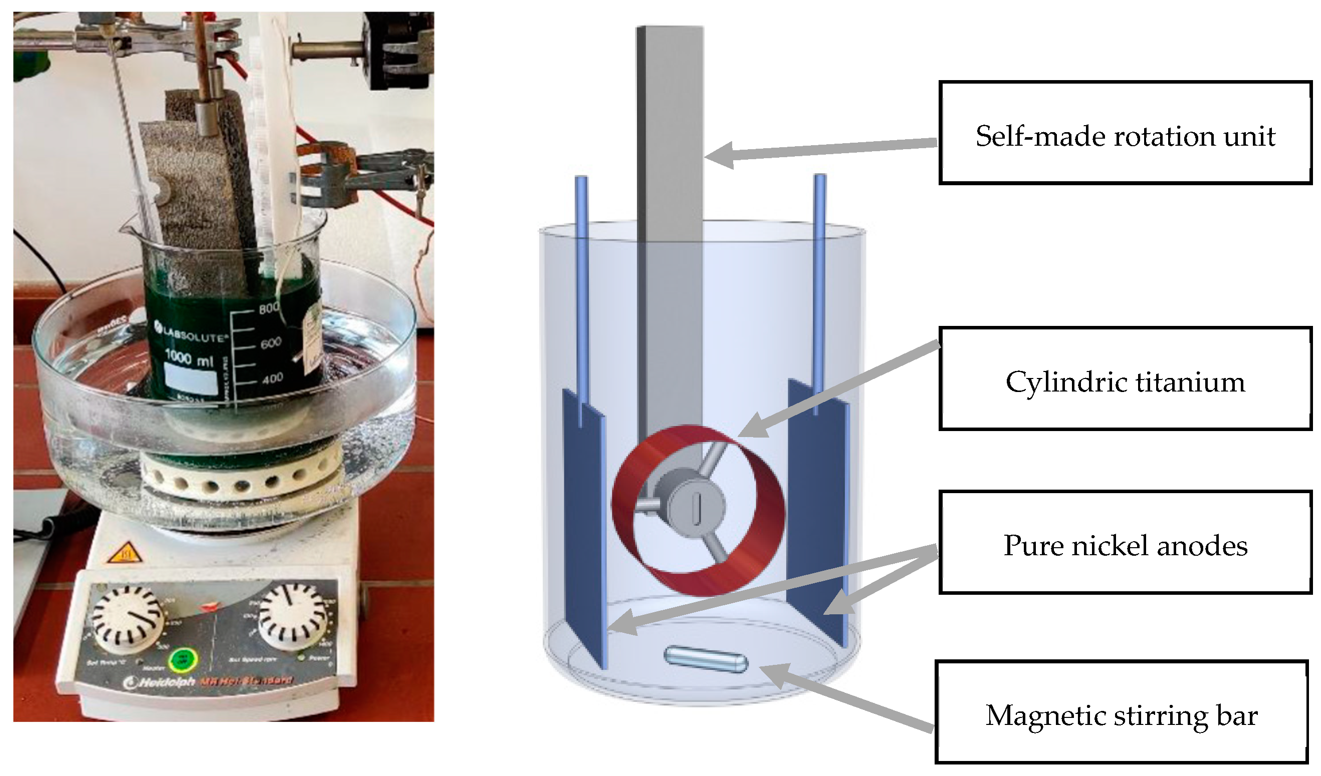
2.1. Composite Electroforming of Ni–AlSi10Mg0.4

AlSi10Mg0.4@Ni composite electroformed foil was deposited from an acidic nickel sulfamate Ni(NH2SO3)2 bath, of which the chemicals were supplied by BRW Elektrochemie GmbH&Co.KG, Balve, Germany. The basic composition of the electrolyte and the deposition parameters were held constant, as described in Table 1. The bath temperature was maintained at 50 °C, the pH at 4 and the electrolyte was magnetically stirred at a speed of 500 rpm in order to keep the particles in suspension. The AlSi10Mg0.4 (Ecka granules, Fürth, Germany) particles with a size value of d90 < 45 µm and a BET(Kr) resulting specific area of 0.2 m2/g were used in the pristine state with no further treatment.
Composite electroforming experiments were carried out using a polished titanium cylinder with a diameter of 67 mm and a length of 65 mm as a rotating cathode. The anodes were two plates of pure nickel (180 × 50 × 5 mm3) pretreated by ultrasonic degreasing (Slotoclean AK 340, Schlötter, Geislingen a. d. Steige, Germany) for 1 min and rinsed with deionized water. Subsequently, the anodes underwent a hydrochloric acid pickling (1:3) for 1 min and further rinsing with deionized water in order to obtain a uniform and clean surface. The pretreated Ni anodes were then placed opposite to each other with the vertically aligned and centered cylindric cathode, as shown in Figure 1, driven by our self-made rotation unit. A current density of 2 A/dm2 was applied for 15 min.
An electro-automatic EA-PS 9200-15T programmable laboratory power supply (Distrelec, Bremen, Germany) was used for the composite electroforming experiments by dc currents.

2.2. Etching of the AlSi10Mg0.4 on the AlSi10Mg0.4@Ni Composite Electroformed Foil

Previous investigations within our group have shown that a higher temperature of the etching solution can lead to larger specific surface areas. For this reason, a phosphoric acid solution (85% p.a., AppliChem GmbH, Darmstadt, Germany) with a 30% concentration used as an etching solution, was heated at 50 °C prior to the experiment, and the particles were then etched, keeping the temperature constant. For this purpose, the experimental setup consisted of a double-walled vessel of 1 L volume. The tempering jacket that surrounds the inner volume ensured then a uniform heat transfer. The etching solution was stirred by means of a stirring propeller with a diameter of 𝑑 = 75 mm for good etching electrolyte circulation. The propeller is attached to a shaft driven by the laboratory agitator “Hei-Torque Precision 100” (Heidolph Instruments, Schwabach, Germany). The whole setup is shown in Figure 2a. After 30 min etching time, the AlSi10Mg0.4@Ni composite electroformed foil is rinsed with deionized water.
The morphological characterization by scanning electron microscope (SEM) showed that the particles could be etched in a consistent and reproducible way (Figure 2b), regardless of Ni occupancy and partial overgrowth on the particles. The AlSi10Mg0.4 carrier particles underneath the Ni matrix were successfully and exclusively etched, stating that the Ni layer on top of the particles is not very densely packed. Accordingly, BET(Kr) measurements have proved that a specific area of up to 38.5 m2/g can be achieved for etched particles, compared to those in the pristine state with a specific area of 0.2 m2/g, giving an area increase of about 200 times after etching.

2.3. Sulfur Loading

The last manufacturing and key step of our composite electroformed cathodes for Li–S batteries is the sulfur loading, which has been conducted by either of the two approaches: spin coating or electrochemical loading.

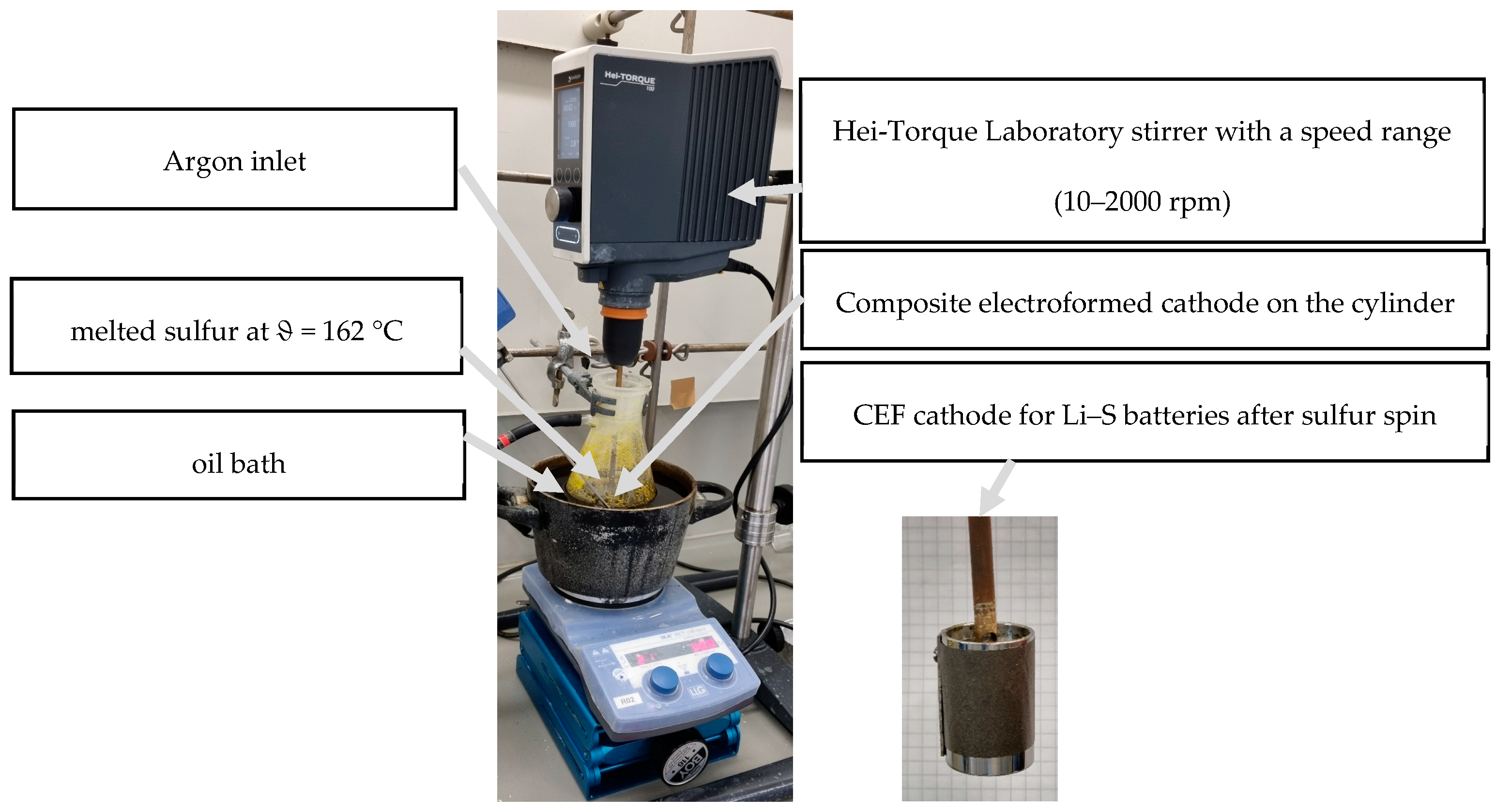
2.3.1. Sulfur Loading by Spin Coating

The first method that was implemented for sulfur loading was spin coating. For this, the AlSi10Mg0.4@Ni composite electroformed foil that was kept attached to the cylinder was introduced via the suction flask inside the melted sulfur at around 162 °C under a constant flow of argon. An oil bath was utilized to maintain the targeted temperature. The cylinder was then rotated by means of a Hei-TORQUE laboratory Precision 100 stirrer (Heidolph Instruments, Schwabach, Germany) with a speed of 1000 rpm for 2 min (Figure 3). The spinning was carried on for 40 s outside the melt to remove any sulfur excess from the surface. Subsequently, the cathode foil was carefully and immediately removed from the substrate.

2.3.2. Sulfur Loading by Electrochemical Deposition

The electrolyte that was utilized for the sulfur loading consisted of a sodium sulfide aqueous solution (Na2S(aq)) (≥98.0%, Sigma Aldrich, Steinheim, Germany) with a pH value of almost 13. As the sulfur electrolyte pH had to be adjusted and reduced to approximately 10, a volume of approx. 275 mL of sodium hydrocarbonate NaHCO3 (≥99.0%, Sigma Aldrich, Steinheim, Germany) with a concentration of 50 g/L, which also served as a conductive salt, ensuring then the ionic conductivity in the electrolyte was added gradually (Figure 4).
As a preliminary step, sulfur loading was tested on pure nickel foils as a trial prior to testing it on the composite electroformed ones. Therefore, several current densities were applied, thus resulting in a significant optically observed difference between the sulfur-loaded foils, which is to be expected as the deposition mode will change from charge transfer controlled to mass transport controlled with increasing current density which results in the formation of denser packed crystal seeds but also more diffusion controlled and therefore structured growth (Figure 5). As several current densities and loading times of the sulfur on the Ni foils have been tested, and in order to better assess the optimum current density for the electrochemical sulfur loading on the Ni substrate, experiments using a 267 mL Hull cell were carried out.
To that end, a steel plate coated with Ni was used as anode and a stainless-steel plate as cathode. As shown in Figure 5a, according to the typical Hull cell geometry, the cathode panel was placed at a defined angle with respect to the anode plane. Thus, the local current density was highest at the end closest to the anode and lowest at the other end. The two measuring ranges that were applied are from 0.05 A/dm2 to 0.5 A/dm2 at a cell current of I = 0.1 A and from 0.1 A/dm2 to 1 A/dm2 at a cell current of I = 0.2 A. Thus, the Hull cell Ni sheets showed that the adhesion in the high current density areas was less than in the lower ones (Figure 5b). Hence, by placing the panel on a Hull cell ruler, the current densities of interest for the two experiments have been found to be 0.1 or 0.2 A/dm2.
As for the previous method for sulfur loading, the AlSi10Mg0.4@Ni composite electroformed foil was kept attached to the cylinder and then immersed in the sodium sulfide aqueous electrolyte. The cathodes were two curved plates of stainless steel pretreated by ultrasonic de-greasing (Slotoclean AK 340, Schlötter, Geislingen a. d. Steige, Germany) for 1 min and rinsed with deionized water. Subsequently, the cathodes endure a hydrochloric acid pickling (1:3) for 1 min and are further rinsed with deionized water. The pretreated stainless-steel cathodes are then placed opposite to each other with the vertically aligned and centered cylindric anode, as shown in Figure 6. In this case, the rotation, as well as the electric connection of the cylinder, were insured by our self-made rotation unit.

3. Results and Discussion

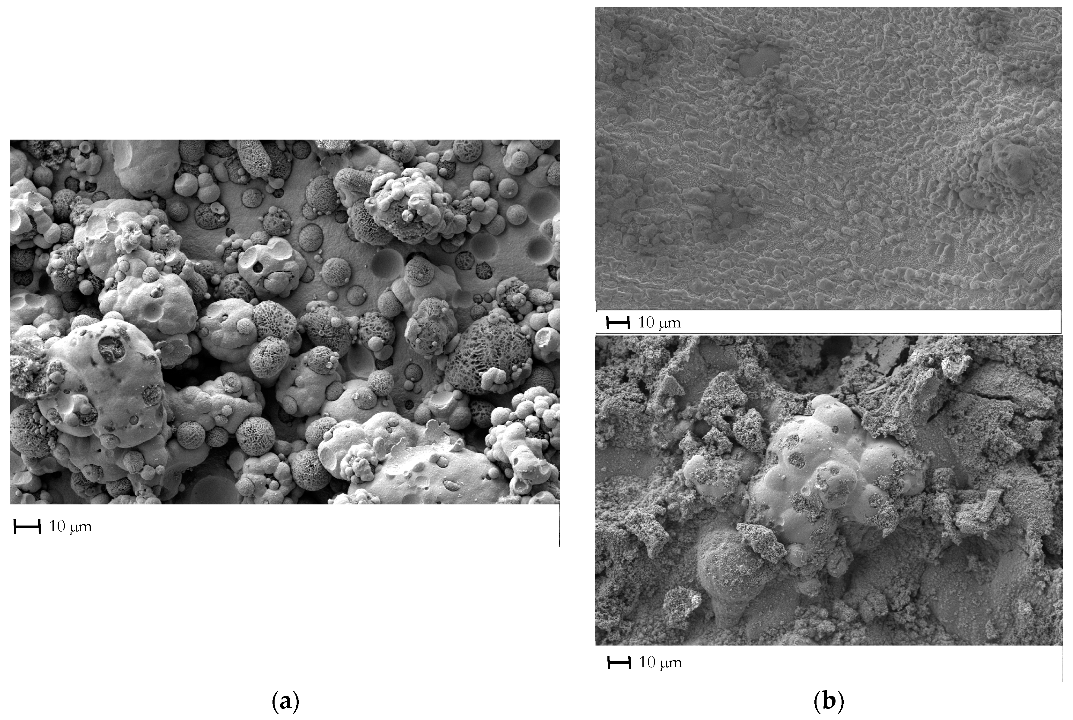
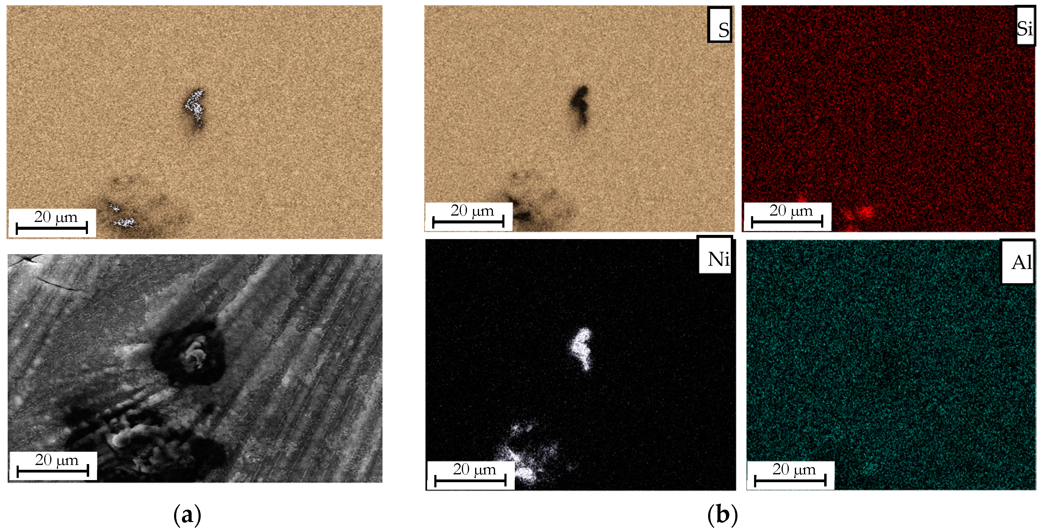
3.1. Effect of the Loading Method on the Morphological Properties of the Composite Electroformed Cathodes

Results of the morphological characterization by SEM of the AlSi10Mg0.4@Ni composite electroformed foils before and after sulfur loading either by spin coating or electrochemically are shown in Figure 7. The initial morphology of the AlSi10Mg0.4@Ni composite electroformed foil is distinctively structured. The aluminum alloy carrier particles are embedded in the surface or even in the volume of the Ni matrix (Figure 7a). On the other hand, the cathode foil after sulfur loading by spin coating presents a very different morphology (Figure 7b) since it seems that the relatively thick layer of sulfur has covered a major part of the initial materials (Ni and AlSi10Mg0.4). Moreover, the well-defined distribution of sulfur particles on the carrier particles’ surface is not visualized. Contrary to the sulfur electrochemically loaded cathode, the latter has a rather similar surface topology to that of the AlSi10Mg0.4@Ni composite electroformed foil with the incorporation of sulfur particles selectively on the aluminum alloy carrier particles (Figure 7b).
Additionally, elemental mapping of the two different cathodes was performed. Figure 8 and Figure 9 exhibit SEM images and the resulting compositional images for the spin-coated and electrochemically loaded sulfur, respectively. For the first cathode prepared by spin coating (Figure 8), the surface is indeed entirely covered by sulfur, making the detection of the other elements, such as Ni or Si, barely possible. The latter can only be detected when they are overgrowing on the composite electroformed foil surface.
For the second type of cathode, electrochemically loaded, the sulfur is loaded mainly on the particles and does not cover the whole foil surface. The detection of other elements, such as Ni or Si, is, therefore, possible (Figure 9).

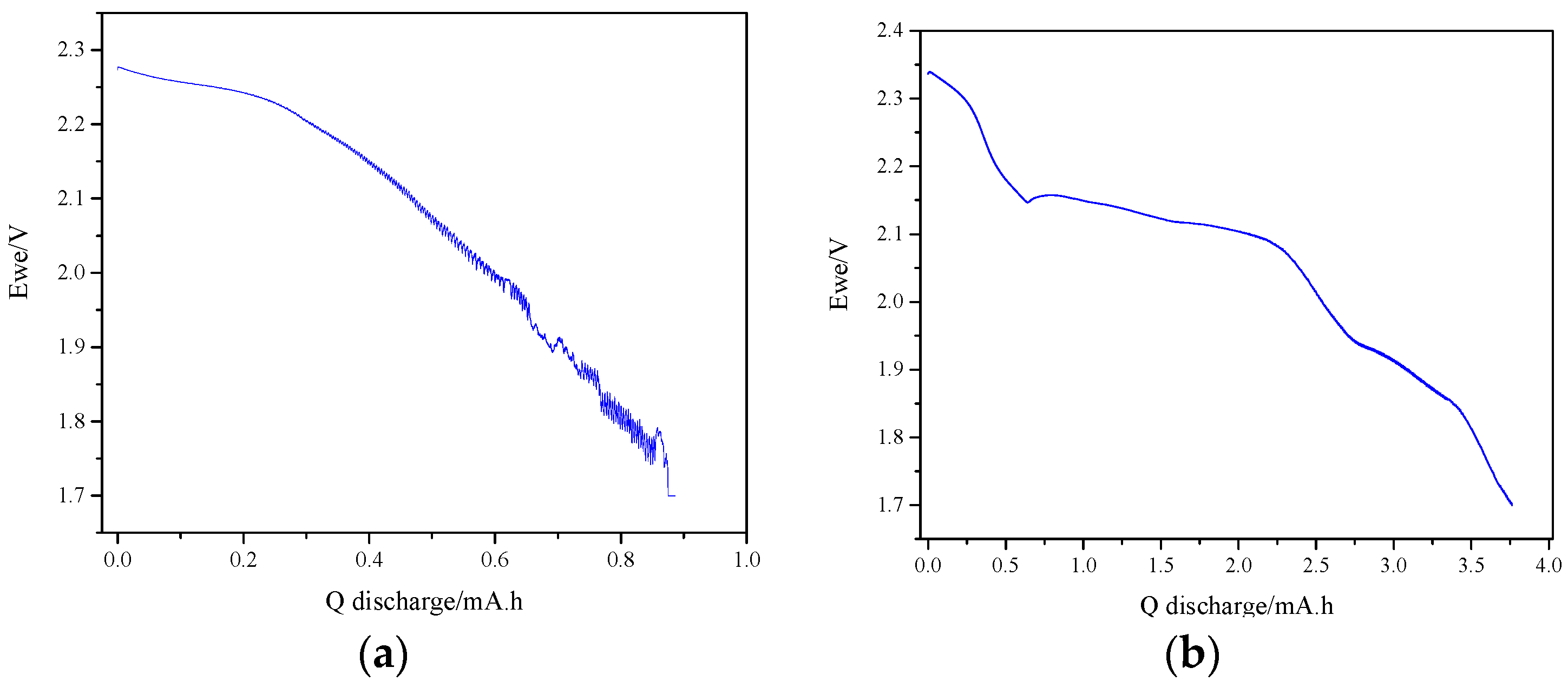
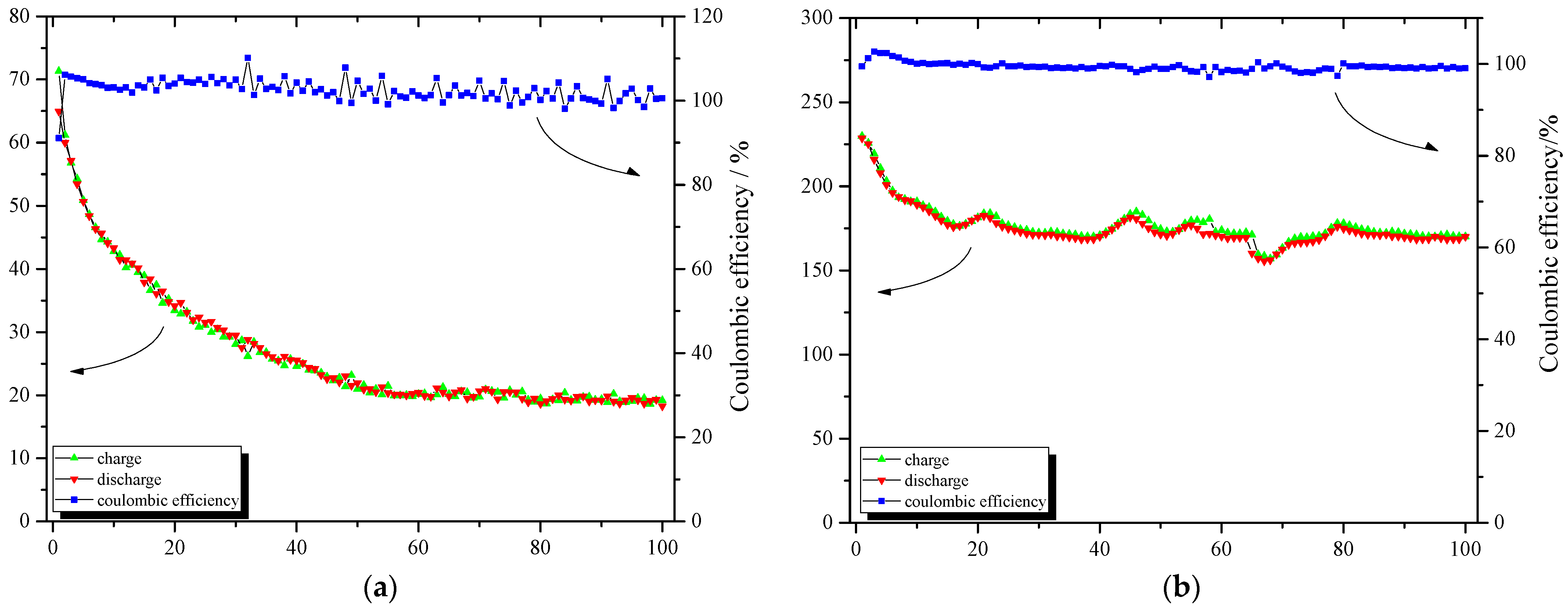
3.2. Effect of the Loading Method on the Electrochemical Performance of the Composite Electroformed Cathodes

The electrochemical characterization of the two different cathodes was achieved using half cells in a CR2032 coin cell configuration with a wave spring and a spacer. The electrolyte was composed of a mixture of dimethyl ether (DME) (99.5%, Sigma Aldrich, Steinheim, Germany) and 1,3-dioxolane (DOL) (99.8%, Sigma Aldrich, Steinheim, Germany) with a volume ratio of 50/50, to which LiTFSI (99.95%, Sigma Aldrich, Steinheim, Germany) and lithium nitrate (LiNO3) (99.99%, Sigma Aldrich, Steinheim, Germany) were added in solid form to obtain respective concentrations of 1 M and 0.5 M after dissolution. The electrolyte considered standard for Li–S batteries was stored in an argon-filled glove box (H2O < 0.1 ppm, O2 < 0.1 ppm) in a hermetically sealed bottle. The stamping of cathodes and separators with 14 mm and 16 mm diameters, respectively, was ensured using respective stamping tools (Wink Stanzwerkzeuge, Neuenhaus, Germany). Cathodes in the form of 14 mm diameter discs were cut, weighed, and stored in the argon-filled glove box (see above). The positive electrodes based on sulfur were placed in the positive cap of the coin cell. One separator (Celgard 2500, Celgard, Charlotte, NC, USA) was then placed on top of it, soaked with 15 μL of electrolyte and acting as an electrolyte reservoir. The separator was cut into a 16 mm diameter disk to cover the entire surface of the electrodes and prevent short-circuiting. A 14 mm diameter disc of metallic lithium (about 0.25 mm thick, Sigma Aldrich, Steinheim, Germany) was then placed, acting as a counter and reference electrode. A stainless-steel spacer was added to the lithium side. Finally, a stainless-steel spring was added before the negative lid to maintain the pressure and contact of the different components of the cell. The coin cell was sealed by a crimping device (MTI Corp., Richmond, CA, USA) with a force of 0.9 tons. Therefore, the first step required for all the cells before initiating their cycling is coulometric titration at a very low current of 25 µA in order to extract the maximum of the active mass and then to assess it by Faraday’s law (Figure 10). Generally, for Li–S batteries during discharge, two to three characteristic plateaus are visible [15,16,17,18], the first at approx. 2.3 V, which is commonly attributable to the reduction of solid elemental sulfur and the formation of soluble long-chain polysulfides, and the second plateau at approx. 2.1 V, related to the reduction of shorter chain polysulfides and, if the full capacity is extracted, the formation of the solid products Li2S2 and Li2S. Further reduction of high-order polysulfides (Li2Sn, n ≥ 4) to low-order polysulfides (Li2Sn, n < 4) and lithium sulfide can occur at a low-voltage plateau (<2.1 V), which was the case for the electrochemically loaded cathode.
It can be seen in Figure 10 that the coulometric titration plots of the two cathodes show a big difference either in terms of the capacity (0.89 mAh for spin-coated vs. 3.78 mAh for electrochemically loaded) or in terms of the discharge curve shape. Therefore, in the case of the sulfur spin-coated cathode, the presence of only one plateau is proof of the partial and incomplete reduction of high-order polysulfides due to the high loading of electrochemically inactive sulfur. Thereafter, the cathodes were cycled galvanostatically at a C/10 rate for 100 cycles in the potential range between 1.7 and 2.8 V vs. Li+/Li. The two cathodes delivered different capacity values. On the other hand, good cycling stability and high coulombic efficiency were observed for the electrochemically loaded sample (Figure 11a), in contrary to the spin-coated one for which the capacity was continuously fading (Figure 11b). This all explains that the spin-coated sulfur largely remained electrochemically passive while the electrochemically loaded sulfur was easier to extract electrochemically, as basically, this is just a reversal of the loading process. Hence sulfur is supposed to only deposit at electrochemically favorable spots on the surface, where consequently, it should also preferentially be reduced into the electrolyte during battery discharge.
Quantitative evaluation of the electrochemical results by coulometric titration or galvanostatic cycling revealed that the sulfur mass of the spin-coated sample was 7 mg. Thus, the sulfur loading was 4 mg/cm2. However, only 0.52 mg of active sulfur was extracted during the coulometric titration resulting in a very poor sulfur active mass ratio of only 7.4%. Hence, even with such a competitive sulfur loading of 4 mg/cm2 on the cathode, the amount of electrochemically passive sulfur remains very high. This is reflected in the specific capacity values and the capacity retention with cycling, which are very low. As for the electrochemically loaded cathode, a much better improvement in electrochemistry is to be seen. The sulfur loading, in this case, was almost the same as the spin-coated cathode, with a value of 3.9 mg/cm2. An amount of 2.3 mg of active sulfur was extracted during the coulometric titration, resulting in a higher sulfur active mass ratio of almost 38%. Then, with such a sulfur loading approach on the cathode, a quite promising and competitive capacity density per area of 2.44 mAh/cm2 was obtained [19]. The specific capacity, as well as the capacity retention with cycling, were also very promising.
Finally, in order to characterize the stress response of the electrochemically loaded cathode; which was the most promising one; to different C rates, a rate capability test was performed. Initially, the cell was cycled at a C/10 rate to extract a higher amount of active mass. Then, it was cycled at different C rates: C/5, C/2, 1 C, 2 C and even 5 C, then back to C/10. As can be seen from Figure 12, the cathode presented a progressive decrease of its specific capacity when increasing the C rate, which is expected due to the heavy buildup of overpotentials, especially mass transport derived, a typical observation for sulfur cathodes. Yet thereafter, it was able to immediately regain the initial capacity in the range of 300 mAh/g when the cell was again cycled at a C/10 rate. This is due to better accessibility to the initially inactive sulfur throughout the cycling and probably to the good structural stability of the cathode. Furthermore, this is also largely attributed to the significantly increased specific surface area [20] due to the incorporation of highly porous etched aluminum alloy particles, which lowers the real local current densities and, therefore, the charge transfer overpotential and maybe also the nucleation overpotential. On the other hand, the coulombic efficiency increased at high C rates, which can be due to the diminution of the shuttle effect resulting from polysulfides at high current densities [21,22].

4. Conclusions

The sustained and expanding interest in Li–S batteries technology has led to the development of new formulations and processes for the preparation of novel generations of electrode materials. To this end, in the present paper, we have reported our new approach for the fabrication of novel cathodes for Li–S batteries by composite electroforming.
The cathodes investigated in this study are composed of a Ni matrix, serving both as a current collector and as an electrical and mechanical binding agent for the active material, thus skipping the use of electrochemically inactive and electrically non-conductive and mechanically non-binding components commonly used in the classical approach. The composite electroformed cathodes are thereafter made up of a high percentage of Al alloy carrier particles AlSi10Mg0.4 which are etched to increase their specific area before being loaded with sulfur. This last step proved to be a key step in the preparation of our cathodes, given its important influence on the morphological and electrochemical properties of the final product. Two different methods of sulfur loading have been reported; the first one is by spin coating in melted sulfur at approx. 160 °C, and the second one is by electrochemical route using a sodium sulfide-based aqueous electrolyte (Na2S(aq)). Morphological characterization by SEM showed a great difference in terms of sulfur distribution and surface morphology between the two types of cathodes. This was reflected in their electrochemical performance. Long-term cycling by GC showed that the sulfur accessibility for the electrochemically loaded cathode was five times higher than for the spin-coated cathode, even though both had almost the same total sulfur loading (3.9 mg/cm2 and 3.96 mg/cm2, respectively). Moreover, significant differences in terms of specific capacity values, capacity retention with cycling and coulombic efficiency were observed, stating the large improvement in the electrochemical performance of the electrochemically loaded cathode compared to the spin-coated one.

Author Contributions

Conceptualization, T.S.; methodology, T.S.; software, W.E.M.; validation, W.E.M.; formal analysis, W.E.M.; investigation, W.E.M.; resources, T.S.; data curation, W.E.M.; writing—original draft preparation, W.E.M.; writing—review and editing, T.S. and W.E.M.; visualization, W.E.M. and T.S.; supervision, T.S.; project administration, W.E.M. and T.S.; funding acquisition, T.S. All authors have read and agreed to the published version of the manuscript.

Funding

This research was funded by the German Federal Ministry for Economic Affairs and Climate Action (BMWK) within the 7th Energy Research Program under grant number 03ETE026B (SolidS project).

Data Availability Statement

Not applicable.

Acknowledgments

The support of Tim Schubert from the Materials Research Institute Aalen and the Center for Electrochemical Surface Technology ZEO students and members at Aalen University of Applied Sciences is appreciated.

Conflicts of Interest

The authors declare no conflict of interest.

References

  1. Fedorková, A.; Oriňáková, R.; Čech, O.; Sedlaříková, M. New Composite Cathode Materials for Li/S Batteries: A Review. Int. J. Electrochem. Sci. 2013, 8, 10308–10319. [Google Scholar]
  2. Manthiram, A.; Fu, Y.; Chung, S.-H.; Zu, C.; Su, Y.-S. Rechargeable Lithium–Sulfur Batteries. Chem. Rev. 2014, 114, 11751–11787. [Google Scholar] [CrossRef] [PubMed]
  3. Zhang, J.; Yang, J.; Liu, Z.; Zheng, B. Interaction Mechanisms between Lithium Polysulfides/Sulfide and Small Organic Molecules. ACS Omega 2021, 6, 4995–5000. [Google Scholar] [CrossRef] [PubMed]
  4. Chen, L.; Shaw, L. Recent advances in lithium–sulfur batteries. J. Power Sources 2014, 267, 770–783. [Google Scholar] [CrossRef]
  5. Waluś, S.; Offer, G.; Hunt, I.; Patel, Y.; Stockley, T.; Williams, J.; Purkayastha, R. Volumetric expansion of Lithium-Sulfur cell during operation—Fundamental insight into applicable characteristics. Energy Storage Mater. 2018, 10, 233–245. [Google Scholar] [CrossRef]
  6. Hencz, L.; Chen, H.; Ling, H.; Wang, Y.; Lai, C.; Zhao, H.; Zhang, S. Housing Sulfur in Polymer Composite Frameworks for Li–S Batteries. Nano-Micro Lett. 2019, 11, 17. [Google Scholar] [CrossRef] [PubMed] [Green Version]
  7. Sörgel, T.; Meinhard, S.; Sörgel, Ş. Film Composite Material. EP 3114721, 16 January 2019. [Google Scholar]
  8. Erhardt, C.; Sörgel, Ş.; Meinhard, S.; Sörgel, T. Proof of concept for a novel, binder-free and conducting carbon-free sulfur battery cathode: Composite electroformation of copper foil with incorporated polythiophene wrapped sulfur particles. J. Power Sources 2015, 296, 70–77. [Google Scholar] [CrossRef]
  9. Sörgel, T.; Meyer, J. Chemische und elektrochemische Dispersionsbeschichtung. WOMag 2013, 9, 24–33. [Google Scholar]
  10. Kang, N.; Lin, Y.; Yang, L.; Lu, D.; Xiao, J.; Qi, Y.; Cai, M. Cathode porosity is a missing key parameter to optimize lithium-sulfur battery energy density. Nat. Commun. 2019, 10, 4597–4607. [Google Scholar] [CrossRef] [PubMed] [Green Version]
  11. Park, D.; Choi, S.; Kim, J.; Lee, J. Cryogenic mechanical behavior of 5000- and 6000-series aluminum alloys: Issues on application to offshore plants. Cryogenics 2015, 68, 44–58. [Google Scholar] [CrossRef]
  12. Lech-Grega, M.; Szymañski, W.; Płonka, B.; Boczkal, S.; Gawlik, M.; Bigaj, M.; Korczak, P. The Structure and Properties of Wrought Aluminium Alloys Series 6xxx with Vanadium for Automotive Industry. In Light Metals 2013; Springer: Cham, Switzerland, 2013; pp. 527–532. [Google Scholar]
  13. Steier, V.; Ashiuchi, E.; Reißig, L.; Araújo, J. Effect of a deep cryogenic treatment on wear and microstructure of a 6101-aluminum alloy. Adv. Mater. Sci. Eng. 2016, 10, 1155–1167. [Google Scholar]
  14. Fujii, H.; Oka, T. Development of Lightweight Forged Piston Material by Optimizing Size of Needle-type Intermetallic Compound. SAE Int. J. Mater. 2009, 1, 450–458. [Google Scholar] [CrossRef]
  15. Jayaprakash, N.; Shen, J.; Moganty, S.; Corona, A.; Archer, L. Porous Hollow Carbon@Sulfur Composites for High-Power Lithium–Sulfur Batteries. Angew. Chem. Int. Ed. 2011, 50, 5904–5908. [Google Scholar] [CrossRef] [PubMed]
  16. Ji, L.; Rao, M.; Zheng, H.; Zhang, L.; Li, Y.; Duan, W.; Guo, J.; Cairns, E.; Zhang, Y. Graphene Oxide as a Sulfur Immobilizer in High Performance Lithium/Sulfur Cells. J. Am. Chem. Soc. 2011, 133, 18522–18525. [Google Scholar] [CrossRef] [PubMed]
  17. Yamin, H.; Peled, E. Electrochemistry of a nonaqueous lithium/sulfur cell. J. Power Sources 1983, 9, 281–287. [Google Scholar] [CrossRef]
  18. Pan, Z.; Brett, D.; He, G.; Parkin, I. Progress and Perspectives of Organosulfur for Lithium–Sulfur Batteries. Adv. Energy Mater. 2022, 12, 2103483. [Google Scholar] [CrossRef]
  19. Lu, S.; Chen, Y.; Wu, X.; Wang, Z.; Lingyuan, L.; Qin, W.; Jiang, L. Binder-free cathodes based on sulfur–carbon nanofibers composites for lithium–sulfur batteries. RSC Adv. 2014, 4, 18052. [Google Scholar] [CrossRef]
  20. Ding, K.; Liu, Q.; Bu, Y.; Meng, K.; Wang, W.; Yuan, D.; Wang, Y. High surface area porous polymer frameworks: Potential host material for lithium-sulfur batteries. J. Alloys Compd. 2016, 657, 626–630. [Google Scholar] [CrossRef]
  21. Brückner, J.; Thieme, S.; Grossmann, H.; Dörfler, S.; Althues, H.; Kaskel, S. Lithium–sulfur batteries: Influence of C-rate, amount of electrolyte and sulfur loading on cycle performance. J. Power Sources 2014, 268, 82–87. [Google Scholar] [CrossRef]
  22. Sörgel, Ş.; Kesten, O.; Wengel, A.; Sörgel, T. Nickel/sulfur composite electroplated nickel foams for the use as 3D cathode in lithium/sulfur batteries—A proof of concept. Energy Storage Mater. 2018, 10, 223–232. [Google Scholar] [CrossRef]
Figure 1. Experimental setup and its schematic representation for composite electroforming process.
Energies 16 01134 g001
Figure 2. Etching of the AlSi10Mg0.4@Ni composite electroformed foil (a) picture of the required experimental setup (b) SEM images of the AlSi10Mg0.4@Ni foil before (up) and after (down) etching.
Energies 16 01134 g002
Figure 3. Experimental setup of the sulfur loading by spin coating approach.
Energies 16 01134 g003
Figure 4. Evolution of the Na2S(aq) pH values as a function of NaHCO3(aq) added volume.
Energies 16 01134 g004
Figure 5. Electrochemical sulfur loading experiment using (a) a 267 mL Hull cell and (b) the resulting coatings on the Ni panels using currents of 0.1 A (up) and 0.2 A (down).
Energies 16 01134 g005
Figure 6. Experimental setup of the electrochemical sulfur loading approach.
Energies 16 01134 g006
Figure 7. SEM images of (a) composite electroformed and etched AlSi10Mg0.4@Ni foil and (b) composite electroformed, etched and sulfur-loaded foil by spin coating (up) or electrochemically (down).
Energies 16 01134 g007
Figure 8. (a) SEM image and elemental mapping of a composite electroformed, etched and sulfur-loaded foil by spin coating and (b) the corresponding elemental mapping of the elements S, Si, Ni and Al.
Energies 16 01134 g008
Figure 9. (a) SEM image and elemental mapping of a composite electroformed, etched and electrochemically sulfur-loaded foil with (b) the corresponding elemental mapping of the elements S, Si, Ni and Al.
Energies 16 01134 g009
Figure 10. Coulometric titration of (a) sulfur spin-coated cathode and (b) sulfur electrochemically loaded cathode applying a current of I = 25 µA.
Energies 16 01134 g010
Figure 11. Evolution of the charge/discharge specific capacity and the corresponding coulombic efficiency with cycling during the first 100 cycles at C/10 rate for (a) sulfur electrochemically loaded cathode and (b) sulfur spin-coated one.
Energies 16 01134 g011
Figure 12. Rate capability of the sulfur electrochemically loaded cathode tested at C rates between 0.1 and 5 C in the potential range of 1.7–2.8 V.
Energies 16 01134 g012
Table 1. Composite electroforming experimental parameters.
ParameterValue
Ni concentration from Ni(NH2SO3)2 [g/L]110
NiCl2·6H2O concentration [g/L]3.3
B(OH)3 [g/L]30
AlSi10Mg0.4 concentration [g/L]2
pH4
Electrolyte temperature [°C]50
Substrate rotation speed [rpm]1
30 mm stirring bar rotation speed [rpm]500
Disclaimer/Publisher’s Note: The statements, opinions and data contained in all publications are solely those of the individual author(s) and contributor(s) and not of MDPI and/or the editor(s). MDPI and/or the editor(s) disclaim responsibility for any injury to people or property resulting from any ideas, methods, instructions or products referred to in the content.

