
A Review on Interoperability of Wireless Charging Systems for Electric Vehicles

 ,
, 
 ,
,  , ,
, ,
Abstract
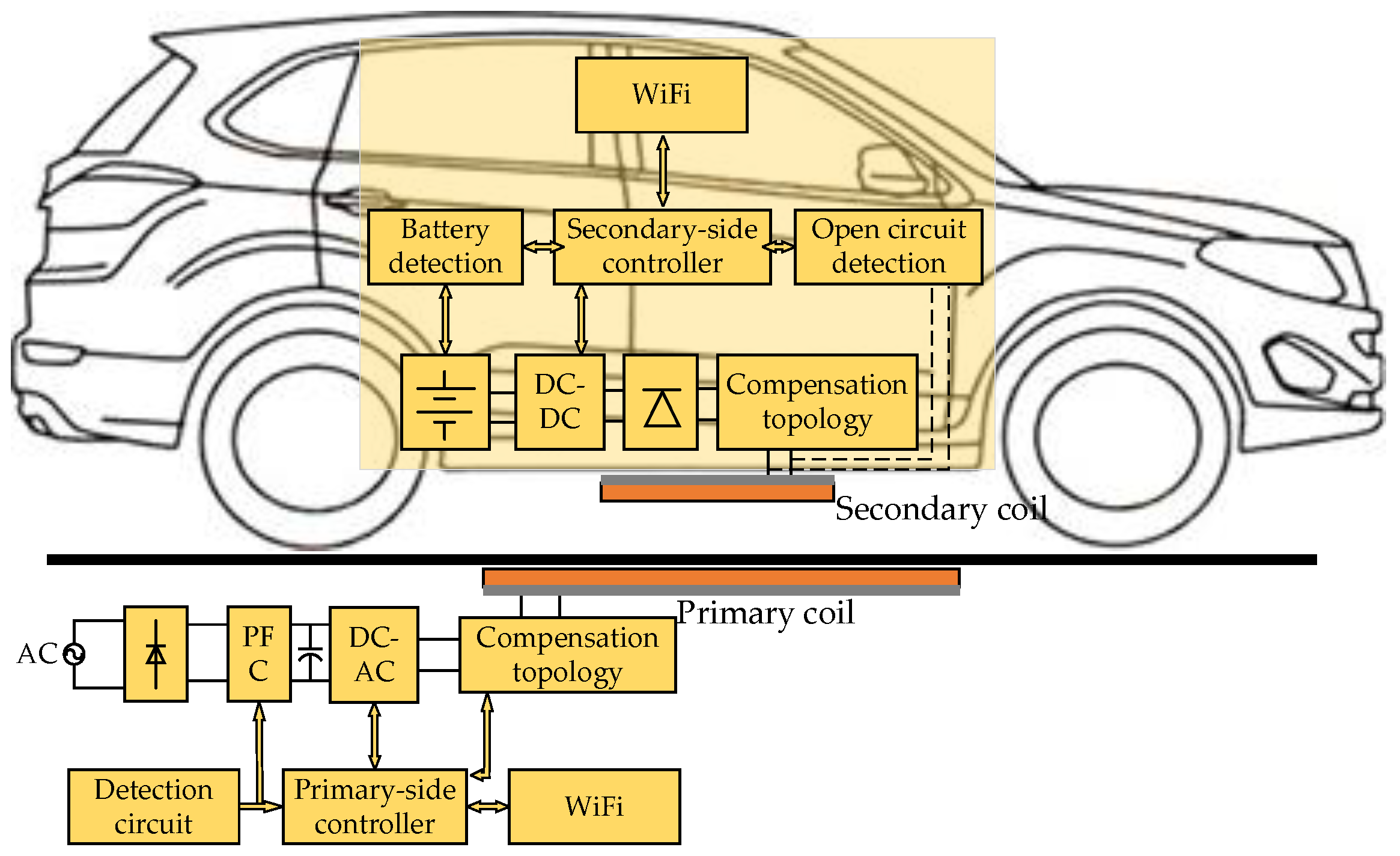
:1. Introduction
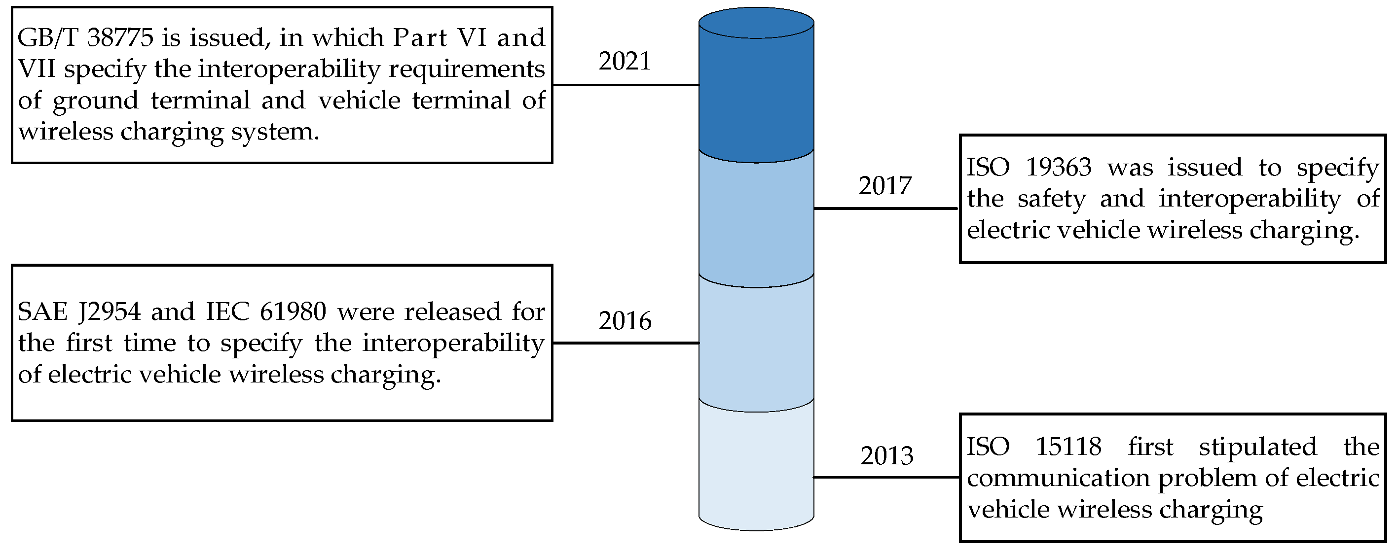
2. Process of Interoperability Standardization
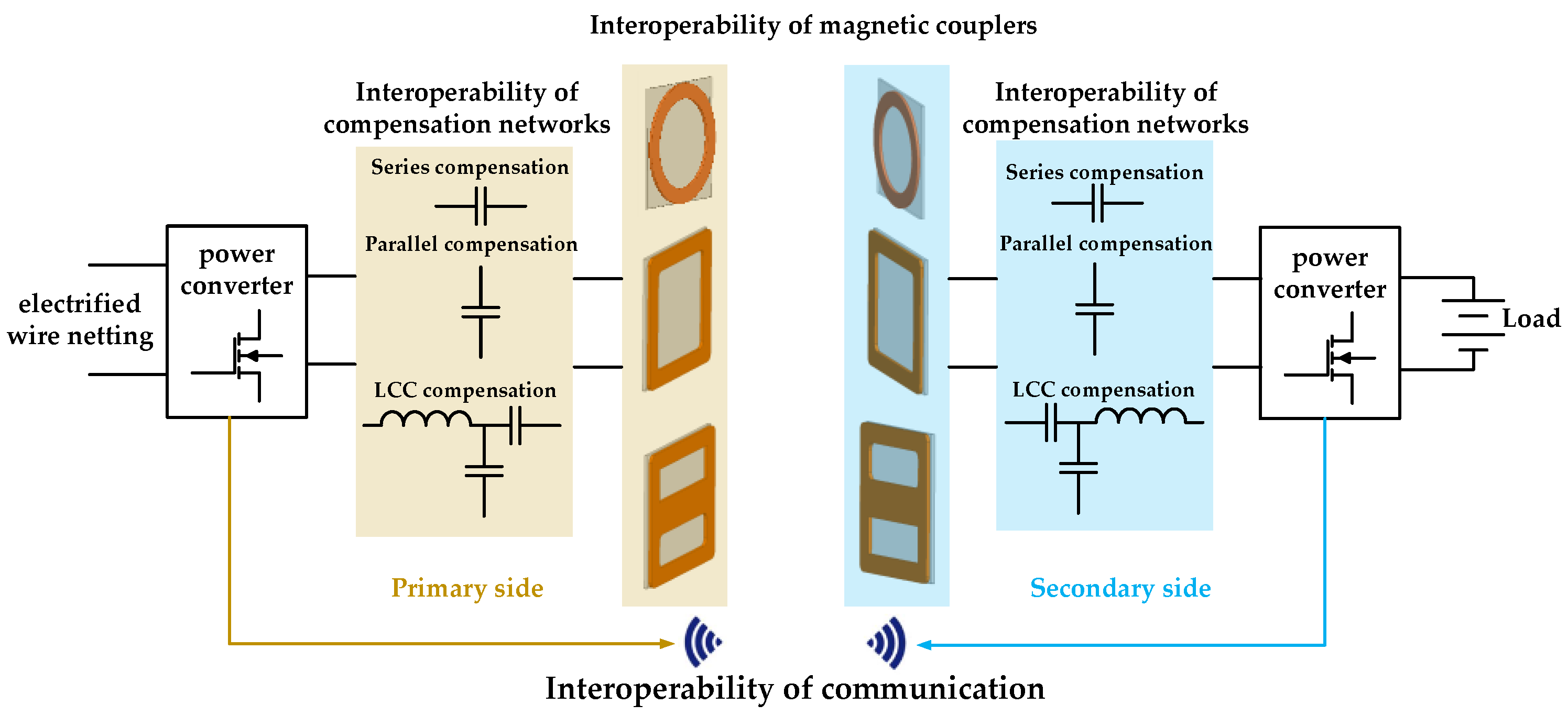
3. Interoperability Analysis and Improvement
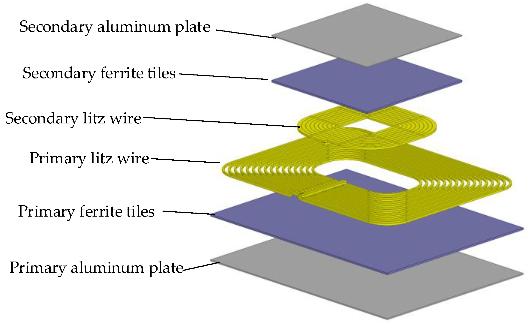
3.1. Interoperability of Different Coils
3.2. Interoperability of Different Topologies
4. Interoperability Evaluation Method
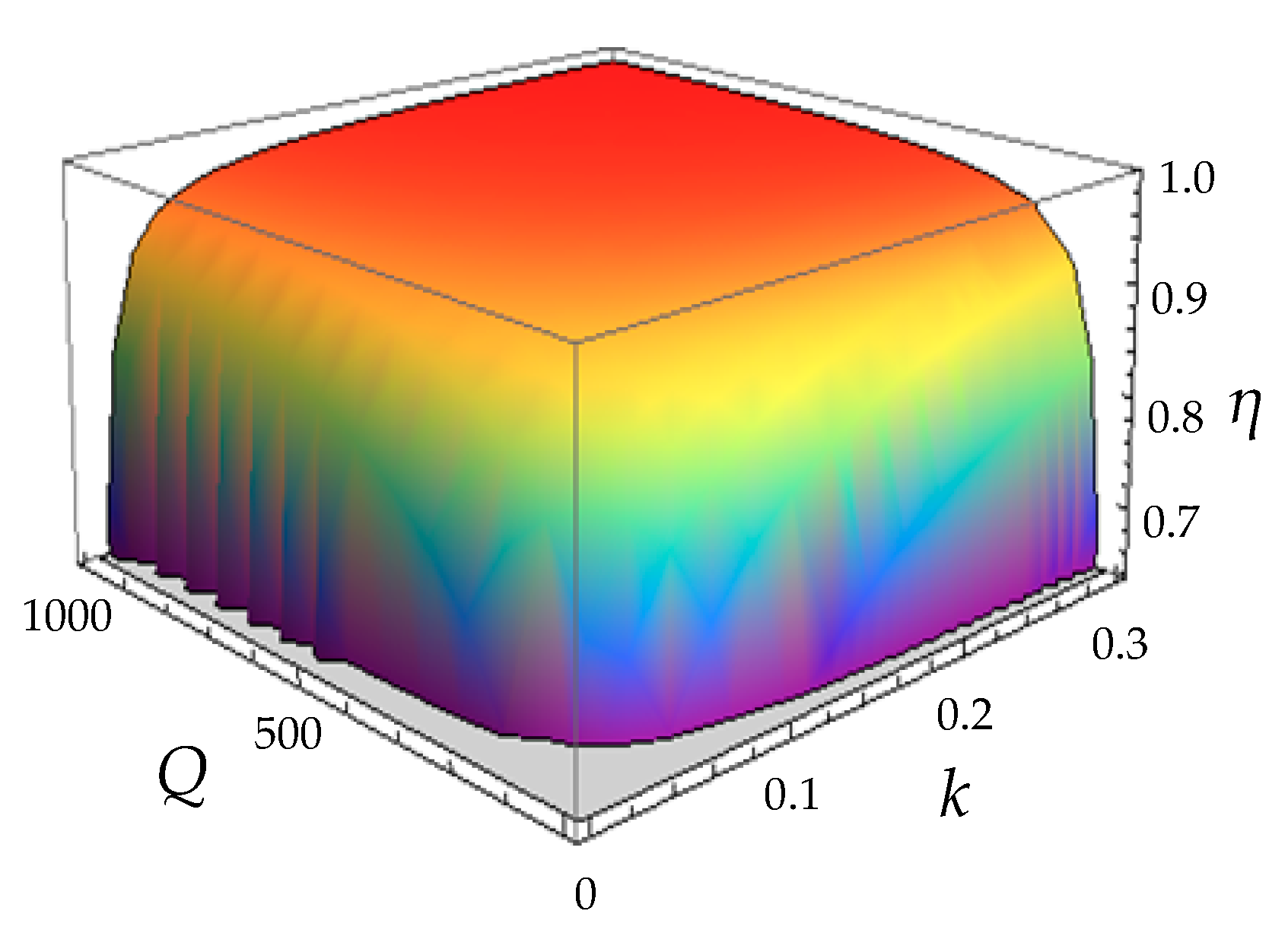
4.1. Evaluation Based on Power Efficiency
4.2. Evaluation Based on Coil Parameters
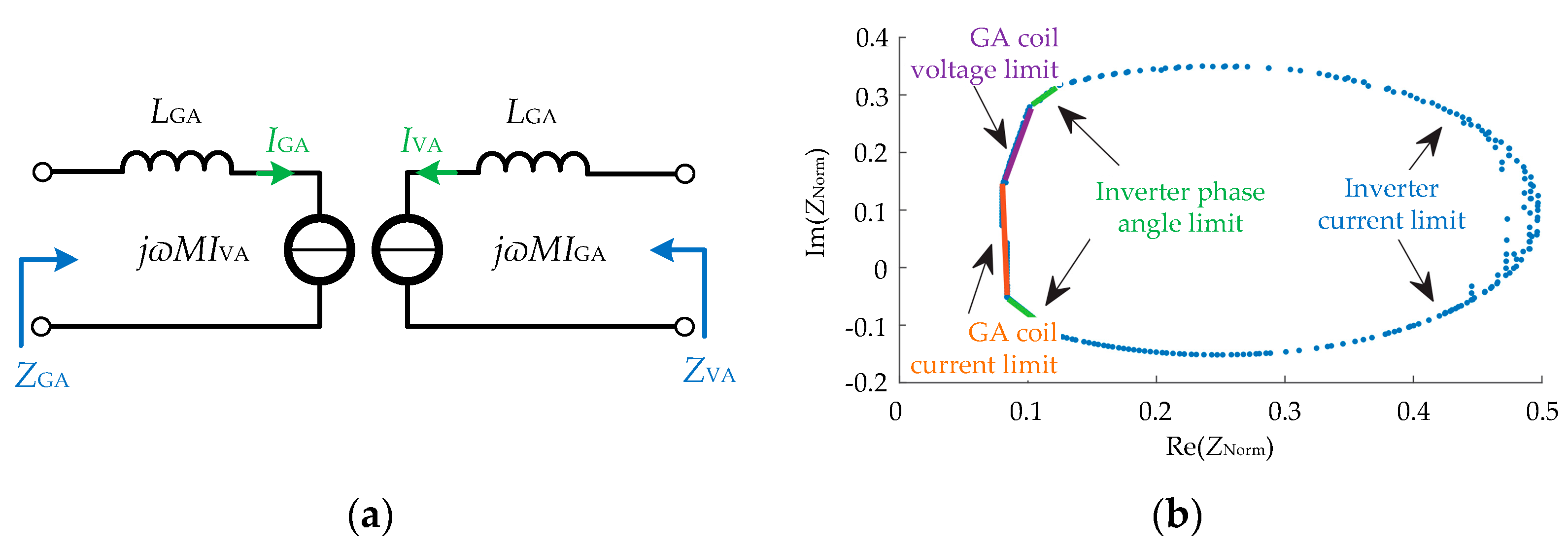
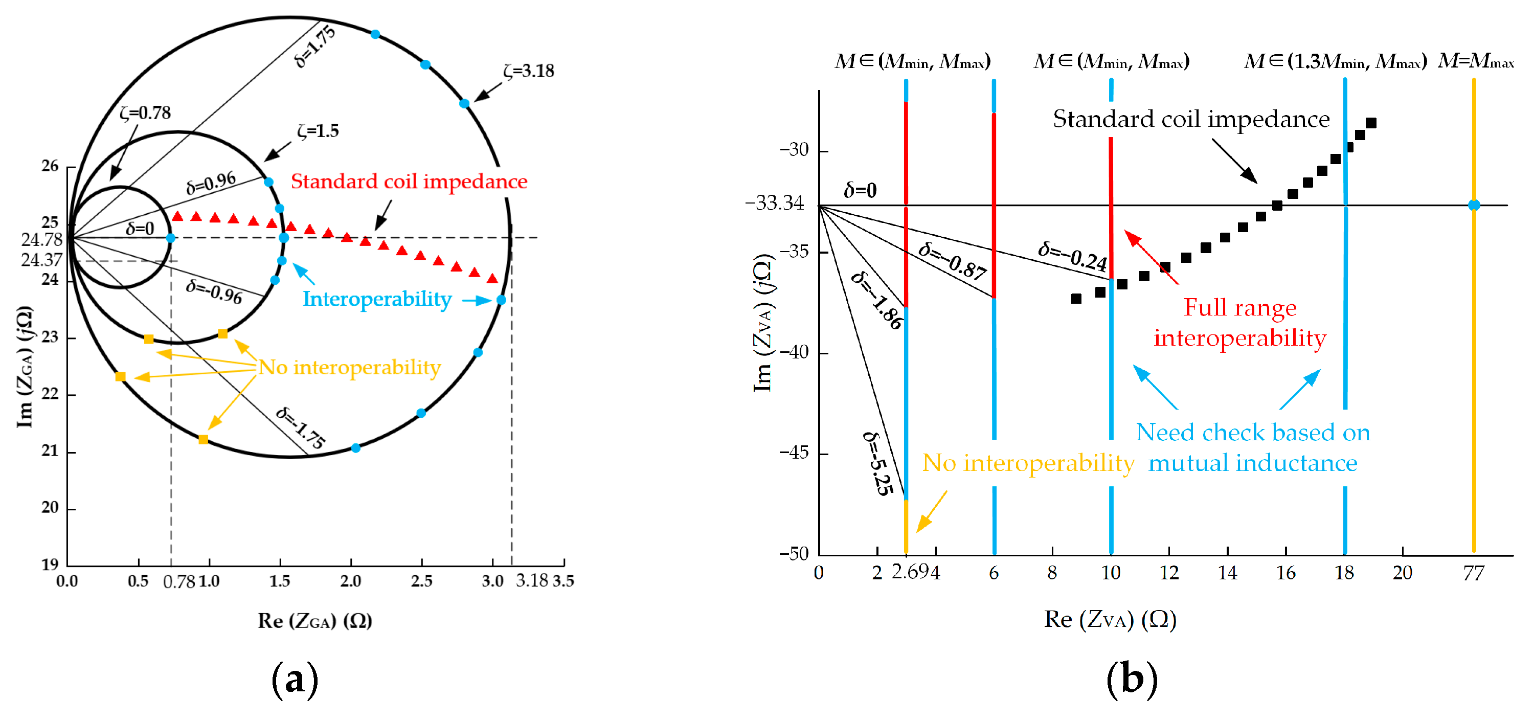
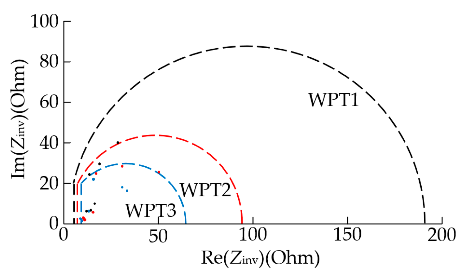
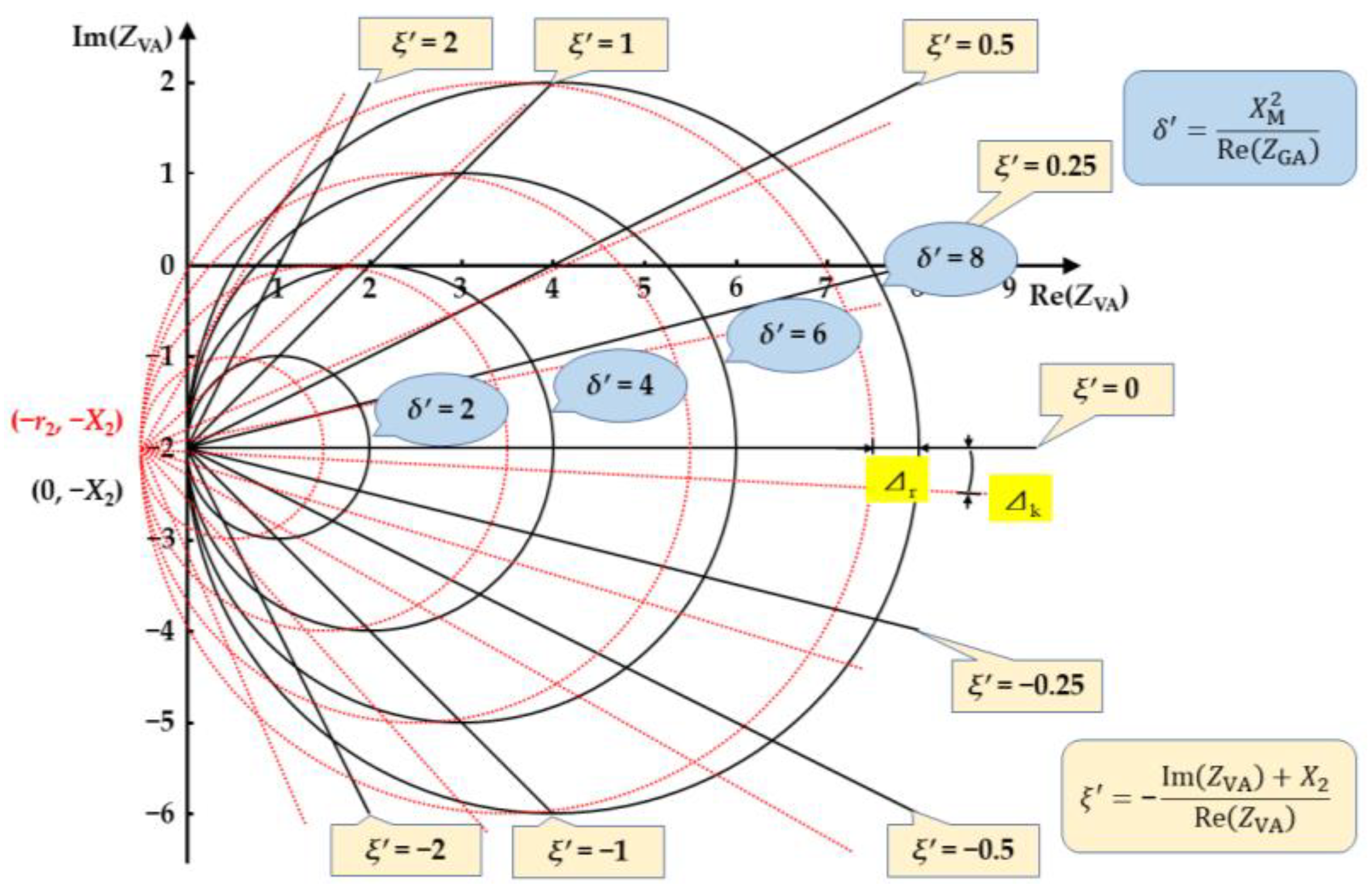
4.3. Evaluation Based on Port Impedance
5. Existing Problems and Expectations
6. Conclusions
Author Contributions
Funding
Data Availability Statement
Conflicts of Interest
References
- Mak, H.Y.; Rong, Y.; Shen, Z.J.M. Infrastructure planning for electric vehicles with battery swapping. Manage. Sci. 2013, 59, 1557–1575. [Google Scholar] [CrossRef]
- Noorollahi, Y.; Golshanfard, A.; Aligholian, A.; Mohammadi-ivatloo, B.; Nielsen, S.; Hajinezhad, A. Sustainable energy system planning for an industrial zone by integrating electric vehicles as energy Storage. J. Energy Storage 2020, 30, 101553. [Google Scholar] [CrossRef]
- Alkawsi, G.; Baashar, Y.; Abbas, D.U.; Alkahtani, A.A.; Tiong, S.K. Review of renewable energy-based charging infrastructure for electric vehicles. Appl. Sci. 2021, 11, 3847. [Google Scholar] [CrossRef]
- Detka, K.; Gorecki, K. Wireless power transfer—A review. Energies 2022, 15, 7236. [Google Scholar] [CrossRef]
- Zhang, Z.; Pang, H.; Georgiadis, A.; Cecati, C. Wireless power transfer-an overview. IEEE Trans. Ind. Electron. 2019, 66, 1044–1058. [Google Scholar] [CrossRef]
- Mahesh, A.; Chokkalingam, B.; Mihet-Popa, L. Inductive wireless power transfer charging for electric vehicles-a review. IEEE Access 2021, 9, 137667–137713. [Google Scholar] [CrossRef]
- Ahmad, A.; Alam, M.S.; Chabaan, R. A comprehensive review of wireless charging technologies for electric vehicles. IEEE Trans. Transport. Electrific. 2018, 4, 38–63. [Google Scholar] [CrossRef]
- Lecluyse, C.; Minnaert, B.; Kleemann, M. A review of the current state of technology of capacitive wireless power transfer. Energies 2021, 14, 5862. [Google Scholar] [CrossRef]
- Wang, Z.; Zhang, Y.; He, X.; Luo, B.; Mai, R. Research and application of capacitive power transfer system: A review. Electronics 2022, 11, 1158. [Google Scholar] [CrossRef]
- Shi, B.; Wen, F.; Chu, X. A multireceiver wireless power supply system with power equalization in stereoscopic space. Electronics 2021, 10, 713. [Google Scholar] [CrossRef]
- Park, Y.-J. Next-generation wireless charging systems for mobile devices. Energies 2022, 15, 3119. [Google Scholar] [CrossRef]
- Park, Y.-J.; Kim, J.-E.; Na, K.-M.; Yang, K.-D.; Cho, K.-H. Optimization and analysis of multilayer planar spiral coils for the application of magnetic resonance wireless power transfer to wearable devices. Energies 2021, 14, 5113. [Google Scholar] [CrossRef]
- Van, S.D.; Ngo, H.Q.; Cotton, S.L. Wireless powered wearables using distributed massive mimo. IEEE Trans. Commun. 2020, 68, 2156–2172. [Google Scholar] [CrossRef]
- Mahmood, M.F.; Mohammed, S.L.; Gharghan, S.K. Ultrasound sensor-based wireless power transfer for low-power medical devices. J. Low Power Electron. Appl. 2019, 9, 20. [Google Scholar] [CrossRef]
- Wang, G.; Liu, W.; Sivaprakasam, M.; Kendir, G.A. Design and analysis of an adaptive transcutaneous power telemetry for biomedical implants. IEEE Trans. Circuits Syst. I Regul. Pap. 2005, 52, 2109–2117. [Google Scholar] [CrossRef]
- Liu, Y.; Zhang, J.; Zhu, C.; Chan, C.C. A study on the safety analysis of an inductive power transfer system for kitchen appliances. Energies 2022, 15, 5218. [Google Scholar] [CrossRef]
- Chow, J.P.-W.; Chung, H.S.-H.; Chan, L.L.-H.; Shen, R.; Tang, S.C. Optimal design and experimental assessment of a wireless power transfer system for home-cage monitoring. IEEE Trans. Power Electron. 2019, 34, 9779–9793. [Google Scholar] [CrossRef]
- Aziz, A.F.A.; Romlie, M.F.; Baharudin, Z. Review of inductively coupled power transfer for electric vehicle charging. IET Power Electron. 2019, 12, 3611–3623. [Google Scholar] [CrossRef]
- Mou, X.; Gladwin, D.T.; Zhao, R.; Sun, H. Survey on magnetic resonant coupling wireless power transfer technology for electric vehicle charging. IET Power Electron. 2019, 12, 3005–3020. [Google Scholar] [CrossRef]
- Trivino, A.; Gonzalez-Gonzalez, J.M.; Aguado, J.A. Wireless power transfer technologies applied to electric vehicles: A review. Energies 2021, 14, 1547. [Google Scholar] [CrossRef]
- Kashani, S.A.; Soleimani, A.; Khosravi, A.; Mirsalim, M. State-of-the-art research on wireless charging of electric vehicles using solar energy. Energies 2023, 16, 282. [Google Scholar] [CrossRef]
- Mohamed, A.A.S.; Shaier, A.A.; Metwally, H.; Selem, S.I. An overview of dynamic inductive charging for electric vehicles. Energies 2022, 15, 5613. [Google Scholar] [CrossRef]
- Palani, G.; Sengamalai, U. A Critical Review on Inductive Wireless Power Transfer Charging System in Electric Vehicle; Wiley: Hoboken, NJ, USA, 2022. [Google Scholar]
- Chittoor, P.K.; Chokkalingam, B.; Mihet-Popa, L. A review on uav wireless charging: Fundamentals, applications, charging techniques and standards. IEEE Access 2021, 9, 69235–69266. [Google Scholar] [CrossRef]
- Wu, M.; Su, L.; Chen, J.; Duan, X.; Wu, D.; Cheng, Y.; Jiang, Y. Development and prospect of wireless power transfer technology used to power unmanned aerial vehicle. Electronics 2022, 11, 2297. [Google Scholar] [CrossRef]
- Wu, S.; Cai, C.; Liu, X.; Chai, W.; Yang, S. Compact and free-positioning omnidirectional wireless power transfer system for unmanned aerial vehicle charging applications. IEEE Trans. Power Electron. 2022, 37, 8790–8794. [Google Scholar] [CrossRef]
- Nguyen, M.T.; Nguyen, C.V.; Truong, L.H.; Le, A.M.; Quyen, T.V.; Masaracchia, A.; Teague, K.A. Electromagnetic field based wpt technologies for uavs: A comprehensive survey. Electronics 2020, 9, 461. [Google Scholar] [CrossRef]
- Teeneti, C.R.; Truscott, T.T.; Beal, D.N.; Pantic, Z. Review of wireless charging systems for autonomous underwater vehicles. IEEE J. Ocean. Eng. 2019, 46, 68–87. [Google Scholar] [CrossRef]
- Wang, D.a.; Cui, S.; Zhang, J.; Bie, Z.; Song, K.; Zhu, C. A Novel Arc-shaped lightweight magnetic coupler for auv wireless power transfer. IEEE Trans. Ind. Appl. 2022, 58, 1315–1329. [Google Scholar] [CrossRef]
- Niu, S.; Zhao, Q.; Chen, H.; Yu, H.; Niu, S.; Jian, L. Underwater wireless charging system of unmanned surface vehicles with high power, large misalignment tolerance and light weight: Analysis, design and optimization. Energies 2022, 15, 9529. [Google Scholar] [CrossRef]
- Kim, J.; Kim, K.; Kim, H.; Kim, D.; Park, J.; Ahn, S. An efficient modeling for underwater wireless power transfer using z-parameters. IEEE Trans. Electromagn. Compat. 2019, 61, 2006–2014. [Google Scholar] [CrossRef]
- Guidi, G.; Suul, J.A.; Jenset, F.; Sorfonn, I. Wireless charging for ships: High-power inductive charging for battery electric and plug-in hybrid vessels. IEEE Electrif. Mag. 2017, 5, 22–32. [Google Scholar] [CrossRef]
- Abdolkhani, A.; Hu, A.P.; Nair, N.-K.C. A double stator through-hole type contactless slipring for rotary wireless power transfer applications. IEEE Trans. Energy Convers. 2014, 29, 426–434. [Google Scholar]
- Ji, B.; Chen, Z.; Mumtaz, S.; Liu, J.; Zhang, Y.; Zhu, J.; Li, C. Swipt enabled intelligent transportation systems with advanced sensing fusion. IEEE Sens. J. 2021, 21, 15643–15650. [Google Scholar] [CrossRef]
- Zhou, Z.; Liu, Z.; Su, H.; Zhang, L. Intelligent path planning strategy for electric vehicles combined with urban electrified transportation network and power grid. IEEE Syst. J. 2022, 16, 2437–2447. [Google Scholar] [CrossRef]
- Zhang, S.; Yu, J.J.Q. Electric vehicle dynamic wireless charging system: Optimal placement and vehicle-to-grid scheduling. IEEE Internet Things J. 2022, 9, 6047–6057. [Google Scholar] [CrossRef]
- Onar, O.C.; Chinthavali, M.; Campbell, S.L.; Seiber, L.E.; White, C.P. Vehicular integration of wireless power transfer systems and hardware interoperability case studies. IEEE Trans. Ind. Appl. 2019, 55, 5223–5234. [Google Scholar] [CrossRef]
- Miller, J.M.; Onar, O.C.; Chinthavali, M. Primary-side power flow control of wireless power transfer for electric vehicle charging. IEEE J. Emerg. Sel. Topics Ind. Electron. 2015, 3, 147–162. [Google Scholar] [CrossRef]
- Okasili, I.; Elkhateb, A.; Littler, T. A review of wireless power transfer systems for electric vehicle battery charging with a focus on inductive coupling. Electronics 2022, 11, 1355. [Google Scholar] [CrossRef]
- Venkatesan, M.; Rajamanickam, N.; Vishnuram, P.; Bajaj, M.; Blazek, V.; Prokop, L.; Misak, S. A review of compensation topologies and control techniques of bidirectional wireless power transfer systems for electric vehicle applications. Energies 2022, 15, 7816. [Google Scholar] [CrossRef]
- Ombach, G.; Kurschner, D.; Mathar, S. Universal base coil solution for interoperable system for stationary wireless ev charging. In Proceedings of the 2015 International Conference on Sustainable Mobility Applications, Renewables and Technology (SMART), Kuwait, Kuwait, 23–25 November 2015. [Google Scholar]
- Ibrahim, M.; Bernard, L.; Pichon, L.; Laboure, E.; Razek, A.; Cayol, O.; Ladas, D.; Irving, J. Inductive charger for electric vehicle: Advanced modeling and interoperability analysis. IEEE Trans. Power Electron. 2016, 31, 8096–8114. [Google Scholar] [CrossRef]
- Simon, O.; Krempel, T.; Schnurbusch, W.; Hoppe, A.; Turki, F. Proposal of a power source definition to provide interoperable use of wireless power transfer systems. In Proceedings of the 2014 IEEE International Electric Vehicle Conference (IEVC 2014), Florence, Italy, 17–19 December 2014. [Google Scholar]
- Vaidya, B.; Mouftah, H.T. Deployment of secure ev charging system using open charge point protocol. In Proceedings of the 14th International Wireless Communications and Mobile Computing Conference (IWCMC 2018), Limassol, Cyprus, 25–29 June 2018. [Google Scholar]
- Ancillotti, E.; Bruno, R.; Palumbo, S.; Capasso, C.; Veneri, O. Experimental set-up of dc pev charging station supported by open and interoperable communication technologies. In Proceedings of the 2016 International Symposium on Power Electronics, Electrical Drives, Automation and Motion (SPEEDAM 2016), Capri, Italy, 22–24 June 2016. [Google Scholar]
- Karpenko, A.; Kinnunen, T.; Madhikermi, M.; Robert, J.; Framling, K.; Dave, B.; Nurminen, A. Data exchange interoperability in iot ecosystem for smart parking and ev charging. Sensors 2018, 18, 4404. [Google Scholar] [CrossRef] [Green Version]
- ISO 15118-1; Road Vehicles—Vehicle to Grid Communication Interface—part 1: General Information and Use-Case Definition. KTH Royal Institute of Technology: Stockholm, Sweden, 2013.
- SAE J2954; Wireless Power Transfer for Light-Duty Plug-in/Electric Vehicles and Alignment Methodology. SAE International: Pittsburgh, PA, USA, 2016.
- IEC 61980; Electric Vehicle Wireless Power Transfer (wpt) Systems—Part 1: General Requirements. International Electrotechnical Commission: Geneva, Switzerland, 2016.
- ISO 19163; Electrically Propelled Road Vehicles—Magnetic Field Wireless Power Transfer—Safety and Interoperability Requirements. ISO: Geneva, Switzerland, 2017.
- GB/T 38775.6; Electric Vehicle Wireless Power Transfer—Part 6: Interoperability Requirements and Testing—Ground Side, China. Standards Press of China: Beijing, China, 2021.
- GB/T 38775.7; Electric Vehicle Wireless Power Transfer—Part 7:Interoperability Requirements and Testing—Vehicle Side, China. Standards Press of China: Beijing, China, 2021.
- T/CPSS 1001-2022; Technical specification for high-power wireless charging of electric vehicles, China. Standards Press of China: Beijing, China, 2022.
- Kishan, D.; Vinod, M.; Harischandrappa, N. Magnetic coupling characteristics of spiral square—Circular coupled coils for wireless ev battery charging system. In Proceedings of the 2020 IEEE 17th India Council International Conference (INDICON), New Delhi, India, 10–13 December 2020. [Google Scholar]
- Al-Saadi, M.; Valtchev, S.; Romba, L.; Goncalves, J.; Crciunescu, A. comparison of spiral and square coil configurations in wireless power transfer system for contactless battery charging. In Proceedings of the 2019 Electric Vehicles International Conference (EV 2019), Bucharest, Romania, 3–4 October 2019. [Google Scholar]
- Zhang, W.; White, J.C.; Abraham, A.M.; Mi, C.C. Loosely coupled transformer structure and interoperability study for ev wireless charging systems. IEEE Trans. Power Electron. 2015, 30, 6356–6367. [Google Scholar] [CrossRef]
- Lammle, T.; Parspour, N.; Holz, J. Comparison of circular and double-d coil topologies for automotive inductive charging systems. In Proceedings of the 2020 IEEE PELS Workshop on Emerging Technologies: Wireless Power Transfer (WoW), Seoul, Republic of Korea, 15–19 November 2020. [Google Scholar]
- Mohammad, M.; Onar, O.C.; Pries, J.L.; Galigekere, V.P.; Su, G.-J.; Wilkins, J. Analysis of magnetic field emissions and shield requirements for interoperating high-power ev wireless charging system. In Proceedings of the 36th Annual IEEE Applied Power Electronics Conference and Exposition (APEC 2021), Virtual, Online, USA, 14–17 June 2021. [Google Scholar]
- Yang, G.; Song, K.; We, R.; Huang, X.; Zhang, H.; Zhang, Q.; Zhu, C. Interoperability improvement for wireless electric vehicle charging system using adaptive phase-control transmitter. IEEE Access 2019, 7, 41365–41379. [Google Scholar] [CrossRef]
- Yang, G.; Song, K.; Sun, Y.; Huang, X.; Li, J.; Guo, Y.; Zhang, H.; Zhang, Q.; Lu, R.; Zhu, C. Interoperability improvement for rectangular pad and dd pad of wireless electric vehicle charging system based on adaptive position adjustment. IEEE Trans. on Ind. Appl. 2021, 57, 2613–2624. [Google Scholar] [CrossRef]
- Budhia, M.; Boys, J.T.; Covic, G.A.; Huang, C.-Y. Development of a single-sided flux magnetic coupler for electric vehicle ipt charging systems. IEEE Trans. Ind. Electron. 2013, 60, 318–328. [Google Scholar] [CrossRef]
- Lei, Z.; Ruddell, S.; Thrimawithana, D.J.; Madawala, U.K.; Hu, P.A. A hybrid wireless charging system with ddq pads for dynamic charging of evs. In Proceedings of the 2017 IEEE PELS Workshop on Emerging Technologies: Wireless Power Transfer (WoW), Chongqing, China, 20–22 May 2017. [Google Scholar]
- Alam, M.M.; Mekhilef, S.; Seyedmahmoudian, M.; Horan, B. Dynamic charging of electric vehicle with negligible power transfer fluctuation. Energies 2017, 10, 701. [Google Scholar] [CrossRef]
- Ahmad, A.; Alam, M.S.; Mohamed, A.A.S. Design and interoperability analysis of quadruple pad structure for electric vehicle wireless charging application. IEEE Trans. Transport. Electrific. 2019, 5, 934–945. [Google Scholar] [CrossRef]
- Liu, Y.; Mai, R.; Liu, D.; Li, Y.; He, Z. Efficiency optimization for wireless dynamic charging system with overlapped dd coil arrays. IEEE Trans. Power Electron. 2018, 33, 2832–2846. [Google Scholar] [CrossRef]
- Kim, S.; Zaheer, A.; Covic, G.; Boys, J. Tripolar pad for inductive power transfer systems. In Proceedings of the IECON 2014—40th Annual Conference of the IEEE Industrial Electronics Society, Dallas, TX, USA, 29 October 2014–1 November 2014. [Google Scholar]
- Kim, S.; Covic, G.A.; Boys, J.T. Tripolar pad for inductive power transfer systems for ev charging. IEEE Trans. Power Electron. 2017, 32, 5045–5057. [Google Scholar] [CrossRef]
- Liao, Z.-J.; Feng, Q.-K.; Jiang, C.-H.; Wu, F.; Xia, C.-Y.; Yu, D.-S. Analysis and design of eit-like magnetic coupling wireless power transfer systems. IEEE Trans. Circuits Syst. 2021, 68, 3103–3113. [Google Scholar] [CrossRef]
- Kurpat, T.; Eckstein, L. A three-phase inductive power transfer coil with sae j2954 wpt3 magnetic interoperability. In Proceedings of the 2019 IEEE PELS Workshop on Emerging Technologies: Wireless Power Transfer (WoW 2019), London, UK, 17–21 June 2019. [Google Scholar]
- Sun, K.; Covic, G.A.; Thrimawithana, D.; Kim, S. Reduced switch operation of the tripolar for interoperability in inductive power transfer. In Proceedings of the IEEE MTT-S Wireless Power Transfer Conference (WPTC)/IEEE PELS Workshop on Emerging Technologies—Wireless Power (WoW)/Wireless Power Week Conference, London, UK, 18–21 June 2019. [Google Scholar]
- Hou, J.; Chen, Q.; Zhang, Z.; Wong, S.-C.; Tse, C.K. Analysis of output current characteristics for higher order primary compensation in inductive power transfer systems. IEEE Trans. Power Electron. 2018, 33, 6807–6821. [Google Scholar] [CrossRef]
- Mude, K.N.; Aditya, K. Comprehensive review and analysis of two-element resonant compensation topologies for wireless inductive power transfer systems. Chin. J. Electr. Eng. 2019, 5, 14–31. [Google Scholar] [CrossRef]
- Li, S.; Li, W.; Deng, J.; Trong Duy, N.; Mi, C.C. A double-sided lcc compensation network and its tuning method for wireless power transfer. IEEE Trans. Veh. Technol. 2015, 64, 2261–2273. [Google Scholar] [CrossRef]
- Li, W.; Zhao, H.; Deng, J.; Li, S.; Mi, C.C. Comparison study on ss and double-sided lcc compensation topologies for ev/phev wireless chargers. IEEE Trans. Veh. Technol. 2016, 65, 4429–4439. [Google Scholar] [CrossRef]
- Li, W.; Han, Z.; Kan, T.; Mi, C. Inter-operability considerations of the double-sided lcc compensated wireless charger for electric vehicle and plug-in hybrid electric vehicle applications. In Proceedings of the 2015 IEEE PELS Workshop on Emerging Technologies: Wireless Power (2015 WoW), Daejeon, Republic of Korea, 5–6 June 2015. [Google Scholar]
- Guo, Y.; Zhang, Y.; Yan, B.; Wang, K.; Zhang, Z.; Wang, L. Interoperability analysis of compensation network in electric vehicle wireless charging system. In Proceedings of the 2018 IEEE International Power Electronics and Application Conference and Exposition (PEAC), Shenzhen, China, 4–7 November 2018. [Google Scholar]
- Ombach, G.; Kurschner, D.; Mathar, S.; Chlebosz, W. Optimum magnetic solution for interoperable system for stationary wireless ev charging. In Proceedings of the 2015 Tenth International Conference on Ecological Vehicles and Renewable Energies (EVER), Monte Carlo, Monaco, 31 March 2015–2 April 2015. [Google Scholar]
- Simon, O.; Mahlein, J.; Turki, F.; Dörflinger, D.; Hoppe, A. Field test results of interoperable electric vehicle wireless power transfer. In Proceedings of the European Conference on Power Electronics & Applications, Karlsruhe, Germany, 5–9 September 2016. [Google Scholar]
- Ombach, G. Design and safety considerations of interoperable wireless charging system for automotive. In Proceedings of the 2014 Ninth International Conference on Ecological Vehicles and Renewable Energies (EVER), Monte-Carlo, Monaco, 25–27 March 2014. [Google Scholar]
- Schneider, J.; Carlson, R.; Sirota, J.; Sutton, R.; Taha, E.; Kesler, M.; Kamichi, K.; Teerlinck, I.; Abeta, H.; Minagawa, Y.; et al. Validation of wireless power transfer up to 11kw based on sae j2954 with bench and vehicle testing. In Proceedings of the SAE World Congress Experience (WCX 2019), Detroit, MI, USA, 9–11 April 2019. [Google Scholar]
- Miller, J.M.; Schrafel, P.C.; Long, B.R.; Daga, A. The wpt dilemma-high k or high q? In Proceedings of the 2016 IEEE PELS Workshop on Emerging Technologies: Wireless Power (WoW 2016), Knoxville, TN, USA, 4–6 October 2016. [Google Scholar]
- Kalra, G.R.; Pearce, M.G.S.; Kim, S.; Thrimawithana, D.J.; Covic, G.A. Measuring the q-factor of ipt magnetic couplers. In Proceedings of the 2019 IEEE PELS Workshop on Emerging Technologies: Wireless Power Transfer (WoW 2019), London, UK, 17–21 June 2019. [Google Scholar]
- Barth, D.; Cortese, G.; Darrat, A.H.; Cheng, C.; Wohr, E.; Suriyah, M.R.; Leibfried, T. Interoperability rating of wireless charging equipment using a decoupled impedance interface. In Proceedings of the 17th IEEE Vehicle Power and Propulsion Conference (VPPC 2020), Virtual, Gijon, Spain, 18 November–16 December 2020. [Google Scholar]
- Hassler, M.; Niedermeier, F.; Krammer, J.; Diepold, K. A Method for interoperable interface description of inductive power transfer systems. In Proceedings of the 2018 IEEE PELS Workshop on Emerging Technologies: Wireless Power Transfer (Wow 2018), Montreal, QC, Canada, 3–7 July 2018. [Google Scholar]
- Kraus, D.; Hassler, M.; Covic, G.; Herzog, H.-G. Impedance based design method for interoperable wireless power transfer systems. In Proceedings of the 13th IEEE Energy Conversion Congress and Exposition (ECCE 2021), Virtual, Online, Canada, 10–14 October 2021. [Google Scholar]
- Song, K.; Yang, G.; Wei, R.; Huang, X.; Zhang, Q.; Zhu, C. Interoperability evaluation of wireless electric vehicle charging systems based on impedance. In Proceedings of the 11th Annual IEEE Energy Conversion Congress and Exposition (ECCE 2019), Baltimore, MD, USA, 29 September–3 October 2019. [Google Scholar]
- Shi, B.; Yang, F.; Wei, B.; Ouyang, M. Electrical interoperability evaluating of wireless ev charging systems based on impedance space. World Electr. Veh. J. 2021, 12, 245. [Google Scholar] [CrossRef]
- Zhang, X.; Chen, Z.; Sha, L.; Yang, Q.; Li, Y.; Han, D. Research on interoperability evaluation method of electric vehicle wireless power transfer system based on three parameters characterization. Proc. CSEE China 2022, 42, 1569–1582. [Google Scholar]
- Zhang, X.; Bai, X.; Sha, L.; Chen, Z.; Yang, Q. Research on interoperability evaluation method of different coils in wireless charging system of electric vehicles. Trans. China Electrotech. Soc. China 2020, 35, 4150–4160. [Google Scholar]
- Sha, L.; Liu, J.; Chen, Z. Research on evaluation method of electric vehicle wireless charging interoperability based on two parameter representation. Processes 2022, 10, 1591. [Google Scholar] [CrossRef]
- Yang, G.; Song, K.; Huang, X.; Wang, C.; Huang, X.; Li, J.; Zhu, C. Improved interoperability evaluation method for wireless charging systems based on interface impedance. IEEE Trans. Power Electron. 2021, 36, 8588–8592. [Google Scholar] [CrossRef]
- Hassler, M.; Atasoy, O.; Kesler, M.; Twelker, K.; Achatz, T.; Jetz, M.; Krammer, J. Impedance measurement on inductive power transfer systems. In Proceedings of the 2019 IEEE PELS Workshop on Emerging Technologies: Wireless Power Transfer (WoW 2019), London, UK, 17–21 June 2019. [Google Scholar]
- Kraus, D.; Damhuis, C.; Covic, G.; Herzog, H.-G. Leakage field and compensation assessment of an interoperable high power 50 kw wireless power transfer system using an impedance plane method. In Proceedings of the Wireless Power Week (WPW), Bordeaux, France, 5–8 July 2022. [Google Scholar]
- Kraus, D.; Vangapandu, S.V.; Herzog, H.G. Interoperability analysis of two different coil systems for inductive power transfer. In Proceedings of the 21st European Conference on Power Electronics and Applications (EPE ECCE Europe), Genova, Italy, 3–5 September 2019. [Google Scholar]
- Arfeen, Z.A.; Abdullah, M.P.; Hassan, R.; Othman, B.M.; Siddique, A.; Rehman, A.U.; Sheikh, U.U. Energy storage usages: Engineering reactions, economic-technological values for electric vehicles-a technological outlook. Int. Trans. Electr. Energy Syst. 2020, 30, e12422. [Google Scholar] [CrossRef]
- Emodi, N.V.; Dwyer, S.; Nagrath, K.; Alabi, J. Electromobility in australia: Tariff design Structure and consumer preferences for mobile distributed energy storage. Sustainability 2022, 14, 6631. [Google Scholar] [CrossRef]
- Sharma, A.; Sharma, S. Review of power electronics in vehicle-to-grid systems. J. Energy Storage 2019, 21, 337–361. [Google Scholar] [CrossRef]
- Joseph, P.K.; Devaraj, E.; Gopal, A. Overview of wireless charging and vehicle-to-grid integration of electric vehicles using renewable energy for sustainable transportation. IET Power Electron. 2019, 12, 627–638. [Google Scholar] [CrossRef]
- Ouramdane, O.; Elbouchikhi, E.; Amirat, Y.; Gooya, E.S. Optimal sizing and energy management of microgrids with vehicle-to-grid technology: A critical review and future trends. Energies 2021, 14, 4166. [Google Scholar] [CrossRef]
- Hussain, M.T.; Bin Sulaiman, N.; Hussain, M.S.; Jabir, M. Optimal management strategies to solve issues of grid having electric vehicles (ev): A review. J. Energy Storage 2021, 33, 102114. [Google Scholar] [CrossRef]
- Inci, M.; Savrun, M.M.; Celik, O. Integrating electric vehicles as virtual power plants: A comprehensive review on vehicle-to-grid (v2g) concepts, interface topologies, marketing and future prospects. J. Energy Storage 2022, 55, 105579. [Google Scholar] [CrossRef]
- Alsharif, A.; Tan, C.W.; Ayop, R.; Dobi, A.; Lau, K.Y. A comprehensive review of energy management strategy in vehicle-to-grid technology integrated with renewable energy sources. Sustain. Energy Technol. Assess. 2021, 47, 101439. [Google Scholar] [CrossRef]
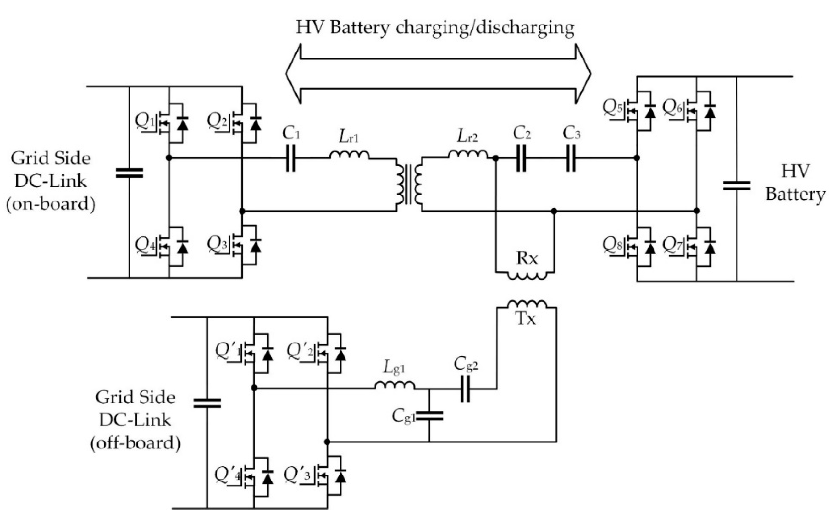
- Elshaer, M.; Bell, C.; Hamid, A.; Wang, J. DC-DC topology for interfacing a wireless power transfer system to an on-board conductive charger for plug-in electric vehicles. IEEE Trans. Ind. Appl. 2021, 57, 5552–5561. [Google Scholar] [CrossRef]


| VA | ||||
|---|---|---|---|---|
| WPT1 | WPT2 | WPT3 | ||
| GA 1 | WPT1 | Required | Required | Required |
| WPT2 | Required | Required | Required | |
| WPT3 | Required | Required | Required | |
| VA | ||||
|---|---|---|---|---|
| Z1 | Z2 | Z3 | ||
| GA | Z1 | Required | N/A 1 | N/A |
| Z2 | Required | Required | N/A | |
| Z3 | Required | Required | Required | |
| Coil Combination | Equivalent Model | Coupling | Coupling Zero Position | Interoperable Charging Range |
|---|---|---|---|---|
| Circular–Circular |  | Medium | 40% of coil diameter | Less than 40% of coil diameter |
| Rectangular–Circular |  | Medium | 50% of coil length and width | Less than 50% of length and width |
| DD–DD |  | High | About 34% of coil length About 70% of coil width | Less than 34% length, 70% of width |
| Circular–DD |  | High | opposite | Offset about 1/4 coil diameter |
| DD–Circular |  | Low | opposite | Offset about 1/4 coil diameter |
| DD–DDQP |  | High | 77% of coil length and width | Less than 77% of length and width |
| BPP–DD |  | High | 77% of coil length and width | Less than 77% of length and width |
| Topology Combination | Equivalent Model | Rated Power | Load Independence | Frequency Stability | Misalignment Tolerance |
|---|---|---|---|---|---|
| S–S |  | Accessible | Yes | Yes | Poor |
| S–P | 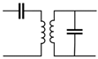 | Accessible | None | None | Poor |
| P–S | 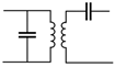 | Inaccessible | None | None | Good |
| P–P | 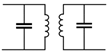 | Inaccessible | None | None | Good |
| LCC–S | 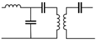 | Accessible | Yes | Yes | Good |
| LCC–P |  | Accessible | Yes | None | Good |
| S–LCC | 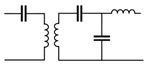 | Accessible | Yes | Yes | Poor |
| P–LCC |  | Accessible under specific coupling | None | None | Poor |
| LCC–LCC | 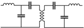 | Accessible | Yes | Yes | Good |
Disclaimer/Publisher’s Note: The statements, opinions and data contained in all publications are solely those of the individual author(s) and contributor(s) and not of MDPI and/or the editor(s). MDPI and/or the editor(s) disclaim responsibility for any injury to people or property resulting from any ideas, methods, instructions or products referred to in the content. |
© 2023 by the authors. Licensee MDPI, Basel, Switzerland. This article is an open access article distributed under the terms and conditions of the Creative Commons Attribution (CC BY) license (https://creativecommons.org/licenses/by/4.0/).
Share and Cite
Song, K.; Lan, Y.; Zhang, X.; Jiang, J.; Sun, C.; Yang, G.; Yang, F.; Lan, H. A Review on Interoperability of Wireless Charging Systems for Electric Vehicles. Energies 2023, 16, 1653. https://doi.org/10.3390/en16041653
Song K, Lan Y, Zhang X, Jiang J, Sun C, Yang G, Yang F, Lan H. A Review on Interoperability of Wireless Charging Systems for Electric Vehicles. Energies. 2023; 16(4):1653. https://doi.org/10.3390/en16041653
Chicago/Turabian StyleSong, Kai, Yu Lan, Xian Zhang, Jinhai Jiang, Chuanyu Sun, Guang Yang, Fengshuo Yang, and Hao Lan. 2023. "A Review on Interoperability of Wireless Charging Systems for Electric Vehicles" Energies 16, no. 4: 1653. https://doi.org/10.3390/en16041653