Abstract
An investigation on a flywheel is presented based on finite element modelling simulations for different geometries. The goal was to optimise the energy density (rotational energy-to-mass ratio) and, at the same time, the rotational energy of a flywheel rotor. The stress behaviour of flywheel rotors under the rotational speed at the maximum stress achievable by the flywheel was analysed. Under this condition, the energy density was obtained for the different geometries, as well as the rotational energy. The best energy density performance due to geometry was achieved with a flywheel rotor presenting a new Gaussian section, which is different from the known Laval disk shape. The best results using a single disk involved a rotational speed of nearly 279,000 rpm and a rotational energy density around 1584 kJ/kg (440 Wh/kg). These values still yielded low total energy; to increase its value, two or three rotors were added to the flywheel, which were analysed in regard to stability. In particular, the triple rotor energy density was ≈ 1550 kJ/kg (431 Wh/kg). As some instability was found in these rotors, a solution using reinforcement was developed to avoid such instabilities. The energy density of such a reinforced double rotor neared 1451 kJ/kg (403 Wh/kg), and the system achieved higher total energy. The material assumed for the devices was carbon fibre Hexcel UHM 12,000, a material kept constant throughout the simulations to allow comparison among the different geometries.
1. Introduction
Energy storage technologies are based on storing electrical, chemical, and mechanical energy for later use as electricity [1]. Among them, flywheels are electromechanical storage systems based on their rotor rotational kinetic energy. They are characterized by fast charging and discharging, high energy density, no environmental pollution, a large range of operating temperatures, and almost unlimited charging and discharging cycles [1,2]. A flywheel electromechanical system includes several components in addition to the rotor or disk such as a motor/generator, power electronic converter, controller, and connection to the power grid [3]. The successive inclusion of these components characterizes what is today called flywheel energy storage systems (FESS). The first generation of flywheel battery systems added circuit rectifiers and frequency inverters, the second generation included AC generators, and the third generation finally included connection to the power grid configuring the currently known FESS [4,5]. Hence, when there is an excess of electrical energy in the electrical grid, FESS stores it by accelerating the rotor using an electrical machine operating as a motor. When there is a demand for energy on the electrical grid, the electrical machine operates as a generator, slows down the rotor, and supplies electrical energy to the grid [4,5,6]. In this work, we focused on increasing the storage capacity of flywheel rotors.
The diversity of components allows FESS to evolve through improvements in their components and also in the way they are arranged in the system or their architecture. Component improvements include magnetic bearings, better electronics, improved vacuum systems, and different classes of motors and generators in addition to improving the energy storage capacity of rotors utilizing stronger materials and different rotor designs [5,6,7,8,9,10,11]. Improvements in terms of architecture generally include design tradeoffs among components [12] aiming at greater safety, the increase in energy storage capacity, the expansion of the range of applications, and the reduction in costs [13,14,15].
In general terms, the applications for FESS include providing several quality services such as regulating energy supply and demand, stability, energy quality, power smoothing, frequency regulation, warrant uninterrupted power supply, and more flexible AC transmission systems (FACTS). They are often used to store short-term energy in grid applications [6]. A plurality of flywheels allows for high power and energy storage to meet a variety of applications [12]. Due to being able to provide such varied quality services for electrical grids, flywheels are incorporated into many stationary and mobile terrestrial, marine, and space applications and are integrated into different renewable energy sources aiming at taking advantage of several of the quality services mentioned in this paragraph [16,17].
Whether they are the the application requirement for a stand-alone FESS or an array of a plurality of FESS, the characteristics of the application environment impose requirements on the FESS such as storage capacity, available free space to accommodate the flywheel system, and weight. The dominant indicators for the various solutions are high energy density (kJ/kg) and total stored energy (kJ) [18,19,20,21]. Rupp et al. [18] studied the use of flywheels in light rail transit. The energy savings were substantial. For high energy densities (10.4 kJ), gains of 31% were obtained, while for low energy densities (4.3 kJ), gains reached 11%.
Sun et al. [19] studied electric vehicles, hybrid energy systems with lithium batteries, and electromechanical flywheels. Energy recovery is greater in urban areas due to constant braking occurring in traffic and lower on highways. An alternative for modern cities is the use of hybrid electric cars with regenerative braking and hybrid systems with flywheels with higher energy storage capacity [20].
Cronk et al. [21] studied a dual pneumatic and electromechanical system for storing more energy. The system included a rotating piston, which stored kinetic and pneumatic energy. Okou et al. [17] used flywheel and lead acid batteries for rural solar energy applications, and there was a cost saving of 37% per kWh for rural applications. Some recent work has focused on the indicator of high energy density [22]. Kale et al. [6] proposed a geometry of disks with circular sections to reduce tensile stress in the material and increase rotation speed and, consequently, energy density. Okou et al. [17] used flywheel rotors with different rotor shapes such as Borat, Berger, and Stodola [22], seeking to obtain greater energy densities. The flywheel was manufactured from epoxy resin and available fibres from sub-Saharan Africa. Ertz et al. [23] studied micro-flywheels with a diameter between 0.3 and 3.7 cm using disk and ring shapes. While for certain materials with high yield strength (carbon nanotubes) they obtained energy densities around 9700 kJ/kg, they obtained total energy content below 9 kJ for disks with ~3.5 cm and rings with 1.5 cm.
In short, regarding the flywheel rotor, we observed the constant goal of achieving higher energy densities [2,22,23,24,25,26]. Flywheels store rotational kinetic energy while their rotors or disks inertially spin. The maximum rotational speed depends on the mechanical properties of the material (tensile strength [27]) and its shape. The rotor shape that best supports higher rotational speeds is a Gaussian disk based on the Stodola proposal with thin terminations [2,22]. However, these rotors have small masses, a much lower moment of inertia, and, consequently, low energy storage capacity [1,2,22,23]. Hence, one should pay attention to energy density, energy storage capacity, and the characteristics of the application in order to define the best choice of flywheel for a given system. The author have previous experience working with finite elements methods [28] and with flywheels [29].
A flywheel can have its rotational energy density estimated by [2]:
Here, E is the stored rotational energy, M is the flywheel’s mass, K is the flywheel’s shape coefficient, is the material’s specific mass, and is its tensile strength. K is a coefficient that depends on the shape. For a solid disk, K equals 0.606. For a thin ring, K is equal to 0.5. For a Laval disk, K is equal to 1.0.
The thickness (t) of the Laval disk is defined by [22]
where t0 is the thickness of the disk when the distance from the rotation axis (the radius r) is equal to zero. The Laval disk displays an infinite radius when its thickness tends to zero. A practical shape is the so-called real Laval disk, in which the disk diameter cannot tend to infinity because it is truncated, making the value of K vary from 0.7 to 0.9.
In this work, we studied alternatives to increase the energy storage capacity of flywheels, pondering different geometric conditions such as the axis diameter, slope for the top and bottom surfaces of the rotor disk, varying slope as a function of the radius of the rotor disk, and different forms to assemble rotor disks in flywheels. We took into consideration two performance indicators to evaluate the flywheels: storage energy and storage energy density. A plurality of flywheels was investigated with the aid of finite element modelling using SOLIDWORKS 2016 [30]. Based on these indicators, it was possible to identify the appropriate flywheel type for different applications according to the number of units, rotor weight, and energy storage capacity.
The second section describes the methods used during the simulations, showing the preliminary results. In the third section, the results for maximum rotational speed and the von Mises stress distribution for single rotors are presented. In the fourth section, the results for maximum rotational speed and the von Mises stress distribution for double and triple rotors are presented. In the fifth section, the simulations about stability using vibrational modes are presented and a solution for a stability problem as the results for double and triple rotors reinforced flywheels is presented. The sixth section presents the conclusions and future work.
2. Material and Methods
The flywheel rotor kinetic energy is given by
where J is the moment of inertia of the rotor, which depends on geometry as well as on the material mass, and ω is its angular velocity (rotation speed). For each geometry, the mechanical behaviour of the rotor was analysed in terms of tensile strength as a function of its maximum rotation speed and, consequently, its ability to accumulate energy. The analysis approach devised two goals: (a) to eliminate localized stress through specific rotor designs changes, usually rounding surfaces at the connection between the rotor and the shaft, and (b) to distribute the tension over the whole body of the rotor/shaft system. In both cases, the goal was to allow higher rotation speed to increase the energy density expressed as the ratio between maximum achieved energy and the mass of the system expressed in (kJ/kg).
We analysed 22 different flywheel rotor models with cylindrical and disk shapes, as described in Table 1. Figure 1 identifies the main flywheel parameters studied in the different models.

Table 1.
Different models studied, aiming at increasing energy storage capacity of flywheel batteries.
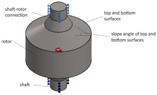
Figure 1.
Rotor parameters studied in the different models presented in Table 1.
Table 2 presents geometric and mass data for all models considered and their general configuration. The rotors are basically massive cylindrical bodies except for the case of Gaussian rotors, which have a disk shape. The material of all rotor models is Hexcel UHM Carbon Fibre 12000 with a von Mises tensile strength of 3730 MPa and specific mass of 1870 kg/m3 [13]. The parameters of the Gaussian shape rotors are like those defined by Stodola [19] for disk rotors with uniform stress.
Table 2.
Geometric and mass data for the flywheel models.
To obtain the rotor von Mises stress under rotation, we used the software SolidWorks Simulation 2016 and SolidWorks Motion based on the finite element method [16]. The allowable maximum rotation speed that defines the maximum rotor energy storage capability is the one associated with the maximum von Mises stress present in the rotor material just below failure [16]. The characteristics of the finite element method simulation with the SolidWorks software are static analysis, solid type of meshing, thermal effect activated, centrifugal load type, and bearing connector support type.
3. Results and Discussion for a Flywheel Single Rotor
We divided the analysis for increasing the storage energy capacity of flywheels as described in Table 1. In the first part, the analyses included (1) a means to reduce localized stresses, (2) an assessment of the impact of the shaft diameter, (3) an assessment of the impact of the slope angle on the top and bottom rotor surfaces, (4) an assessment of the impact of varying slope on the top and bottom rotor surfaces, and (5) an assessment of Gaussian rotors. In the second part, we analysed alternative designs to increase the storage energy capacity of Gaussian rotors. All stress analyses were performed as described in Section 2.
Table 3 summarizes the results for models A to R, presenting the maximum rotation achieved, system mass, stored energy, and energy density. The maximum rotation speed caused maximum stress just below that of the material (3739 MPa). In what follows, we present the results of stress distribution for each model and discuss the impact of different geometric design changes on the energy storage capacity of flywheels.
Table 3.
Results of the simulations for different flywheel models. The best results are bolded.
3.1. Means to Reduce Localized Stresses—Models A and B
Models A and B are similar but with a rounding surface added to Model B at the shaft/rotor connection for decreasing localized stresses. Figure 2 shows the stress distribution of both models.
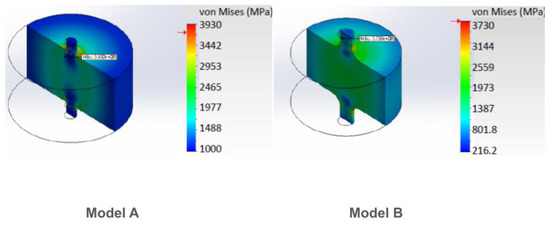
Figure 2.
Stress distribution for models A and B.
The increment in rotational speed expected by introducing a circular connection between the disk and the shaft (a radius) was not achieved. This procedure appeared to distribute the stress over the rotor body but did not reduce localized stresses. The energy storage capacity of model A was superior to that of model B, as shown in Table 3.
3.2. Impact of Shaft Diameter—Models C, D, and E
Models C, D, and E had similar dimensions except for those of the shaft radius, which were 30 mm, 50 mm, and 60 mm, respectively, as shown in Table 2. Figure 3 presents the stress distribution obtained for the condition just below the limit of the material.
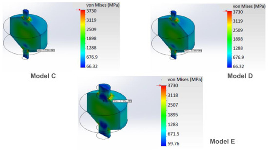
Figure 3.
Stress distribution for models C, D, and E with different shaft diameters.
Analysing Figure 3, one sees that, in model D, the stress distribution was increased in the central part of the rotor body. The results for these models, in Table 3, showed that model D produced the highest rotation speed, stored energy, and energy density. It stored more energy than Model E, which had a greater shaft radius. It shows that there was an optimal shaft radius for storing energy, which depends on the shaft/rotor system dimensions.
3.3. Impact of the Slope Angle on Top and Bottom Rotor Surfaces—Models F, G, H, I, J, and K
Models F to K had similar dimensions except for the slope angles on the top and bottom rotor surfaces, which varied from 20 to 45 degrees, as shown in Table 2. Figure 4 presents the stress distribution obtained for the condition just below the limit of the material.
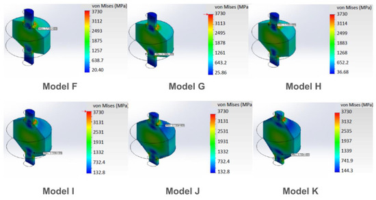
Figure 4.
Stress distribution for models F, G, H, I, J, and K with different slope angles for top and bottom surfaces.
Regarding stress distribution over the shaft/rotor system, one notices that Model H presented higher stress values in its central part compared to the other models in Figure 4. It seems that there was a favourable slope angle regarding stress distribution over the system around 30 degrees. This tendency is confirmed when we observe the results regarding rotation speed, stored energy, and energy density in Table 3. Model H presented the highest values for all these variables and had less system mass than models I, J, and K.
3.4. Impact of Varying Slope on Top and Bottom Rotor Surfaces—Models M, N, O, P, and Q
It was observed in the previous section that the slope was important for determining the maximum energy storage capacity of flywheels. In this section, we investigate varying slopes as a function of the rotor radius as described in Table 1 and Table 2, and Appendix A. Figure 5 presents the stress distribution for models M to Q, with M, N, and O models having different designs with two slopes, model P having five different slopes, and model Q having a continuously varying slope.
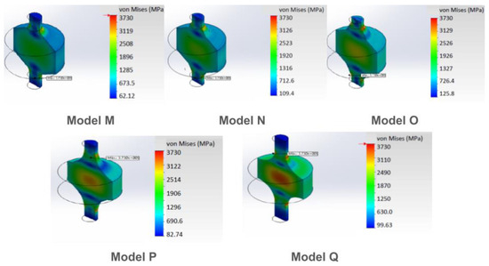
Figure 5.
Stress distribution for models M, N, O, P, and Q with different varying slope conditions for top and bottom surfaces.
Analysing models M, N, and O, we observed that the intervention in the basic rotor to allow two slopes varied their mass. The mass of the model increased from model M to model O. The maximum rotation, the stored energy, and so the energy density increased in the same direction. The start of the slope on model M happened at a height of 209.64 mm, in model N it happened at 232.64 mm, and it started on model O at 255.66 mm.
As the characteristics increased towards a more homogeneous curve, model P was designed with five slopes, as can be seen in Table 2. That shape decreased the mass and increased maximum rotation, stored energy, and energy density. It also increased the von Mises stress distribution, implying that a better shape will be the one with a constant von Mises stress.
Following the sequence of changes in the geometry, one concludes that the best outcome results from the geometry that makes the stress become more homogeneous in the rotor. It seems reasonable that the best result will be reached if the whole section of the rotor experiences maximum stress. As the authors intended to use a shape that allows the presence of bearings at both ends of the flywheel axle, the idea of using a similar shape for the Laval disks appeared. Then, a similar shape was tested, with the formula for the radius (R) given by:
where, as before, the mass density is ρ, the rotational velocity is ω, the tensile strength of the material is σ, and, now, with R0 being the radius at the centre of the thickness (t). This problem is solved by a rotor with a Gaussian shape, such as the one seen in Figure 6 in model R.
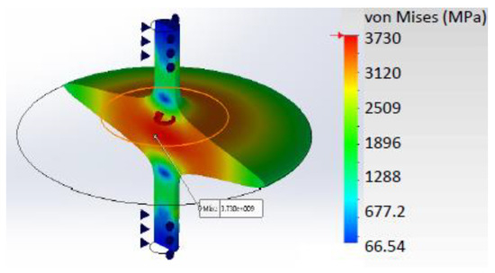
Figure 6.
The R model in a colour scale that gives the von Mises stress in Pa. Source: the authors.
For model R, the value found for K (the shape coefficient) was 0.7, in the range of the real Laval flywheel disks. The model seemed to be similar to the real Laval disks since there was room for improvement, which confirmed the shape choice. The next step, then, was to increase the energy density, adding some mass to the disk’s edge.
3.5. Adding Mass to the Rotor’s Edge
The next step to enhance the energy density in the rotor was to add some mass to the rotor. As can be seen in Figure 6, the von Mises stress at the rotor’s edge was low because there was almost no mass on the very edge to create significant centrifugal force. Therefore, adding mass to the extremities was expected to generate more force. In Figure 7, the new design is presented, with mass added to the rotor’s edge and the masses having a diamond cross section; the model will be named after the dimensions of this diamond cross section. Table 4 shows the results.
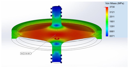
Figure 7.
Von Mises stresses for the R model with added mass at the rotor’s edge. Source: the authors.
Table 4.
Results of flywheel simulations with added mass to the rotors’ edges. The second column shows the maximum rotational speed in rpm. The identification is D-15 × 5, meaning a rotor with a diamond-shaped rim with a 15 mm vertical dimension and a 5 mm horizontal dimension. The maximum values are bolded.
4. Double and Triple Flywheel Rotors
Flywheel rotors’ masses are small, yielding an equally small total stored energy. In order to increase this energy storage, the model was modified to include three or two rotors, Gaussian in shape. In Figure 8, the flywheel has a double Gaussian rotor; in Figure 9, the flywheel has a triple Gaussian rotor. Table 5 displays an example of total energy, maximum rotation, total mass, and energy density for such a rotor that is triple Gaussian.
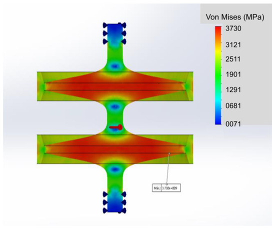
Figure 8.
Example of a double rotor flywheel. Source: the authors.
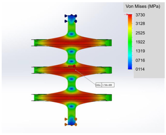
Figure 9.
Example of a triple rotor flywheel. Source: the authors.
Table 5.
Relevant values for an instance of a triple rotor.
5. Vibration Modes’ Analyses for Stability
For rotors at very high rotational speeds, stability is of great concern. The spinning rotor experiences shape changes that originate torques, which, in turn, could excite the rotor vibrational normal modes. In the case of resonance, the vibration could damage the rotor and the flywheel.
In order to avoid this problem, the flywheels’ normal modes were simulated to determine their frequencies. Figure 10 shows an example that is characterised by the masses added to the edges of the Gaussian rotor, which vibrate up and down in the system’s axial direction and whose first normal mode is around 0.086 Hz. This mode is very inconvenient because all of the harmonics of this frequency are expected to resonate with this rotation torque. The masses at the edges do not allow a satisfactory increase in energy density. Consequently, they were withdrawn from this flywheel and all remaining flywheel rotors were then formed solely by the Gaussian-shaped ring. In Figure 11, the vibration mode of a double rotor can be seen with Gaussian disks only, and no vibration is present.
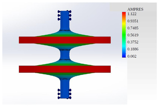
Figure 10.
A double rotor in its first vibration mode. Source: the authors.
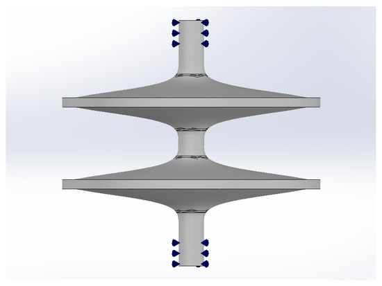
Figure 11.
A double rotor with Gaussian disks only. As it spins, the zero frequency of vibration implies no vibration amplitudes. Source: the authors.
For the triple and double flywheel rotors, the normal modes were determined using simulations. The vibrational frequencies and the respective harmonics were avoided with the aid of the flywheel control system present in the electromechanical battery. This operation was achievable because there were few such modes in the working range of the flywheel. Figure 12 and Figure 13 show the results. The first normal mode of the double rotor had 1151 Hz, while a single rotor had this frequency at 3341 Hz. In both cases, normal modes existed in the operational range up to 4000 Hz.
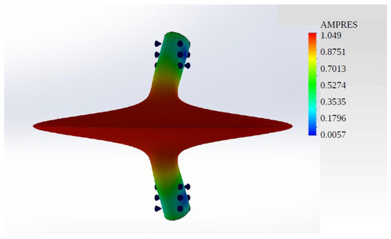
Figure 12.
A single rotor in its first and only normal mode. At a frequency of 3453 Hz, the operational range went up to 4000 Hz. Source: the authors.
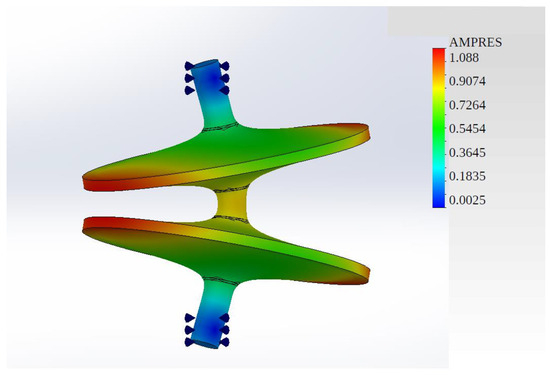
Figure 13.
A double rotor in its first and only normal mode. At a frequency of 1151 Hz, the operational range went up to 4000 Hz. Harmonics must be considered. Source: the authors.
The instability of the double rotor flywheel was avoided by adding a reinforcement to the connection between the two disks (Figure 14). The frequency of the first normal mode was calculated as 2500 Hz. By making the bearing axes shorter, it is possible to increase this frequency. However, this was not chosen in the simulation because the used length was necessary to allow the running of the simulation. Improvement is also possible by widening the reinforcement. Figure 15 shows such a reinforced double rotor, which presents 403 Wh/kg or 1.45 MJ/kg for the energy density. There is room for improvement because the maximum von Mises stress point was on the surface of the shaft’s Gaussian curve.
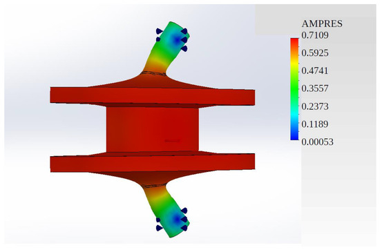
Figure 14.
Reinforced flywheel double rotor in its first and only 2500 Hz normal mode, increasing the operational frequency. Source: the authors.
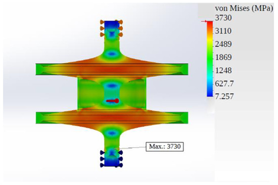
Figure 15.
The reinforced double rotor flywheel shown with a simulation of von Mises stress. Source: the authors.
Figure 16 shows the same simulation for the reinforced triple rotor, which presents the same value of 403 Wh/kg or 1.45 MJ/kg; Table 6 shows the values. There is room for improvement because the maximum von Mises stress point was on the surface of the support axis.
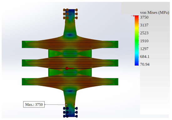
Figure 16.
The reinforced triple rotor flywheel shown with a simulation of von Mises stress. Source: the authors.
Table 6.
Relevant values for an instance of a triple reinforced rotor.
6. Conclusions and Future Work
A case study involving 18 flywheel rotors’ geometries was presented, with the determination of the energy density at maximum rotational speed with the aid of finite element modelling. The rotors were composed of carbon fibre Hexcel UHM 12000, and the following parameters were calculated: total stored energy, maximum rotational speed, energy density, and total mass. The von Mises stress was analysed in all models, for which the critical stress points were found. The extensive number of simulations allowed the authors to understand the simulation better.
This work uses a different shape to optimise the energy density, as given by Equation (4), compared to the other one in Equation (2). The difference between them is the presence of either the radius or the thickness in the exponential term, respectively. In a comparison with a real Laval disk, the results are compatible.
In regard to the total stored rotational energy, the highest value of 8381 kJ (2328 Wh) was found for model L. However, as this model presented a relatively large mass (10.731 kg), its energy density was low (781 kJ or 216.97 Wh/kg), in fact lower than the majority of the models investigated.
The model R had a rotor that was Gaussian-shaped and presented the highest specific energy for a single-rotor model (1393 kJ or 387 Wh/kg), as well as the largest rotational speed (279,180 rpm).
The triple rotor reached an energy density of 1552 kJ (431 Wh/kg), which gave a value for K of about 0.78. This value was within the range of K for the real Laval flywheel rotors. There are more resistant carbon fibres available on the market, but this work kept it constant to allow for comparisons.
This result shows that the choice of the geometry could increase the energy density of the flywheel, which is in agreement with the literature.
Analysing Equation (2), the perfect shape has a K equal to 1, which makes the von Mises stress reach its maximum in all volumes of the flywheel rotor. The Laval rotor can reach it, but this geometry is not real as its diameter goes to infinity when the thickness tends to 0. In order to avoid this problem, a cutoff is made at some diameter, which makes K vary from 0.7 to 0.9. Coincidentally, the best value for K found in this work was in this interval.
There is room for improvement as some parts of the rotors were not in the von Mises limit, but these regions were needed to run the simulation. One element of the future works is to try to run the simulation in a different way to eliminate this excess mass. Also, it is necessary to make some changes in the design of the reinforced triple rotor, as maximum von Mises stress is located in the shaft close to the bearings. Several changes were made but they were not successful in moving the location of this maximum stress.
It is worth emphasising that this work included the regions of the flywheel rotor needed to mount the bearing system in the same structure of the rotating disk, while the Laval disks would need to incorporate those.
Instability under rotation was also analysed. Possible instabilities were found due to normal rotational modes at the operational frequencies. These modes must be avoided in the operation of the flywheel, a process that can be implemented easily by a control system for the flywheel, capable of accelerating or decelerating the device as it passes through these frequencies. As these devices can work in pairs, one rotating in a clockwise direction and the other rotating in a counterclockwise direction (cancelling the total angular momentum), the control system can redirect energy from one flywheel to the other. This can be performed easily with the single rotor flywheel, as it has only one instability mode in the operational frequency range. The same does not happen with the double and triple rotors.
The triple and double rotors may have instability issues reduced through the adoption of a reinforcement tube to connect the Gaussian disks, one that does not degrade significantly the specific rotational energy. For instance, the reinforced double rotor presented an energy density of 1451 kJ (403 Wh/kg), which can also be enhanced.
A next step is to make the same procedure to increase the total energy but this time using Laval disks mounted in parallel.
The results of this work are references for future investigations on the next steps for manufacturing an actual flywheel, especially if they are made of CNT, which are made of very expensive materials. If these materials have enough resistance, the stored energy density can reach the same values of common liquid fuels, such as gasoline (taking into account their efficiencies).
In the case of carbon nanotubes, they could not be used because they could not be fabricated in long enough dimensions. The natural solution could be to use CNT in the form of laminates, such as carbon fibres. Another option is to wait for the development of better carbon fibres as their resistance is improving with time.
The next step of this work is to simulate the resistance of these flywheel rotors made of laminated CNT aligned in the radial direction, the direction where the stresses are higher.
Author Contributions
Conceptualization: C.F.; methodology: C.F. and F.d.S.B.; software: D.C.; validation: C.F. and D.C.; formal analysis: all authors; investigation: all authors.; resources: D.C.; writing—original draft preparation: C.F. and N.S.M.; writing—review and editing: N.S.M.; supervision: C.F. and F.d.S.B.; project administration: C.F. and J.M.L.M.; funding acquisition, C.F., F.d.S.B., and D.C. All authors have read and agreed to the published version of the manuscript.
Funding
This research was funded by FAPESP through grant #2013/26258-4 and by CNPq through grant #312454/2021-0. The APC was funded by vouchers.
Data Availability Statement
The original contributions presented in the study are included in the article, further inquiries can be directed to the corresponding author.
Conflicts of Interest
The authors declare no conflicts of interest.
Appendix A
The list of first simulations involves bodies that are solid and cylindrical, generally displaying 200 mm of external diameter, approximately 100 mm in height. In Figure A1, Figure A2 and Figure A3. The models are indicated by letters as follows.
- Model A:
Solid, cylindrical, carbon fibre body with an external diameter of 200 mm, a height of 120 mm from the centre of the cylinder to a radius of 15 mm (shaft configuration), and a height of 100 mm from a radius of 15 mm to an external diameter of 200 mm (disk shaping). The model presents longitudinal and transverse symmetries (Figure 3). This model showed that the stresses increase towards the radius outside the axis, reaching the critical point where the axis meets the disk surface (Figure 3). The concentration of stress in this section constrained the investigation to a maximum value of rotation of 162,180 rpm.
- Model B:
Solid, cylindrical, carbon fibre body with an external diameter of 200 mm, a height of 120 mm from the centre of the cylinder to a radius of 15 mm (shaft configuration). A height of 100 mm from this radius to the external diameter of 200 mm, with the introduction of a radius in the connection between the shaft and the disk (shaft shaping). External diameter height of 100 mm. The purpose of introducing this radius was to alleviate the concentration of stresses arising where the axis meets the surface of the disk observed in Model A. The model presents longitudinal and transverse symmetries (Figure 3). This model showed the stresses increasing towards the radius external to the axis more homogeneously, until they reached the critical point where the radius met the axis (Figure 3). The increment in rotational speed expected by introducing the radius was not achieved because the stress concentration in this section constrained the investigation to a maximum value of rotation of 153,380 rpm.
- Model C:
Solid, cylindrical, carbon fibre body with an external diameter of 200 mm, a height of 270 mm from the centre of the cylinder to a radius of 15 mm (shaft shape), and a height of 198.15 mm from this radius, forming an angle of 30° perpendicular to the axis, up to an external diameter of 200 mm (disk shape); external diameter height of 100 mm. The model presents longitudinal and transversal symmetries (Figure 3). This model presented tensions distributed homogeneously throughout its body with an accumulation of these tensions near the intersection between the axis and the disk surface (Figure 3). The concentration of stress in this section constrained the investigation to a maximum value of speed of 166,580 rpm.
- Model D:
Solid, cylindrical, carbon fibre body with an external diameter of 200 mm, a height of 270 mm from the centre of the cylinder to a radius of 25 mm (shaft shape), and a height of 186.60 mm from this radius, forming an angle of 30° perpendicular to the axis, up to an external diameter of 200 mm (disk shape); external diameter height of 100 mm. The model presents longitudinal and transversal symmetries (Figure 3). This model presented tensions distributed homogeneously throughout its body with an accumulation of these tensions near the intersection between the axis and the disk surface (Figure 3). The concentration of stress in this section constrained the investigation to a maximum value of rotation of 192,340 rpm.
- Model E:
Solid, cylindrical, carbon fibre body with an external diameter of 200 mm, a height of 270 mm from the centre of the cylinder to a radius of 30 mm (shaft shape), and a height of 180.82 mm from this radius, forming an angle of 30° perpendicular to the axis, up to an external diameter of 200 mm (disk shape); external diameter height of 100 mm. The model presents longitudinal and transversal symmetries (Figure 3). This model presented tensions distributed as in the previous model: homogeneous throughout its body, with an accumulation of these tensions near the intersection between the axis and the disk surface (Figure 3). The concentration of stress in this section constrained the investigation to a maximum value of rotation of 185,520 rpm.
- Model F:
Solid, cylindrical, carbon fibre body with an external diameter of 200.00 mm, a height of 300.00 mm from the centre of the cylinder to a radius of 25.00 mm (shaft shape), and a height of 154.60 mm from this radius, forming an angle of 20° perpendicular to the axis, up to an external diameter of 200 mm (disk shape); external diameter height of 100 mm. The model presents longitudinal and transversal symmetry (Figure 4). This model presented the tensions distributed homogeneously in the central part of the body and a slight tendency to grow towards the centre. The lowest stresses were found near the axis, both above and below the area where the axis intersects the disk surface, which is a region where an accumulation of stresses occurs (Figure 4). The concentration of stress in this section constrained the investigation to a maximum value of rotation of 187,150 rpm.
- Model G:
Solid, cylindrical, carbon fibre body with an external diameter of 200 mm, a height of 300 mm from the centre of the cylinder to a radius of 25 mm (shaft shape), and a height of 169.94 mm from this radius, forming an angle of 25° perpendicular to the axis, up to an external diameter of 200 mm (disk shape); external diameter height of 100.00 mm. The model presents longitudinal and transversal symmetries (Figure 4). This model presented stresses distributed as in the previous model, with an accumulation of these stresses near the intersection between the axis and the disk surface (Figure 4). The concentration of stress in this section constrained the investigation to a maximum value of rotation of 191,980 rpm.
- Model H:
Solid, cylindrical, carbon fibre body with an external diameter of 200 mm, a height of 300 mm from the centre of the cylinder to a radius of 25 mm (shaft shape), and a height of 186.60 mm from this radius, forming an angle of 30° perpendicular to the axis, up to an external diameter of 200 mm (disk shape); external diameter height of 100 mm. The model presents longitudinal and transversal symmetries (Figure 4). This model presented stresses distributed as in the previous model, with an accumulation of these stresses near the intersection between the axis and the disk surface (Figure 4). The concentration of stress in this section constrained the investigation to a maximum value of rotation of 194,330 rpm.
- Model I:
Solid, cylindrical, carbon fibre body with an external diameter of 200.00 mm, a height of 300 mm from the centre of the cylinder to a radius of 25.00 (shaft shape), and a height of 205.04 mm from this radius, forming an angle of 35° perpendicular to the axis, up to an external diameter of 200 mm (disk shape); external diameter height of 100 mm. The model presents longitudinal and transversal symmetries (Figure 4). This model presented stresses distributed as in the previous model, with an accumulation of these stresses near the intersection between the axis and the disk surface (Figure 4). The concentration of stress in this section constrained the investigation to a maximum value of rotation of 185,070 rpm.
- Model J:
Solid, cylindrical, carbon fibre body with an external diameter of 200 mm, a height of 300 mm from the centre of the cylinder to a radius of 25 mm (shaft shape), and a height of 225.86 mm from this radius, forming an angle of 40° perpendicular to the axis, up to an external diameter of 200 mm (disk shape); external diameter height of 100 mm. The model presents longitudinal and transversal symmetries (Figure 4). This model presented stresses distributed as in the previous model, with an accumulation of these stresses near the intersection between the axis and the disk surface (Figure 4). The concentration of stress in this section constrained the investigation to a maximum value of rotation of 185,700 rpm.
- Model K:
Solid, cylindrical, carbon fibre body with an external diameter of 200 mm, a height of 300 mm from the centre of the cylinder to a radius of 25 mm (shaft shape), and a height of 250 mm from this radius, forming an angle of 45° perpendicular to the axis, up to an external diameter of 200.00 mm (disk shape); external diameter height of 100 mm. The model presents longitudinal and transversal symmetries (Figure 5). This model presented stresses distributed as in the previous model, with an accumulation of these stresses near the intersection between the axis and the disk surface (Figure 5). The concentration of stress in this section constrained the investigation to a maximum value of rotation of 182,130 rpm.
- Model M:
Solid, cylindrical, carbon fibre body with an external diameter of 200 mm, a height of 300 mm from the centre of the cylinder to a radius of 25 mm (shaft shape), and a height of 209.64 mm from this radius, forming an angle of 60° perpendicular to the axis, up to a height of 175 mm (this point must be 10 mm perpendicular to the line of extension of the projection of the axis surface). From this height, forming an angle of 30° perpendicular to the axis up to the external diameter of 200 mm (disk shape). External diameter height of 100 mm. The model presents longitudinal and transversal symmetries (Figure 5). This model presented the tensions distributed homogeneously in the central part of the body and a slight tendency to grow towards the centre. Lower stresses were found along the axis, both above and below the area where the axis intersects the surface of the disk, a region where the accumulation of stresses occurs (Figure 5). The concentration of stress in this section constrained the investigation to a maximum value of rotation of 162,920 rpm.
- Model N:
Solid, cylindrical, carbon fibre body with an external diameter of 200 mm, a height of 300 mm from the centre of the cylinder to a radius of 25 mm (shaft shape), and a height of 232.74 mm from this radius. An angle of 60° is formed perpendicular to the axis, up to a height of 163.46 mm (this point must be 20 perpendicular to the line of extension of the projection of the axis surface). From this height, forming an angle of 30° perpendicular to the axis up to the external diameter of 200 mm (disk shape). External diameter height of 100 mm. The model presents longitudinal and transversal symmetries. This model presented stresses distributed as in the previous model, with an accumulation of these stresses near the intersection between the axis and the disk surface (Figure 5). The concentration of stress in this section constrained the investigation to a maximum value of rotation of 175,880 rpm.
- Model O:
Solid, cylindrical, carbon fibre body with an external diameter of 200 mm, a height of 300 mm from the centre of the cylinder to a radius of 25 mm (shaft shape), and a height of 255.66 mm from this radius, forming an angle of 60° perpendicular to the axis, up to a height of 151.74 mm (this point must be 30 mm perpendicular to the line of extension of the projection of the axis surface). From this height, forming an angle of 30° perpendicular to the axis up to the external diameter of 200 mm (disk shape). External diameter height of 100 mm. The model presents longitudinal and transversal symmetries. This model presented stresses distributed as in the previous model, with an accumulation of these stresses near the intersection between the axis and the disk surface (Figure 5). The concentration of stress in this section constrained the investigation to a maximum value of rotation of 189,900 rpm.
- Model P:
Solid, cylindrical, carbon fibre body with an external diameter of 200 mm, a height of 400 mm from the centre of the cylinder to a radius of 25 mm (shaft shape), and a height of 266.22 mm from this radius, forming an angle of 70° parallel to the axis, up to a height of 180.22 mm (this point must be 15 mm perpendicular to the line of extension of the projection of the axis surface). From that height, forming an angle of 60° perpendicular to the axis up to a height of 128.26 mm (this point must be 30 mm perpendicular to the line of extension of the projection of the axis surface). From that height, forming an angle of 50° perpendicular to the axis up to a height of 92.5 mm (this point must be 45 mm perpendicular to the line of extension of the projection of the axis surface). From that height, forming an angle of 40° perpendicular to the axis up to a height of 67.32 mm (this point must be 60 mm perpendicular to the line of extension of the projection of the axis surface). From that height, forming an angle of 30° perpendicular to the axis up to the external diameter of 200 mm (disk conformation). Height of the external diameter, 100 mm. This model presents longitudinal and transverse symmetries (Figure 6). It also presented a homogeneous distribution of intermediate tensions throughout the body with their growth moving in the direction of the central region. Lower stresses were found at the ends of the axis as well as between the centre and the area where the model surface intersects the axis, a region where stress accumulation occurs (Figure 6). The concentration of stress in this section constrained the investigation to a maximum value of rotation of 195,440 rpm.
- Model Q:
Solid, cylindrical, carbon fibre body with an external diameter of 200 mm, a height of 400 mm from the centre of the cylinder to a radius of 25 mm (shaft shape), and a height of 170 mm from this radius. An arc is formed, with a radius 35 mm, with a centre equidistant from the symmetry axes (horizontal and vertical) of the model, tangential to the axis and the surface of the model (conformation of the disk). External diameter height of 100 mm. The model presents longitudinal and transversal symmetries (Figure 6). This model presented a stress distribution similar to the previous one, displaying a greater increase towards the smaller-volume region at the centre. An accumulation of stress was observed where the axis intersects the surface of the model (Figure 6). The concentration of stress in this section constrained the investigation to a maximum value of rotation of 204,820 rpm.
The Q model performed better, displaying higher rotation speed as well as higher energy density. It thus indicated that, to enhance the energy density, the model had to present a distribution in tensile stress as uniform as possible. Consequently, a model with 180 mm of external diameter and 130 mm of height was developed, with its shape determined by the revolution of a Gaussian curve, which created the model R.

Figure A1.
The models A, B, C, D, and E for flywheels are shown. Blue arrows show where the connector/support of the flywheel is located in the FEM simulation. The colour scale gives the von Mises stress in Pa. Source: the authors.
Figure A1.
The models A, B, C, D, and E for flywheels are shown. Blue arrows show where the connector/support of the flywheel is located in the FEM simulation. The colour scale gives the von Mises stress in Pa. Source: the authors.


Figure A2.
The models F, G, H, I, and J for flywheels are shown. Blue arrows show where the connector/support of the flywheel is located in the FEM simulation. The colour scale gives the von Mises stress in Pa. Source: the authors.
Figure A2.
The models F, G, H, I, and J for flywheels are shown. Blue arrows show where the connector/support of the flywheel is located in the FEM simulation. The colour scale gives the von Mises stress in Pa. Source: the authors.


Figure A3.
The models K, M, N, and O for flywheels are shown. Blue arrows show where the connector/support of the flywheel is located in the FEM simulation. The colour scale gives the von Mises stress in Pa. Source: the authors.
Figure A3.
The models K, M, N, and O for flywheels are shown. Blue arrows show where the connector/support of the flywheel is located in the FEM simulation. The colour scale gives the von Mises stress in Pa. Source: the authors.


Figure A4.
The models P, Q, and R for flywheels are shown. Blue arrows show where the connector/support of the flywheel is located in the FEM simulation. The colour scale gives the von Mises stress in Pa. Source: the authors.
Figure A4.
The models P, Q, and R for flywheels are shown. Blue arrows show where the connector/support of the flywheel is located in the FEM simulation. The colour scale gives the von Mises stress in Pa. Source: the authors.

References
- Mutarraf, M.U.; Terriche, Y.; Niazi, K.A.K.; Vasquez, J.C.; Guerrero, J.M. Energy Storage Systems for Shipboard Microgrids—A Review. Energies 2018, 11, 3492. [Google Scholar] [CrossRef]
- Xu, K.; Guo, Y.; Lei, G.; Zhu, J. A Review of Flywheel Energy Storage System Technologies. Energies 2023, 16, 6462. [Google Scholar] [CrossRef]
- Zhao, J.; Gu, Z.; Li, B.; Liu, X.; Li, X.; Chen, Z. Research on the Torque and Back EMF Performance of a High Speed PMSM Used for Flywheel Energy Storage. Energies 2015, 8, 2867–2888. [Google Scholar] [CrossRef]
- Ji, W.; Hong, F.; Zhao, Y.; Liang, L.; Du, H. Applications of Flywheels Energy Storage System on Load Frequency Regulation Combined with Power Generations: A review. Renew. Energy 2024, 223, 119975. [Google Scholar] [CrossRef]
- Fiske, O.J.; Ricci, M.R. Third Generation Flywheels For High Power Electricity Storage; LaunchPoint Technologies, Inc.: Goleta, CA, USA, 2016; Available online: https://www.launchpnt.com/hs-fs/hub/53140/file-14467597-pdf/docs/002_fiske_powerring.pdf (accessed on 1 August 2023).
- Kale, V.; Aage, N.; Secannel, M. Stress constrained topology optimization of energy storage flywheels using a specific energy formulation. J. Energy Storage 2023, 61, 106733. [Google Scholar] [CrossRef]
- Bankston, S.; Mo, C. Geometry Modification of Flywheels and its Effect on Energy Storage. Energy Res. J. 2015, 6, 54. [Google Scholar] [CrossRef][Green Version]
- IRENA (International Renewable Energy Agency). Electricity Storage and Renewables: Costs and Markets to 2030; International Renewable Energy Agency: Masdar, United Arab Emirates, 2017; p. 58. [Google Scholar]
- Ribeiro, M.R. Sistema Armazenador de Energia Cinética SAEC—Estratégia de Controle e Simulações. Master’s Thesis, Instituto Alberto Luiz Coimbra de Pós-Graduação e Pesquisa em Engenharia, The Federal University of Rio de Janeiro (UFRJ), Rio de Janeiro, Brazil, 2008. [Google Scholar]
- Fowler, T.K.; Post, R.F. Mechanical Stability of Multiple-Shell Energy Storage Rotors. In Proceedings of the Western Applied Mechanics Conference, Hampton, VA, USA, 18–21 June 1973. [Google Scholar]
- Post, R.F.; Fowler, T.K.; Post, S.F. A high-efficiency electromechanical battery. Proc. IEEE 1993, 81, 462–474. [Google Scholar] [CrossRef]
- Shi, C.; Wei, T.; Tang, X.; Zhou, L.; Zhang, T. Charging–Discharging Control Strategy for a Flywheel Array Energy Storage System Based on the Equal Incremental Principle. Energies 2019, 12, 2844. [Google Scholar] [CrossRef]
- Rocca, R.; Papadopoulos, S.; Rashed, M.; Prassinos, G.; Capponi, F.G.; Galea, M. Design Trade-Offs and Feasibility Assessment of a Novel One-Body, Laminated-Rotor Flywheel Switched Reluctance Machine. Energies 2020, 13, 5857. [Google Scholar] [CrossRef]
- Toh, C.-S.; Chen, S.-L. Design, Modeling and Control of Magnetic Bearings for a Ring-Type Flywheel Energy Storage System. Energies 2016, 9, 1051. [Google Scholar] [CrossRef]
- Sonsky, J.; Tesar, V. Design of a stabilised flywheel unit for efficient energy storage. J. Energy Storage 2019, 24, 100765. [Google Scholar] [CrossRef]
- Choudhury, S. Flywheel Energy Storage Systems: A Critical Review on Technologies, Applications, and Future Perspectives. Int. Trans. Electr. Energy Syst. 2021, 31, e13024. [Google Scholar] [CrossRef]
- Okou, R.; Sebitosi, A.B.; Pillay, P. Flywheel rotor manufacture for rural energy storage in sub-Saharan Africa. Energy 2011, 36, 6138–6145. [Google Scholar] [CrossRef]
- Rupp, A.; Baier, H.; Mertiny, P.; Secanell, M. Analysis of a flywheel energy storage system for light rail transit. Energy 2016, 107, 625–638. [Google Scholar] [CrossRef]
- Sun, B.; Li, B.; Xing, J.; Yu, X.; Xie, M.; Hu, Z. Analysis of the influence of electric flywheel and electromechanical flywheel on electric vehicle economy. Energy 2024, 295, 131069. [Google Scholar] [CrossRef]
- Bakkari, F.E.; Mounir, H. Compatible alternative energy storage systems for electric vehicles: Review of relevant technology derived from conventional systems. Energy 2024, 288, 129775. [Google Scholar] [CrossRef]
- Cronk, P.; van de Ven, J.; Strohmaier, K. Design optimization, construction, and testing of a hydraulic flywheel accumulator. J. Energy Storage 2021, 44, 103281. [Google Scholar] [CrossRef]
- Kress, G.R. Shape optimization of a flywheel. Struc. Multidiscip. Optim. 2000, 19, 74. [Google Scholar] [CrossRef]
- Ertz, G.; Twiefel, J.; Krack, M. Feasibility Study for Small Scaling Flywheel-Energy-Storage Systems in Energy Harvesting Systems. Energy Harvest. Syst. 2014, 1, 233–241. [Google Scholar] [CrossRef]
- Hedlund, M.; Lundin, J.; de Santiago, J.; Abrahamsson, J.; Bernhoff, H. Flywheel Energy Storage for Automotive Applications. Energies 2015, 8, 10636. [Google Scholar] [CrossRef]
- Ashby, M.F. Materials Selection in Mechanical Design, 5th ed.; Elsevier Ltd.: Cambridge, MA, USA, 2017. [Google Scholar]
- Bai, Y.; Shen, B.; Zhang, S.; Zhu, Z.; Sun, S.; Gao, J.; Li, B.; Wang, Y.; Zhang, R.; Wei, F. Storage of Mechanical Energy Based on Carbon Nanotubes with High Energy Density and Power Density. Adv. Mater. 2019, 31, 1800680. [Google Scholar] [CrossRef] [PubMed]
- MatWeb—The Online Materials Information Resource. Available online: http://www.matweb.com (accessed on 1 August 2023).
- Bortoli, F.S.; Frajuca, C.; Magalhaes, N.S.; Duarte, E.N. A physical criterion for validating the method used to design mechanical impedance matchers for Mario Schenberg’s transducers. J. Phys. Conf. Ser. 2010, 228, 012001. [Google Scholar] [CrossRef]
- Nogueira, P.R.M. Otimização de Geometria e Material para Baterias Eletromecânicas. Master’s Thesis, The Federal Institute of São Paulo, Sao Paulo, Brazil, 2016. [Google Scholar]
- SOLIDWORKS. 2016. Available online: https://www.solidworks.com (accessed on 1 August 2023).


Disclaimer/Publisher’s Note: The statements, opinions and data contained in all publications are solely those of the individual author(s) and contributor(s) and not of MDPI and/or the editor(s). MDPI and/or the editor(s) disclaim responsibility for any injury to people or property resulting from any ideas, methods, instructions or products referred to in the content. |
© 2024 by the authors. Licensee MDPI, Basel, Switzerland. This article is an open access article distributed under the terms and conditions of the Creative Commons Attribution (CC BY) license (https://creativecommons.org/licenses/by/4.0/).