Abstract
Based on a constant volume combustion chamber, the initial ambient pressure effect on gasoline combustion performance and flame propagation of the active and passive pre-chamber ignition systems were studied. Compared with the passive pre-chamber, the active pre-chamber can significantly expand the lean combustion limit from 1.2 to 1.5, enhance the ignition and combustion performance, and speed up the combustion of the main combustion chamber. At slightly lean combustion conditions, the heat release performance has a positive correlation with the initial ambient pressure. As the premixed λ increases, the heat release performance and the initial ambient pressure begin to become negatively correlated. Ignition delay can be decreased by approximately 50% at an initial pressure of 0.75 MPa, premixed lambda of 1.2 with APC compared with PPC. The high ambient pressure (1.0 MPa) in the constant volume chamber greatly reduces the mixture entrainment ability of the jet flame at lean combustion conditions, thereby reducing the combustion speed and peak heat release rate.
1. Introduction
Under the target of “Carbon Peak” and “Carbon Neutral”, hybrid electric vehicles (HEV) are increasingly favored by enterprises and consumers because of their fuel–electric synergistic technology, which offers good fuel efficiency and low emissions while considering the range of vehicles. Compared with stoichiometric combustion, lean combustion can improve the specific heat ratio of the mixture [1,2,3,4], resulting in improved engine thermal efficiency. Still, it faces the challenges of ignition difficulty and low flame propagation. The pre-chamber ignition system is recognized as one of the most reliable methods to achieve lean combustion [5].
The existing pre-chamber jet ignition method includes active pre-chamber and passive pre-chamber, while the active pre-chamber has been proved to achieve ultra-lean mixture combustion with lambda (λ) greater than 2.0 [6]. Compared with the active pre-chamber, the passive pre-chamber does not significantly improve the lean combustion limit [7]. This is mainly due to insufficient scavenging inside the pre-chamber, making it difficult for the mixture near the spark plug electrode to achieve optimal ignition conditions. At the same time, the peak temperature of the mixture after ignition is relatively low at lean combustion conditions; the NOx emissions will be significantly reduced [8,9], even closing the zero level (<10 ppm) [10]. According to research by Jamrozik et al. [6], it could achieve a small non-repeatability of cycles and low NOX emissions ultra-lean combustion.
Changes in engine load mainly affect the ambient density and pressure inside the cylinder, which directly affect the flame propagation in the space. The in-cylinder flame formed by jet ignition propagates is similar to the fuel–air entrainment of the premix combustion [11]. The turbulent flame front induced by the jet flame develops outward and consumes the surrounding mixture. The amount of jet flame entrainment is the main factor affecting jet ignition performance [12]. The speed of the jet flame will increase as the ambient pressure increases [13], but it will not significantly affect the laminar flame stability [14]. Meanwhile, the low-flow injection inside the pre-chamber is mainly determined by injection pressure, timing, and duration. Building a mixture with a suitable equivalence ratio distribution in the pre-chamber before the spark plug ignition is the prerequisite for optimizing jet ignition performance. Chunhuan Zhang [15] designed an active pre-chamber ignition system for a large gas-fueled engine. The fuel mixing process in the pre-combustion chamber and the propagation process of the jet flame in the pre-chamber and the main combustion chamber were analyzed. Meanwhile, the effects of the injection strategies of the pre-chamber on the combustion of the system were investigated. It was found that the combustion period in the pre-chamber was the shortest when the equivalent ratio of the pre-chamber was in the range of 1.04–1.11.
In this paper, based on a constant volume combustion chamber (CVCC), the influence of different initial ambient pressures and lambda on flame propagation and the combustion characteristics of active/passive pre-chamber (APC/PPC) were studied.
2. Experimental Setup
2.1. Pre-Chamber Design and Experiment Operating Conditions
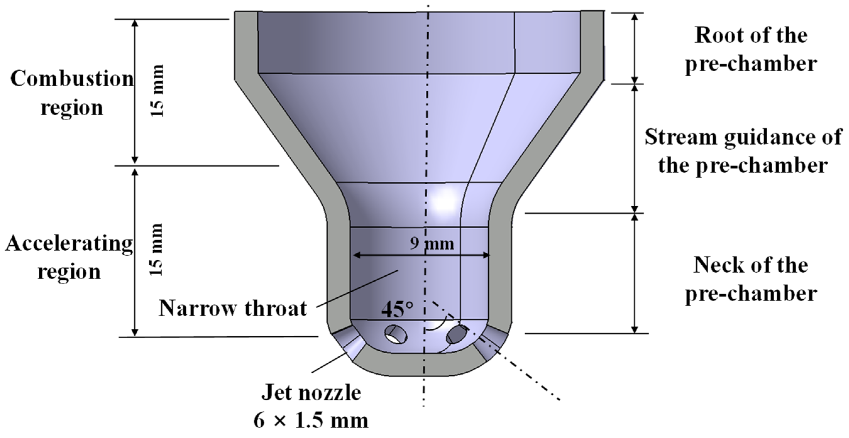
Figure 1 shows the schematic of the pre-chamber (PC) with a narrow bottom and six jet nozzles, forming an angle of 45° with the horizontal direction. The total volume in the pre-chamber is about 2.7 cm3.
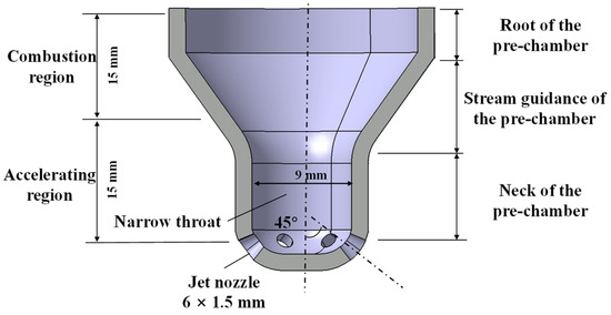
Figure 1.
Pre-chamber structure design.
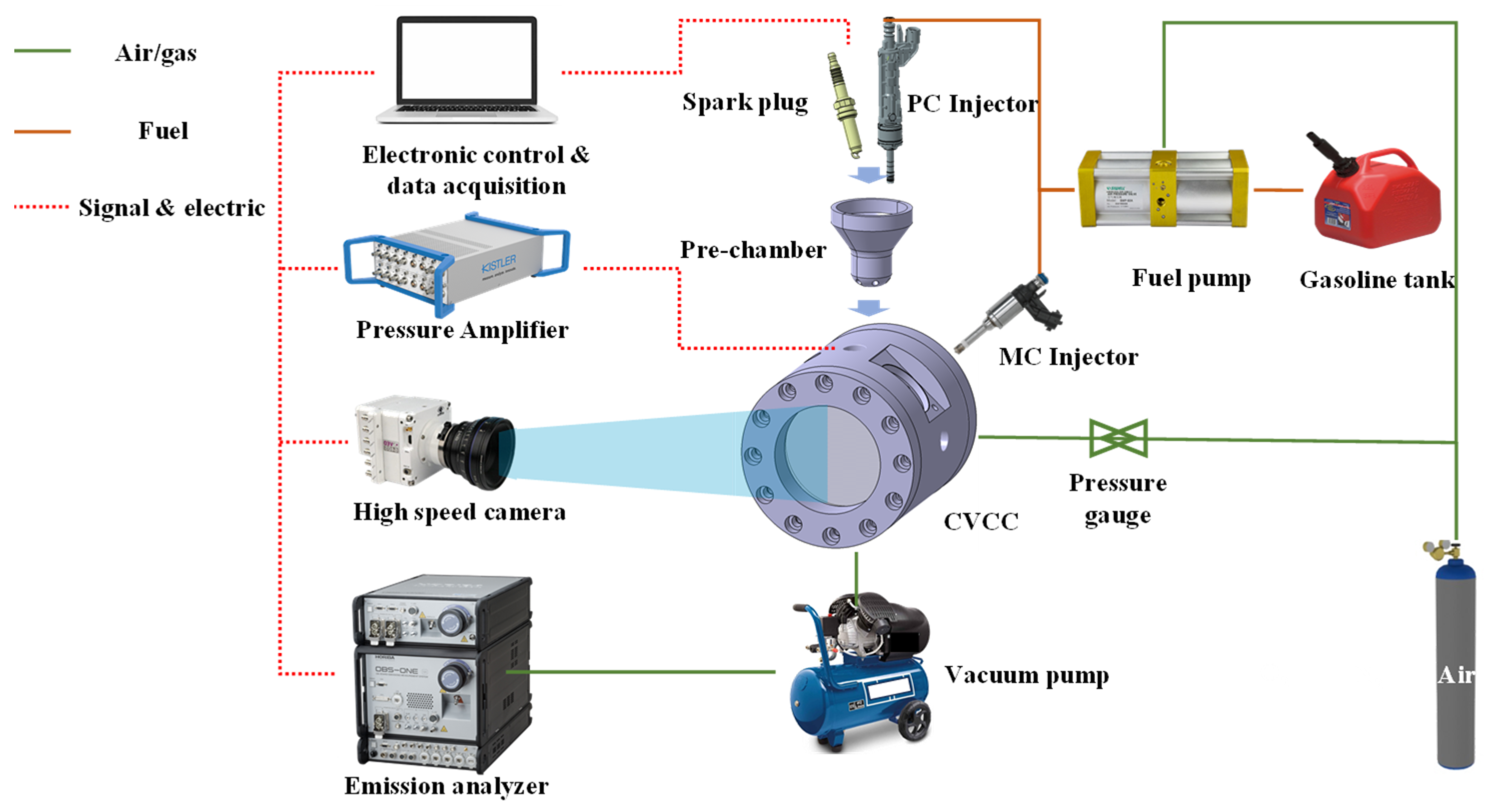
Figure 2 shows the constant volume combustion chamber system, including a cylindrical CVCC, high-pressure gasoline injection system, spark ignition system, high-frequency pressure measurement system, and high-speed photography system. The combustion chamber of the CVCC is a horizontal Φ 80 × 132 mm cylinder. One end of the CVCC is equipped with optical quartz glass, and the other end is equipped with a steel cover installed in the pre-chamber. The CVCC is equipped with a heating system, which could be used to heat the combustion chamber.

Figure 2.
CVCC experiment system layout.
The control system of ignition and injection was developed in-house using NI Compact RIO and LabVIEW. The pressure data acquisition system consists of a pressure sensor (Kistler 6115CF-4CQ07-4-1, Kistler, Shanghai, China), a charge amplifier (Kistler 5064, Kistler, Shanghai, China), and a computer with a data acquisition LabVIEW 2013 program. The spark and flame development are directly captured by a high-speed photography system, which includes a high-speed camera (Phantom VEO 610, Phantom, Shanghai, China) and a computer with camera control software. The camera is synchronously triggered with the spark ignition. The high-pressure injection system includes a gasoline tank, a fuel pump, a low-flow PC injector, and a main chamber (MC) injector. The initial ambient pressure inside the CVCC is controlled through a pressure-reducing valve and pressure gauge.
Table 1 shows the detailed experimental operating parameters. The injector in the pre-chamber maintains a minimum stable injection duration corresponding to 0.64 mg. The premixed λ is experimentally in a gradient of 0.1 from stoichiometric combustion to the lean limit of different jet ignition methods.

Table 1.
Detailed operating conditions.
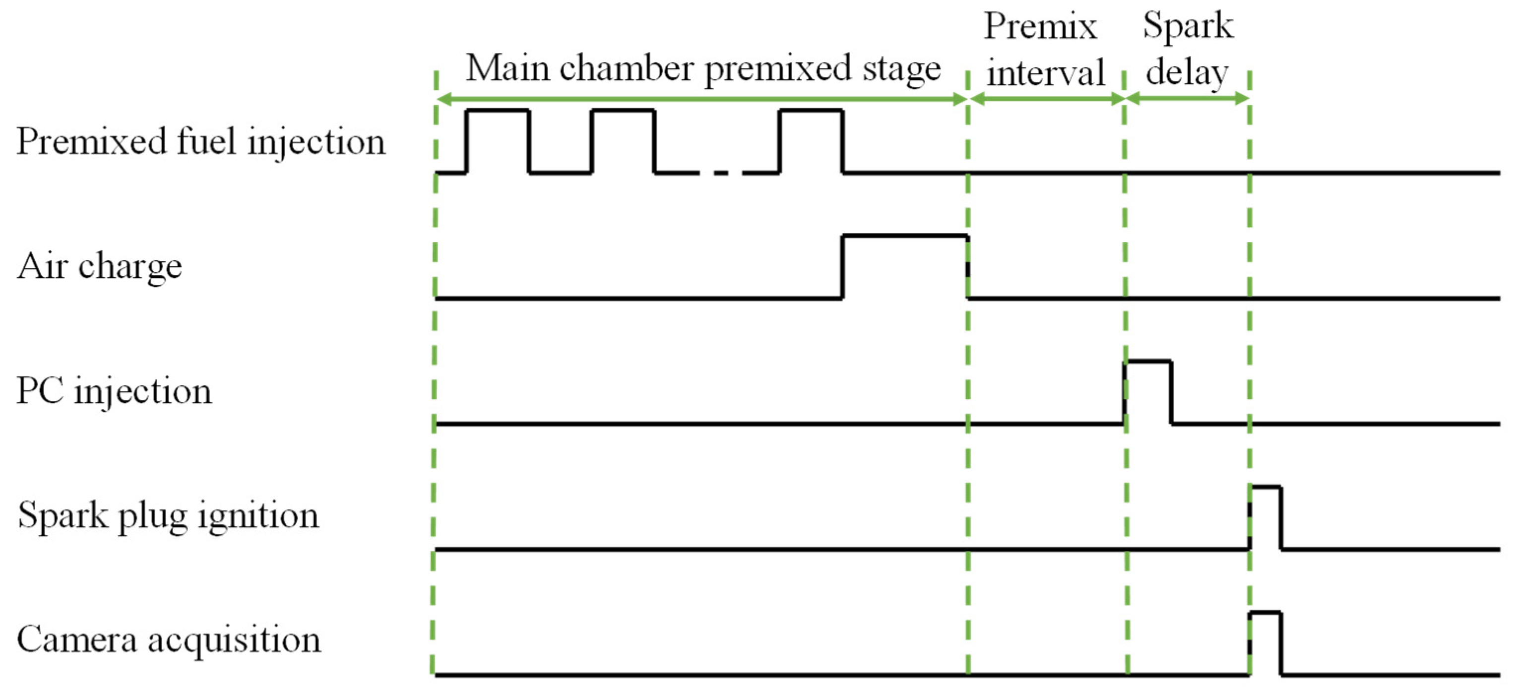
Figure 3 shows the gasoline mixture preparation and signal control during the experiment. To ensure that the gasoline fuel is relatively uniformly mixed in the main chamber of CVCC, the CVCC is heated to 373 K before the experiment. Then, a sufficient amount of fuel is injected in the premixing stage by the MC injector according to the condition. Subsequently, the corresponding mass of air is charged and left for more than 180 s as a premix interval. It is ignited after the premix interval with PPC. When the ignition method is APC, there is an injection process with a PC injector after the premix interval. The spark delay in the PC is set at 1 ms.
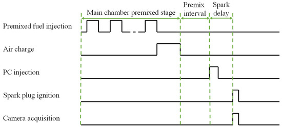
Figure 3.
Gas mixture preparation and ignition control signal.
2.2. Combustion Performance Parameters
Since the total amount of fuel differs at different λ and ambient pressure conditions, the calculated integral heat release is challenging to evaluate intuitively. The heat release rate of CVCC is calculated using the isentropic index algorithm that ignores the heat exchange of the chamber. As shown in Equation (1), the calculated heat release result is lower than the actual heat release.
κ is the polytropic coefficient, P is the pressure, and V is the volume of the CVCC.
The integral heat release (IHR) is the integral of Qi by time, 5% IHR is defined as the ignition delay period, and 5% to 90% IHR is defined as the main combustion period.
The premixing time in the CVCC is long enough. It can be considered that the gasoline fuel in the chamber is premixed homogeneously. The theoretical PC excess air coefficient can be calculated by referring to the method of Shah et al. [16], as shown in Equation (2) below:
where is the volume ratio of the PC and MC, is the premixed fuel mass in the MC, is the low-fuel mass injected into the PC.
According to a large number of research results, the combustion efficiency of lean combustion is generally higher than that of stoichiometric combustion [17]. Therefore, this article uses the heat release change ratio RHR to evaluate the heat release at different premixed λ conditions, calculated according to the proportion of stoichiometric combustion, as shown in Equation (3).
Q is the integral heat release calculated from a specific operating condition, m is the actual fuel injection amount at the working condition, Qsto is the integral heat release at stoichiometric combustion conditions, and msto is the fuel injection mass at stoichiometric combustion conditions.
2.3. Jet Flame Analysis Method
The flame propagation process generally includes jet flames in six different directions in the 6-hole pre-chamber. To evaluate the axial propagation of the jet flame along the jet nozzle direction, the average jet flame penetration length can be calculated using all collected flame jet lengths.
where the refers to the jet length in the axis direction of all orifices in the flame image plane. In addition, according to the flame area change of the jet flame propagation in the optical window, the flame jet area of the equivalent average jet penetration length at any moment can be calculated, as shown in Figure 4.
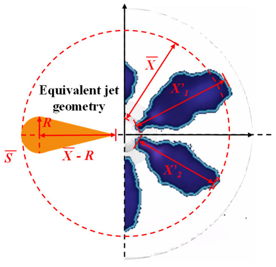
Figure 4.
Jet flame geometry and equivalent jet geometry.
The geometric development of flame jet is similar to the entrainment of spray and fuel-premixed combustion. Its geometric shape can be approximated as a combination of triangle and semicircle [17], as shown in Equation (5).
S is the cumulative flame area obtained by image post-processing, and R is the approximate spherical radius. The equivalent jet flame volume can be obtained by Equation (6).
The volume of the flame jet represents the gas amount of the flame entrainment, and the entrainment ratio Φ can be defined as the percentage change rate of the jet flame volume at different ambient pressure conditions [18] by Equation (7).
where is the jet flame volume of stoichiometric combustion at 0.5 MPa initial ambient pressure.
3. Results and Discussion
3.1. Combustion Pressure and Heat Release Rate
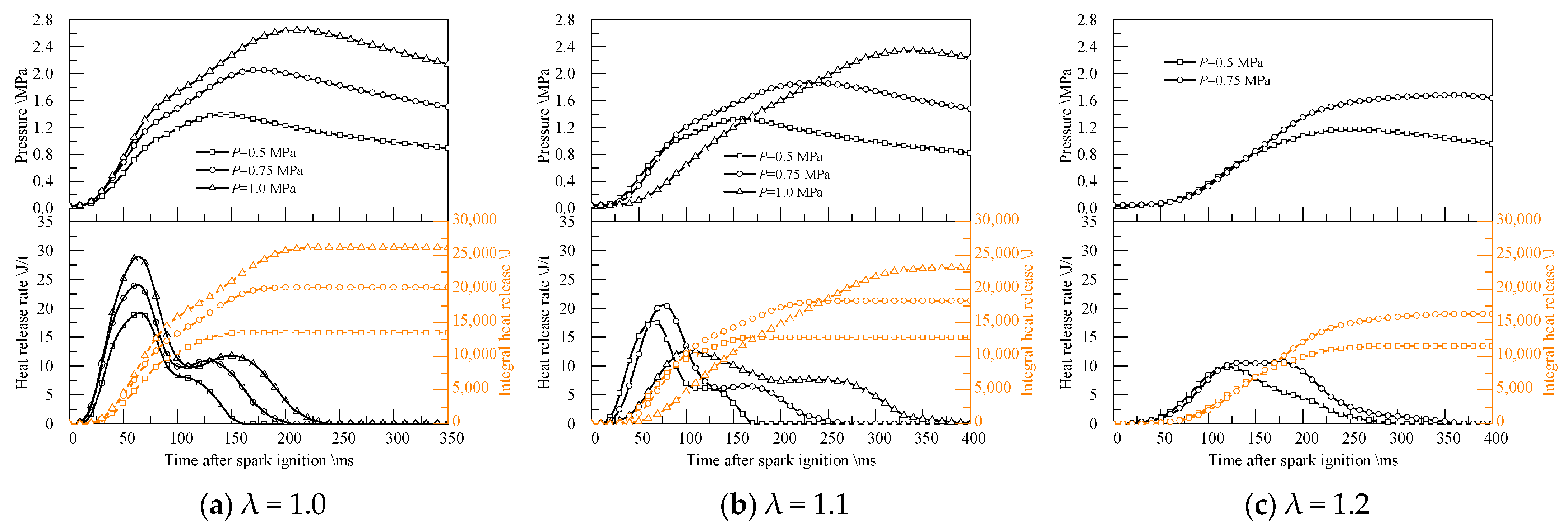
Figure 5 shows the combustion pressure and heat release rate of stoichiometric combustion and lean combustion of PPC at different ambient pressures. Figure 6 shows the combustion characteristics of PPC with different λ at different ambient pressures. The increase in premixed fuel causes the maximum pressure and integral heat release to increase with the increase in initial ambient pressure. It can be found from Figure 5 and Figure 6 that as premixed λ increases at high ambient pressure (1.0 MPa), the combustion performance decreases sharply, and the peak heat release rate decreases rapidly compared with low ambient pressure. The peak heat release rate at 1.0 MPa ambient pressure is reduced to the minimum when λ = 1.1 as the turning point showing. The integral heat release change ratio RHR is only higher than the stoichiometric combustion condition at lean combustion condition with 0.5 MPa ambient pressure. With 0.75 MPa and 1.0 MPa initial ambient pressures, RHR decreases as λ increases. At the same time, lean combustion will reduce the flame propagation speed and slow down the intensity of combustion heat release. The heat release curve gradually becomes flat, and misfire occurs at 1.0 MPa ambient pressure of λ = 1.2.
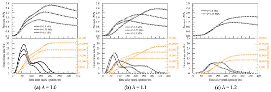
Figure 5.
Combustion pressure and heat release rate of different premixed λ.
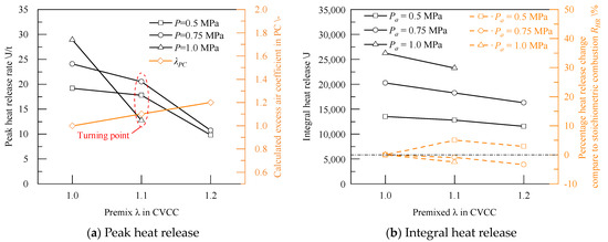
Figure 6.
Peak and integral heat release of PPC.
Figure 7 shows the changes in the ignition delay period and main combustion period of PPC at different premixed λ at different initial ambient pressures. The ignition delay at different initial ambient pressures with stoichiometric combustion is consistent, indicating that the ignition delay is not significantly related to the ambient pressure at the stoichiometric ratio. The initial ambient pressure increase in the pre-chamber makes the ignition delay and main combustion period significantly prolonged, which may be due to the flame propagation speed in the PPC reducing with the increase in premixed λ.
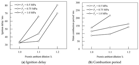
Figure 7.
Combustion period of PPC.
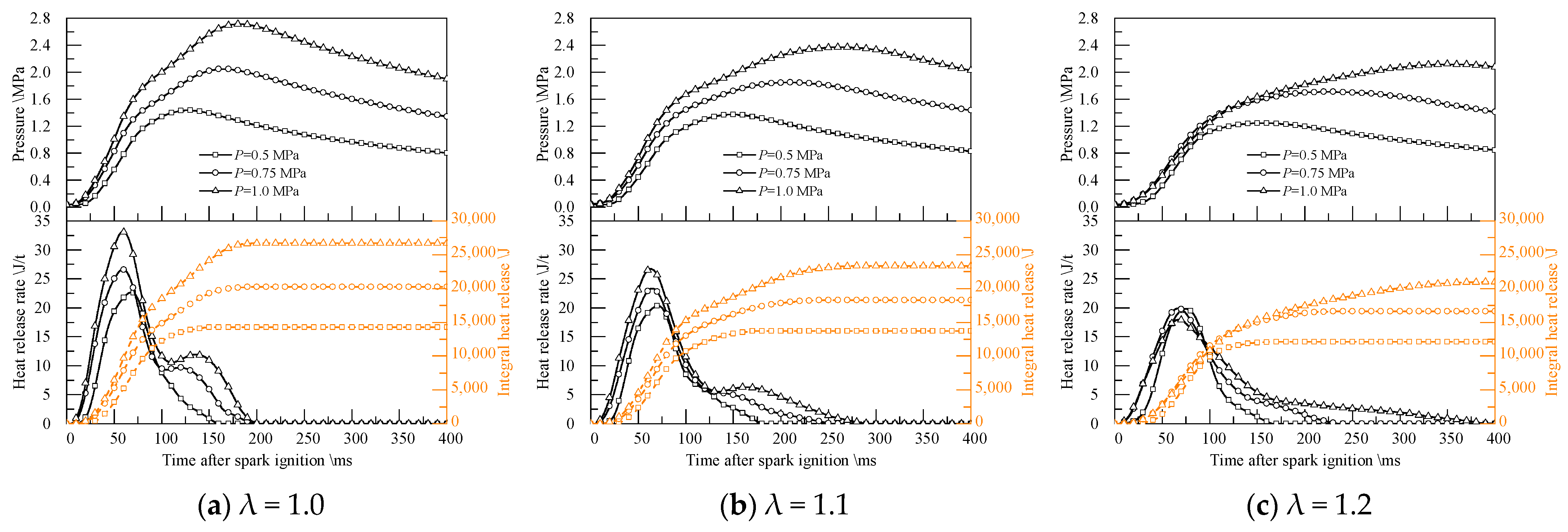
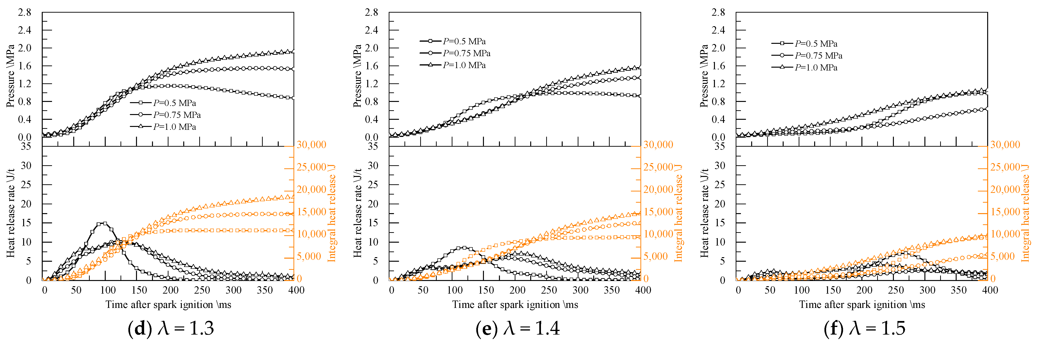
Figure 8 shows the combustion pressure and heat release rate curves of APC. With the additional low-flow injection in the PC to improve the performance of the jet ignition system, the lean combustion limit is expanded from λ = 1.2 to λ = 1.5 compared to those mentioned above in the PPC system. At the stoichiometric conditions of the APC and the slightly lean condition (λ = 1.1), the combustion heat release performance of high ambient pressure is still better than that of low ambient pressure, and the peak heat release rate increases with the increase in ambient pressure, and there is a two-stage heat release period. Starting from λ = 1.2, the negative impact of the initial ambient pressure in CVCC on jet ignition and flame propagation performance, the peak heat release decreases and the timing of peak heat release delays with the increase in λ. At the same time, the heat release only has one period when λ is over 1.2.
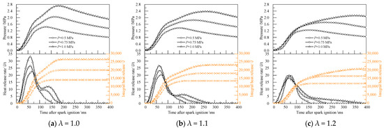
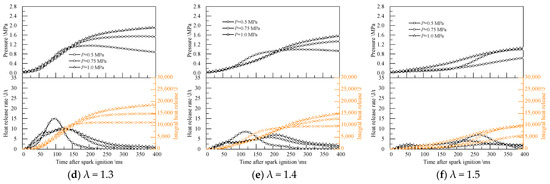
Figure 8.
Pressure and heat release at different premixed λ.
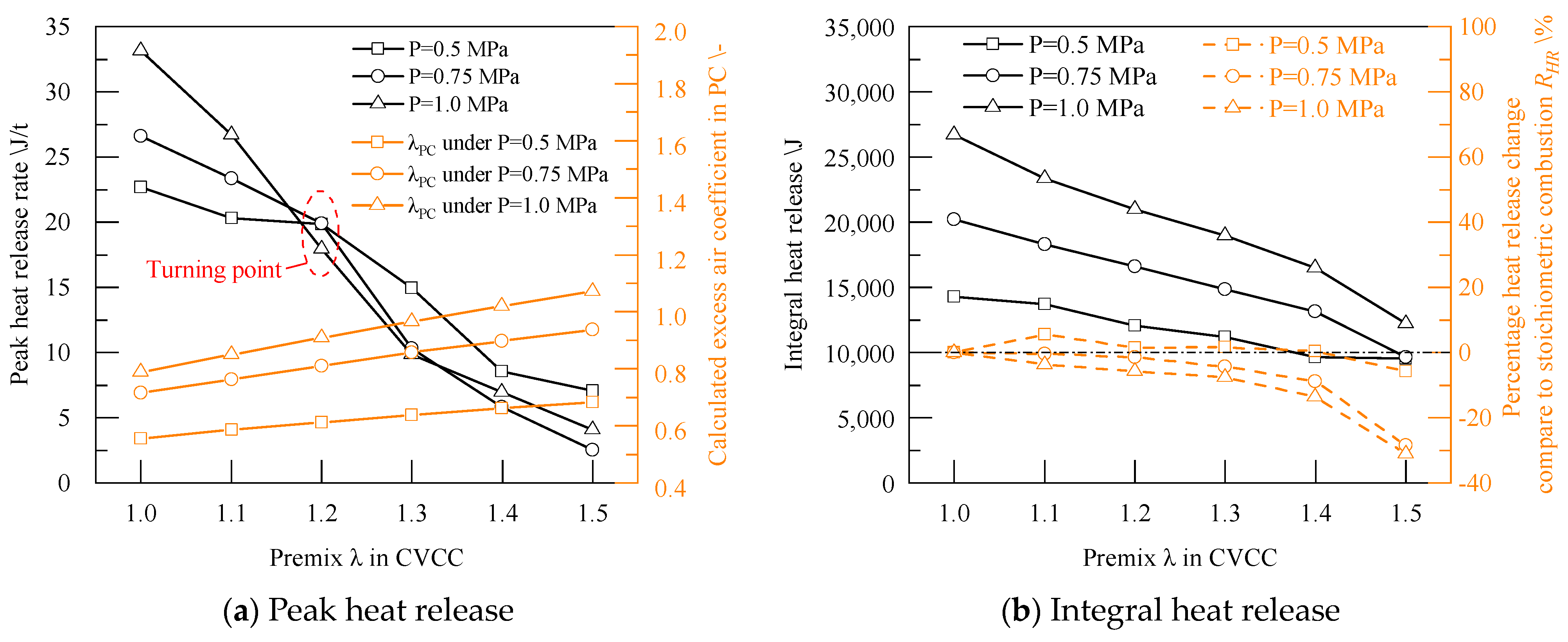
Figure 9 shows the combustion characteristics of APC. Since the low-flow fuel injection maintains the minimum injection duration, the excess air coefficient of PC is closer to the premixed λ as the initial ambient pressure and λ increase. The peak heat release rate at the condition of λ = 1.0 and 1.1 positively correlates with the increased ambient pressure. A turning point occurs when λ = 1.2, and the peak heat release rate at 0.75 and 1.0 MPa decreases rapidly as λ increases. When λ ≥ 1.3, the peak heat release rate is negatively correlated with changes in ambient pressure, and a low ambient pressure of 0.5 MPa shows higher peak heat release performance.

Figure 9.
Peak and integral heat release of APC.
The difference in integral heat release in Figure 9b at different ambient pressure conditions gradually decreases as λ increases, indicating that the combustion heat release efficiency of high ambient pressure decreases faster than that of low ambient pressure. By converting the combustion efficiency with the stoichiometric ratio, the integral heat release percentage change value RHR in Figure 9b can be the same as the PPC. The lean combustion efficiency of low ambient pressure jet ignition is improved in most conditions. The combustion efficiency improves the most when λ = 1.1, reaching 5.6%. When approaching the lean limit, the RHR decreases. Relatively high ambient pressures of 0.75 and 1.0 MPa will cause the lean combustion efficiency to continue to decrease. RHR drops to the minimum value at various ambient pressure conditions when approaching the lean limit λ = 1.5.
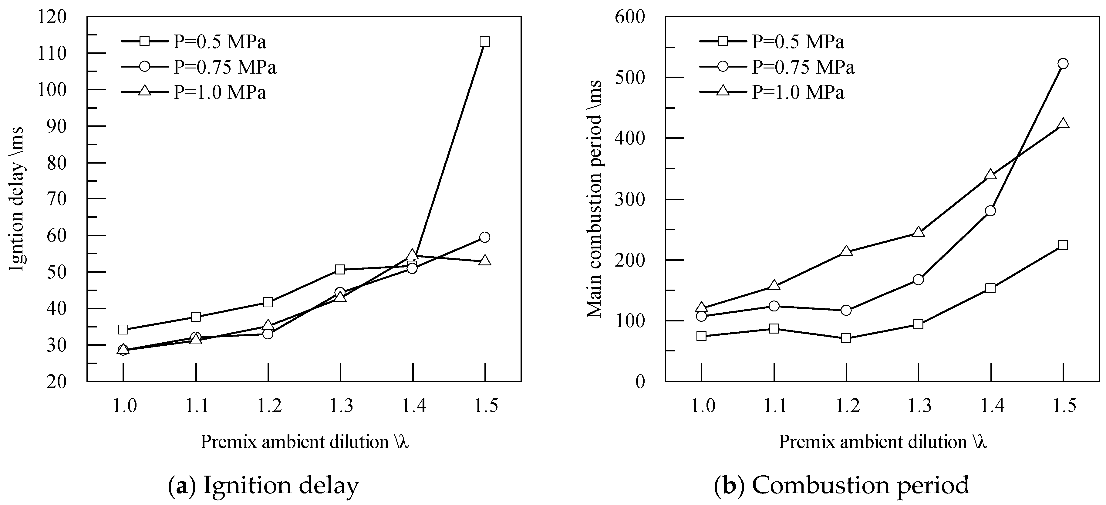
Figure 10 shows the ignition delay period and main combustion period of APC. The ignition delay period increases as λ increases. Ignition delay at high ambient pressure of APC is mostly lower from stoichiometric to lean combustion. This is due to the low energy of the premixed gas at low initial ambient pressure, and low-flow fuel injection enrichment in the PC leads to fuel enrichment, which reduces the flame propagation speed in the PC. At high ambient pressure conditions of 0.75 and 1.0 MPa, the fuel injection amount of 0.64 mg makes the excess air coefficient of PC closer to premixed λ. Hence, the ignition delay is lower than that of lower ambient pressure. Starting from λ = 1.4, lean combustion mainly affects ignition delay. Due to the significant reduction in heat release rate, the influence of ambient pressure on ignition delay no longer plays a dominant role. The ignition delay at lean conditions can be minimized by controlling the fuel concentration in the PC near the stoichiometric ratio when the combustion heat release is stable.

Figure 10.
Combustion period of APC.
The main combustion period continues to increase as λ increases. At most operating conditions, the main combustion period of high ambient pressure at the same λ is higher than that at low ambient pressure, indicating that the main combustion period mainly depends on the premixed λ of the main chamber. Jet ignition only determines the flame propagation and combustion characteristics in the early stages of combustion.
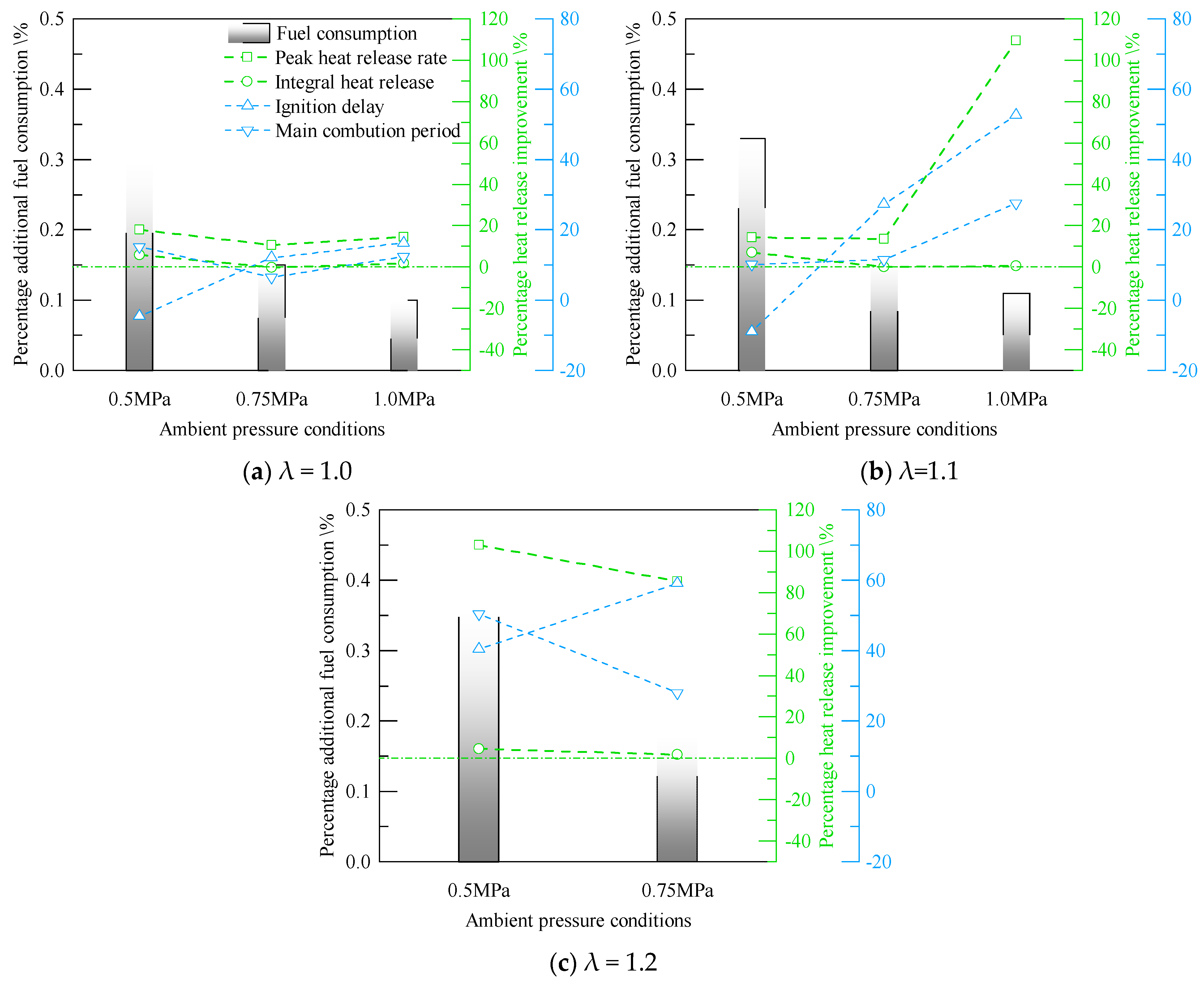
Figure 11 compares the combustion heat release performance of APC to PPC at different ambient pressure conditions. The APC has additional fuel consumption compared with the PPC. With the same low-flow fuel injection duration, the proportion of additional fuel consumption decreases as the ambient pressure increases, while it rises as λ increases. APC has achieved more significant performance gains than PPC in most combustion by adding a small proportion of 0.1% to 0.4% of additional fuel in the CVCC.

Figure 11.
Improvement comparison to PPC.
There are gains in peak heat release rate and integral heat release at various ambient pressure conditions. The peak heat release rate and integral heat release change simultaneously, and the heat release values of APC are higher than those of PPC. Combustion efficiency has the most significant improvement at low ambient pressure. When premixed λ is 1.1, the heat release performance of the PPC drops sharply due to the increase in ambient pressure. The APC has a more significant increase in heat release rate than the PPC.
Since the calculated theoretical λPC at the ignition time of APC belongs to the rich combustion range, the ignition delay period is generally longer than that of PPC. The ignition delay of the APC at low ambient pressure is higher than that of the PPC. Increasing the ambient pressure can shorten the ignition delay period. However, compared with the PPC, APC significantly shortens the main combustion period at lean combustion.
At stoichiometric combustion conditions, the main combustion periods of the two jet ignition methods at various ambient pressures are not much different. As λ increases, the combustion performance of the APC begins to improve, and the main combustion period is significantly shortened. Compared with PPC, APC has a faster heat release rate and more stable combustion performance at the same premixed λ.
3.2. Jet Flame Image Analysis
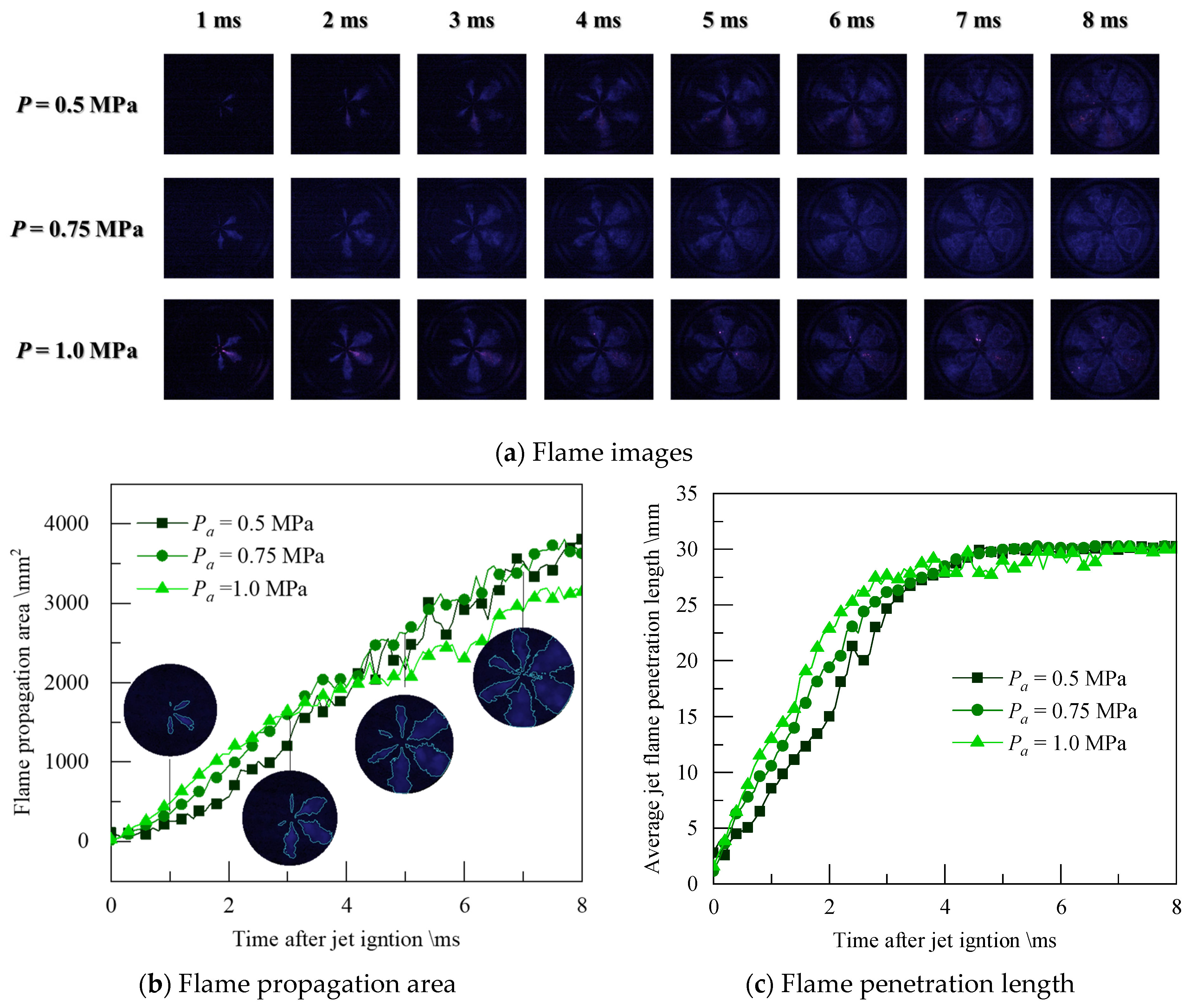
Figure 12 shows the flame images and flame analysis parameters of the PPC at stoichiometric combustion. The analysis starts with ignition timing. The jet flame area represents the flame propagation in the plane, while the jet length better represents the flame propagation in the jet direction.

Figure 12.
Flame images and analysis at stoichiometric combustion of PPC.
The changes in flame propagation area at three different initial ambient pressure conditions are relatively close. At the condition of 1.0 MPa, the jet flame area increases rapidly in the initial stage, mainly related to the proper mixture state in the PC. The jet mixture concentration closer to the stoichiometric ratio brings a high-intensity jet flame, as shown in Figure 12c. The average penetration length of the jet is longer at the same time as the ambient pressure increases, indicating that the jet flame propagation velocity at high ambient pressure is faster in the initial stage of the jet ignition.
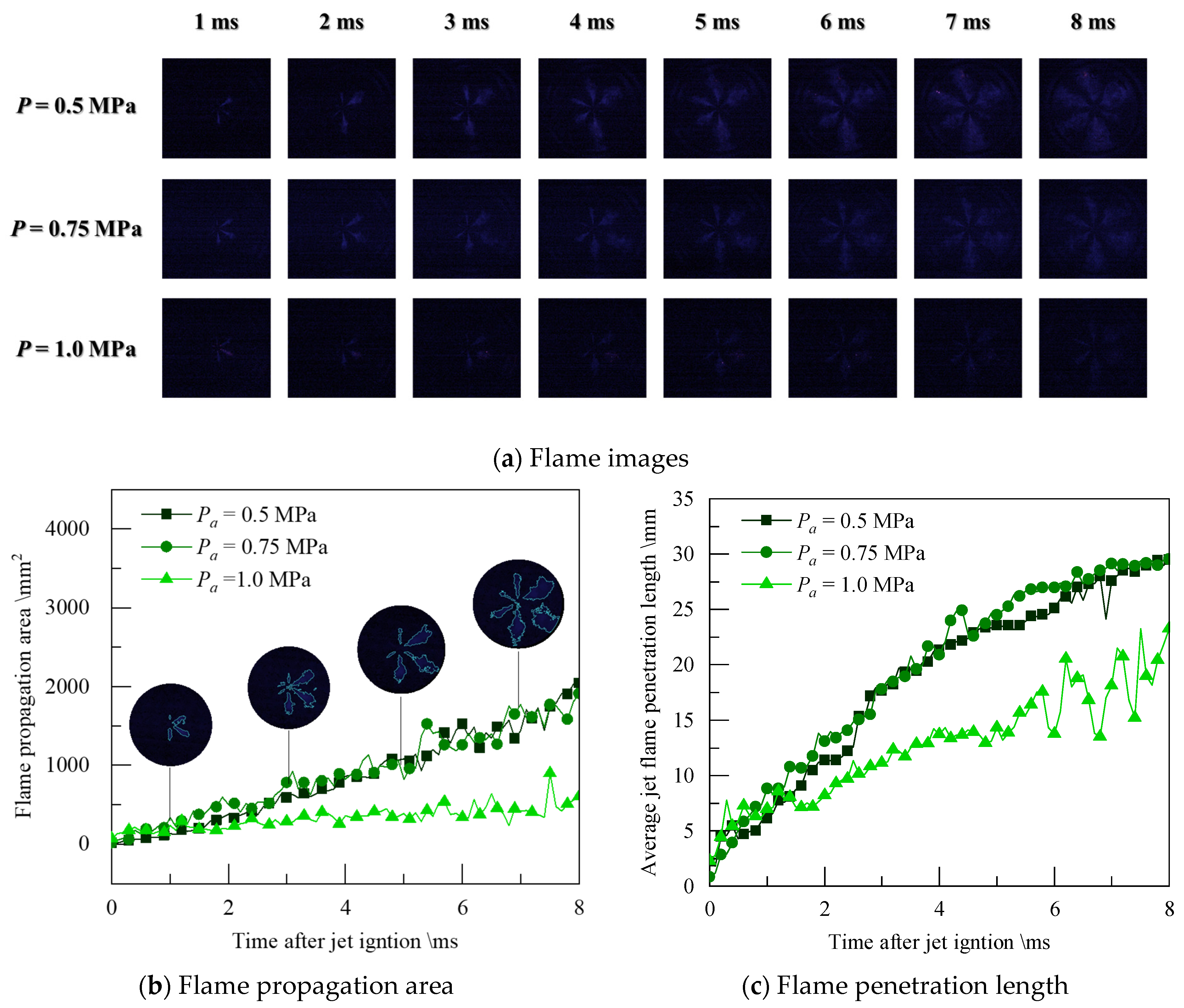
At the condition of λ = 1.1, the combustion intensity decreases, causing low-temperature combustion to dominate, and the brightness of the captured flame image is significantly weakened, as shown in Figure 13. The jet penetration length and flame area of 0.75 MPa ambient pressure is considerably higher than that of 0.5 MPa ambient pressure, which is consistent with the trend of heat release peak. The peak heat release rate at the maximum ambient pressure of 1.0 MPa is significantly lower than that during stoichiometric combustion, and the combustion state is already close to the lean limit at this ambient pressure condition. The λ significantly impacts the flame propagation intensity in the jet direction at high ambient pressure conditions and the turbulent diffusion entrainment propagation intensity of the in-plane jet flame. At the condition of λ = 1.1, the PPC can no longer achieve good jet ignition and turbulent diffusion combustion performance at 1.0 MPa.

Figure 13.
Flame images and analysis at lean combustion (λ = 1.1) of PPC.
Figure 14 shows the calculated jet volume and jet flame entrainment change Φ of the PPC at different times. Stoichiometric combustion always maintains a larger jet flame volume than lean combustion, and the entrainment volume increases with the increase in the ambient pressure in the constant volume chamber. The higher the entrainment change Φ, the better the jet flame propagation and combustion heat release performance. When λ = 1.1, due to the sharp decrease in the jet penetration length and flame propagation area at high ambient pressure conditions, the jet entrainment is also at the lowest level, resulting in the jet ignition at 1.0 MPa condition being close to the lean combustion limit.

Figure 14.
Calculated jet volume and jet flame entrainment change.
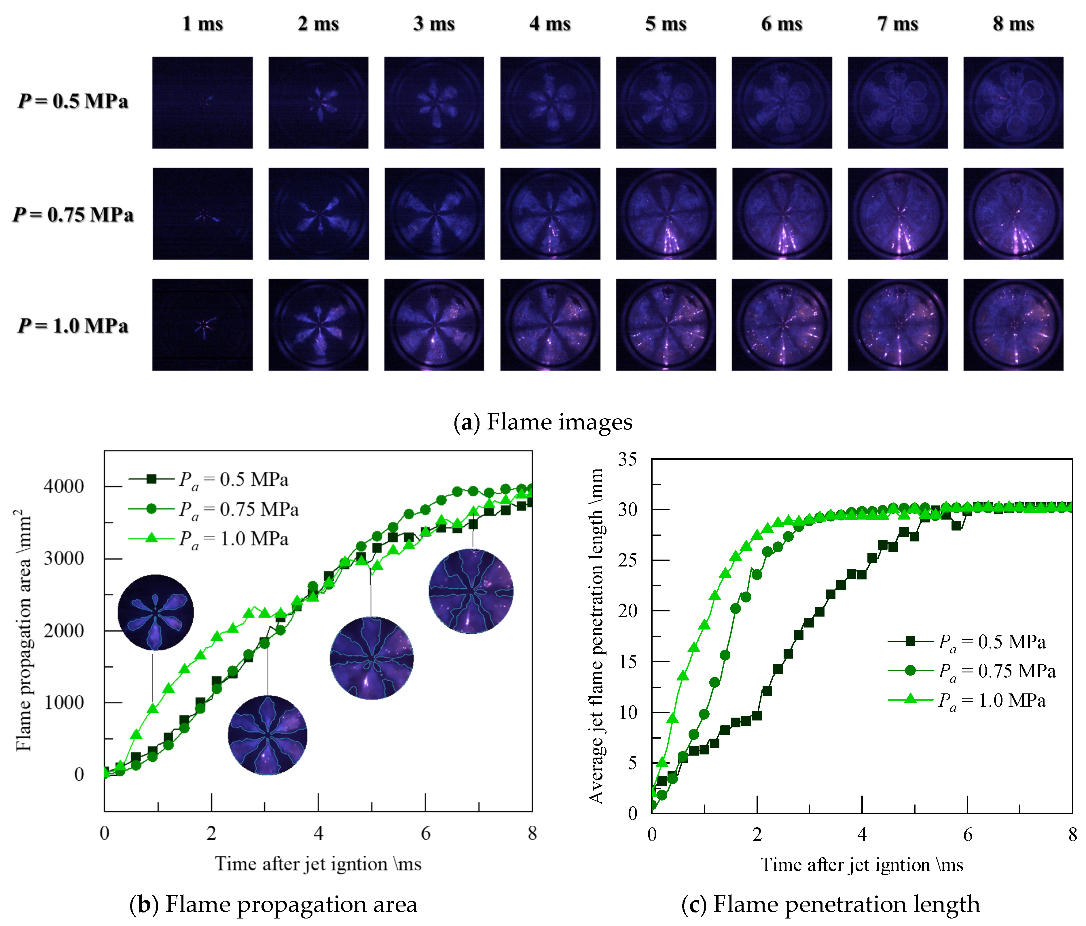
Figure 15 shows the flame propagation images, flame area, and jet penetration of APC stoichiometric combustion. Through the additional low-flow fuel injection in the pre-chamber, the image’s overall brightness in the jet phase is significantly increased compared to that of PPC. Although the pre-chamber is in a fuel-enriched state, the energy intensity of the jet still increases significantly.
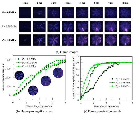
Figure 15.
Flame images and analysis at stoichiometric combustion of APC.
Similar to the changes in the PPC, at stoichiometric combustion conditions, the jet area with a high ambient pressure of 1.0 MPa has the highest growth rate in the early stage, and the difference in area change is mainly concentrated in the jet propagation stage. After the jet flame front reaches the optical limit of the window, the difference in area change gradually decreases, especially because the jet flame of high ambient pressure condition has the highest velocity, and the flame propagates quickly in the direction of the jet.
Figure 16 below shows the flame image area and jet penetration of the APC at λ = 1.2. The peak heat release rate trend is consistent with the jet penetration velocity trend at different ambient pressures. The main reason for the heat release is the flame jet intensity, and the jet penetration is a direct reflection of the jet flame intensity.
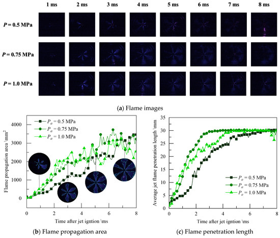
Figure 16.
Flame images and analysis at lean combustion (λ = 1.2) of APC.
Compared with stoichiometric combustion in APC, the difference in jet penetration between different ambient pressure conditions decreases, and the difference in area change increases. It shows that the difference in flame propagation area is mainly in the circumferential direction and is closely related to the jet flame shape during the jet development process. At the condition of λ = 1.2, the peak heat release is the lowest at 1.0 MPa. However, it still maintains a jet penetration length and speed higher than 0.5 MPa, which means that additional fuel injection in the active pre-chamber can improve flame propagation in the jet direction even at high ambient pressure.
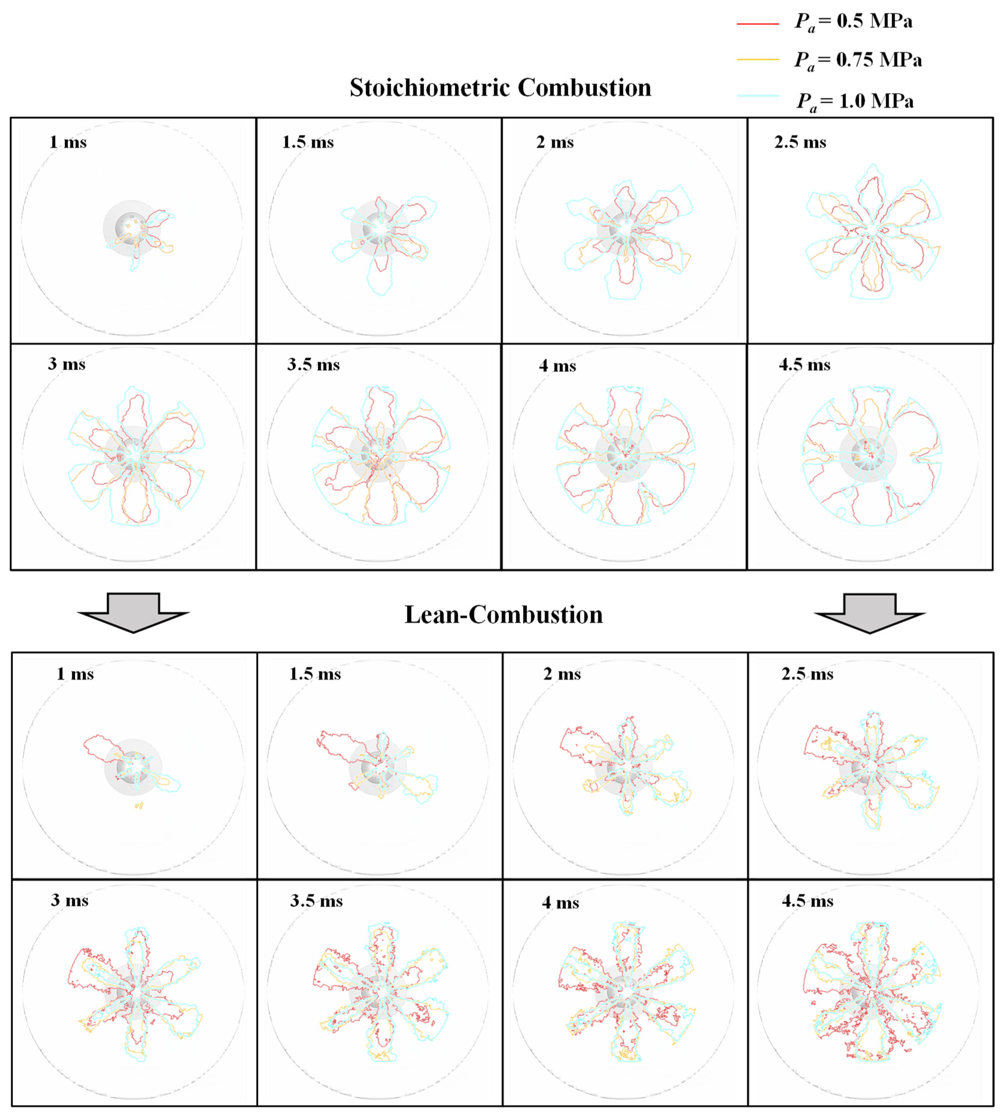
Figure 17 shows the evolution of the flame profile at different ambient pressures at λ = 1.2. At high ambient pressure of 1.0 MPa, combustion heat release performance decreases, jet velocity decreases, and uniformity worsens. Due to the weak entrainment ability of the flame area, the circumferential propagation speed slows down. Although the jet entrainment volume is directly related to the jet velocity, the effect of high ambient pressure dominates. The result of ambient pressure on jet flame propagation is mainly reflected in transforming a wide jet flame into a narrow jet flame, thereby prolonging the in-plane flame propagation time. It can also be seen from the figure that the jet flame is asymmetrical because the spark plug in the pre-chamber is not installed in the central position, so the distance between the electrode gap and the outlet of the pre-chamber is different, thus showing the non-uniformity of the jet flame.
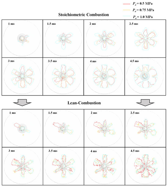
Figure 17.
Jet flame contour of different ambient pressure.
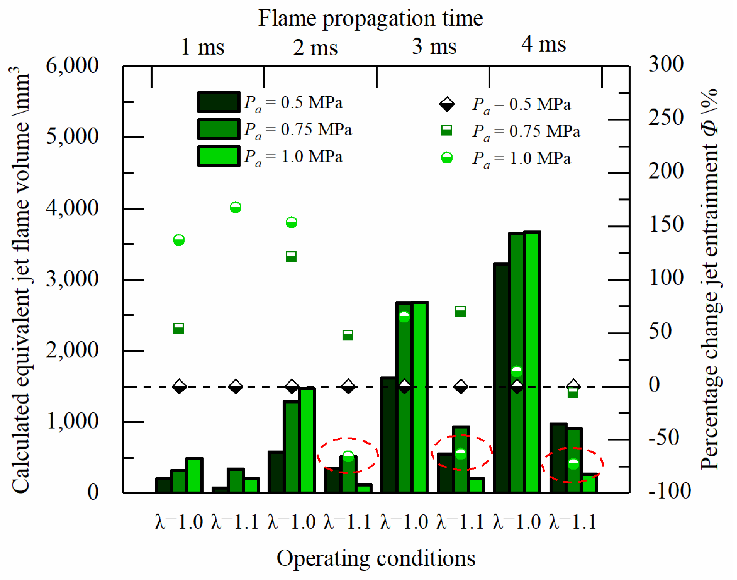
Figure 18 shows the jet volume and entrainment change Φ calculated at different times. At the combustion condition of stoichiometric ratio λ = 1.0, the jet flame volume increases significantly as the ambient pressure increases, and the change rate of entrainment volume at high ambient pressure relative to the low ambient pressure of 0.5 MPa is positive. At lean combustion conditions, the initial jet flame entrainment volume at high ambient pressure increases the jet intensity due to the additional low-flow fuel injection, and the entrainment volume change rate is higher than that at 0.5 MPa low ambient pressure. With the jet flame’s development, the jet flame’s volume at the condition of 1.0 MPa at 3 ms and 4 ms after jet flame ignition in CVCC has been less than that of 0.5 MPa. The change rate of the entrainment amount has become negative simultaneously.

Figure 18.
Equivalent jet volume and percentage entrainment change of different ambient pressures.
4. Conclusions
This paper studied the effect of initial ambient pressure on APC and PPC with a constant volume combustion chamber. The heat release rate, IHR, heat release change ratio, flame area, jet flame propagation length, and percentage change jet entrainment were used to investigate the combustion and flame propagation characteristics. The main conclusions are as follows:
- The APC could expand the lean limit to premixed λ = 1.5 compared with premixed λ = 1.2 of PPC at different ambient pressures.
- At stoichiometric and slightly lean combustion conditions, appropriately increasing the ambient pressure can promote ignition and combustion performance of APC and PPC with the heat release peak increased and the combustion period shortened. At lean combustion conditions, the ignition and combustion performance decrease rapidly after the premixed λ exceeds a certain value at high ambient pressure, while APC could increase the premixed λ corresponding to this turning point.
- At the stoichiometric combustion and slightly lean combustion (λ = 1.0 and λ = 1.1) conditions with APC, the peak heat release rate positively correlates with the initial ambient pressure increase. As the premixed λ increases, the peak heat release rate and ambient pressure negatively correlate.
- The ignition delay increases with the increase in premixed λ. At the same time, the ignition delay period of APC is directly related to the fuel concentration in the PC. The ignition delay can be minimized by controlling the excess air coefficient in the pre-chamber near the stoichiometric ratio.
- The high initial ambient pressure in the constant volume chamber dramatically reduces the volume of the jet flame and the mixture entrainment capacity at lean combustion conditions, thereby reducing the combustion speed and peak heat release. At the same time, the APC can significantly increase the jet intensity, which could weaken the ambient pressure effect on the jet penetration at lean combustion conditions.
Author Contributions
M.L.: Software, Methodology, Validation, Investigation, Formal analysis, Visualization, Writing—Original Draft, Writing—Review and Editing; Z.H.: Conceptualization, Supervision, Funding acquisition, Writing—Review and Editing; X.M.: Investigation, Writing—Review and Editing; Z.W.: Investigation, Funding acquisition, Writing—Review and Editing; X.W.: Investigation, Funding acquisition, Writing—Review and Editing; W.Y.: Investigation, Writing—Review and Editing; Y.T.: Investigation, Formal analysis, Writing—Original Draft, Writing—Review and Editing; Z.K.: Writing—Review and Editing; J.D.: Conceptualization, Supervision, Funding acquisition, Writing—Review and Editing. All authors have read and agreed to the published version of the manuscript.
Funding
This research was funded by the National Natural Science Foundation of China (No. 52076153), the Shanghai Science and Technology Program (No. 22ZR1463000), the projects in Science and Technique Plans of Ningbo City (No. 2022Z023) and the National Key R&D Program of China (2021YFB2500800).
Data Availability Statement
The original contributions presented in the study are included in the article, further inquiries can be directed to the corresponding author.
Conflicts of Interest
Authors Zhiyu Wang and Xijiang Wu were employed by the SAIC Motor Corporation Limited. The remaining authors declare that the research was conducted in the absence of any commercial or financial relationships that could be construed as a potential conflict of interest.
Abbreviations
| Combustion heat release change ratio | |
| Integral heat release rate | |
| Integral heat release rate at stoichiometric combustion condition | |
| Fuel injection mass | |
| Fuel injection mass at stoichiometric combustion condition | |
| The average jet flame penetration length | |
| X’ | The jet length in the axis direction |
| S | The cumulative flame area |
| R | The approximate spherical radius |
| The equivalent jet flame volume | |
| The jet flame volume of stoichiometric combustion at 0.5 MPa initial ambient pressure | |
| Percentage change rate of the jet flame volume | |
| APC | Active pre-chamber |
| CVCC | Constant volume combustion chamber |
| HEI | High-energy spark ignition |
| MCP | Main chamber combustion period |
| PC | Pre-chamber |
| PPC | Passive pre-chamber |
References
- Toulson, E.; Schock, H.; Attard, W. A Review of Pre-Chamber Initiated Jet Ignition Combustion Systems; SAE Technical Paper 2010-01-2263; SAE International: Warrendale PA, USA, 2010. [Google Scholar] [CrossRef]
- Joshi, A. Review of Vehicle Engine Efficiency and Emissions. SAE Int. J. Adv. Curr. Pract. Mobil. 2020, 2, 2479–2507. [Google Scholar] [CrossRef]
- Atis, C.; Chowdhury, S.; Ayele, Y.; Stuecken, T.; Schock, H.; Voice, A.K. Ultra-Lean and High EGR Operation of Dual Mode, Turbulent Jet Ignition (DM-TJI) Engine with Active Pre-chamber Scavenging; SAE Technical Paper 2020-01-1117; SAE International: Warrendale, PA, USA, 2020. [Google Scholar] [CrossRef]
- Ayala, F.; Gerty, M.; Heywood, J. Effects of Combustion Phasing, Relative Air-fuel Ratio, Compression Ratio, and Load on SI Engine Efficiency; SAE Technical Paper 2006-01-0229; SAE International: Warrendale, PA, USA, 2006. [Google Scholar] [CrossRef]
- Li, F.; Wang, Z.; Wang, Y.; Wang, B. High-Efficiency and Clean Combustion Natural Gas Engines for Vehicles. Automot. Innov. 2019, 2, 284–304. [Google Scholar] [CrossRef]
- Jamrozik, A.; Tutak, W. A study of performance and emissions of SI engine with a two-stage combustion system. Chem. Process Eng. 2011, 32, 453–471. [Google Scholar] [CrossRef]
- Shi, J.; Wang, J.; Deng, J.; Miao, X.; Liu, Y.; Li, L. Study on Combustion and Emission Characteristics of High Compression Ratio Gasoline Engine Based on Two-stage High Energy Ignition and Passive Pre-chamber. Automot. Eng. 2021, 43, 1300–1307. [Google Scholar] [CrossRef]
- Wimmer, D.; Lee, R. An Evaluation of the Performance and Emissions of a CFR Engine Equipped with a Prechamber; SAE Technical Paper 730474; SAE International: Warrendale, PA, USA, 1973. [Google Scholar] [CrossRef]
- Wu, J.; Chen, J.; Du, J.; Chen, H.; Li, Y.; Zhan, W. Combustion and Emission Characteristics of a Lean Burn Gasoline Direct Injection Engine with Active Pre-chamber. Chin. Intern. Combust. Engine Eng. 2021, 42, 55–60. [Google Scholar]
- Attard, W.P.; Fraser, N.; Parsons, P.; Toulson, E. A Turbulent Jet Ignition Pre-Chamber Combustion System for Large Fuel Economy Improvements in a Modern Vehicle Powertrain. SAE Int. J. Engines 2010, 3, 20–37. [Google Scholar] [CrossRef]
- Zheng, Z.; Wang, L.; Pan, J.; Pan, M.; Wei, H. Numerical Investigations on Turbulent Jet Ignition with Gasoline as an Auxiliary Fuel in Rapid Compression Machines. Combust. Sci. Technol. 2023, 195, 672–691. [Google Scholar] [CrossRef]
- Yang, X.; Cheng, Y.; Zhao, Q.; Wang, P.; Chen, J. Effect of spark ignition location on the turbulent jet ignition characteristics in a lean burning natural gas engine. Int. J. Engine Res. 2023, 24, 702–719. [Google Scholar] [CrossRef]
- Wang, Q.; Hu, L.; Chung, S.H. Blow-out of nonpremixed turbulent jet flames at sub-atmospheric pressures. Combust. Flame 2017, 176, 358–360. [Google Scholar] [CrossRef]
- Kim, H.J.; Van, K.; Lee, D.K.; Yoo, C.S.; Park, J.; Chung, S.H. Laminar flame speed, Markstein length, and cellular instability for spherically propagating methane/ethylene–air premixed flames. Combust. Flame 2020, 214, 464–474. [Google Scholar] [CrossRef]
- Zhang, C. 3-D CFD Simulation of the Working Process of a Marine Gas Engine. Master’s Thesis, Dalian University of Technology, Dalian, China, 2013. [Google Scholar]
- Shah, A.; Tunestal, P.; Johansson, B. Effect of Relative Mixture Strength on Performance of Divided Chamber ‘Avalanche Activated Combustion’ Ignition Technique in a Heavy Duty Natural Gas Engine; SAE Technical Paper 2014-01-1327; SAE International: Warrendale, PA, USA, 2014. [Google Scholar] [CrossRef]
- Busch, S.; Bohac, S.V.; Assanis, D.N. A Study of the Transition Between Lean Conventional Diesel Combustion and Lean, Premixed, Low-Temperature Diesel Combustion. J. Eng. Gas Turbines Power 2008, 130, 052804. [Google Scholar] [CrossRef]
- Deng, J.; Zhong, H.; Gong, Y.; Gong, X.; Li, L. Studies on injection and mixing characteristics of high pressure hydrogen and oxygen jet in argon atmosphere. Fuel 2018, 226, 454–461. [Google Scholar] [CrossRef]


Disclaimer/Publisher’s Note: The statements, opinions and data contained in all publications are solely those of the individual author(s) and contributor(s) and not of MDPI and/or the editor(s). MDPI and/or the editor(s) disclaim responsibility for any injury to people or property resulting from any ideas, methods, instructions or products referred to in the content. |
© 2024 by the authors. Licensee MDPI, Basel, Switzerland. This article is an open access article distributed under the terms and conditions of the Creative Commons Attribution (CC BY) license (https://creativecommons.org/licenses/by/4.0/).