Abstract
In this paper, a tunable multi-split transmitting (TX) coil for a wireless power transfer (WPT) system that accommodates a wide range of distances between the TX and receiving (RX) coils is proposed. This method enables the WPT system to maintain a stable and consistent output power supply to the load, regardless of variations in coupling coefficients caused by changes in the distance between the TX and RX coils. The tunable multi-split TX coil can operate in various modes depending on how the wire connections between each TX coil are configured. This approach adjusts the inductance value of the TX coil for different conditions, using the same amount of coil as a conventional single-loop TX coil. The results show that by adjusting the TX coil to three different modes as the airgap varies from 50 mm to 250 mm, consistent output power is achieved with smaller variations in the input current and voltage compared to those in a conventional system. A conventional system requires an input voltage increase of approximately 529.64%, while the proposed system requires only a 42.93% increase. The proposed system enhances the power transfer capacity of the WPT system, particularly when operating in an over-coupling state. This approach provides a stable output power supply with a standardized and simplified TX coil structure.
1. Introduction
The demand for wireless power transfer (WPT) capabilities has grown consistently, as such technology enhances the quality of human life by offering inherent advantages over traditional wired power transfer systems in terms of safety and convenience. WPT systems eliminate the risks of electrical hazards such as shocks and short circuits due to their non-contact characteristic. Furthermore, these systems allow for the unrestricted use of power in diverse environments, including underwater, underground, or in snowy conditions [1,2,3]. As WPT technology advances, it will support larger-scale power transmissions, broadening its applicability across various sectors. Today, WPT technology is employed in several fields, including electric vehicles (EVs), portable devices, biomedical equipment, and medium-power applications such as automatic guided vehicles (AGVs) and drones [4,5,6].
A WPT system that utilizes a coupled magnetic field to transfer energy is termed an inductive power transfer (IPT) system. IPT systems operate based on the principle of electromagnetic induction, as also used in transformers. Figure 1 illustrates a typical IPT system. It includes an AC power supply, a power factor correction and rectifier to convert AC-to-DC power, an inverter, a coupling system (transmitting and receiving coils) with compensation networks, a DC-to-DC converter, and the load [7,8].
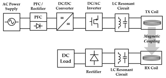
Figure 1.
A typical IPT system, including an AC power supply, a power factor correction, a rectifier, an inverter, compensation circuits, a DC/DC converter, and the load.
Research on wireless charging using inductive coupling has been actively conducted in relation to a range of areas, such as medical equipment, home appliances, electronic devices, and the mobility industry [9,10,11]. Most WPT applications in the mobility sector unify the transmitter coil design to reduce costs. The receiving coil size can also be somewhat standardized based on the size and specifications of the mobility devices.
The coupling coefficient between the TX and RX coil is a critical parameter in an IPT system. It is determined by the relative position, size, shape, and spacing between the TX and RX coils [12,13]. The coupling coefficient between the TX and RX coil should be considered for system optimization, as it determines the power transfer efficiency (PTE), power transfer capacity (PTC), and reliability of the system [14,15]. PTE refers to the ratio of the power received by the load to the power transmitted by the source in a WPT system. PTC refers to the maximum amount of power that can be transferred from the transmitter to the receiver in a WPT system, without exceeding the operational limits of the system [1,7].
The coupling coefficient between the TX and RX coil changes with variations in the airgap. For example, when charging EVs, the height of every vehicle differs, leading to variations in the distance between the vehicle assembly (VA) and the ground assembly (GA) [16]. Varying coupling coefficients significantly affect the PTC and PTE of the system as well as the stability. This makes it difficult to construct a simple and cost-effective WPT system, as the system specifications must be adjusted depending on the different airgaps. A standardized and simplified system design that accommodates different airgaps is essential.
To enhance the PTE and stability of the IPT system, it is crucial to address the impact of varying airgaps between the TX and RX coils. Previous research on efficient power transfers can be categorized into two main approaches [17,18,19,20,21]. The first approach involves adding extra coils on either the TX or RX side or altering the coil design to mitigate the effects of airgaps over a certain range [17,18]. The second method uses impedance matching networks to optimize the system for varying airgaps [19,20,21].
In one study [17], multi-loop and digital capacitors were employed to achieve automatic range-adaptation of magnetic resonant WPT over a wide range of distances. This approach requires additional components, including a microcontroller unit, digital capacitors, and Bluetooth modules, in both the TX and RX units. In another study [19], a tunable matching network and a searching algorithm were proposed to maintain high efficiency across various distances. These two previous works offer solutions for maintaining efficiency and adapting to varying distances in a WPT system.
However, earlier WPT systems [17,19] have notable drawbacks. One significant disadvantage of these approaches is the need for a large surface area. The available space, particularly in the RX unit, is often limited, making it challenging to accommodate the additional components and circuitry. The need for extra coils and digital capacitors further exacerbates this issue, leading to a proportional increase in the overall system size.
Moreover, the inclusion of extra circuits and components results in higher system costs, greater complexity, and more weight. The increased complexity also poses challenges for system integration and maintenance, potentially reducing the overall reliability and lifespan of the WPT system. Additionally, the increased weight due to the added components can be problematic, particularly in applications where weight is a critical factor, such as in mobile or portable devices.
Efficiently supplying stable power using existing resources can lead to more cost-effective and less complex WPT systems. In this paper, a tunable multi-split TX coil is proposed to maintain stable efficiency and consistent output power to the load regardless of variations in the coupling coefficients caused by changes in the distance between the TX and RX coils. The wiring configuration of the multi-split TX coil is controlled using switching elements. This approach simply adjusts the inductance value of TX coil to ensure the stable transfer of power. Compared to a conventional single TX coil, the proposed coil system utilizes the same amount of coil but can transfer power reliably under distance-independent conditions. Implementing this WPT system into the mobility industry can potentially reduce costs, simplify systems, and minimize size, especially in the RX unit, which often faces more significant spatial limitations. Various methodologies for stable output power delivery in WPT systems with varying airgaps are compared in Table 1, highlighting the advantages and disadvantages of the proposed system [19,20].

Table 1.
Comparison of various WPT systems with variable airgaps.
This paper is arranged as follows. In Section 2, the configuration and analysis of the proposed system are described. The proposed idea is verified through 3D EM and circuit simulations in Section 3. The validation through experiments is described in Section 4. Finally, a discussion is given, followed by the conclusion of the paper.
2. Tunable Multi-Split TX Coil
This section examines the impact of variations in the coupling coefficient on the efficiency and output power of a WPT system, along with the underlying reasons for these changes. It also details the strategies employed by the proposed system to ensure that the power transfer remains consistent despite fluctuations in the coupling coefficient, and it outlines the design methods for the compensation circuit.
2.1. Efficiency and Output Power Variation Depending on the Coupling Coefficient
The coupling coefficient between the TX and RX coil () varies depending on changes in the airgap or a misalignment of the TX and RX coils, as mentioned above. Figure 2 shows the PTE and output power variation depending on changes in . Critical coupling () is the condition under which to transfer maximum power [11]. The coupling coefficient is defined as being in an over-coupled condition if it is greater than and in an under-coupled condition if it is smaller than this value [22]. Operating an IPT system in an over-coupling condition leads to a higher PTE than that in a critical coupling condition, but the PTC gradually decreases. On the other hand, in an under-coupling condition shows low PTE and PTC values compared to the critical coupling point.
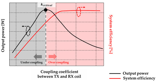
Figure 2.
The variation of the output power and system efficiency depending on the change of when the input voltage is fixed.
The cause of the variations in PTE and PTC depending on the under-coupling, critical, and over-coupling states is the frequency splitting phenomenon. When is higher than , the frequency splitting phenomenon occurs and the single resonant peak of the load power on the receiver side splits into a double peak [23,24,25]. When a WPT system operates in the under-coupling state, meaning the frequency splitting phenomenon does not occur, the magnitude of the impedance at the resonant frequency should be at the minimum value. However, if increases and the frequency phenomenon occurs, there are two points at which the impedance is minimized. Each split resonance frequency has a different optimized energy transfer point. This causes an impedance mismatch, leading to a decrease in the PTC at the natural resonant frequency.
Although the reactance of a WPT system is eliminated by tuning the capacitance, the increased mutual inductance due to the increased creates additional inductive reactance, decreasing the PTC due to the rise in the reactive power [26].
However, the PTE reaches its maximum value at the original resonant frequency regardless of the frequency splitting phenomenon [25]. When increases and the frequency splitting phenomenon occurs, the PTE increases and then becomes saturated. This occurs because the mutual inductance between the TX and RX coil () increases, resulting in an increase in the quality factor [27]. In summary, the maximum transfer power and efficiency cannot be obtained simultaneously when the frequency splitting phenomenon occurs.
In order to achieve a specific output power for the operation of the load, an increase in necessitates a higher input voltage, meaning a decrease in the PTC. Conversely, when decreases due to an increase in the airgap between the TX and RX coils, a higher input current is needed, leading to the decrease in the PTE due to the loss of the conductor.
can be determined by the quality factors of the TX and RX coils. The quality factor can be calculated as follows [27]:
The quality factor of the TX and RX coil can be calculated using Equations (1) and (2), where the operating frequency is represented by , the load resistance is , the resistance values for the TX and RX coil are correspondingly and , and the effective-inductances of the TX and RX coils are likewise and . The quality factor represents a critical parameter that indicates the energy loss characteristics in the coils or the resonant circuit. It also determines the PTE and the bandwidth of the system, making it an essential consideration when constructing a WPT system. The values of and are determined by both the self-inductance and mutual inductance of the TX and RX coils. Self-inductance depends on the physical characteristics of the coil, such as the number of turns, the radius, and the thickness of the Litz-wire used. Mutual inductance can be calculated using the coupling coefficient and the effective inductance. Especially when utilizing multiple TX coils in a WPT system, it is crucial to consider the mutual inductance values between each TX coil to calculate the effective inductance. This in turn enhances the precision in determining the critical coupling point. According to Equation (3), is influenced mainly by , , and the effective inductances of the TX and RX coils.
2.2. Proposed Multi-Split TX Coil System
Figure 3 shows the proposed tunable multi-split TX coil system. For simplicity, the number of TX loops is set to four. In the proposed system, a conventional single-loop TX coil with four turns is split into four loops. Each individual TX coil can be connected both in series or parallel through the switching circuit of the proposed system [28,29]. The inductance value of each TX coil loop varies depending on how the connections between each of the TX coils are configured. If adjacent TX coils, for example, are connected in a series, there are twice as many TX turns. Because the inductance value is proportional to the square of the number of turns, the inductance value of the TX coil () in this case, increases by a factor of four [30].
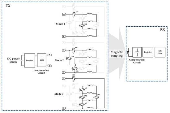
Figure 3.
The three operating modes of the proposed multi-split TX coil system using switching components, composed of a coupling system (TX and RX coil), a power source, an inverter, a compensation circuit for the TX and RX coils, a rectifier, and a DC load. The A and B nodes at the back of the inverter are connected to the respective A and B nodes of each mode.
Each of the four split TX coil loops is designed with coils of an equal length, resulting in identical self-inductance. When TX coils are connected in a series, the number of turns increases by a factor of , making the self-inductance times greater. In contrast, if TX coils are connected in parallel, the total inductance of the TX loops becomes .
The controllable switching circuit in the proposed system can adjust the series and parallel connections of the four-loop TX coils, operating the system in three different modes based on . Here, it is assumed that the inductance of each of the four loop TX coils is The three operating modes of the proposed system are described in Figure 3. Each mode results in a different level of TX inductance, allowing the system to adapt to varying coupling conditions.
- Mode 1: When operating in mode 1, two switches, M2 and M7, are turned on. All four TX loops are connected in a series, forming a single loop with four turns. The total inductance of the TX coil becomes 42 · LTX, as the number of turns is quadrupled.
- Mode 2: When operating in mode 2, three switches, M4, M5, and M7, are turned on. Two of the four loops are connected in a series, and these two series-connected loops are then connected in parallel, resulting in two TX loops with two turns each in parallel. The inductance of each pair is 22 · LTX
- Mode 3: When operating in mode 3, five switches, M1, M2, M3, M6, and M8, are turned on. All four loops are connected in parallel, with each loop maintaining the inductance of LTX.
The induced voltages from the TX coil to the RX coil in a conventional system and the proposed system are expressed here as Equations (4) and (5), respectively. We assume that the total input currents of the conventional and proposed system ( are identical and that each split TX loop has the same input current, . The following equations explain how the proposed system maintains constant output power under varying values without controlling the input current.
The coupling coefficients, with identical output power levels, of the conventional system and the proposed system with a constant input current, are defined as and , respectively. Note that and are the induced voltages at the RX coil in the conventional and proposed system, respectively. is the number of TX loops, is the output power, is the output current, and is the impedance value of the RX coil.
In the conventional system, for consistent output power for the load, and the inductance value of the TX coil () can be controlled according to Equation (4). Using a buck–boost converter or changing the coil design to control and maintain constant output power in a conventional single-coil WPT system will increase the system’s complexity, cost, and size. However, the proposed multi-split TX coil system controls with a switching circuit to maintain the induced voltage, simplifying the system design.
In the proposed system, the values for modes 2 and 3 are times and times that of mode 1, respectively. Therefore, when increases by a factor of 2, operating the system in mode 2 will keep constant according to Equations (5) and (6). Similarly, when increases by a factor of 4, operating the system in mode 3 will maintain a constant .
An adjustment of in the proposed system ensures constant output power according to Equation (7), with the same input current and voltage level in specific airgaps, even in the over-coupling state where PTC decreases in the conventional WPT system.
2.3. Multi-Split TX Coil Compensation Circuit Design Method
In a multi-loop TX coil system, the resonant capacitance value for the TX coil differs from that of a single loop, as it must account for the couplings between multi-TX coils. Therefore, this section will explain the process of deriving the compensation capacitance values for the proposed multi-split TX coils.
Figure 4 shows the equivalent circuit of a multi-split TX coil with loops. Here, it is assumed that all input impedances of the multiple TX coils are identical, as in Equation (8), resulting in the same magnitude and phase of the input current flowing through each TX coil. The input impedance for each TX coil loop is given as follows:
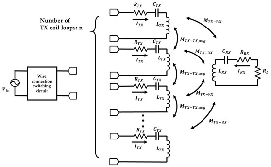
Figure 4.
The equivalent circuit of a multi-split TX coil system with loops to calculate the capacitance values of each TX coil.
The inductance value of each TX coil is , the mutual inductance between each TX coil and RX coil is , and the average value of the mutual inductance between the TX coil loop and the other TX coils is identical to . represents the angular frequency, which can be calculated by multiplying by the operating frequency. The resonant capacitance value for the proposed idea is calculated by considering the mutual inductance values between a single TX coil and the other split TX coils. Because the coupling coefficients between all TX coils are not identical, the average value is used in the derived formula.
The calculated RX current () and corresponding magnitude, derived from Kirchhoff’s voltage law (KVL) equation based on the equivalent circuit of the multi-split TX coil shown in Figure 4, are as follows:
The value of that maximizes the magnitude of the RX current () for maximum output power can be calculated by finding the point where the denominator in Equation (10) is minimized. The value is calculated as follows:
The proposed tunable multi-split TX coil system uses different capacitance values for the TX coil depending on whether it is operating in modes 1, 2, or 3. As previously mentioned, assuming that the inductance value of each TX coil is identical to , the TX coil inductance value is approximately for mode 1, for mode 2, and for mode 3. As expressed by Equation (11), the tuned capacitance of the TX coil is influenced significantly by the mutual inductance between the TX coils (). The capacitance values for each mode, considering , are presented in Table 2.
Table 2.
The formula for the capacitance values of each TX coil depending on the mode shift.
3. Simulation Verification
In this section, the proposed tunable multi-split TX coil is verified using a 3D electromagnetic (EM) solver (ANSYS MAXWELL, AnsysEM v221) and EDA software version 5 (Keysight, Advanced Design System, MINT) for circuit simulation. Three coil modes were created to be verified with the 3D EM solver. The coil parameter values, in this case, the inductances, were obtained from the 3D EM solver and were then input into the circuit simulation. The input current, voltage, and efficiency of the three modes at the same output power are compared.
3.1. Simulation Setup for Mode 1,2, and 3
Table 3 shows the physical parameters of the TX and RX coils, and Table 4 shows the electrical parameters of the 3D EM solver. TX coil connections are tunable with switching elements, as mentioned above. Figure 5 shows the simulation setup for the designed coil of modes 1, 2, and 3 using the 3D EM solver and the simplified equivalent circuit for each mode in the circuit simulation.
Table 3.
The physical parameters used in the 3D EM simulation.
Table 4.
The electrical parameters of TX and RX coils in the conventional system, as analyzed through a 3D EM simulation, with variations in the airgap.
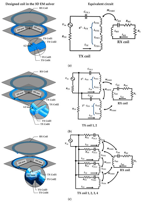
Figure 5.
The setup for the 3D EM solver and equivalent circuit for each mode: (a) mode 1, (b) mode 2, and (c) mode 3.
As shown in Table 4 and Table 5, the inductance values of each TX loop for each mode follow the previously explained theory, being about 16 times greater in mode 1 and four times greater in mode 2 compared to those in mode 3. was calculated based on Equation (11). As indicated in Table 6, the operating frequency is 85 kHz, the output power is fixed at 200 W, and the load resistance is .
Table 5.
The electrical parameters of TX and RX coils in the proposed system, as analyzed through a 3D EM simulation, with variations in the airgap.
Table 6.
The electrical parameters used in the circuit simulation.
can be calculated as follows:
When a conventional TX coil with a single loop is divided into loops, each TX loop inductance becomes . for modes 1, 2, and 3 can be calculated according to Equation (12). Table 7 shows the change in for the three modes when the airgap between the TX and RX coil is adjusted from 50 mm to 250 mm with 50 mm sweeps.
Table 7.
variations depending on the change in the airgap between the TX and RX coils.
3.2. Input Current and Input Voltage Variation of Each Mode with the Same Output Power
Table 8 and Table 9 present the measured values of the input voltage (), the total input current (), the total input impedance and the PTE from the output of the inverter to the input of the rectifier (coil-to-coil PTE) for the conventional (mode 1) and the proposed system with mode switching applied in both cases under identical output power conditions.
Table 8.
The electrical values depending on the airgap variations in the mode 1 (conventional) system.
Table 9.
The electrical values depending on the airgap variations in the proposed system.
Figure 6 shows the input voltage values required to maintain constant output power in both the conventional and proposed systems. The conventional system, equivalent to mode 1, uses a single-loop TX coil. The proposed system operates selectively between modes 1, 2, and 3 to accommodate various airgaps. As increases, the proposed system operates sequentially through modes 3, 2, and 1.
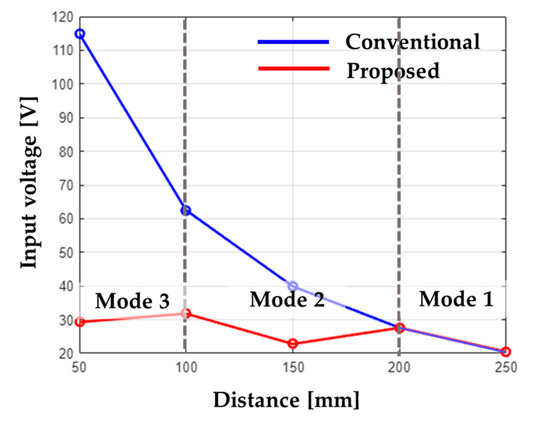
Figure 6.
The input voltage values of the conventional and proposed system with varying airgaps when the output power of the load is fixed at 200 W.
When the airgap varies from 50 mm to 250 mm, the conventional system requires an input voltage ranging from a minimum of 20.5 V to a maximum of 114.9 V to maintain constant output power of 200 W, according to Figure 6 and Table 9. This means an increase of approximately 460.49%. In contrast, the proposed system requires an input voltage ranging from a minimum of 20.5 V to a maximum of 29.3 V to maintain 200 W of output power, according to Figure 7 and Table 10, an increase of only 42.93%.
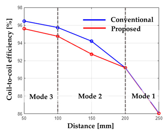
Figure 7.
Coil to coil efficiency, from the output power of the inverter to the input power of the rectifier.
Table 10.
The minimum and maximum values of the input voltage (, ) required to maintain a constant output power of 200 W for both the conventional system and the proposed system when the airgap varies from 50 mm to 250 mm.
Hence, even if changes due to variations in the airgap between the TX and RX coils, the proposed system can provide stable output power through mode shifting with smaller variations in the input voltage compared to the conventional system.
The coil-to-coil PTE graph for the three modes in Figure 7 depends on the variations in the airgaps. When operating the system in modes 3, 2, and 1 sequentially, the PTE decreases gradually. The difference between the maximum and minimum efficiency points in the conventional system is approximately 10.43%. When switching between modes 1, 2, and 3 depending on the airgap variations, the difference between the highest and lowest PTE is about 9.56%.
Equations (13)–(15) present the PTE () formula, expressed in terms of the mutual inductance between the TX and RX coils (), the total impedance of each TX coil () and RX coil (), and the angular frequency () and the load resistance () [12]. When the system operates in an over-coupling state, the PTE differences among the three modes decrease because, as shown in Figure 2, the PTE becomes saturated as increases. According to Equation (15), the reason for this saturation in the PTE in an over-coupling condition is that as increases, also increases, making its influence more dominant compared to the total impedance of the TX coil. Therefore, even if the mode of the system is switched as the airgap varies, if the system operates in modes 3 and 2 when is large, the PTE reduction is minimized.
4. Experimental Section
The proposed method was verified experimentally. The input voltage, current, and coil-to-coil efficiency from the inverter to the rectifier were measured as the airgap of the WPT system changed to 100 mm, 150 mm, and 200 mm. Measurements were taken for both the operation of a conventional single-coil system and during sequential switching through modes 3, 2, and 1.
4.1. Experimental Setup
Figure 8 shows the experimental setup used to verify the proposed method. The TX unit included a DC power supply, a full-bridge inverter, and TX coils, while the RX unit consisted of an RX coil, a rectifier, and a DC load. The operating frequencies of the conventional and proposed system were both 85 kHz and the load resistance is 1 .
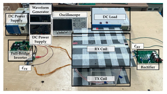
Figure 8.
The experimental setup of the proposed system.
Table 11 and Table 12 show the inductance values of the TX and RX coils, , and the parasitic resistance values of the conventional and proposed WPT system, measured by an impedance analyzer (KEYSIGHT E4990A, Keysight, Santa Rosa, CA, USA). The calculated capacitance values of each TX coil (, , and ), based on Equation (11), were implemented.
Table 11.
The electrical parameters of the TX and RX coils measured with an impedance analyzer, and the calculated capacitance values in the conventional system with variations in the airgap.
Table 12.
The electrical parameters of the TX and RX coils measured with an impedance analyzer, and the calculated capacitance values in the proposed system with variations in the airgap.
4.2. Experimental Result
Upon airgap changes to 100 mm, 150 mm, and 200 mm, measurements were taken for the input voltage and current required to achieve the same power of 20 W when operating with a conventional single coil, as well as the proposed system, operating in modes 3, 2, and 1 sequentially. The rates were then compared.
When the airgap changes, the conventional system requires an input voltage ranging from a minimum of 10.78 V to a maximum of 25.53 V to sustain a constant output power of 20 W, as shown in Table 13. This represents an increase of approximately 136.83%. In contrast, the proposed system needs an input voltage between 7.63 V and 10.78 V to maintain an output power of 20 W, as indicated in Table 14, which is an increase of only 41.28%.
Table 13.
The measured values through the experiment depending on the airgap variations in the mode 1 (conventional) system.
Table 14.
The values measured experimentally depending on airgap variations in the proposed system.
In a WPT system with varying airgaps, the proposed system achieves a constant output power of 20 W with reduced variations in the input voltage. The PTE decreases by up to 2.5% compared to that in the conventional system due to the increased current. However, this PTE reduction can be mitigated by properly adjusting the mode switching points.
5. Discussion
The simulation results showed that the proposed system can provide consistent and stable output power through mode shifting with particular current and voltage values. The reason for setting the TX coil turns of the proposed system to four turns is to ensure that the relationship between each TX coil loop and the RX coil is symmetrical in each mode. For high-power applications, where the diameter of the coil is large enough and the length of the wire in each loop is similar, the relationship between each TX coil loop and the RX coil remains symmetrical when a single coil is split. This symmetry ensures that the coupling coefficient between each TX coil loop and the RX coil is uniform while also confirming that the coupling coefficients among the TX coils are similar, thereby preventing phase differences in the currents between the TX coils. This approach simplifies the design of the resonant capacitance of each TX coil.
If the number of turns of the TX coil is increased or if thinner coils are designed, a stable output power supply can be achieved at various points with less variation in both the input current and voltage. For example, in the proposed system, mode 2 and mode 3 have inductance values that are four and 16 times, respectively, that of mode 1, allowing a consistent output power supply without adjusting the current only at points where is two and four times higher. If thinner coils with a third of the current thickness and twelve turns are used, it becomes possible to set more diverse modes depending on the coil connections. A constant output power supply to the load can be achieved at points where is two, three, four, and six times higher compared to the single-loop TX coil.
In the proposed system, eight Silicon Carbide (SiC) MOSFET switches were used for mode switching. Conduction losses are more significant than switching losses with regard to losses caused by switches in the proposed system. To minimize the reduction in efficiency due to conduction losses, MOSFET switches with low conduction losses were selected. MOSFET switches with a turn-on resistance ( of 11 mΩ were used.
When voltage levels increase, high-performance DC/DC buck–boost converters are essential for maintaining voltage regulation and ensuring constant power delivery to the load with an efficiency of around 90% [31]. In WPT systems like those used in electric vehicles, where airgap variations are relatively fixed, consistent output power can be achieved with constant voltage and current through mode switching in the proposed multi-split system. Although SiC MOSFETs generally have higher conduction losses than traditional Silicon MOSFET switches, advancing this approach could potentially replace buck–boost converters and achieve higher efficiency compared to systems using conventional buck–boost converters. The coil-to-coil PTE shown in Table 8 and Table 9 is further detailed in Table 15, considering the losses from buck–boost converters in conventional WPT systems (, conventional) and conduction losses at 175 °C in SiC MOSFET switches in proposed systems (, proposed), respectively.
Table 15.
Coil-to-coil PTE, considering the losses from buck–boost converters in the conventional WPT system and conduction losses at 175 °C in SiC MOSFET switches in the proposed system.
Increasing the number of turns to operate with diverse modes requires more switches, which in turn will lead to higher conduction losses. Although diverse modes can maintain consistent output power with less input voltage variation when the airgap changes, it would be disadvantageous in terms of efficiency. On the other hand, if the system is designed with TX coils with fewer turns, operating in fewer modes, larger input voltage variations will arise compared to when the system is operated in more diverse modes, causing a PTC reduction. However, using fewer switches offers advantages in terms of system size, cost, and efficiency.
Therefore, by selecting the appropriate coil thickness and number of turns, it is expected that a system can be designed to deliver consistent power across varying airgaps with small variations in the input voltage. This can be achieved with a smaller system size and at a reduced cost by simply adjusting the coil connections.
When increases due to variations in the airgap, the proposed system controls the inductance value of the TX coils through mode switching to increase the PTC and reduce the variation in the input voltage. However, there is another option to increase the PTC: changing the switching frequency of the inverter.
From 200 mm to 250 mm, the conditions are identical to those in Figure 7. Therefore, simulations were conducted to achieve a maximum output power of 200 W by adjusting the switching frequency of the inverter when the airgap varies from 50 mm to 200 mm. Table 16 specifies the minimum input voltage required to achieve 200 W of output power, the corresponding inverter switching frequency, and coil-to-coil PTE. By adjusting the inverter switching frequency, the voltage variation needed to maintain 200 W of power was 80%. This shows that the voltage variation is greater compared to that in the proposed system. In other words, the proposed system demonstrates better performance in improving the PTC. Additionally, there is a decrease in the efficiency compared to the efficiency rates shown in Figure 8. The method of improving the PTC by changing the inverter switching frequency has the disadvantage of greater input voltage variation and a wider range of switching frequencies compared to the proposed system.
Table 16.
The minimum input voltage required to achieve the maximum output power of 200 W when the airgap varies from 50 mm to 200 mm.
6. Conclusions
In this paper, a tunable multi-split TX coil is proposed to maintain a stable and consistent output power supply to the load, regardless of variations in the coupling coefficients caused by changes in the distance between the TX and RX coils. A tunable multi-split TX coil can operate in various modes depending on how the wire connections between each TX coil are configured. The method proposed here involves simply adjusting the inductance value of the TX coil for various conditions, using the same amount of coil as a conventional single-loop TX coil.
In a simulation, a TX coil with four loops operates in three modes: four turns connected as a single loop, two TX loops each with two turns, and four TX loops each with one turn. The results show that by adjusting the TX coil to three different modes as the airgap varies from 50 mm to 250 mm, consistent output power is achieved with smaller variations in the input voltage compared to the conventional system. The conventional system requires an input voltage increase of approximately 460.49%, while the corresponding values that the proposed system requires are 42.93%.
For experimental verification, as the airgap varied between 100 mm, 150 mm, and 200 mm, the conventional system required an input voltage ranging from a minimum of 10.78 V to a maximum of 25.53 V, representing an increase of approximately 136.83%. In contrast, the proposed system operating in modes 3, 2, and 1 sequentially needed the input voltage to be between 7.63 V and 10.78 V to maintain an output power of 20 W, representing an increase of only 41.28%. In a WPT system with varying airgaps, the proposed system achieved constant output power of 20 W with reduced variations in the input voltage. Although the PTE decreased by up to 2.5% compared to that in the conventional system, this reduction can be mitigated by properly adjusting the mode switching points.
This approach provides stable power with a standardized and simplified TX coil structure. A typical DC/DC buck–boost converter adjusts the voltage and current values to maintain consistent and stable output power when the airgap changes. However, when the airgap variation becomes significant, a DC/DC converter with higher specifications is required, increasing the cost of the system due to the need for components that can withstand higher voltages. The proposed idea can supplement such DC/DC converters. This solution can be applied to a wider range of airgap variations. It can help overcome the limitations related to cost and converter loss issues.
The method proposed here is expected to standardize the transmitting units of WPT applications in various mobility fields, thereby reducing systems’ cost, complexity, and size. It enables a simplified and stable power supply system over a wide range of airgaps.
Author Contributions
Conceptualization, Y.J. and J.K.; Methodology, H.L.; Software, S.L.; Validation, S.L.; Formal analysis, C.L.; Resources, J.R.; Data curation, S.H.; Writing—original draft, Y.J.; Writing—review & editing, S.R.; Visualization, S.W.; Supervision, S.A. All authors have read and agreed to the published version of the manuscript.
Funding
This work was supported by Institute of Information & communications Technology Planning & Evaluation (IITP) grant funded by the Korea government (MSIT) (No. RS-2024-00399304, Development of Lightweight Materials and Electromagnetic Field Reduction Technology for Wireless Power Transfer System for 22 kW Electric Vehicles). This work was also partly supported by the Institute of Information & communications Technology Planning & Evaluation (IITP) grant funded by the Korea government (MSIT) (No. 2020-0-00839, Development of Advanced Power and Signal EMC Technologies for Hyper-connected E-Vehicle, 50%).
Data Availability Statement
The original contributions presented in the study are included in the article, further inquiries can be directed to the corresponding author.
Conflicts of Interest
Author Jedok Kim is employed by Samsung Electronics Co., Ltd. The remaining authors declare that the research was conducted in the absence of any commercial or financial relationships that could be construed as a potential conflict of interest.
References
- Zhang, Z.; Pang, H.; Georgiadis, A.; Cecati, C. Wireless Power Transfer—An Overview. IEEE Trans. Ind. Electron. 2019, 66, 1044–1058. [Google Scholar] [CrossRef]
- Cheng, Z.; Lei, Y.; Song, K.; Zhu, C. Design and Loss Analysis of Loosely Coupled Transformer for an Underwater High-Power Inductive Power Transfer System. IEEE Trans. Magn. 2015, 51, 8401110. [Google Scholar] [CrossRef]
- Zhou, J.; Li, D.; Chen, Y. Frequency Selection of an Inductive Contactless Power Transmission System for Ocean Observing. Ocean Eng. 2013, 60, 175–185. [Google Scholar] [CrossRef]
- Khan, S.R.; Pavuluri, S.K.; Cummins, G.; Desmulliez, M.P.Y. Wireless Power Transfer Techniques for Implantable Medical Devices: A Review. Sensors 2020, 20, 3487. [Google Scholar] [CrossRef]
- Jawad, A.M.; Jawad, H.M.; Nordin, R.; Gharghan, S.K.; Abdullah, N.F.; Abu-Alshaeer, M.J. Wireless Power Transfer with Magnetic Resonator Coupling and Sleep/Active Strategy for a Drone Charging Station in Smart Agriculture. IEEE Access 2019, 7, 139839–139851. [Google Scholar] [CrossRef]
- Li, S.; Mi, C.C. Wireless Power Transfer for Electric Vehicle Applications. IEEE J. Emerg. Sel. Top. Power Electron. 2015, 3, 4–17. [Google Scholar] [CrossRef]
- Wang, C.-S.; Covic, G.A.; Stielau, O.H. Power Transfer Capability and Bifurcation Phenomena of Loosely Coupled Inductive Power Transfer Systems. IEEE Trans. Ind. Electron. 2004, 51, 148–157. [Google Scholar] [CrossRef]
- Xiao, Y.; Liu, C. Direct Load Voltage Control for Electrolytic Capacitorless Wireless Power Transfer System Without DC/DC Converter. IEEE Trans. Ind. Electron. 2021, 68, 8039–8048. [Google Scholar] [CrossRef]
- Tran, M.T.; Thekkan, S.; Polat, H.; Tran, D.-D.; El Baghdadi, M.; Hegazy, O. Inductive Wireless Power Transfer Systems for Low-Voltage and High-Current Electric Mobility Applications: Review and Design Example. Energies 2023, 16, 2953. [Google Scholar] [CrossRef]
- Kim, H.-J.; Hirayama, H.; Kim, S.; Han, K.J.; Zhang, R.; Choi, J.-W. Review of Near-Field Wireless Power and Communication for Biomedical Applications. IEEE Access 2017, 5, 21264–21285. [Google Scholar] [CrossRef]
- Shu, X.; Xiao, W.; Zhang, B. Wireless Power Supply for Small Household Appliances Using Energy Model. IEEE Access 2018, 6, 69592–69602. [Google Scholar] [CrossRef]
- Leng, Y.; Zhang, X.; Qiu, C.; Liu, Z.; Song, J. Coupling Coefficient Calculation and Optimization of Positive Rectangular Series Coils in Wireless Power Transfer Systems. Heliyon 2023, 9, e10206. [Google Scholar] [CrossRef]
- Chen, L.; Liu, S.; Zhou, Y.C.; Cui, T.J. An Optimizable Circuit Structure for High-Efficiency Wireless Power Transfer. IEEE Trans. Ind. Electron. 2013, 60, 339–349. [Google Scholar] [CrossRef]
- Kim, J.; Ahn, S. Dual Loop Reactive Shield Application of Wireless Power Transfer System for Leakage Magnetic Field Reduction and Efficiency Enhancement. IEEE Access 2021, 9, 118307–118323. [Google Scholar] [CrossRef]
- Huh, S.; Kim, J.; Kim, J.-I.; Kim, J.; Lee, S. Transmitter Coils Selection Method for Wireless Power Transfer System With Multiple Transmitter Coils and Single Receiver Coil. IEEE Trans. Power Electron. 2023, 38, 4092–4109. [Google Scholar] [CrossRef]
- Ghorbani Eftekhar, M.; Ouyang, Z.; Andersen, M.A.E.; Andersen, P.B.; Ribeiro, L.A.S.; Schaltz, E. Efficiency Study of Vertical Dis-tance Variations in Wireless Power Transfer for E-Mobility. IEEE Trans. Magn. 2016, 52, 1–4. [Google Scholar] [CrossRef]
- Ryu, K.; Jeong, J. Automatic Adaptation of Multi-Loop Wireless Power Transfer to Variable Coupling between Transmit and Receive Coils. Energies 2018, 11, 1789. [Google Scholar] [CrossRef]
- Kim, T.-H.; Yun, G.-H.; Lee, W.Y.; Yook, J.-G. Asymmetric Coil Structures for Highly Efficient Wireless Power Transfer Systems. IEEE Trans. Microw. Theory Tech. 2018, 66, 3443–3451. [Google Scholar] [CrossRef]
- Kim, J.; Jeong, J. Range-Adaptive Wireless Power Transfer Using Multiloop and Tunable Matching Techniques. IEEE Trans. Ind. Electron. 2015, 62, 6233–6241. [Google Scholar] [CrossRef]
- Lee, W.; Ahn, D. Wireless Power Transfer under Wide Distance Variation Using Dual Impedance Frequency. Electronics 2020, 9, 110. [Google Scholar] [CrossRef]
- Lee, J.; Lim, Y.-S.; Yang, W.-J.; Lim, S.-O. Wireless Power Transfer System Adaptive to Change in Coil Separation. IEEE Trans. Antennas Propag. 2014, 62, 889–897. [Google Scholar] [CrossRef]
- Huh, S.; Koo, J.-I.; Jeong, O.; Ahn, S. Maximizing Output Power Using a Magnetic Energy Harvesting System Considering the Relationship Between Harvesting Time and Induced Voltage Due to a Change of Airgap. IEEE Access 2024, 12, 5947–5959. [Google Scholar] [CrossRef]
- Lee, C.; Woo, S.; Shin, Y.; Rhee, J.; Moon, J.; Ahn, S. EMI Reduction Method for Wireless Power Transfer Systems with High Power Transfer Efficiency Using Frequency Split Phenomena. IEEE Trans. Electromagn. Compat. 2022, 64, 1683–1693. [Google Scholar] [CrossRef]
- Niu, W.-Q.; Chu, J.-X.; Gu, W.; Shen, A.-D. Exact Analysis of Frequency Splitting Phenomena of Contactless Power Transfer Sys-tems. IEEE Trans. Circuits Syst. I Regul. Pap. 2013, 60, 1670–1677. [Google Scholar] [CrossRef]
- Huang, R.; Zhang, B.; Qiu, D.; Zhang, Y. Frequency Splitting Phenomena of Magnetic Resonant Coupling Wireless Power Trans-fer. IEEE Trans. Magn. 2014, 50, 1–4. [Google Scholar] [CrossRef]
- Beh, T.C.; Kato, M.; Imura, T.; Oh, S.; Hori, Y. Automated Impedance Matching System for Robust Wireless Power Transfer via Magnetic Resonance Coupling. IEEE Trans. Ind. Electron. 2013, 60, 3689–3698. [Google Scholar] [CrossRef]
- Deng, Q.; Li, S.; Ren, L.; Mi, C.C. Frequency-Dependent Resistance of Litz-Wire Square Solenoid Coils and Quality Factor Opti-mization for Wireless Power Transfer. IEEE Trans. Ind. Electron. 2016, 63, 2825–2837. [Google Scholar] [CrossRef]
- Ahn, D.; Kim, S.-M.; Kim, S.-W.; Moon, J.-I.; Cho, I.-K. Wireless Power Transfer Receiver with Adjustable Coil Output Voltage for Multiple Receivers Application. IEEE Trans. Ind. Electron. 2019, 66, 4003–4012. [Google Scholar] [CrossRef]
- Nair, V.V.; Choi, J.R. An Efficiency Enhancement Technique for a Wireless Power Transmission System Based on a Multiple Coil Switching Technique. Energies 2016, 9, 156. [Google Scholar] [CrossRef]
- Zhang, Y.; Chen, S.; Li, X.; Tang, Y. Design of High-Power Static Wireless Power Transfer via Magnetic Induction: An Overview. CPSS Trans. Power Electron. Appl. 2021, 6, 281–297. [Google Scholar] [CrossRef]
- Fu, M.; Ma, C.; Zhu, X. A Cascaded Boost–Buck Converter for High-Efficiency Wireless Power Transfer Systems. IEEE Trans. Ind. Inform. 2014, 10, 1972–1980. [Google Scholar] [CrossRef]
Disclaimer/Publisher’s Note: The statements, opinions and data contained in all publications are solely those of the individual author(s) and contributor(s) and not of MDPI and/or the editor(s). MDPI and/or the editor(s) disclaim responsibility for any injury to people or property resulting from any ideas, methods, instructions or products referred to in the content. |
© 2024 by the authors. Licensee MDPI, Basel, Switzerland. This article is an open access article distributed under the terms and conditions of the Creative Commons Attribution (CC BY) license (https://creativecommons.org/licenses/by/4.0/).