Article

The Feasibility Study of In Situ Conversion of Oil Shale Based on Calcium-Oxide-Based Composite Materia Hydration Exothermic Reaction

1
Key Laboratory of Shale Gas and Geoengineering, Institute of Geology and Geophysics, Chinese Academy of Sciences, Beijing 100029, China
2
Innovation Academy for Earth Science, Chinese Academy of Sciences, Beijing 100029, China
3
College of Earth and Planetary Sciences, University of Chinese Academy of Sciences, Beijing 100049, China
*
Author to whom correspondence should be addressed.
Energies 2024, 17(8), 1798; https://doi.org/10.3390/en17081798
Submission received: 6 March 2024 / Revised: 27 March 2024 / Accepted: 3 April 2024 / Published: 9 April 2024
(This article belongs to the Section H: Geo-Energy)

Abstract

:
Oil shale, as a vast potential resource, is considered an important alternative energy source, and its effective development and economic utilization are of significant importance in alleviating the contradiction between energy supply and demand. Presently, the in situ conversion technology for oil shale has gained significant global attention, with numerous extraction methods undergoing active research and development. One of these methods is the in situ conversion of oil shale based on the hydration reaction of calcium-oxide-based composite material (CaO-CM). This approach harnesses the heat produced by the reaction between CaO-CM and water as a heat source for the pyrolysis of oil shale. This paper conducted experiments to assess the feasibility of temperature associated with this method. The feasibility study mainly includes two aspects: First, it is necessary to investigate whether the temperature generated by the hydration reaction of CaO-CM can meet the temperature requirements for the pyrolysis of oil shale. Through pyrolysis experiments of Xinjiang oil shale, the minimum temperature required for oil shale pyrolysis was determined to be 330 °C. High-temperature and high-pressure reaction vessels were employed to explore the temperature generated by the hydration reaction of CaO-CM. The results show that with the increase in environment pressure, environment temperature, and reaction mass, the maximum temperature generated by the hydration reaction of CaO-CM also increases (reach 455.5 °C), meeting the temperature requirements for the pyrolysis of oil shale. Second, the study evaluates whether the hydration reaction of CaO-CM can induce pyrolysis hydrocarbons of the oil shale. Through the pyrolysis experiments of oil shale based on the hydration reaction of CaO-CM, the changes in the content of pyrolysis hydrocarbons (S2) in oil shale before and after pyrolysis are measured. The results show that under 10 MPa pressure, the content of pyrolysis hydrocarbons in the oil shale decreased from 40.96 mg/g to 0.08 mg/g after pyrolysis. This confirms the feasibility of the temperature conditions for the in situ conversion of oil shale based on the hydration reaction of CaO-CM.

1. Introduction

In the face of the critical situation regarding oil and gas resources, finding diverse and suitable alternatives to replace the depleting reserves has become a crucial strategic concern for national energy development. Oil shale, a solid combustible organic sedimentary rock with high ash content and oil content exceeding 3.5%, can be obtained through low-temperature distillation, typically possessing a calorific value higher than 4.18 MJ/kg. It is categorized as an unconventional oil and gas resource [1]. In China, the geological resources of oil shale have reached 719,937 million tons, with technically recoverable resources of high-maturity shale oil estimated at 145 × 108 t [2,3,4], and technically recoverable resources of medium-low maturity shale oil from in situ conversion techniques estimated at approximately (700~900) × 108 t, which is three to four times the total recoverable resources of conventional petroleum technologies in China [5], making it a significant strategic resource for China’s energy security. Consequently, oil shale is considered a vital energy source for future oil and gas replacements [6,7].
Oil shale extraction technologies are divided into surface retorting and in situ conversion. Surface retorting is generally only applicable to exposed oil shale or shallow reservoirs. However, this extraction method suffers from low utilization, small scale, high costs, and environmental pollution from emitted gases, wastewater, dust, etc. Additionally, surface retorting generates large amounts of waste residue that is not easily recyclable, and since China’s oil shale resources are mostly concentrated in deep-to-middle layers, this method cannot fully exploit oil shale resources. In contrast, in situ conversion extraction technology boasts high extraction efficiency, superior product quality, space-saving characteristics, and minimal environmental pollution, thereby shaping the development trend of the oil shale industry [8,9,10,11].
The in situ conversion methods of oil shale primarily involve heating the shale reservoirs, which can be categorized into four types based on the heating mechanisms: the electric heating method, the convection heating method, the combustion heating method, and the radiation heating method. The electric heating method primarily converts electrical energy into heat energy to thermally decompose organic matter for oil shale extraction [12,13]. One representative technique is the in situ conversion process (ICP) introduced by Shell in the 1970s [14,15], which involves drilling holes into the reservoir and placing electric heaters to heat the oil shale. ExxonMobil has proposed the Electrofra™ technology, which involves hydraulic fracturing of the oil shale reservoir followed by filling the fractures with conductive materials for heating the oil shale [16,17,18]. Independent Energy Partners (IEP) introduced the in situ distillation technique, employing geothermal fuel cells (GFC) to place high-temperature fuel cell groups in the formation to decompose kerogen and produce oil and gas [19]. Convection heating involves injecting high-temperature substances into shale oil reservoirs to exploit oil shale by heating through convection. Chevron’s CRUSH technology is one such method [20,21,22], where high-temperature fluids are injected into pre-fractured shale reservoirs for convection heating to extract oil and gas. Petro Probe proposed a method involving injecting superheated air to induce oil shale pyrolysis, bringing light hydrocarbon gas–liquid to the surface [23]. The US Shale Oil Corporation has proposed the CCR method, which involves arranging horizontal wells vertically. The lower horizontal well is used for heating, while the upper horizontal well is used for extraction [24,25]. Taiyuan University of Technology has proposed steam injection (MTI) technology, which involves fracturing interconnect wells and injecting high-temperature steam into the wells to pyrolysis oil shale [26,27]. Jilin University has proposed the near-critical water (NCW) method for the in situ conversion of oil shale, utilizing near-critical water as a heat and mass transfer medium and extraction agent to induce the decomposition of kerogen organic matter, thereby generating oil and gas [28]. Combustion heating involves on-site combustion to generate heat for heating the reservoirs to extract oil. Laramie Energy Technology Center (LETC) utilizes hydraulic fracturing and explosion methods to fracture oil shale formations, igniting oil shale at injection wells, continuously injecting air, and sustaining combustion [29]. Jilin University, in collaboration with Israeli scientists, has jointly developed the thermal spalling activation (TSA) method for the in situ conversion of oil shale. It is a low-energy input and highly efficient heating and cracking technology [30]. Radiation heating involves heating shale oil reservoirs using microwave technology [31]. In the late 1970s, Lawrence Livermore National Laboratory (LLNL) proposed heating oil shale using wireless frequencies, utilizing vertically arranged electrode combinations to slowly heat deep shale formations. In the late 20th century, the RF/CF technology of the Raytheon Corporation was derived from radio frequency heating and supercritical fluid heat transfer technology [31]. The Global Resource Corporation (GRC) developed a technique by which to heat shale at specific microwave frequencies and equipment for extracting oil and gas [31].
However, at present, these in situ conversion techniques are still in the research and experimental stage, facing challenges such as long heating time, low efficiency of rock heating, poor technical and economic viability, environmental pollution, and reduced reservoir stability, which are hindering their commercialization. Therefore, there is an urgent need to explore in situ conversion methods for shale oil that are not only technologically viable but also economically and environmentally sustainable. Li et al. proposed the theory and method of in situ chemical thermogenesis for oil shale extraction based on the principles of material and energy balance [32]. The core of this method is to utilize the heat generated by the hydration reaction of calcium oxide to pyrolyze oil shale. They theoretically demonstrated the technical feasibility of this method in terms of temperature, heat supply, and solid-phase volume changes. To prevent calcium oxide from reacting with water prematurely, they conducted research on composite materials based on calcium oxide. Based on this, this paper conducted experimental research on the feasibility of temperature associated with this calcium-oxide-based composite material (CaO-CM). Xinjiang oil shale was chosen as the research object, and the temperature required for oil shale pyrolysis was determined based on experiments conducted using a muffle furnace to heat the oil shale. Through experiments conducted in a high-temperature and high-pressure reactor vessel, the hydration reaction temperature of CaO-CM under different pressures, different environment temperatures, and reaction quantity was investigated, confirming that the temperature generated by the hydration reaction of CaO-CM can meet the temperature requirements for oil shale pyrolysis. Finally, oil shale pyrolysis experiments were conducted based on the hydration reaction of CaO-CM, and the changes in the content of pyrolysis hydrocarbons (S2) before and after pyrolysis were measured. The feasibility of this method in terms of temperature provision was demonstrated by analyzing the experimental results.

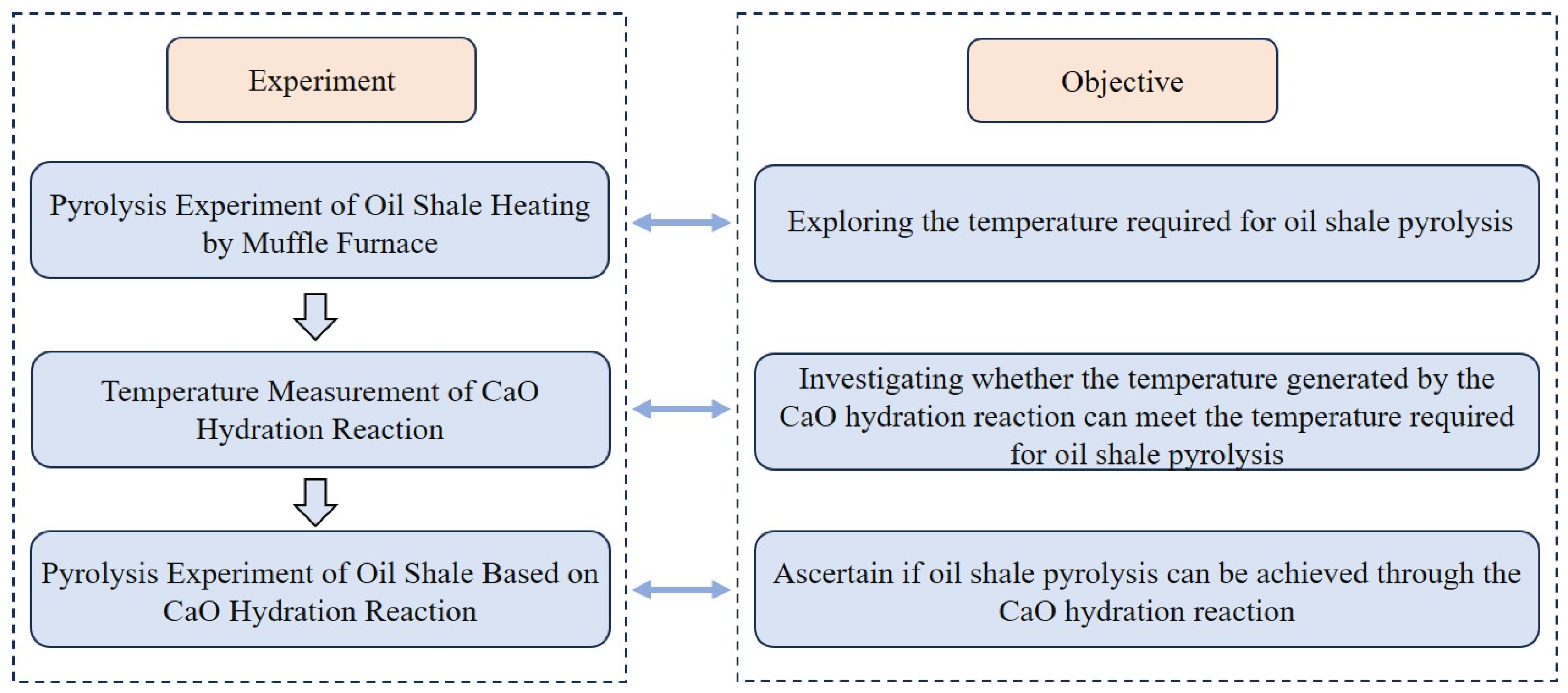
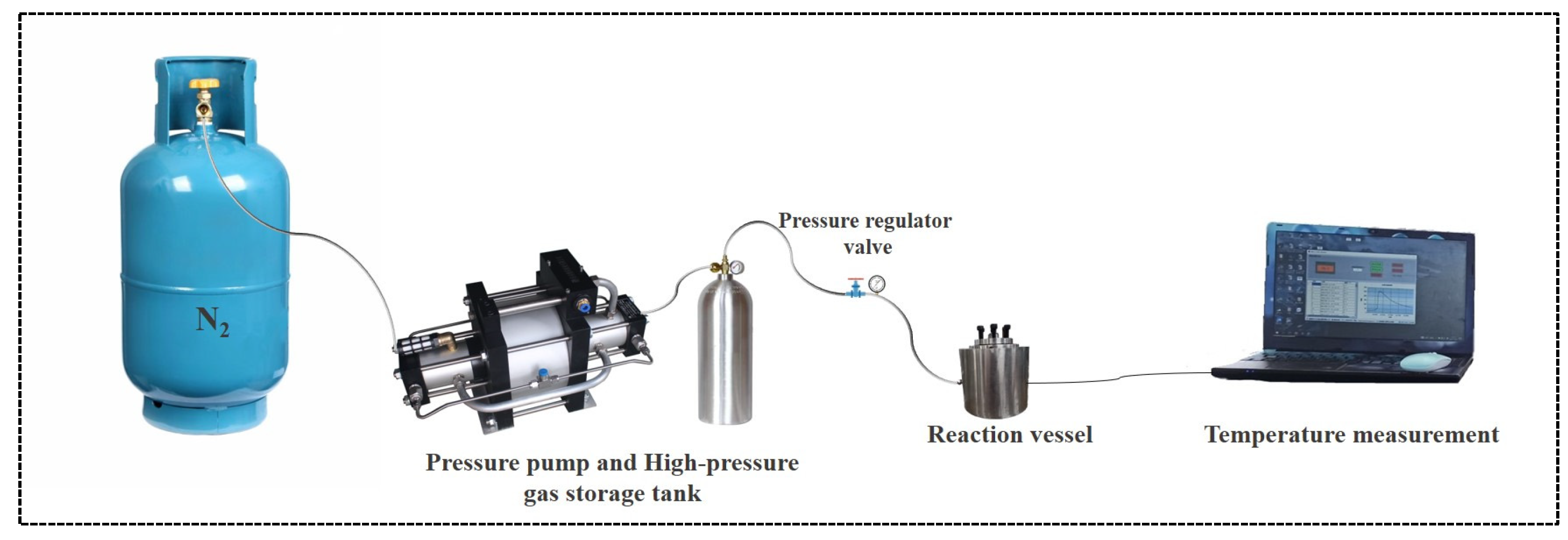
2. Experimental Design and Instrumentation Introduction

The calcium-oxide-based composite material used in this paper is shown in Figure 1. The material is a white powder with a certain degree of hydrophobicity. This paper mainly explores the feasibility of the in situ conversion of oil shale based on the hydration reaction of CaO-CM in terms of temperature supply. Temperature measurements in this paper were recorded starting from the hydration reaction of the material. The exploration is divided into the following two main research aspects: First, it is essential to determine whether the temperature generated by the hydration reaction of CaO-CM can meet the temperature requirements for the pyrolysis of oil shale. If the temperature produced by the reaction can meet the needs of oil shale pyrolysis, then the in situ conversion of oil shale based on the exothermic reaction of CaO-CM hydration will be feasible in terms of heat supply. The second aspect of the research is to conduct experiments on the pyrolysis of oil shale based on the hydration reaction of CaO-CM at temperatures that can meet the temperature requirements for oil shale pyrolysis. The experiment measures the changes in the content of pyrolysis hydrocarbons before and after oil shale pyrolysis. If there is a significant decrease in the content of pyrolysis hydrocarbons after pyrolysis, it indicates that the heat released by the CaO-CM hydration reaction has facilitated the thermal decomposition of organic matter in oil shale, ultimately resulting in a decrease in pyrolysis hydrocarbon content, thus confirming the feasibility of this method. Conversely, if there is no significant reduction, it demonstrates the infeasibility of the method. The experimental content is divided into three parts: determination of the oil shale pyrolysis temperature, measurement of the temperature of the CaO-CM hydration reaction, and oil shale pyrolysis based on the CaO-CM hydration reaction. The experimental design and objectives are shown in Figure 2. The specific experimental design and equipment used are introduced as follows.

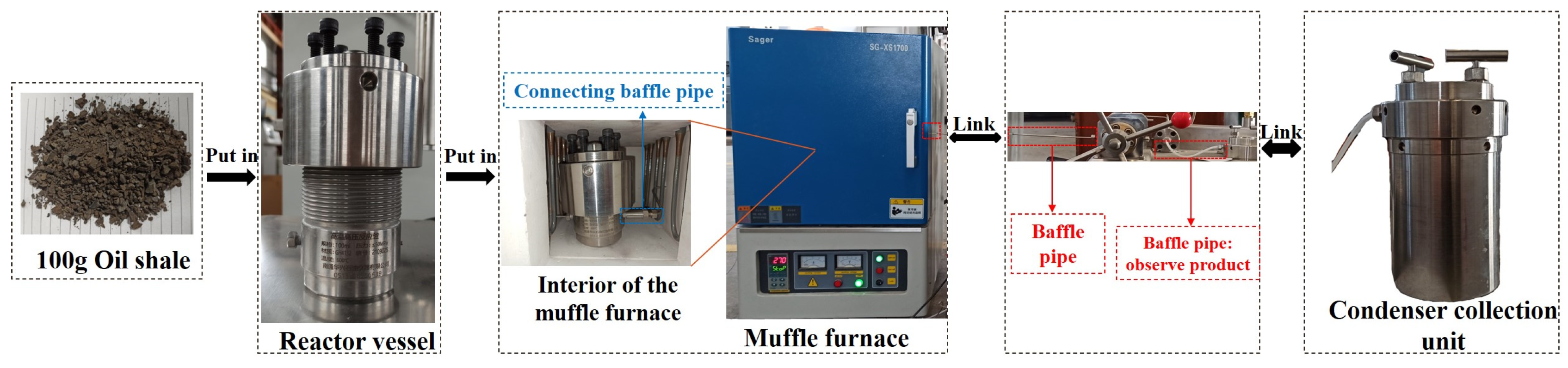
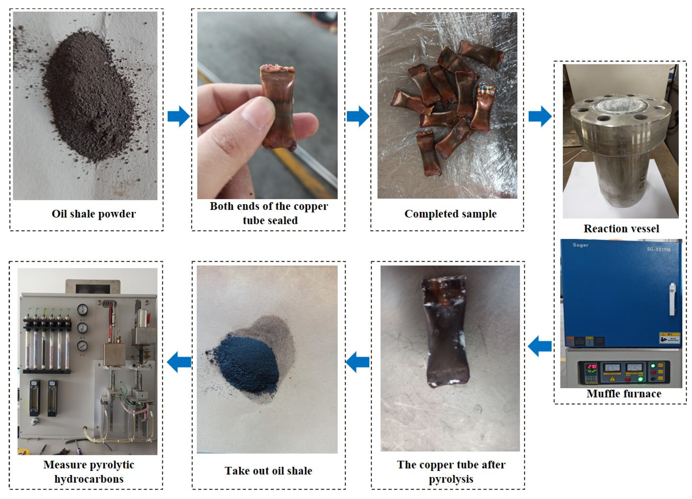
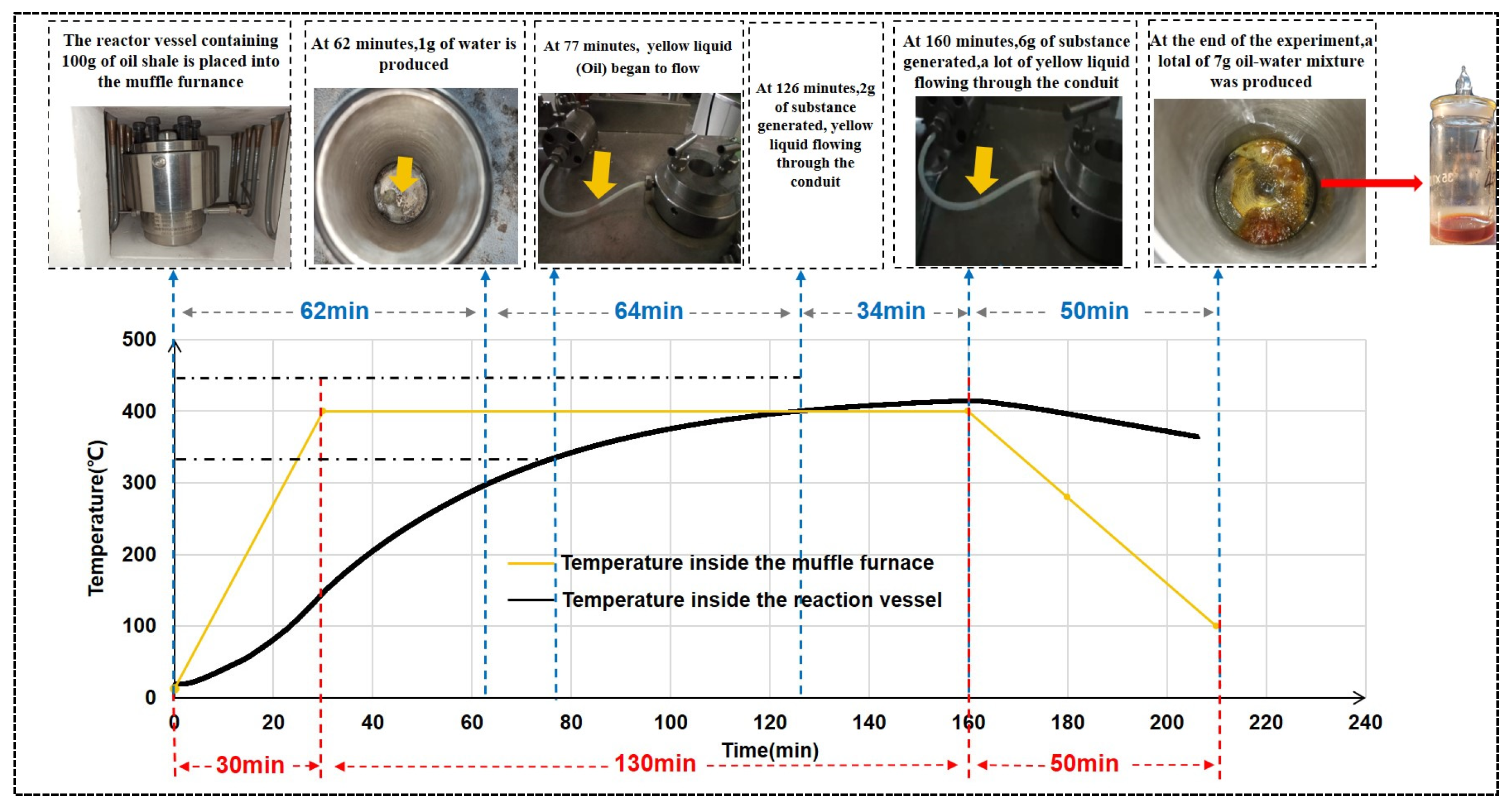
2.1. Pyrolysis Experiment of Oil Shale Heating by Muffle Furnace

The oil shale sample used in the experiment is Xinjiang oil shale. Its color is grey-brown, and its density is 2.3 g/cm3. Through simulated pyrolysis experiments, the content of free hydrocarbons (S1) was 0.77 mg/g, and the content of pyrolysis hydrocarbons (S2) was 40.96 mg/g. Wang et al. conducted proximate and Fischer assay analyses of oil shale from Xinjiang, with their results provided in the corresponding reference [33]. The experimental apparatus consists of a muffle furnace, reaction vessel, and condensation collection device. The equipment parameters are shown in Table 1.
The specific experimental procedure is as follows: First, place 100g of oil shale fragments (with a maximum diameter of 1cm) into the reaction vessel. Place the reaction vessel into the muffle furnace and connect it to the condensation collection device via conduits. Set the heating temperature of the muffle furnace. Set the condensation collection device to −20 °C and observe whether there is any flow of generated substances in the conduits. Set the condensation collection device to −20 °C and observe whether there is any flow of generated substances in the conduits. During the experiment, the weight of the condensation collection device can be measured in real time to determine whether pyrolysis products are being collected and the quantity of the products. The specific experimental procedure and equipment are shown in Figure 3.

2.2. Measure the Temperature of the CaO-CM Hydration Reaction

In this experiment, considering the application of the exothermic hydration reaction of CaO-CM in oil shale reservoirs, it is necessary to consider the influence of pressure, environment temperature, and the quantity of CaO-CM on the hydration reaction (more CaO-CM and water in the same reaction vessel leads to more hydration reactions occurring, releasing more heat and consequently raising the reaction temperature). Therefore, this experiment was conducted under different pressures, ambient temperatures, and reaction quantities to investigate the effects of these three factors on the hydration reaction of CaO-CM.
The experiment is divided into three groups:
(1)
The pressure inside the reaction vessel is set at 0.1 MPa, 2 MPa, 4 MPa, and 6 MPa up to 18 MPa, with the ambient temperature being room temperature.
(2)
The ambient temperature is set at an initial reaction temperature of 50 °C (achieved using a water bath to heat the reaction vessel), with the pressure being 0.1 Mpa, 2 MPa, 4 MPa, and 6 MPa up to 16 MPa.
(3)
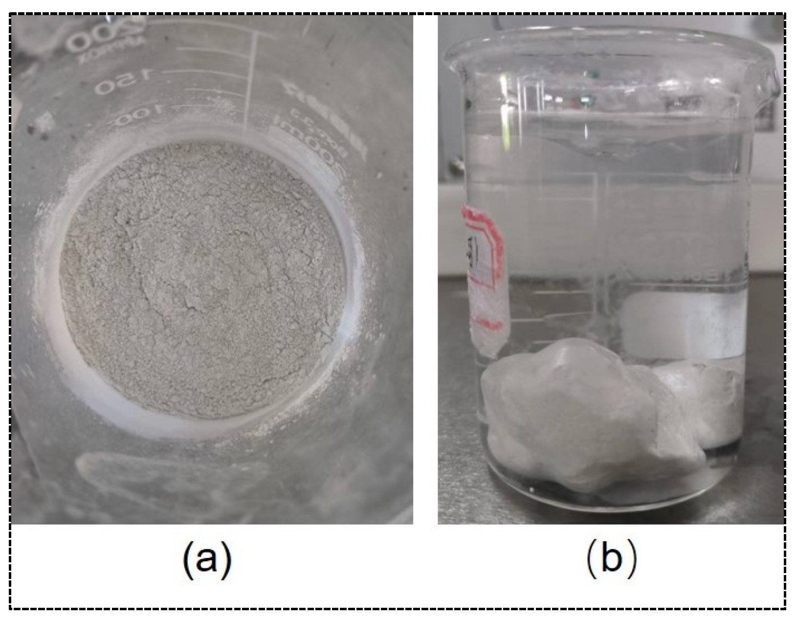
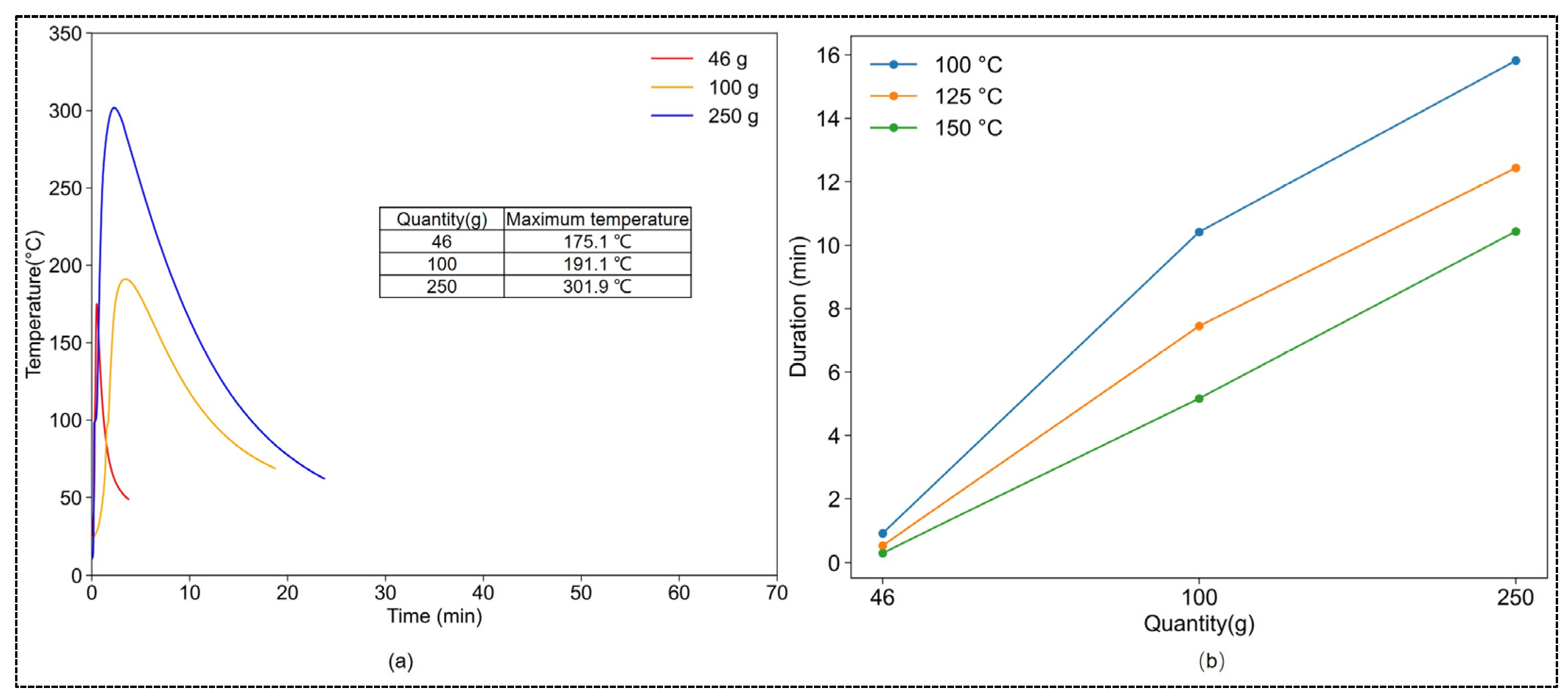
Hydration reactions are conducted using CaO-CM masses of 40 g, 100 g, 250 g, and 20 kg, respectively, under room temperature and standard atmospheric pressure.
The molar ratio of CaO-CM to water in all of the above reactions is 1:1. The experimental equipment mainly consists of four parts: reaction vessel (the parameters of the reaction vessel are shown in Table 1; there is insulation foam covering the outside during reacting), nitrogen tank, pressurization device, and temperature measurement device (as shown in Figure 4).
The specific experimental procedure is as follows: First, place the CaO-CM sample at the bottom of the reaction vessel, add distilled water to the top of the reaction vessel (with a container for storage), and then use the pressure pump to inject high-pressure nitrogen into the reaction vessel (the pressure can be adjusted by the pressure control valve according to the experimental requirements). After the injection of high-pressure nitrogen is completed, turn on the temperature measurement device and tilt the reaction vessel to allow the water stored in the upper part to react with the CaO-CM. After the experiment is completed, the high-pressure nitrogen in the reaction vessel can be released through the control valve.

2.3. Pyrolysis Experiment of Oil Shale Based on CaO-CM Hydration Reaction

The oil shale sample used is still Xinjiang oil shale. The specific experimental procedure is as follows: First, the oil shale is ground into powder (particle size less than 30 mesh). A total of 2 g of oil shale powder is placed into the copper tube with an inner diameter of 12.7 mm, wall thickness of 0.7 mm, and length of 4 cm. Both ends of the copper tube are sealed by underwater welding. A total of 250 g of CaO-CM is placed in the reaction vessel, and the sealed copper tubes are placed into the CaO-CM. The pressure inside the reaction vessel is set to 0.1 MPa, 5 MPa, and 10 Mpa, respectively. Each experiment uses one copper tube sample, with a total of three copper tube samples being used. Another copper tube sample is placed into a muffle furnace for pyrolysis, with the pyrolysis temperature set at 450 °C for 3 h. After the experiment is completed, the copper tube is removed, and 100 mg of the oil shale powder inside the copper tube is placed into the pyrolysis gas chromatograph to measure the content of pyrolysis hydrocarbons. A comparative analysis of the change in pyrolysis hydrocarbon content before and after oil shale pyrolysis is conducted. The experimental procedure is depicted in Figure 5.

3. Results and Discussion

3.1. Determination of the Oil Shale Pyrolysis Temperature

According to the study by Zhao et al. [33], oil production was observed only when the temperature of oil shale pyrolysis reached 300 °C or higher, and the presence of yellow liquid can be used as an indicator of oil production. Therefore, in this experiment, the muffle furnace temperature was set as follows: the first stage was the heating stage, during which the temperature was uniformly raised from room temperature to 400 °C over 30 min; the second stage was the constant temperature stage, maintaining the temperature at 400 °C for 130 min; and the third stage was the cooling stage, during which the temperature was reduced from 400 °C to 100 °C over 50 min.
The experimental results, as shown in Figure 6, reveal a certain temperature difference between the reaction vessel and the muffle furnace due to the process of heat conduction from the furnace to the reaction vessel. The temperature curve inside the reaction vessel is represented by the black line in the graph. When the experiment reached 62 min, the temperature inside the reaction vessel reached 300 °C, with no noticeable liquid flow observed in the conduit. Upon weighing the condensation collection device, it was found to have collected 1 g of colorless and odorless product (since the temperature of the condensation collection device was set to −20 °C, the product inside the device was solid), which was later determined to be water. When the experiment reached 77 min, the temperature inside the reaction vessel reached 330 °C, and yellow liquid (oil) began to flow into the condensation collection device through the conduit. When the experiment reached 126 min, the temperature inside the reaction vessel reached 400 °C, at which point the condensation collection device collected a total of 2 g of the oil–water mixture. Between 126 and 160 min into the experiment, the temperature inside the reaction vessel slightly exceeded that of the muffle furnace, which is attributed to the temperature measurement accuracy of the two devices. During this period of the experiment, a significant amount of yellow liquid (oil) flow was observed in the conduit. By the 160 min mark, a total of 6 g of oil–water mixture had been collected in the condensation collection device. From 160 to 210 min, the experiment entered the cooling stage, during which yellow liquid continued to be produced. By the end of the 210 min mark, a total of 7 g of oil–water mixture had been collected.
Based on the experimental process and observations above, it is evident that when the pyrolysis temperature of Xinjiang oil shale is below 330 °C, only water is produced without any oil. Oil production begins when the pyrolysis temperature of oil shale reaches 330 °C, and a significant amount of oil is produced when it reaches 400 °C. Therefore, the minimum temperature for oil production during the pyrolysis of Xinjiang oil shale is 330 °C, with better pyrolysis efficiency observed at 400 °C compared to 330 °C.

3.2. The Temperature Properties of CaO-CM Hydration Reaction

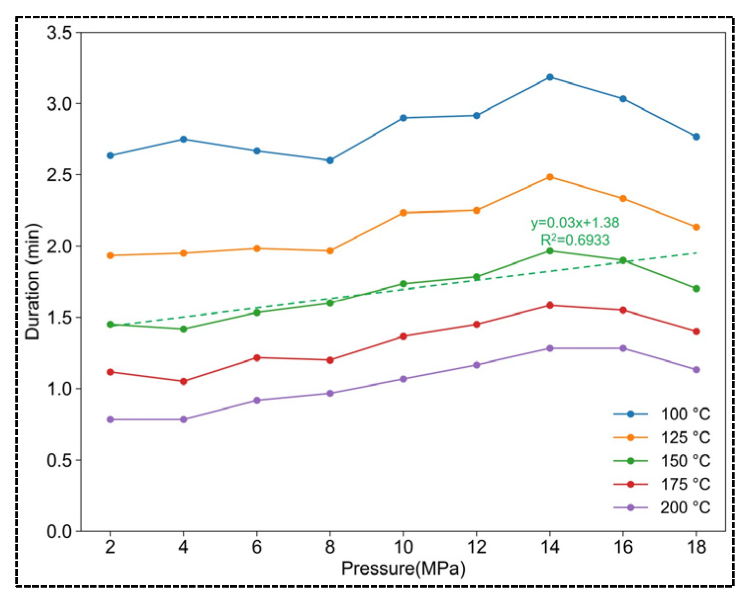
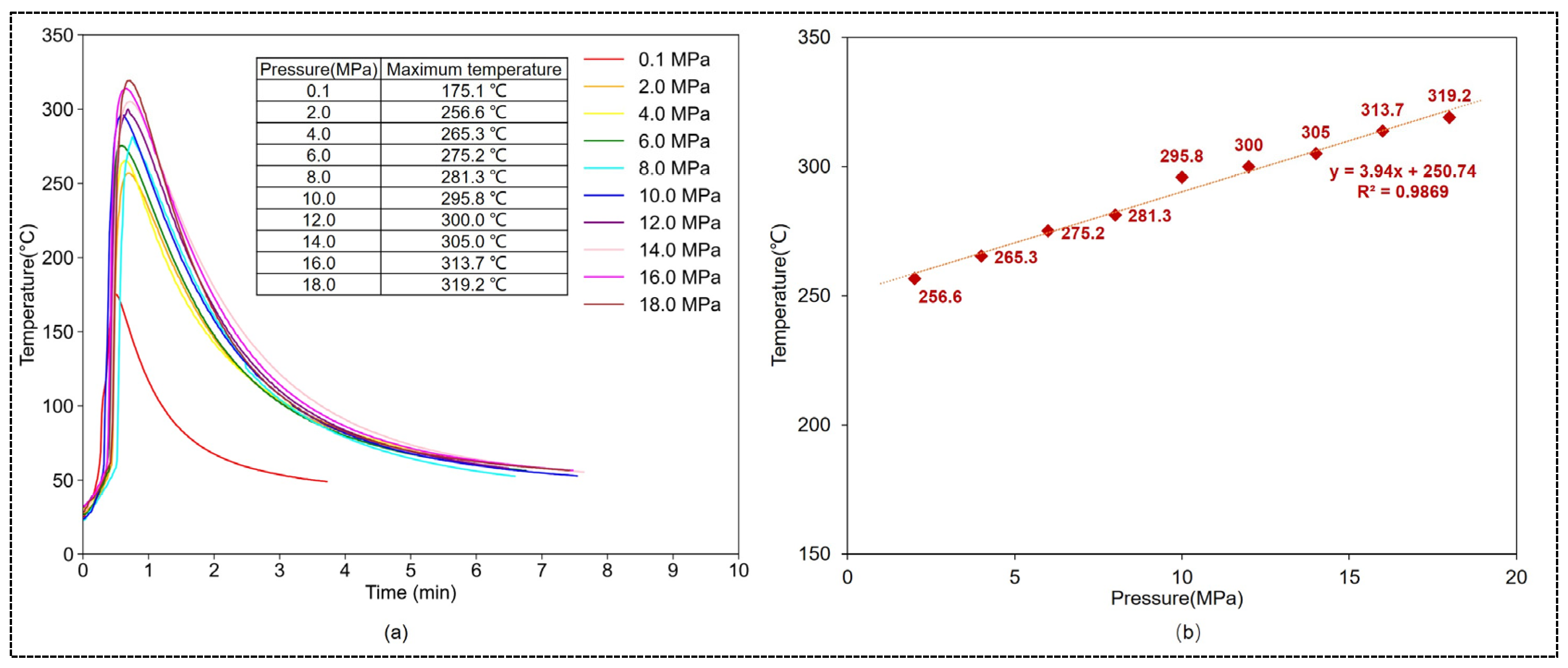
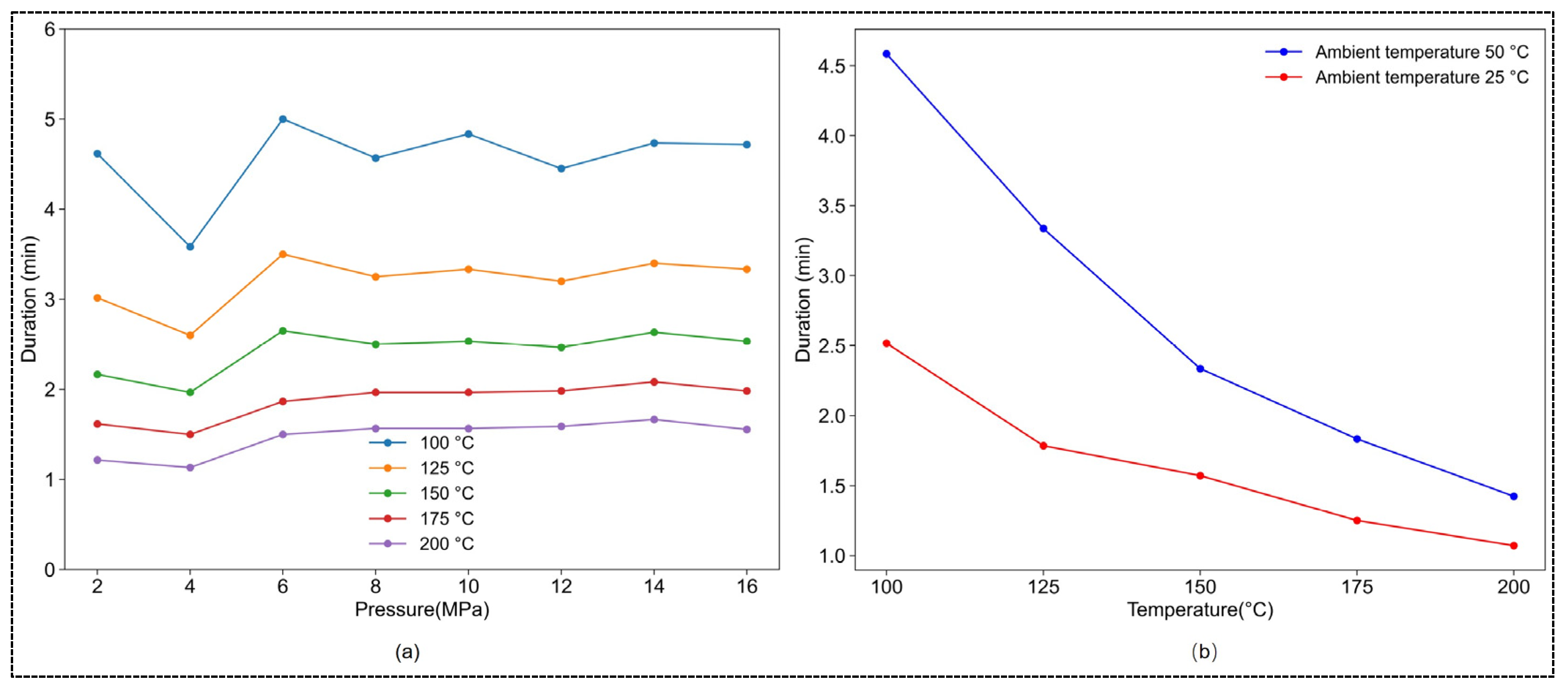
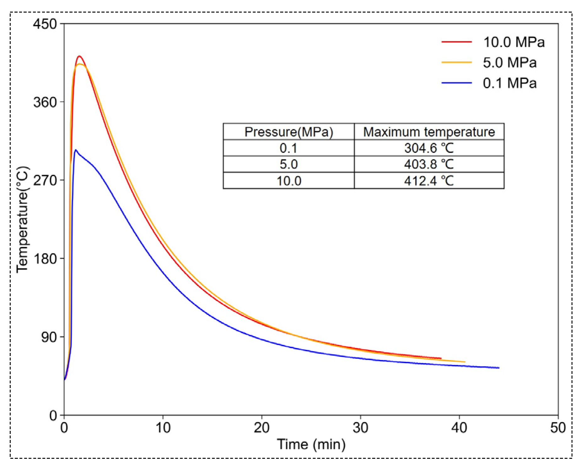
3.2.1. The Impact of Pressure on the Temperature of CaO-CM Hydration Reaction

(1)
The effect of pressure on the maximum temperature
The mass of CaO-CM used in this experiment was 46 g (limited by the capacity of the reaction vessel). The time–temperature curve for the hydration reaction of CaO-CM under different pressures is shown in Figure 7a, and the maximum temperatures achievable under different pressures are depicted in Figure 7b. From the graph, it is evident that under room temperature and standard atmospheric pressure, the maximum temperature achievable in the hydration reaction of CaO-CM is 175.1 °C. As environmental pressure increases, the maximum temperature attainable by the reaction also rises. The relationship between temperature and pressure is T = 3.94 P + 250.74 , where the correlation coefficient is 0.9869. Under the pressure of 18 MPa, the highest temperature can reach 319.2 °C. The entire process of the CaO-CM hydration reaction lasts approximately 8 min.
(2)
The effect of pressure on the duration of temperature
To explore the influence of pressure on the duration of temperature sustained during the hydration reaction of CaO-CM, the durations of the hydration reaction at temperatures above 100 °C, 125 °C, 150 °C, 175 °C, and 200 °C were recorded. As shown in Figure 8, the duration of temperature increases with the increase in reaction pressure, reaching its peak at 14 MPa. There is a decreasing trend in the temperature duration when the pressure exceeds 14 MPa. Taking the duration above 150 °C as an example, the fitted function relating duration to pressure is t = 0.03 P + 1.38 , with a correlation coefficient of 0.6933. From this, it can be inferred that pressure has a relatively minor effect on the duration of the reaction temperature of CaO-CM.

3.2.2. The Impact of Environmental Temperature on the Hydration Reaction Temperature of CaO-CM

(1)
The effect of environmental temperature on the maximum temperature
The time–temperature curve of the hydration reaction of CaO-CM under the environmental temperature of 50 °C is depicted in Figure 9a. The relationship between maximum temperature and pressure is illustrated in Figure 9b. The maximum temperatures achievable by the hydration reaction of CaO-CM under environmental temperatures of 25 °C and 50 °C are illustrated in Figure 9c. From Figure 9a,b, it can be observed that at the environmental temperature of 50 °C and standard atmospheric pressure, the hydration reaction of CaO-CM can reach a maximum temperature of 185 °C. As pressure increases, the maximum temperature attainable by the reaction also rises, reaching a maximum temperature of 331.5 °C with a pressure of 16 MPa. The relationship between temperature and pressure is T = 4.81 P + 263.2 , where the correlation coefficient is 0.9183. The entire process of the CaO-CM hydration reaction lasts approximately 11 min. From Figure 9c, under the same reaction pressure, a higher ambient temperature allows for a higher maximum temperature to be reached. From Figure 9d, compared to an ambient temperature of 25 °C, the highest temperature increases by 10.3 to 27.7 °C when the ambient temperature is 50 °C.
(2)
The effect of ambient temperature on the duration of temperature
As shown in Figure 10a, the durations of the hydration reaction at temperatures above 100 °C, 125 °C, 150 °C, 175 °C, and 200 °C were recorded. Overall, with increasing pressure, there is a slight increase in the duration of temperature, but it remains relatively stable. Figure 10b presents the average duration of temperature under different reaction pressures at ambient temperatures of 25 °C and 50 °C. It is evident from the graph that higher ambient temperatures lead to longer durations of temperature. At the ambient temperature of 50 °C, the duration above 100 °C is 1.61 times longer, above 125 °C is 1.5 times longer, above 150 °C is 1.45 times longer, above 175 °C is 1.41 times longer, and above 200 °C is 1.42 times longer than at 25 °C.

3.2.3. The Impact of the Quantity of CaO-CM Hydration Reaction Mass on the Reaction Temperature

The temperature–time curves of the hydration reaction of CaO-CM under different masses at room temperature and standard atmospheric pressure are illustrated in Figure 11a. From the graphs, it can be observed that when the mass of CaO-CM is 46 g, 100 g, and 250 g, the maximum temperatures are 175.1 °C, 191.1 °C, and 301.9 °C. The maximum temperature of the hydration reaction of CaO-CM increases with the increase in reaction mass, and the duration of the high-temperature phase is prolonged.
As shown in Figure 11b, as the mass of reactants increases, the duration of temperature sustenance significantly grows. Compared to 46 g, for CaO-CM weighing 100 g, the duration at temperatures above 100 °C is 11.36 times, above 125 °C is 13.97 times, and above 150 °C is 17.22 times.
From the above results, it can be observed that with an increase in the reaction mass, both the maximum temperature achievable and the duration of temperature increase. Therefore, to investigate whether the hydration reaction temperature of CaO-CM under room temperature and pressure can meet the temperature requirements for oil shale pyrolysis, experiments using 20 kg of CaO-CM for hydration were conducted. The experimental results are illustrated in Figure 12. From the graph, it can be seen that under ambient conditions, the hydration reaction of 20 kg of CaO-CM can achieve a maximum temperature of 455.5 °C. The duration of temperatures above 400 °C is 2.4 h, and above 330 °C is 4.06 h, fully meeting the temperature requirements for oil shale pyrolysis.

3.3. Thermal Decomposition Experiment of Oil Shale Based on CaO-CM Hydration Reaction

As revealed in Section 3.1 and Section 3.2.3, the temperature theoretically generated by the hydration reaction of CaO-CM meets the temperature requirements for the thermal decomposition of oil shale. But further experiments are needed to confirm that. The experimental procedure is described in Section 2.3. The experiment primarily aims to determine whether the temperature generated by the hydration reaction of CaO-CM can induce the pyrolysis hydrocarbon of CaO-CM by measuring the changes before and after oil shale pyrolysis. Copper tubes containing oil shale powder are, respectively, placed into CaO-CM inside reaction vessels with pressures of 0.1 MPa, 5 MPa, and 10 MPa. Another copper tube is placed in the muffle furnace for pyrolysis, with the temperature set to 450 °C and the duration to 3 h. The temperature–time curve of the hydration reaction of CaO-CM is shown in Figure 13. Under the pressure of 0.1 MPa, the highest temperature reached in the reaction is 304.6 °C. Under the pressure of 5 MPa, the highest temperature reached in the reaction is 403.8 °C, and under the pressure of 10 MPa, the highest temperature reached in the reaction is 412.4 °C. After the reaction is completed, the copper tube is removed, and the content of pyrolysis hydrocarbons inside the oil shale is measured. The results are presented in Table 2. The content of pyrolysis hydrocarbons before oil shale pyrolysis was 40.96 mg/g. After pyrolysis through the hydration reaction of CaO-CM under the pressure of 0.1 MPa, the content of pyrolysis hydrocarbons decreased to 40.60 mg/g. Under the pressure of 5 MPa, the content decreased to 0.88 mg/g, and under 10 MPa pressure, it decreased to 0.08 mg/g. The content of pyrolysis hydrocarbons after pyrolysis in the muffle furnace was 0.06 mg/g. Under pressure of 5 MPa and 10 MPa, the temperature generated by the hydration reaction of CaO-CM significantly reduced the amount of pyrolysis hydrocarbons in oil shale, with pyrolysis effectiveness comparable to that of the muffle furnace. This experiment demonstrates that the temperature provided by the hydration reaction of CaO-CM is sufficient to induce oil shale pyrolysis.

3.4. Discussion

Based on the experimental results, it can be concluded that the temperature required for oil production during the pyrolysis of Xinjiang oil shale is 330 °C, and a significant amount of oil is produced at a pyrolysis temperature of 400 °C. Therefore, the temperature conditions required for the pyrolysis of Xinjiang oil shale must reach above 330 °C. The temperature generated by the hydration reaction of CaO-CM is related to environmental pressure, environmental temperature, and the quantity of reaction. As environmental pressure, environmental temperature, and reaction quantity increase, the maximum temperature and the duration of temperature sustenance will also increase. This can be achieved by the hydration reaction of CaO-CM also increasing. For the influence on the maximum temperature achievable by the reaction, environmental temperature factors have a relatively minor impact, while pressure and the mass of reactants have a significant impact. As for the influence on the duration of temperature sustenance, pressure and temperature factors have a relatively minor impact, while the mass of reactants has a significant impact. Under room temperature and standard atmospheric pressure, when the mass of CaO-CM is 20 kg, the hydration reaction can achieve a maximum temperature of 455.5 °C, with a duration of 2.4 h above 400 °C, which fully meets the temperature requirements for the pyrolysis of Xinjiang oil shale. Experiments based on the hydration reaction of CaO-CM for oil shale pyrolysis demonstrated that the hydration reaction of CaO-CM can induce the pyrolysis hydrocarbons of oil shale. Due to experimental constraints, issues may arise during the experiment. The experimental system is open, leading to heat loss despite insulation foam covering the reaction vessel. Additionally, the demand for equipment materials in high-temperature, high-pressure environments is stringent, resulting in the manufacturing of reaction vessels with relatively small capacities; the amount of CaO-CM used in experiments under high-pressure conditions was limited to below 250 g. If the oil shale is directly placed into CaO-CM for experimentation, the pyrolysis products would mix with the generated calcium hydroxide, making it impossible to collect them. Therefore, the pyrolysis of oil shale is conducted by placing it into a copper tube, and measuring the changes in the content of pyrolysis hydrocarbons indirectly proves the feasibility of oil shale pyrolysis based on the hydration reaction of CaO-CM, but oil shale cannot be directly incorporated within CaO-CM, potentially leading to deviations between the observed reaction behavior and real-world field applications. In subsequent research, larger containers will be used to store the oil shale, and the pyrolysis products will be directly collected through a condensation collection device.
Due to experimental constraints, in actual scenarios, CaO-CM needs to directly contact the oil shale formation. Regarding how to achieve the reaction of CaO-CM within the reservoir, our preliminary proposal involves the following two steps: (1) Completion of horizontal well drilling: A drilling platform is established at the top of the reservoir, drilling operations are carried out, and vertical sections of the wellbore penetrate through overlying strata. Horizontal drilling operations are conducted within the shale oil and oil shale reservoirs, followed by well completion. (2) High-pressure hydraulic fracturing and CaO-CM injection: Intensive perforation or cutting is performed in the horizontal drilling section to fracture the shale oil and oil shale reservoirs. High-concentration CaO-CM powder and water are injected into the reservoirs, where CaO-CM reacts with water to generate calcium hydroxide, producing a large amount of heat. This raises the reservoir temperature, inducing the thermal decomposition of organic matter to produce oil and gas.

4. Conclusions

The proposal of the theory and method of in situ chemical thermogenesis for oil shale extraction offers a new pathway for the extraction of oil shale. However, there has been no investigation into the temperature-related properties of calcium-oxide-based composite material. Based on this, the paper conducted experiments to assess the feasibility of temperature associated with this material. The following conclusions have been drawn:
(1)
The minimum pyrolysis temperature of Xinjiang oil shale is 330 °C, with significant yields observed at a pyrolysis temperature of 400 °C.
(2)
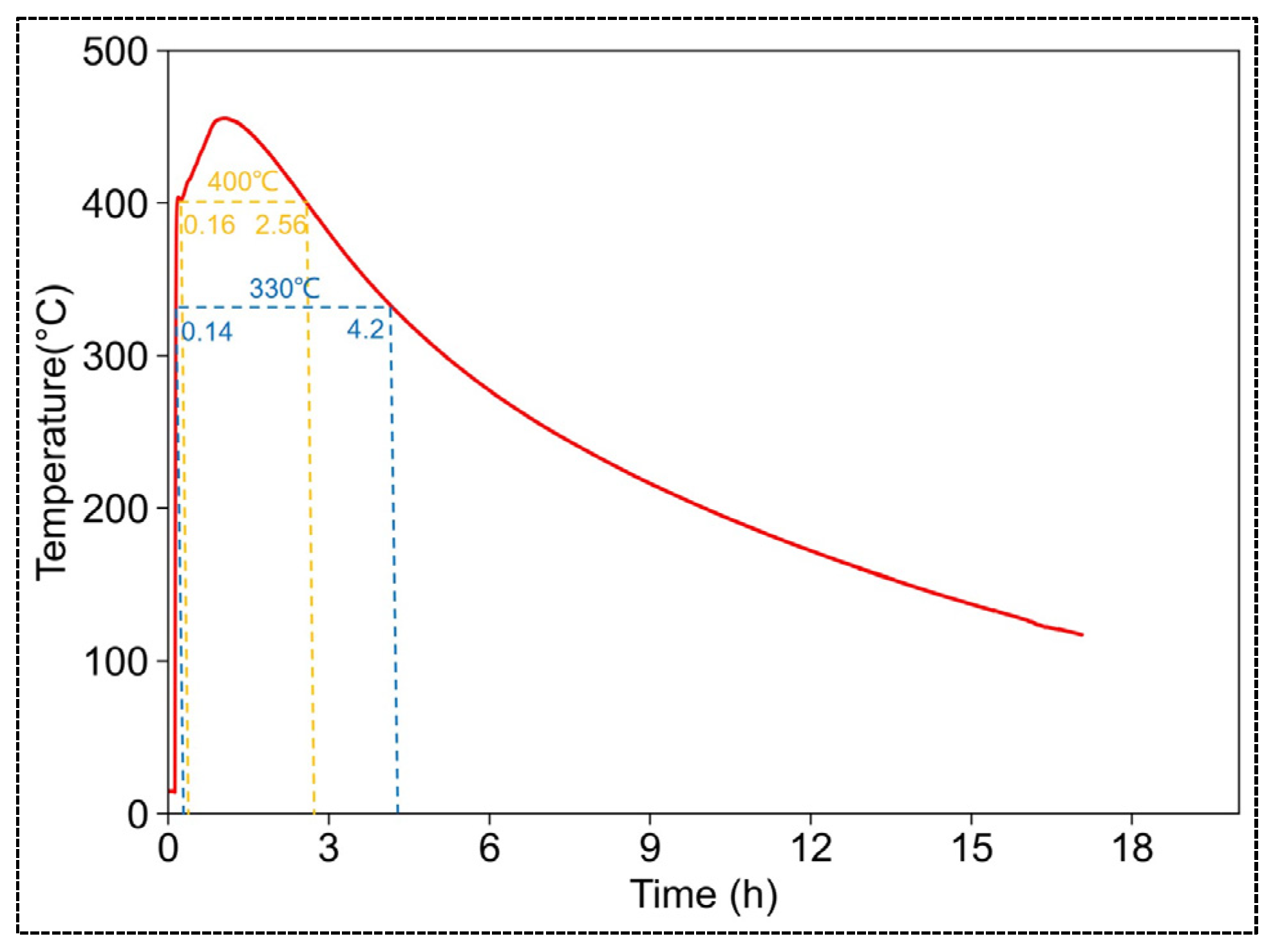
The temperature of the hydration reaction of CaO-CM is influenced by environmental temperature, pressure, and the quantity of reactants. For the influence on the maximum temperature achievable by the reaction, environmental temperature factors have a relatively minor impact, while pressure and the mass of reactants have a significant impact. As for the influence on the duration of temperature sustenance, pressure and temperature factors have a relatively minor impact, while the mass of reactants has a significant impact. When the mass of CaO-CM is 20 kg, the hydration reaction can reach a maximum temperature of 455.5 °C, sustaining temperatures above 400 °C for 2.4 h and above 330 °C for 4.06 h. The temperature conditions generated by the hydration reaction of CaO-CM meet the temperature requirements for oil shale pyrolysis.
(3)
Through an oil shale pyrolysis experiment based on the CaO-CM hydration reaction, it was found that there was a significant decrease in pyrolysis hydrocarbons after the experiments. This indicates that the temperature generated by the hydration reaction of CaO-CM induced the pyrolysis of organic matter in oil shale, ultimately resulting in a reduction in the pyrolysis hydrocarbon content in the oil shale. This finding substantiates the feasibility of oil shale pyrolysis based on the hydration reaction of CaO-CM.
Of course, the current validation experiments are only at the laboratory stage, and the feasibility study of this in situ conversion method based on CaO-CM for oil shale is just beginning. Subsequent research will continue with relevant validation experiments of, for example, how CaO-CM is injected into the oil shale reservoir, whether the injection quantity is controllable, the potential impact on the mechanical properties of the reservoir after injection, what composition of hydrocarbons are formed under these experimental conditions, how does their composition change when various parameters change, and the influence of varying CaO-CM-to-water molar ratios and the impact of diverse CaO-CM particle sizes on the reaction.

Author Contributions

Conceptualization, S.L.; Formal analysis, S.M.; Methodology, S.M.; Resources, G.L.; Supervision, S.L. and X.L.; Validation, S.M.; Visualization, B.Z. and Y.H.; Writing—original draft, S.M.; Writing—review and editing, Z.Z. and T.X. All authors have read and agreed to the published version of the manuscript.

Funding

This research was founded by the National Natural Science Foundation of China [Grant No. 42090023]; the Scientific Research and Technology Development Project of China National Petroleum Corporation [No. 2022DJ5503]; and the CAS Key Technology Talent Program.

Data Availability Statement

The data presented in this study are available on request from the corresponding author.

Acknowledgments

The authors would like to thank the Key Laboratory of Shale Gas and Geoengineering of the Institute of Geology and Geophysics of the Chinese Academy of Science, Beijing.

Conflicts of Interest

The authors declare no conflict of interest.

References

  1. Hou, L.; Luo, X.; Lin, S.; Li, Y.; Zhang, L.; Ma, W. Assessment of recoverable oil and gas resources by in-situ conversion of shale—Case study of extracting the Chang 73 shale in the Ordos Basin Petrol. Pet. Sci. 2022, 19, 441–458. [Google Scholar] [CrossRef]
  2. Jin, Z.; Bai, Z.; Gao, B.; Li, M. Has China ushered in the shale oil and gas revolution? Oil Gas Geol. 2019, 40, 451–458. (In Chinese) [Google Scholar] [CrossRef]
  3. Hu, S.; Zhao, W.; Hou, L.; Yang, Z.; Zhu, R.; Wu, S.; Bai, B.; Jin, X. Development potential and technical strategy of continental shale oil in China. Pet. Explor. Dev. 2020, 47, 819–828. [Google Scholar] [CrossRef]
  4. Zou, C.; Pan, S.; Jing, Z.; Gao, J.; Yang, Z.; Wu, S.; Zhao, Q. Shale oil and gas revolution and its impact. Acta Pet. Sin. 2020, 41, 1–12. (In Chinese) [Google Scholar] [CrossRef]
  5. Zhao, W.; Zhu, R.; Hu, S.; Hou, L.; Wu, S. Accumulation contribution differences between lacustrine organic-rich shales and mudstones and their significance in shale oil evaluation. Pet. Explor. Dev. 2020, 47, 1079–1089. [Google Scholar] [CrossRef]
  6. Aurela, M.; Mylläri, F.; Konist, A.; Saarikoski, S.; Olin, M.; Simonen, P.; Bloss, M.; Nešumajev, D.; Salo, L.; Maasikmets, M.; et al. Chemical and physical characterization of oil shale combustion emissions in Estonia Atmos. Atmos. Environ. 2021, 12, 100139. [Google Scholar]
  7. Kalu, I.E.; Jossou, E.; Arthur, E.K.; Ja’afaru, S.; Ishidi, E.Y. Characterization and Mechanical Property Measurements by Instrumented Indentation Testing of Niger Delta Oil Shale Cuttings. Int. J. Eng. Res. Afr. 2022, 59, 89–100. [Google Scholar] [CrossRef]
  8. Sun, Y.; Guo, W.; Deng, S. The status and development trend of in-situ conversion and drilling exploitation technology for oil shale. Drill. Eng. 2021, 48, 57–67. (In Chinese) [Google Scholar]
  9. Burwell, E.L.; Sterner, T.E.; Carpenter, H.C. Shale Oil Recovery by In-Situ Retorting—A Pilot Study. J. Pet. Technol. 1970, 22, 1520–1524. [Google Scholar] [CrossRef]
  10. Carpenter, H.C.; Burwell, E.L.; Sohns, H.W. Evaluation of an In-Situ Retorting Experiment in Green River Oil Shale. J. Pet. Technol. 1972, 24, 21–26. [Google Scholar] [CrossRef]
  11. Miller, J.S.; Howell, W.D. Explosive fracturing tested in oil shale. Colo. Sch. Min. Q. 1967, 62, 63–73. [Google Scholar]
  12. Ryan, R.C.; Fowler, T.D.; Beer, G.L.; Nair, V. Oil Shale: A Solution to the Liquid Fuel Dilemma; ACS Publications: Washington, DC, USA, 2010; pp. 161–183. [Google Scholar]
  13. Yang, H.; Gao, X.; Xiong, f.; Zhang, J.; Li, Y. Temperature distribution simulation and optimization design of electric heater for in-situ oil shale heating. Oil Shale 2014, 31, 105. [Google Scholar]
  14. Vinegar, H. Shell’s in-situ conversion process. In Proceedings of the 26th Oil Shale Symposium, Golden, CO, USA, 16–20 October 2006. [Google Scholar]
  15. Bunger, J.W.; Crawford, P.M.; Johnson, H.R. Is oil shale America’s answer to peak-oil challenge? Oil Gas J. 2004, 8, 16–24. [Google Scholar]
  16. Tanaka, P.L.; Yeakel, J.D.; Symington, W.A.; Spiecker, P.M.; Del Pico, M.; Thomas, M.M.; Sullivan, K.B.; Stone, M.T. Plan to test ExxonMobil’s in situ oil shale technology on a proposed RD&D lease. In Proceedings of the 31st Annual Oil Shale Symposium, Golden, CO, USA, 17–21 October 2011. [Google Scholar]
  17. Melton, N.M.; Cross, T.S. Fracturing Oil Shale with Electricity. J. Pet. Technol. 1968, 20, 37–41. [Google Scholar] [CrossRef]
  18. Grant, B.F. Retorting oil shale underground—Problems and possibilities. Q. Colo. Sch. Mines 1964, 59, 39–46. [Google Scholar]
  19. Knaus, E.; Killen, J.; Biglarbigi, K.; Crawford, P. An overview of oil shale resources. Oil Shale Solut. Liq. Fuel Dilemma 2010, 1032, 3–20. [Google Scholar]
  20. Boak, J. Oil Shale: Is Now the Time? Garfield County Energy Advisory Board: Denver, CO, USA, 2011. [Google Scholar]
  21. Crawford, P.M.; Killen, J.C. Oil Shale: A Solution to the Liquid Fuel Dilemma; ACS Publications: Washington, DC, USA, 2010; pp. 21–60. [Google Scholar]
  22. Jaber, J.O.; Probert, S.D. Non-isothermal thermogravimetry and decomposition kinetics of two Jordanian oil shales under different processing conditions. Fuel Process. Technol. 2000, 63, 57–70. [Google Scholar] [CrossRef]
  23. Crawford, P.M.; Biglarbigi, K.; Dammer, A.R.; Knaus, E. Advances in world oil shale production technologies. In Proceedings of the SPE Annual Technical Conference and Exhibition, Denver, CO, USA, 21–24 September 2008. [Google Scholar]
  24. Allix, P.; Burnham, A.; Fowler, T.; Herron, M.; Kleinberg, R.; Symington, B. Coaxing oil from shale. Oilfield Rev. 2010, 22, 4–15. [Google Scholar]
  25. Sun, Y.; Deng, S.; Wang, H. Advances in the exploitation technologies and researches of oil shale in the world: Report on 33rd oil shale symposium in US. J. Jilin Univ. (Earth Sci. Ed.) 2015, 4, 1052–1059. (In Chinese) [Google Scholar] [CrossRef]
  26. Wang, Y.; Wang, Y.; Meng, X.; Su, J.; Li, Z. Enlinhtenment of American’s oil shale in-suit retorting technology. Oil Drill. Prod. Technol. 2013, 35, 55–59. (In Chinese) [Google Scholar] [CrossRef]
  27. Kang, Z.; Zhao, Y.; Yang, D. Review of oil shale in-situ conversion technology. Appl. Energy 2020, 269, 115121. [Google Scholar] [CrossRef]
  28. Wang, H.; Deng, S.; Li, J. A Method for the In-Situ Extraction of Hydrocarbon Compounds from Oil Shale. CN101871339A, 15 May 2020. [Google Scholar]
  29. States United Congress. Office of Technology Assessment. An Assessment of Oil Shale Technologies; Congress, Office of Technology Assessment: Washington, DC, USA, 1980.
  30. Bai, F. Theoretical and Laboratory Study of Localized Chemical Method for Pyrolysis of Oil Shale. Doctoral Thesis, Jilin University, Changchun, China, 2015. [Google Scholar]
  31. Zhu, J.; Yang, Z.; Li, X.; Qi, S.; Jia, M. Application of microwave heating with iron oxide nanoparticles in the in-situ exploitation of oil shale. Energy Sci. Eng. 2018, 6, 548–562. [Google Scholar] [CrossRef]
  32. Li, S.; Li, X.; Wang, J.; Ma, S.; Sun, Y. Theory and method of in situ conversion of shale oil by chemical thermal. J. Eng. Geol. 2022, 30, 127–143. (In Chinese) [Google Scholar] [CrossRef]
  33. Zhao, J.; Wang, L.; Yang, D.; Kang, Z. Characteristics of oil and gas production of oil shale pyrolysis by water vapor injection. Oil Shale 2022, 39, 153–168. [Google Scholar]
Figure 1. The calcium-oxide-based composite material sample: (a) the sample in natural form; (b) the sample in water.
Energies 17 01798 g001
Figure 2. Experimental design and objectives.
Energies 17 01798 g002
Figure 3. Oil shale pyrolysis experimental procedure diagram.
Energies 17 01798 g003
Figure 4. Schematic diagram of experimental equipment.
Energies 17 01798 g004
Figure 5. Experimental procedure diagram.
Energies 17 01798 g005
Figure 6. Experimental process and phenomena.
Energies 17 01798 g006
Figure 7. The relationship between pressure and temperature: (a) time–temperature curves of different pressures; (b) the maximum temperature of different pressures.
Energies 17 01798 g007
Figure 8. The duration of temperature under different pressures.
Energies 17 01798 g008
Figure 9. The effect of ambient temperature on the maximum temperature and duration time: (a) time–temperature curves of different pressures; (b) the maximum temperature of different pressures; (c) the maximum temperature of 50 °C and 25 °C ambient temperatures; (d) the maximum temperature discrepancy of 50 °C and 25 °C ambient temperatures.
Energies 17 01798 g009
Figure 10. The duration of the temperature of the hydration reaction: (a) with environmental temperatures of 50 °C; (b) comparison between ambient temperatures of 25 °C and 50 °C.
Energies 17 01798 g010
Figure 11. The effect of reactant mass on the maximum temperature and duration time: (a) time-temperature curve; (b) the duration of temperature under different reaction masses.
Energies 17 01798 g011
Figure 12. Time–temperature curves of CaO-CM hydration reaction for masses of 20 kg.
Energies 17 01798 g012
Figure 13. The hydration reaction temperature–time curve of CaO-CM.
Energies 17 01798 g013
Table 1. The equipment parameters.
Muffle FurnaceReaction VesselCondensation Collection Device
BrandShang hai Sager (Shanghai Sager Furnace Co., Limited; Shanghai, China)MaterialGH4132BrandZhongke Refrigeration (Tianjin Zhongke Electronic Refrigeration Co., Ltd.; Tianjin, China)
ModelSG-XS-1700-3Maximum Pressure Resistance50 MPaModelNGB2-1
Set maximum Temperature1700 °CMaximum Temperature Resistance600 °CTemperature Control RangeRoom temperature to −50°
Furnace chamber Dimensions300 × 300 × 300 mmCapacity100 mLTemperature Control Accuracy0.5 °C
Temperature control Accuracy±1 °CInternal Diameter7.2 cmCollection Container Volume400 mL
Heating elementMolybdenum disilicide rodInternal Height4.2 cm--
Heating rate ranging0~30 °C/min----
Furnace chamber materialLightweight alumina ceramic fiber----
Table 2. Pyrolysis hydrocarbon content of oil shale before and after pyrolysis.
The Initial Oil ShaleAfter Hydration Reaction (Pressure)After Pyrolysis in the Muffle Furnace
0.1 MPa5 MPa10 MPa
The content of pyrolysis hydrocarbons (mg/g)40.9640.60.880.080.06
Disclaimer/Publisher’s Note: The statements, opinions and data contained in all publications are solely those of the individual author(s) and contributor(s) and not of MDPI and/or the editor(s). MDPI and/or the editor(s) disclaim responsibility for any injury to people or property resulting from any ideas, methods, instructions or products referred to in the content.

