Article

Non-Weighted Two-Stage Model Predictive Control Strategy Based on Three-Level NPC Inverter

School of Electrical Engineering and Automation, Jiangsu Normal University, Xuzhou 221000, China
*
Author to whom correspondence should be addressed.
Energies 2024, 17(8), 1813; https://doi.org/10.3390/en17081813
Submission received: 16 February 2024 / Revised: 2 April 2024 / Accepted: 6 April 2024 / Published: 10 April 2024

Abstract

:
This paper investigates the asynchronous motors driven by a Three-Level Neutral-Point-Clamped Voltage Source Inverter (3L-NPC-VSI) and aims to achieve control without weight factors and reduce torque ripple. It puts forward a non-weighted two-stage Finite-Control-Set Model Predictive Control (FCS-MPC) strategy. First, a hierarchical optimization method is adopted to address the difficulty of setting weight factors in traditional FCS-MPC applications. The method offers stratified designs of three performance indices, voltage jump, common-mode voltage, and current tracking, obviating the need for weight factor setting and reducing the calculation load of predictions. Secondly, to further mitigate torque ripple, an optimal vector or vector combination is implemented at the current control layer by adhering to the principle of minimal current tracking error. During the selection of the optimal vector combination, the first vector of the combination is chosen to be the vector at the end of the present cycle. This ensures that there is at most one switch within each control period, reducing the switching losses of the two-stage FCS-MPC. Lastly, detailed simulation and experimental analyses are conducted to verify the feasibility and effectiveness of the proposed strategy.

1. Introduction

Finite-Control-Set Model Predictive Control (FCS-MPC) can take full advantage of the discretization of inverters and is characterized by visual modeling and simple control structures. It can handle multiple objectives of the controlled subject and realize nonlinear optimization [1], showing huge potential in improving the static and dynamic performance of electrical drive systems [2]. However, traditional FCS-MPC still has difficulties in the setting of weight factors and confronts issues of excessive torque ripple in applications [3,4].
It is hard for the linear weighted sum method to achieve balanced optimization of performance indices due to the difficulty in the weight factor setting. In response to this challenge, scholars at home and abroad have put forward numerous solutions. To eliminate the influence of weight factors, the torque error and stator flux linkage error are normalized, and, based on this normalization, a cost function is designed [5]. However, the calculations of normalization are quite complicated. Reference [6] replaces the traditional torque and flux error cost functions of MPTC with a voltage vector tracking error evaluation function, which eliminates the weight factors of the stator flux. Reference [7] proposes a weightless factor model predictive control strategy, which designs and evaluates the three evaluation functions of capacitor voltage balance, power error, and switching frequency based on the idea of hierarchical evaluation function. Reference [8] proposes a weightless factor control strategy, which uses a layered method to control the voltage balance of the current and midpoint on the DC side, so as to avoid the weighting factor tuning process. Based on sorting, logical operation, and other methods, it is beneficial to solve the problem of difficult weight factor tuning; however, the implementation process of logical judgment is complicated. Reference [9] proposes a parallel prediction torque control of an induction motor without weight factor, which sets the constraint boundary for the torque and flux prediction value, and selects the optimal vector by using the self-selection mechanism. Reference [10] proposes a weightless factor model predictive control of a Z-source inverter based on a logic operation and sets two types of modules: control logic and judgment logic. The above two methods avoid the weight factor tuning process by converting the indicator tracking error but cannot quantitatively control each optimization index.
The above-mentioned literature constitutes extensive research on the weight factor setting and provides some practical solutions. But these solutions fail to take into account other performance indicators and encounter challenges in their application.
In order to solve the problem of excessive common-mode voltage, ref. [11] proposes an improved modulation mod for a non-isolated-series simultaneous-power-supply-type dual-input inverter with low common-mode current for new energy generation applications. This modulation technique aims to minimize voltage fluctuations across the parasitic capacitance during inverter mode transitions, thereby reducing common-mode currents. In order to reduce the common-mode voltage, in [12], the common-mode current path of the BDFG system is analyzed. At the same time, the common-mode voltage characteristics in Path 3 of the system are analyzed. The solution of carrier synchronization is given, and, at last, the common-mode current is suppressed.
Because the traditional single-vector FCS-MPC torque pulsation problem is large, domestic and foreign scholars proposed duty cycle FCS-MPC [13,14] and double-vector FCS-MPC [15,16,17].
The duty cycle FCS-MPC adjusts the output voltage vector amplitude by adjusting the active vector duty cycle, thus reducing the tracking error [13]. In order to reduce torque pulsation in permanent magnet synchronous motors, a duty cycle regulator is used in considering the effect of operating speed on the active voltage vector torque deviation [14], thus reducing torque pulsation. The duty cycle FCS-MPC second vector is fixed to the zero vector and can only adjust the magnitude of the output voltage vector; in this sense, no adjustment of the direction is possible.
The dual-vector FCS-MPC control strategy, which extends the second vector from the zero vector to all vectors, further improves the switching freedom and reduces torque pulsation [15]. The dual-vector model predictive current control strategy, based on generalized dual-vector FCS-MPC, considers the effect of action time to ensure the global optimum of the selected vectors and reduce current ripple [16], but the prediction process requires two traversals of all vectors and a large prediction calculation. Reference [17] proposes a generalized two-vector FCS-MPC to extend the second vector from the zero vector to any vector, and the strategy requires two pairs of combinations of all vectors per prediction cycle, and the prediction calculation amount is large. Reference [18] proposes a two-vector model to predict the current control method, which considers the influence of action time on control performance in the evaluation function, reduces the amount of prediction calculation, and improves static and dynamic performance. Reference [19] proposes an improved dual-vector model prediction current control strategy which considers the switching vector prediction error in the vector selection process, reduces the current harmonic content and torque ripple, and improves the system robustness. While duty cycle FCS-MPC and dual-vector FCS-MPC reduce torque pulsation to some extent, the fixed mode of vector action of these two strategies increases the switching frequency. Scholars have achieved switching frequency limitation mainly by adding a switching frequency constraint term to the evaluation function [20,21] and an adjacent vector selection method [22,23] in order to reduce the switching frequency. The low-switching-frequency control strategy proposed in the literature [20,21] reduces the number of switching operations by adding a switching frequency constraint to the evaluation function, but there is a problem with weight factor rectification. Reference [22] reduces the switching frequency by limiting the vector selection range of the prediction cycle to the adjacent vectors of the optimal vector of the previous cycle and reducing the number of switching states. The above literature effectively reduces the switching frequency, but the power switching device clamping approach for switching frequency constraint does not take into account other performance indicators, and also does not consider the system safety and stability issues, and the online rolling optimization approach increases the complexity and computational effort of the algorithm.
Based on the above research, this paper investigates the asynchronous motors driven by the 3L-NPC-VSI and proposes a non-weighted two-stage model predictive control method for a three-level inverter based on hierarchical optimization, which effectively avoids the setting of weight factors and reduces torque ripples. To minimize switching losses, the first vector in the optimal vector combination is selected as the vector at the end of the present period, ensuring that there is at most one switching transition per cycle. Finally, detailed simulation and experimental analyses are conducted for single-vector FCS-MPC, dual-vector FCS-MPC, and the proposed control strategy, verifying the feasibility and effectiveness of the proposed strategy.

2. System Modeling of Three-Level Inverter Finite-Control-Set Model Predictive Control

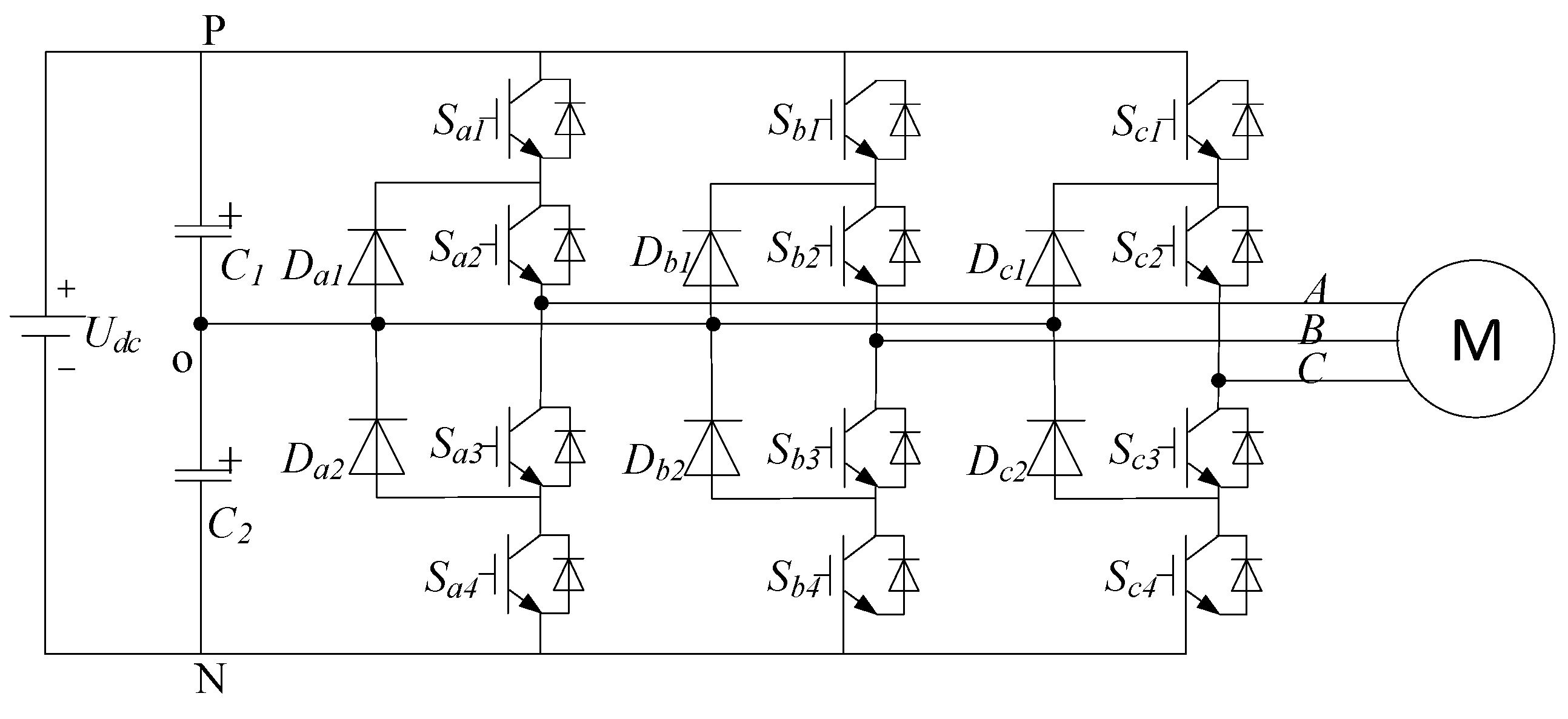
2.1. Three-Level Neutral-Point-Clamped Voltage Source Inverter Circuit Topology

Figure 1 presents the 3L-NPC-VSI topology.
During the normal operating state of a 3L-NPC-VSI, each phase outputs three electrical levels: Udc/2, 0, and −Udc/2, which are represented by P, O, and N, respectively. Udc denotes the DC bus voltage. The states of switches have a one-to-one correspondence with the output voltages. The switch state table of phase A is presented in Table 1.

2.2. Asynchronous Motor Prediction Model

Reference [23] offers the state equations of the mathematical model for a three-phase asynchronous motor with rotor flux orientation. These state equations are discretized with the Forward Euler method, which acquires the flux linkage and current prediction models.
ψ r d ( k + 1 ) = ( T s a 21 + 1 ) ψ r d ( k ) + T s a 22 i s d ( k )
i s d p ( k + 1 ) = ( 1 + T s a 32 ) i s d ( k ) + T s [ a 31 ψ r d ( k ) + a 33 i s q ( k ) + a 34 u s d ( k ) ] i s q p ( k + 1 ) = ( 1 + T s a 42 ) i s q ( k ) + T s [ a 41 ω ( k ) ψ r d ( k ) + a 43 i s d ( k ) + a 44 u s q ( k ) ]
Here, a21 = 1/τr, a22 = Lm/τr, a31 = Lm/σLsLrτr, a32 = a42 = (RsLr2 + RrLm2)/σLsLr2, a33 = ωe, a34 = a44 = 1/σLs, a41 = −npLm/σLsLr, a43 = −a33, σ = 1 − Lm2/LsLr, τr = Lr/Rr. In these formulas, Rs denotes the stator resistance, and Rr denotes the rotor resistance. Lr and Ls represent the stator and rotor inductances, respectively. Lm denotes the magnetizing inductance of the motor. The total leakage inductance is given by Lσ = σLs. ωe refers to the synchronous speed. ω refers to the rotor speed. ψr stands for the amplitude of the rotor flux linkage. Usd and Usq are the d-axis and q-axis components of the stator voltage, respectively. isd and isq are the d-axis and q-axis components of the stator current, respectively. ψrd is the d-axis component of the rotor flux linkage.
The prediction model suggests that the predicted current value at time k + 1 is drawn from the sample value of stator current isd(k)and flux linkage value ψrd(k) at the present moment. But when the optimal vector selected acts on the inverter at time k + 1, the sample current and flux linkage values will update to isd(k + 1) and ψrd(k + 1). Therefore, the control system always shows a one-step delay. To offset its effect, delay compensation is required.
Lagrange second-order extrapolation is applied to perform the delay compensation.
i * ( k + 1 ) = 3 i * ( k ) 3 i * ( k 1 ) + i * ( k 2 ) i * ( k + 2 ) = 3 i * ( k + 1 ) 3 i * ( k ) + i * ( k 1 )
where i*(k − 2), i*(k − 1), i*(k), i*(k + 1), i*(k + 2) represent corresponding given current values for times k − 2, k − 1, k, k + 1, k + 2, respectively.
Delay compensation first predicts isd(k + 1) and isq(k + 1) at time k + 1 as shown in Formulas (1) and (2). Then, it predicts isd(k + 2) and isq(k + 2) on the basis of predicted values at time k + 1.
i s d p ( k + 2 ) = ( 1 + T s a 32 ) i s d ( k + 1 ) + T s [ a 31 ψ r d ( k + 1 )             + a 33 i s q ( k + 1 ) + a 34 u s d ( k + 1 ) ] i s q p ( k + 2 ) = ( 1 + T s a 42 ) i s q ( k + 1 ) + T s [ a 41 ω ( k + 1 ) ψ r d ( k + 1 )             + a 43 i s d ( k + 1 ) + a 44 u s q ( k + 1 ) ] }
The switch states of the power converter can be represented by Sa, Sb, and Sc, respectively. The switch function is defined as follows, where x ∈ {a, b, c}:
S x ( k ) = { 1 S x 1 , S x 2 o p e n ,   S x 3 , S x 4 c l o s e 0 S x 2 , S x 3 o p e n ,   S x 1 , S x 4 c l o s e 1 S x 1 , S x 2 o p e n ,   S x 3 , S x 4 c l o s e
The stator voltage of the asynchronous motor in the d–q coordinate system is represented by the three-phase switch state function.
[ u s d ( k ) u s q ( k ) ] = 1 2 U d c C 3 / 2 [ S a ( k ) S b ( k ) S c ( k ) ]
Formula (7) presents the transformation matrix for converting the three-phase coordinate system to the two-phase rotating coordinate system, where θ refers to the rotor electrical angle, and ia, ib, ic represent the three-phase stator currents.
[ i d i q ] = 2 3 [ cos θ cos ( θ 2 3 π ) cos ( θ + 2 3 π ) sin θ sin ( θ 2 3 π ) sin ( θ + 2 3 π ) ] [ i a i b i c ]
The traditional FCS-MPC weighs three performance indicators through a linear weighting method. The evaluation function is shown as Formula (8).
g = | i * ( k + 2 ) i p ( k + 2 ) | + λ 1 u c o m
where i* (k + 2) and ip (k + 2) are the given values and predicted values of the torque component and excitation component of the stator current in the d–q coordinate system. λ1 denotes the weight factor, and ucom refers to the common-mode voltage.
Figure 2 displays the schematic diagram of the traditional FCS-MPC. As can be seen from the block diagram, the outer loop of the system is the speed loop, the actual value of the motor speed is obtained from the encoder, the difference is made with the reference value of the given speed, and the given value of the q-axis current is obtained through the PI controller. For asynchronous motors, the stator current can be measured directly. The rotor magnetic chain needs to use the magnetic chain observer to obtain, through the observation of the magnetic chain amplitude and the given value through the PI controller, the d-axis given current value. The sampled actual current and the given current value are passed through the model prediction controller, which outputs the optimal voltage vector corresponding to the inverter switching sequence, and realizes the control of the inverter on state.

3. Hierarchical-Optimization-Based Finite-Control-Set Model Predictive Control without Weight Factors

The hierarchical optimization method is employed to prioritize the three performance indicators of the 3L-NPC-VSI, which are voltage jump constraints, common-mode voltage rejection, and optimal control of current tracking error. This approach achieves the FCS-MPC controller design without weight factors and reduces computational load for predictions.

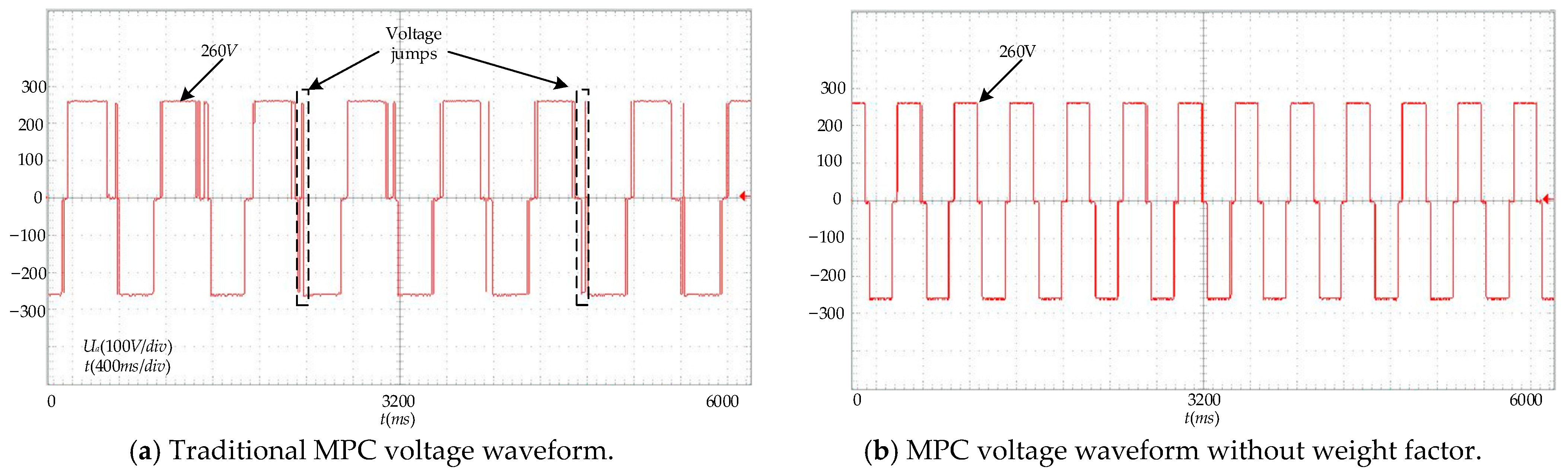
3.1. Voltage Jump Limits

An excessively high rate of voltage changes for 3L-NPC-VSI topology can damage motor insulation and even destroy switching devices, affecting the safe operation of the system. Therefore, each inverter switching action must ensure that both the output phase voltage and the line voltage do not exhibit jumps across two voltage levels. As it is a hard constraint, the voltage jump constraint is taken as the primary layer of optimization indices. Accordingly, the switch state transitions must ensure that the vectors in the next period are the present vector or its adjacent vectors. The vector at moment k is assumed to be S(k) = (Sa(k), Sb(k), Sc(k)). The possible optimization vectors for period k + 1 must satisfy the following constraints:
{ | S x ( k + 1 ) S x ( k ) | < 2 , x { a , b , c } | S a ( k + 1 ) S b ( k + 1 ) | < 2 | S b ( k + 1 ) S c ( k + 1 ) | < 2 | S c ( k + 1 ) S a ( k + 1 ) | < 2
The possible range for vector selection that satisfies the above constraints is as follows:
{ S ( k + 1 ) 1 = ( S a ( k ) S b ( k ) S c ( k ) ) S ( k + 1 ) 2 = ( S a ( k ) + 1 S b ( k ) S c ( k ) ) S ( k + 1 ) 3 = ( S a ( k ) 1 S b ( k ) S c ( k ) ) S ( k + 1 ) 4 = ( S a ( k ) S b ( k ) + 1 S c ( k ) ) S ( k + 1 ) 5 = ( S a ( k ) S b ( k ) 1 S c ( k ) ) S ( k + 1 ) 6 = ( S a ( k ) S b ( k ) S c ( k ) + 1 ) S ( k + 1 ) 7 = ( S a ( k ) S b ( k ) S c ( k ) 1 ) S ( k + 1 ) 8 = ( S a ( k ) + 1 S b ( k ) + 1 S c ( k ) ) S ( k + 1 ) 9 = ( S a ( k ) 1 S b ( k ) 1 S c ( k ) ) S ( k + 1 ) 10 = ( S a ( k ) + 1 S b ( k ) S c ( k ) + 1 ) S ( k + 1 ) 11 = ( S a ( k ) 1 S b ( k ) S c ( k ) 1 ) S ( k + 1 ) 12 = ( S a ( k ) S b ( k ) + 1 S c ( k ) + 1 ) S ( k + 1 ) 13 = ( S a ( k ) S b ( k ) 1 S c ( k ) 1 )

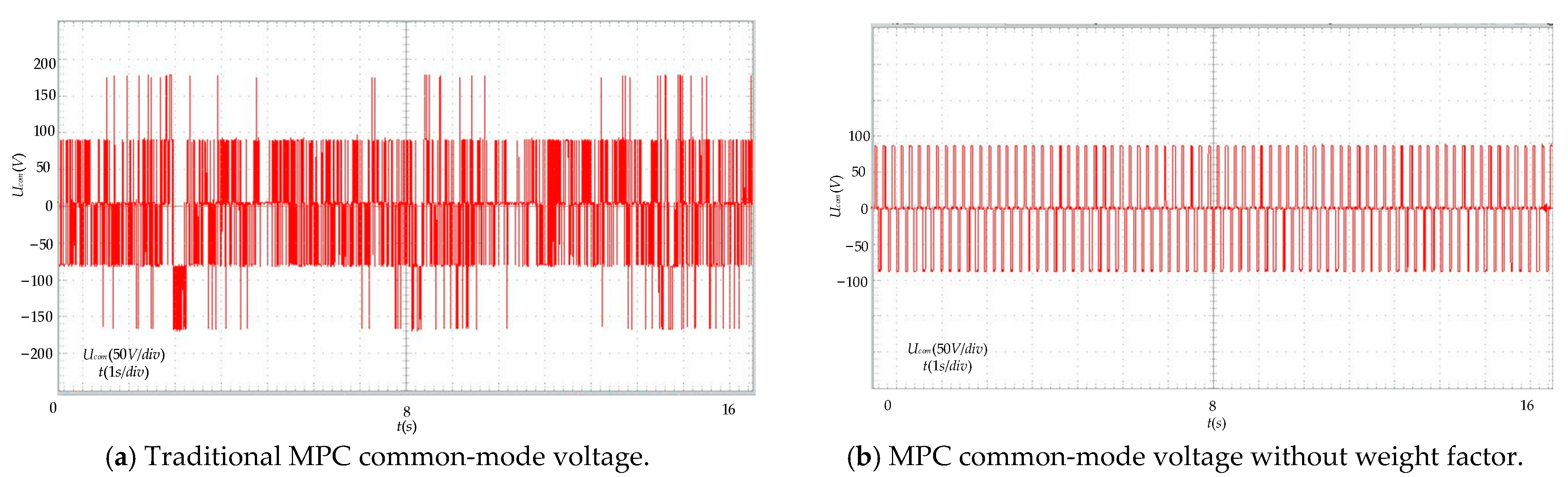
3.2. Common-Mode Voltage Rejection

Common-mode voltage refers to the voltage between the neutral point N and the reference point O of a three-phase load. Excessive common-mode voltage can lead to motor winding faults and bearing degradation. Therefore, it is necessary to reject common-mode voltage during optimization. Accordingly, the common-mode voltage rejection is treated as the second layer of optimization indices.
The common-mode voltage of the 3L-NPC-VSI is in a one-to-one correspondence with the switch states, as is shown in Table 2.
U c o m = V d c 6 ( S a ( k + 1 ) + S b ( k + 1 ) + S c ( k + 1 ) )
The 3L-NPC-VSI common-mode voltage has a one-to-one correspondence with the switching state, and the correspondence is shown in Table 2.
Table 2 indicates that the range of the common-mode voltage is [0, Udc/2]. A certain range of common-mode voltage is allowed in practical applications without affecting its performance. To ensure better dynamic performance for subsequent layers, the concept of “satisfactory” optimization is introduced to replace the optimization index, and a satisfactory interval is set to obtain satisfactory vectors. This paper limits the common-mode voltage to 1/6 of the DC side voltage. Therefore, the satisfactory interval is [−Udc/6, Udc/6]. The switching vectors that meet this criterion are determined by the magnitude of the common-mode voltage. The vectors for this layer are selected from all the vectors that satisfy the voltage jump constraint of the first layer.

3.3. Current Tracking Error

The current tracking error is the core of the stratified optimization control, which will not jeopardize the safe and stable operation of the control system. Therefore, it is taken as the third layer of optimization indicators.
The range of vectors selected for the minimum current tracking error includes all vectors that satisfy the common-mode voltage within the satisfactory interval. Predictive calculation of these vectors is conducted in the current optimal control layer. The evaluation function is shown in Formula (12).
g i = | i d * ( k + 2 ) i d p ( k + 2 ) | + | i q * ( k + 2 ) i q p ( k + 2 ) | ,
Here, i d * ( k + 2 ) and i q * ( k + 2 ) are the given current values. i d p ( k + 2 ) and i q p ( k + 2 ) are the predicted current values at the time k + 2.
Table 3 presents the performance index stratification based on the FCS-MPC strategy without weight factors for the 3L-NPC-VSI.

4. Improved Two-Stage Finite-Control-Set Model Predictive Control without Weight Factors

The hierarchical optimization approach is applied in the design of an FCS-MPC controller in a 3L-NPC-VSI system, which solves the challenge of setting the weight factors. However, in the third layer, the control of the current tracking error with a single vector might lead to excessive torque ripples in asynchronous motors. To address this issue, an improved two-stage FCS-MPC strategy is adopted at the current tracking error layer to further reduce torque ripples without increasing switching losses.

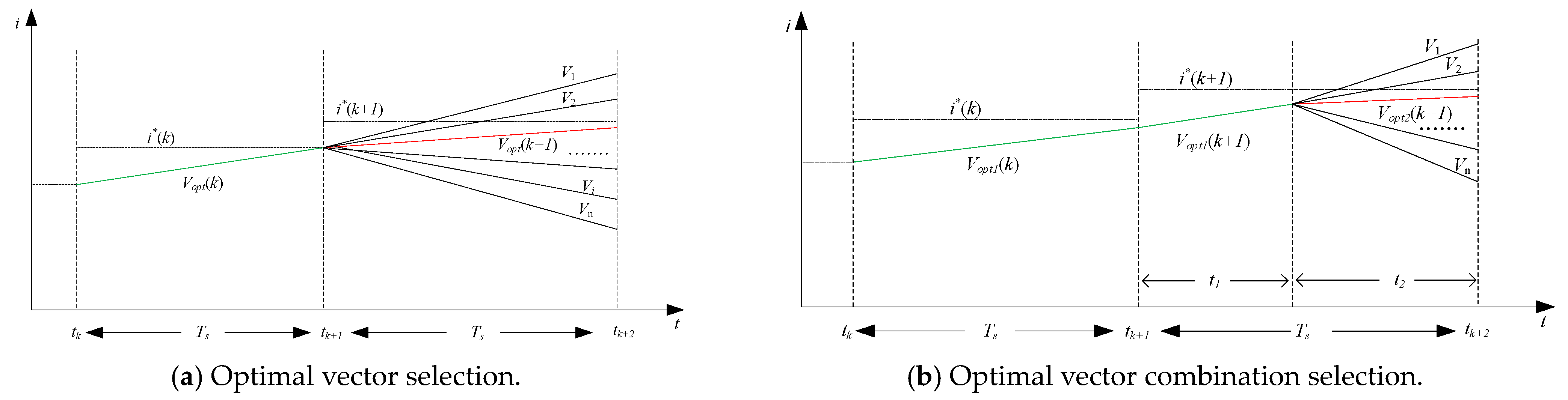
4.1. Vector Selection

The improved two-stage FCS-MPC strategy does not fix the number of vectors in each control period. Instead, it selects the optimal single vector or the optimal vector combination based on the principle of minimizing the current tracking error and then determines the final output vector. The vector selection in this strategy can be divided into three parts.
The first part is the selection of the optimal single vector. With the help of the exhaustive search optimization method, an optimal vector Vopt is selected through an evaluation function, and the action error is saved. The vector selection process is illustrated in Figure 3a. The optimal single vector is denoted as Vopt(k + 1), and its action error is denoted as g1min.
The second part involves the selection of the optimal vector combination. The first vector Vopt1 is chosen as the optimal vector of the previous cycle, which offers more accurate prediction for the current tracking control and avoids a switching transition. To decrease the computational load, the second vector is chosen from the vectors adjacent to the first vector. This method ensures that there is only one switching action within a control period during the application of the two-stage FCS-MPC, and reduces the strategy’s switching frequency. Therefore, during the optimal vector combination selection process of the improved two-stage FCS-MPC, the first switching vector is chosen as the vector at the end of the present cycle, ensuring that there is at most one switching action per cycle and achieving a dual-vector output without more switching losses. The vector selection process is depicted in Figure 3b. Vopt1(k + 1) and Vopt2(k + 1) refer to the optimal vector combination, and g2min denotes their action error.
The third part is the comparison of action errors. If g1min ≤ g2min, a single-vector action will be applied, and the optimal vector will be Vopt(k + 1). If g1min ≥ g2min, a dual-vector action will be taken, and the optimal vectors will be Vopt1(k + 1) and Vopt2(k + 1).
The improved two-stage FCS-MPC strategy integrates the advantages of traditional single-vector and dual-vector model prediction. It selects an optimal vector Vopt or an optimal vector combination Vopt1 and Vopt2 according to the principle of minimum action error for each control period. Figure 4 presents the vector function for this strategy. It is suggested that, within the [tk, tk+1] period, the single-vector action error is smaller than that of the vector combination, so the optimal single vector Vopt(k) is applied. During the [tk+1, tk+2] period, the single-vector action error is greater than that of the vector combination, so the optimal vector combination of Vopt1(k + 1) and Vopt2(k + 1) is applied.

4.2. Dwell Time Calculation

In the improved two-stage FCS-MPC strategy, when the optimal vector combination is applied, it is necessary to allocate the dwell time to the two voltage vectors. Dwell time is calculated based on the principle of the minimum error between reference values and predicted values in the FCS-MPC. This involves less dwell time for switching vectors with greater action errors to reduce the error. Therefore, it is considered that the action error caused by each switching vector is approximately in inverse proportion to the dwell time [24]. The calculation formula is as follows:
t 1 = g 2 g 1 + g 2 T s t 2 = g 1 g 1 + g 2 T s }
In this formula, g1 refers to the action error of the first vector Vopt1, and g2 refers to the action error of the second vector Vi to be evaluated.
During the application of the improved two-stage strategy, the pre-assigned dwell time for Vopt1 is denoted as t1. The predicted current values id(k + 2) and iq(k + 2) after Vopt1 action for time t1 are calculated through Formula (2). The pre-assigned dwell time for Vopt2 is denoted as t2. The predicted current values ip d(k + 2) and ip q(k + 2) at the time k + 2 are calculated with id(k + 2) and iq(k + 2) as the actual values. The results are inserted into Formula (12). The optimal vector or the optimal vector combination is selected through the action error comparison between the single-vector strategy and the improved two-stage strategy.

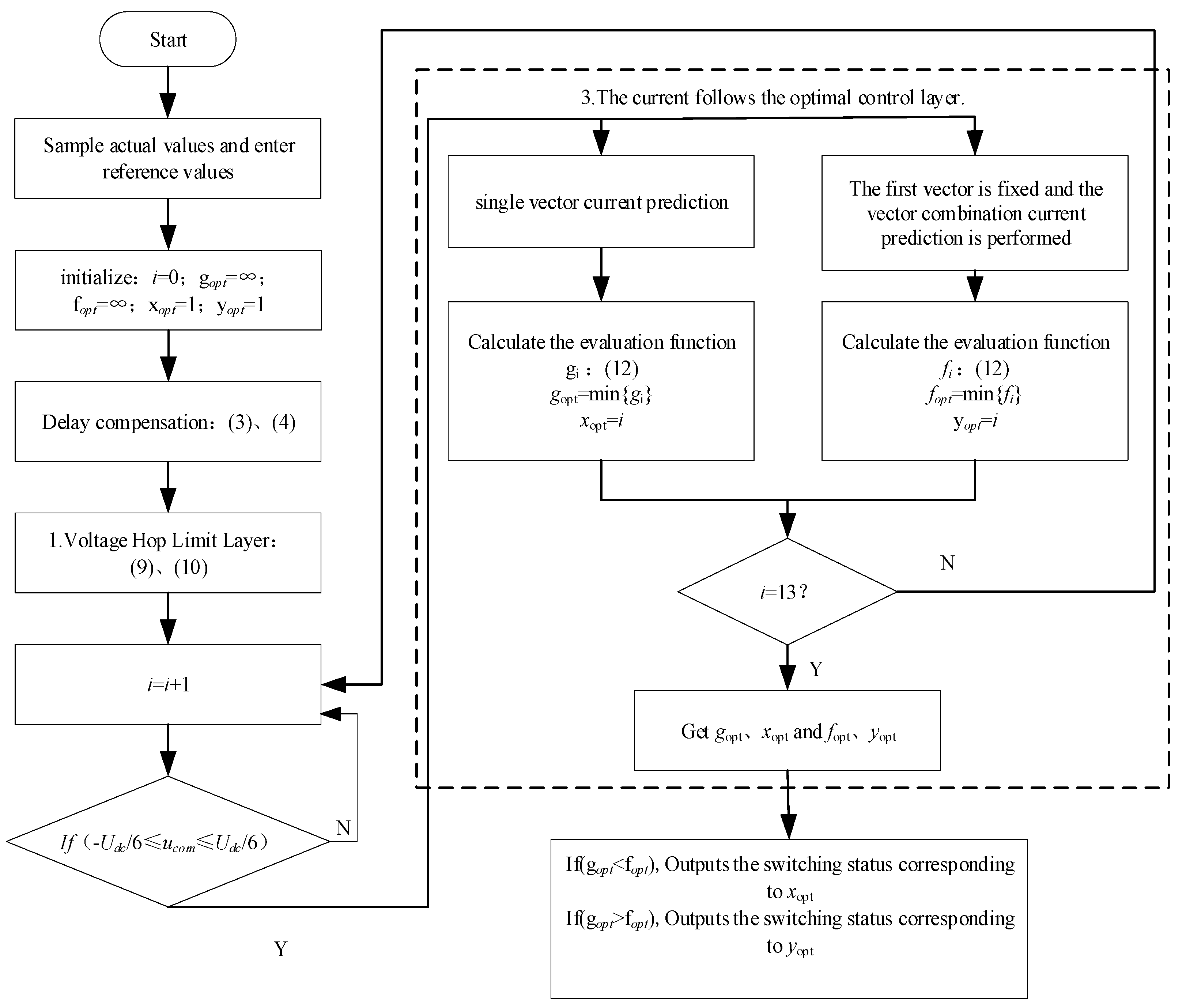
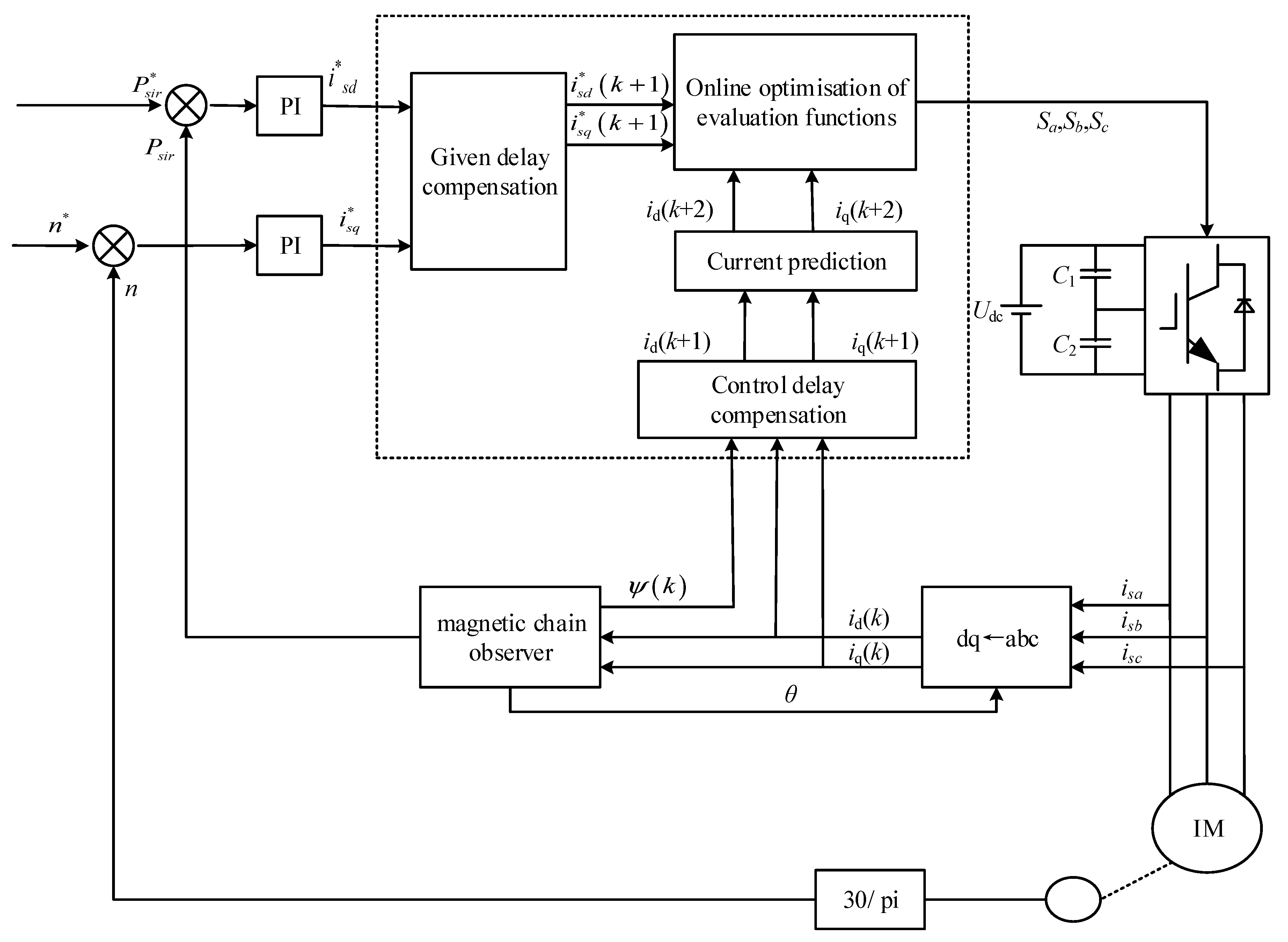
4.3. Improved Two-Stage Finite-Control-Set Model Predictive Control Strategy Flowchart

Figure 5 presents the flowchart of the improved two-stage FCS-MPC strategy proposed in this paper.
(1)
Sample actual values and input reference values for delay compensation;
(2)
Voltage jump limit: The limit on voltage jumps is achieved by selecting the vector adjacent to the action vector at the end of the present cycle;
(3)
Common-mode voltage rejection: Calculate the common-mode voltage and judge whether it falls within the satisfactory interval;
(4)
Optimal control of current tracking:
(4.1)
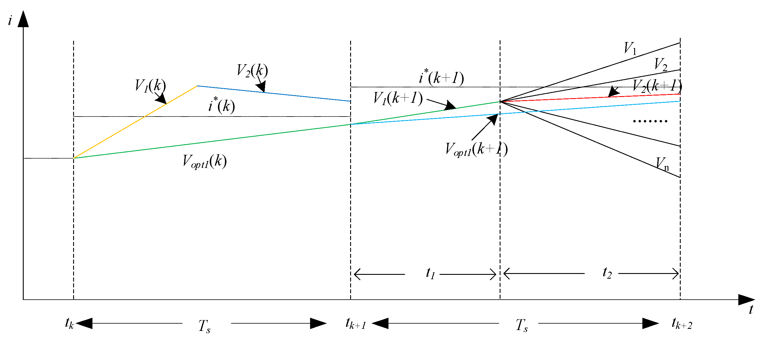
Select the optimal vector Vopt with an evaluation function though the single-vector exhaustive search and save the corresponding action error g1;
(4.2)
During the selection of a dual vector, the first switching vector is chosen as the one at the end of the previous cycle. The pre-allocated dwell time for Vopt1 and for the switching vector under evaluation is calculated through Formula (13). The pre-allocated time for Vopt1 is t1, and that for Vopt2 is t2. The predicted current values at time k + 2 are calculated respectively;
(5)
Substitute the predicted current values into the evaluation function as shown in Formula (12) and save the smallest action error g2.

5. Simulation and Experimentation

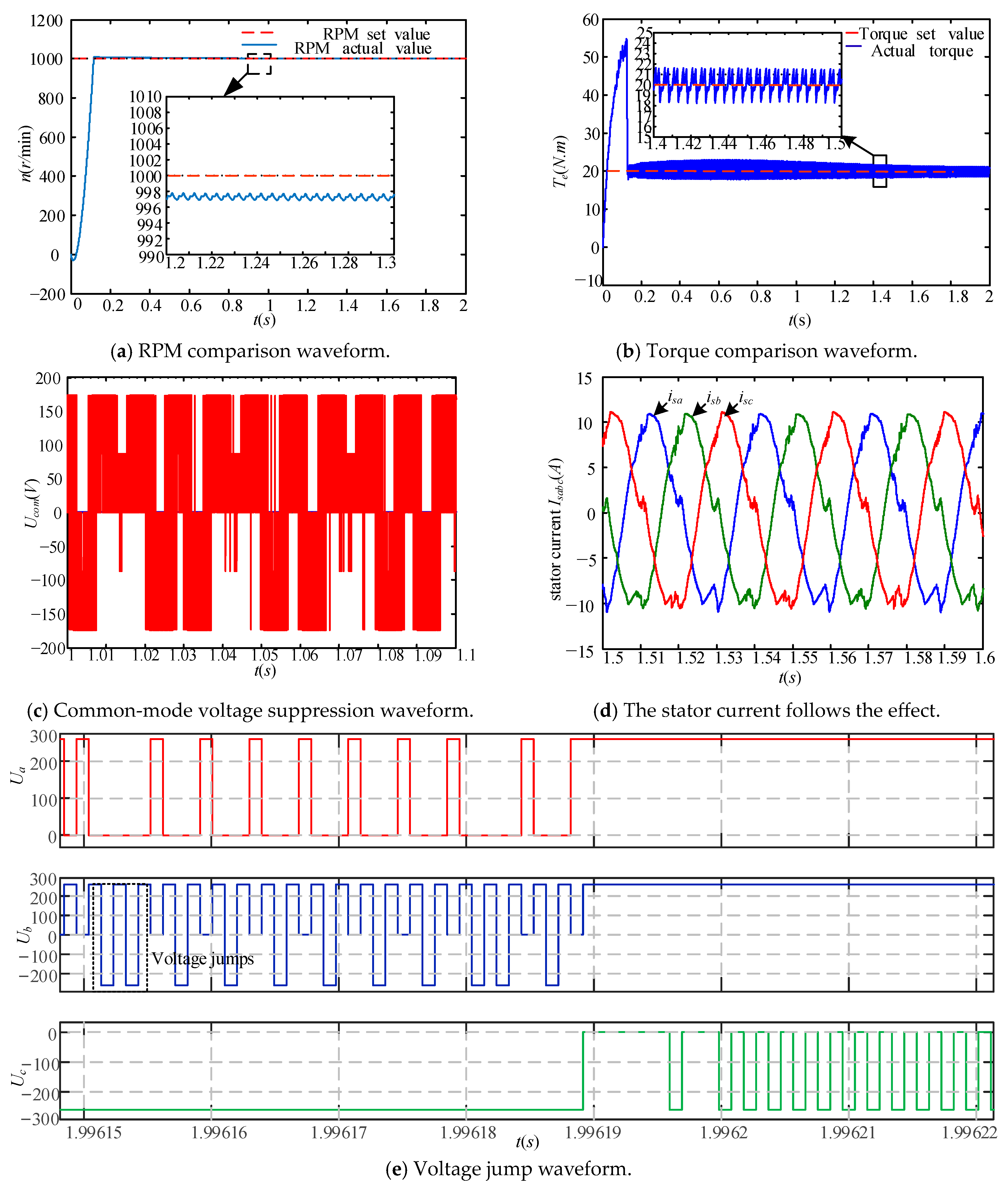
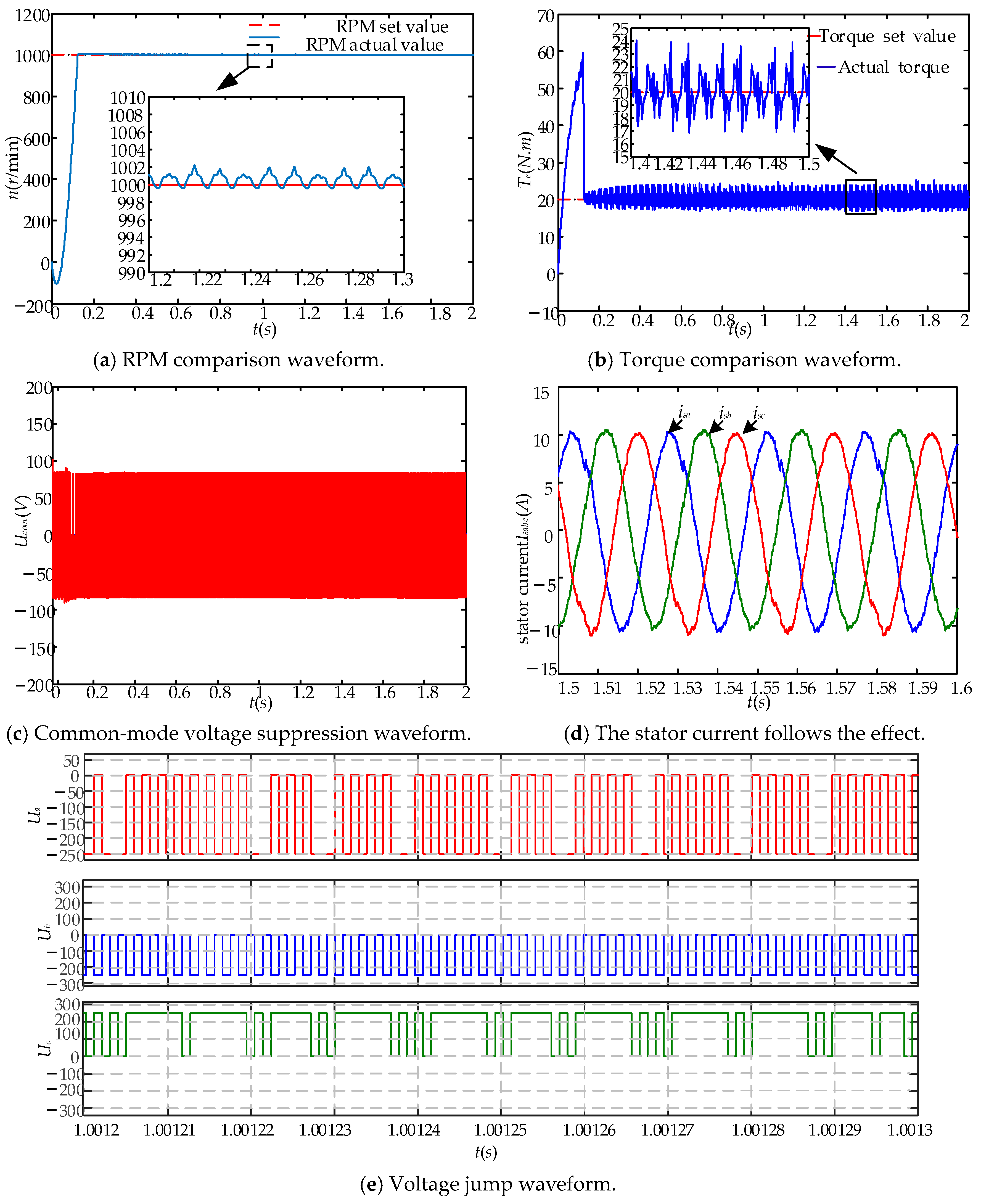
5.1. Simulation Analysis

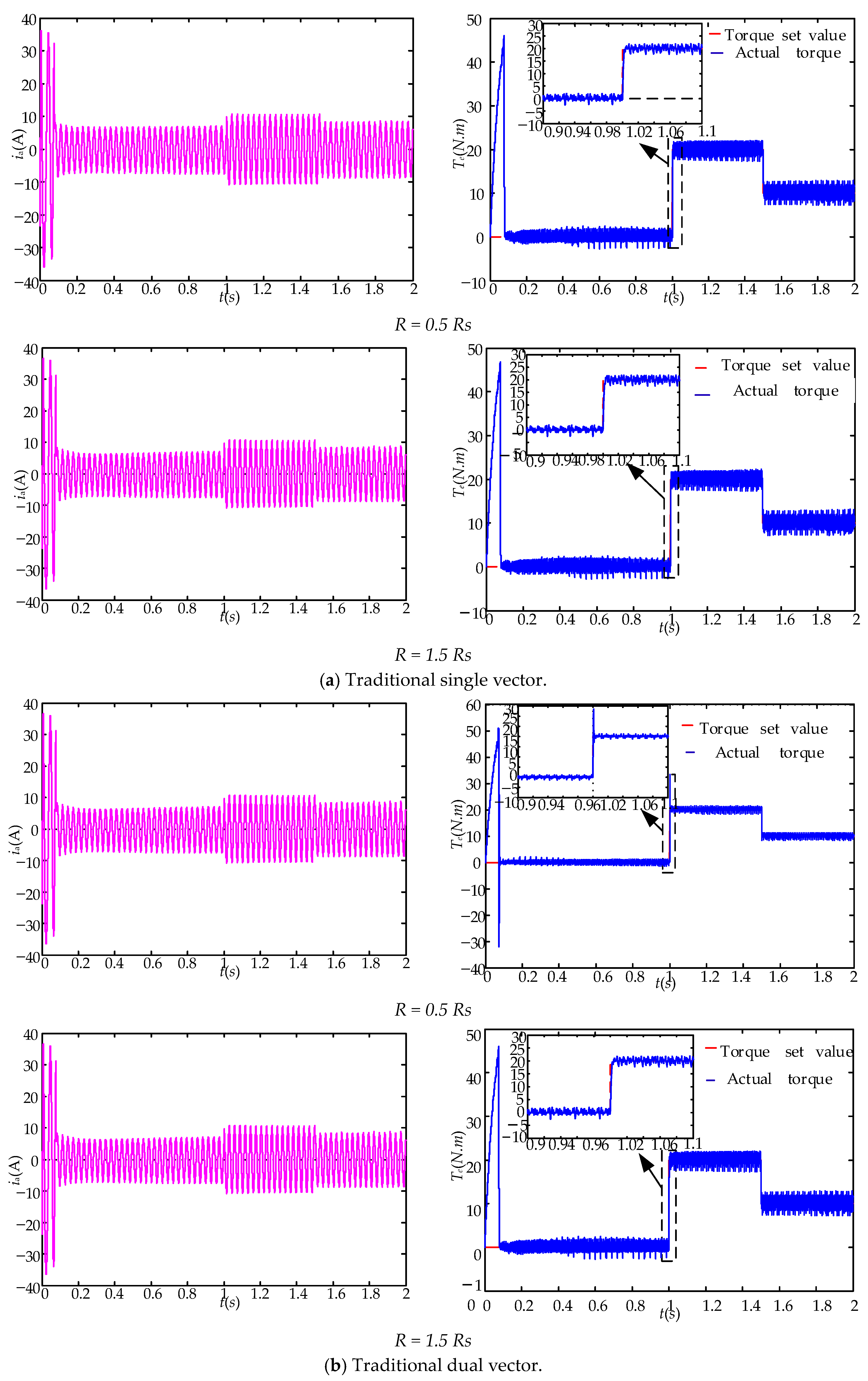
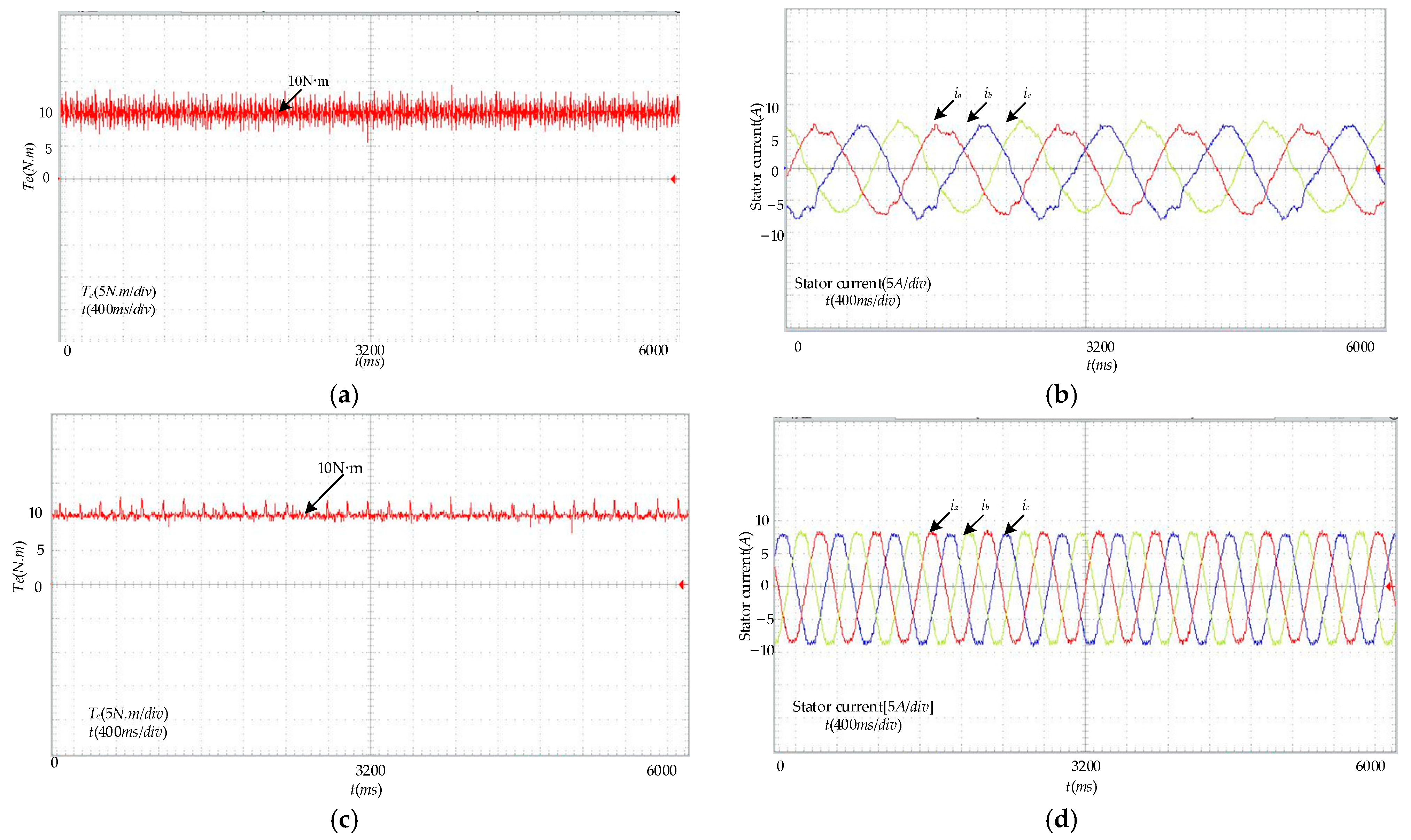
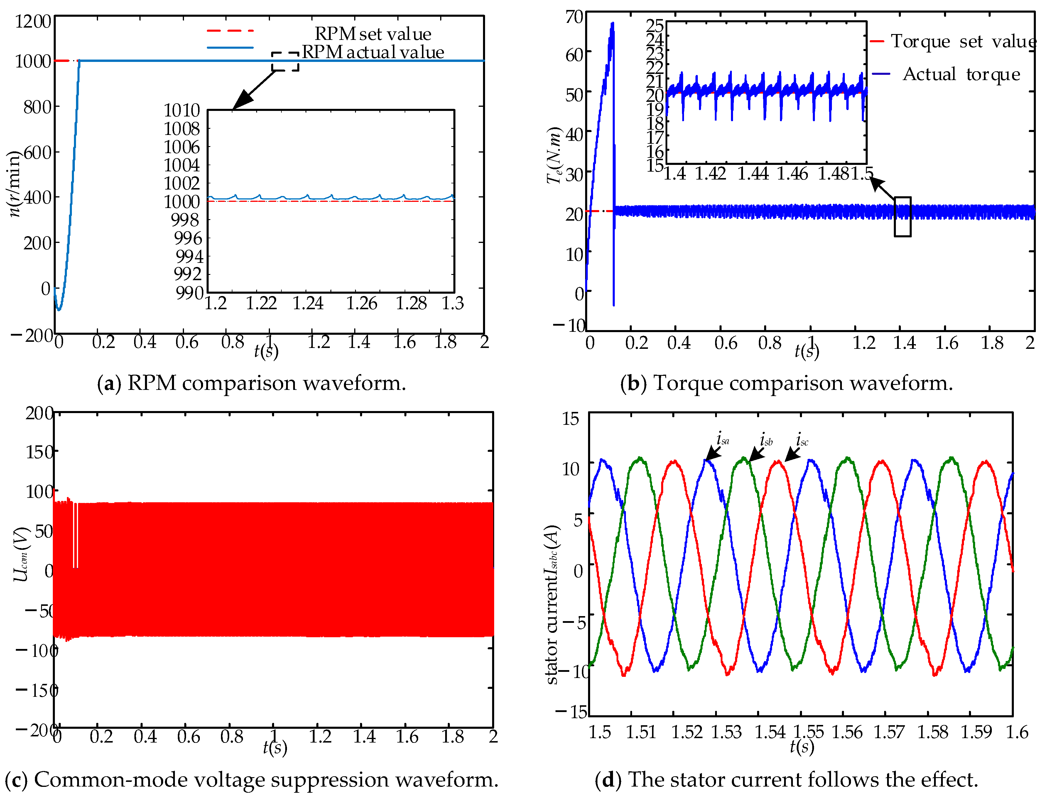
5.1.1. Steady-State Performance Analysis

Effectiveness is validated through simulation and experiment for the traditional single-vector model prediction, the single-vector model prediction without weight factors, and the two-stage model prediction without weight factors. The system sampling frequency is set at 10 kHz. The DC bus voltage is set at 520 V, and the voltage balancing capacitor value is 3000 μF. The parameters for the three-level inverter asynchronous motor are listed in Table 4.
Figure 6 presents the traditional single-vector simulation waveform with fixed-weight linear weighting. λ = 0.01. The motor starts under load with a load torque of 20 N·m. Figure 6a shows that the speed tracking error is 2 revolutions per minute. Figure 6b indicates that the average torque ripple is 2 N·m. Figure 6c suggests that the common-mode voltage amplitude fluctuates in the range [0 V, 180 V]. The high-amplitude common-mode voltage endangers motor insulation, which necessitates the rejection of common-mode voltage. Figure 6d also demonstrates that the traditional FCS-MPC output current has poor current sinusoidality and a high harmonic distortion rate. Figure 6e implies that, in the output phase voltage of the traditional single-vector FCS-MPC, there are numerous voltage jumps in Ub.
Figure 7 presents the simulation waveform without weight factors. Figure 7a shows that the speed tracking error is within 2 revolutions per minute. Figure 7b indicates that the average torque ripple is 2 N·m, implying significant torque fluctuations with large amplitude ripples. Figure 7c illustrates that the common-mode voltage amplitude is limited to 1/6 of the DC voltage, i.e., below 80 V, which achieves the control effect of the common-mode voltage. Figure 7d suggests that, compared with the single-vector FCS-MPC, the stator current has better current sinusoidality. Figure 7e demonstrates that there is no voltage overmodulation in the output phase voltage, meaning that voltage jumps are limited.
Figure 8 presents the simulation waveforms of the two-stage model prediction without weight factors. Figure 8a indicates that the speed tracking error tends towards zero, with minimal speed error observed. Figure 8b shows that the average torque ripple is 1 N·m, without significant torque ripple amplitudes. The simulation results demonstrate that the improved two-stage FCS-MPC effectively reduces the average torque ripples, exhibiting superior torque control performance. Figure 8c suggests that the common-mode voltage rejection exercises a similar effect. The current waveform depicted in Figure 8d shows the best current sinusoidality.
Table 5 presents the qualitative comparison of the three different strategies proposed in the above-mentioned simulation analysis. It is suggested that the two-stage FCS-MPC strategy without weight factors exhibits optimal performance. This approach has several advantages. Firstly, it is free from voltage jumps and the weight factor setting issues, and it allows for minimal common-mode voltage output control. Additionally, it can reduce computational load and manage to achieve current tracking. Secondly, the simulation results indicate that the improved two-stage MPC exhibits better steady-state speed tracking and successfully reduces torque ripples, manifesting the optimal torque control performance.

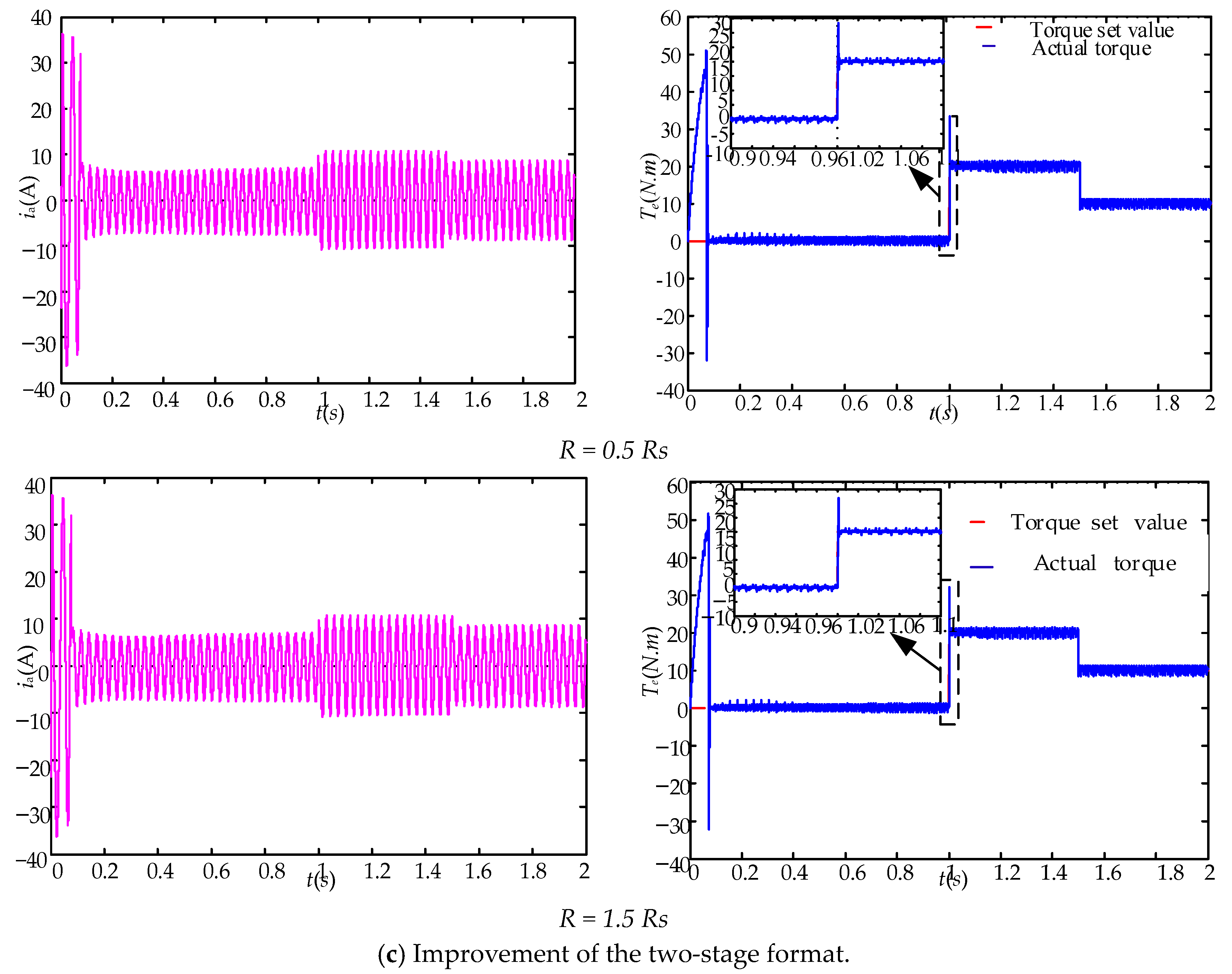
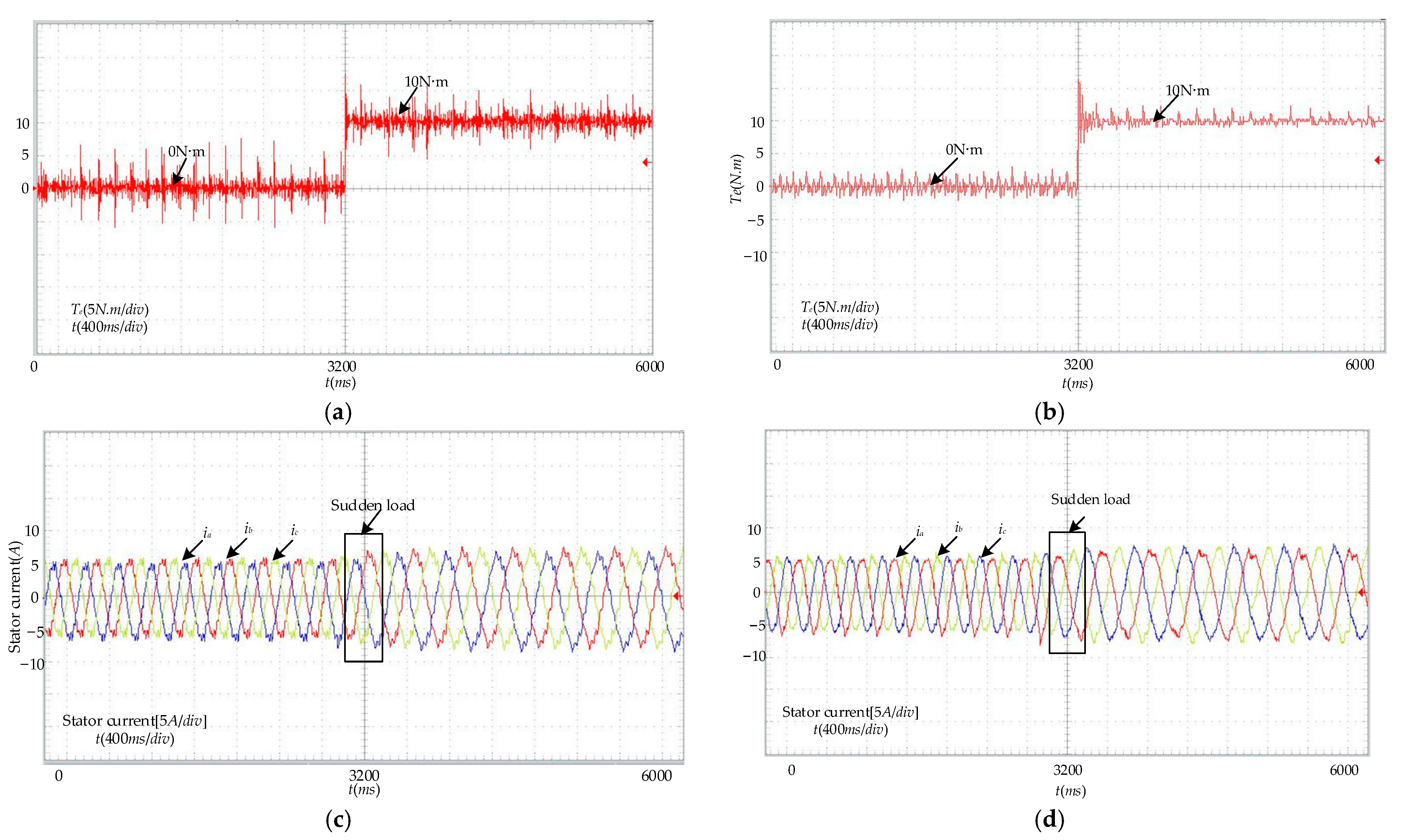
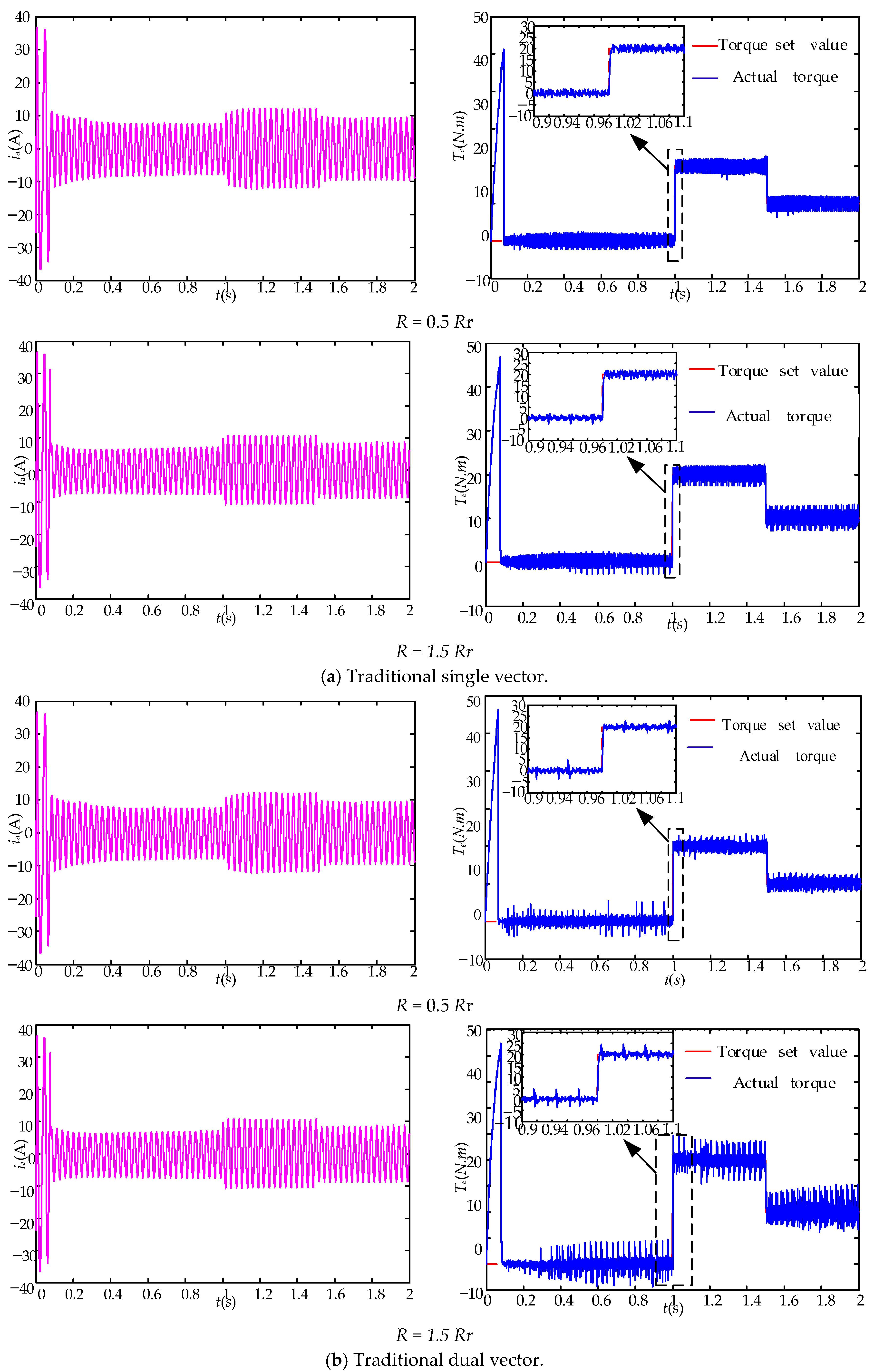
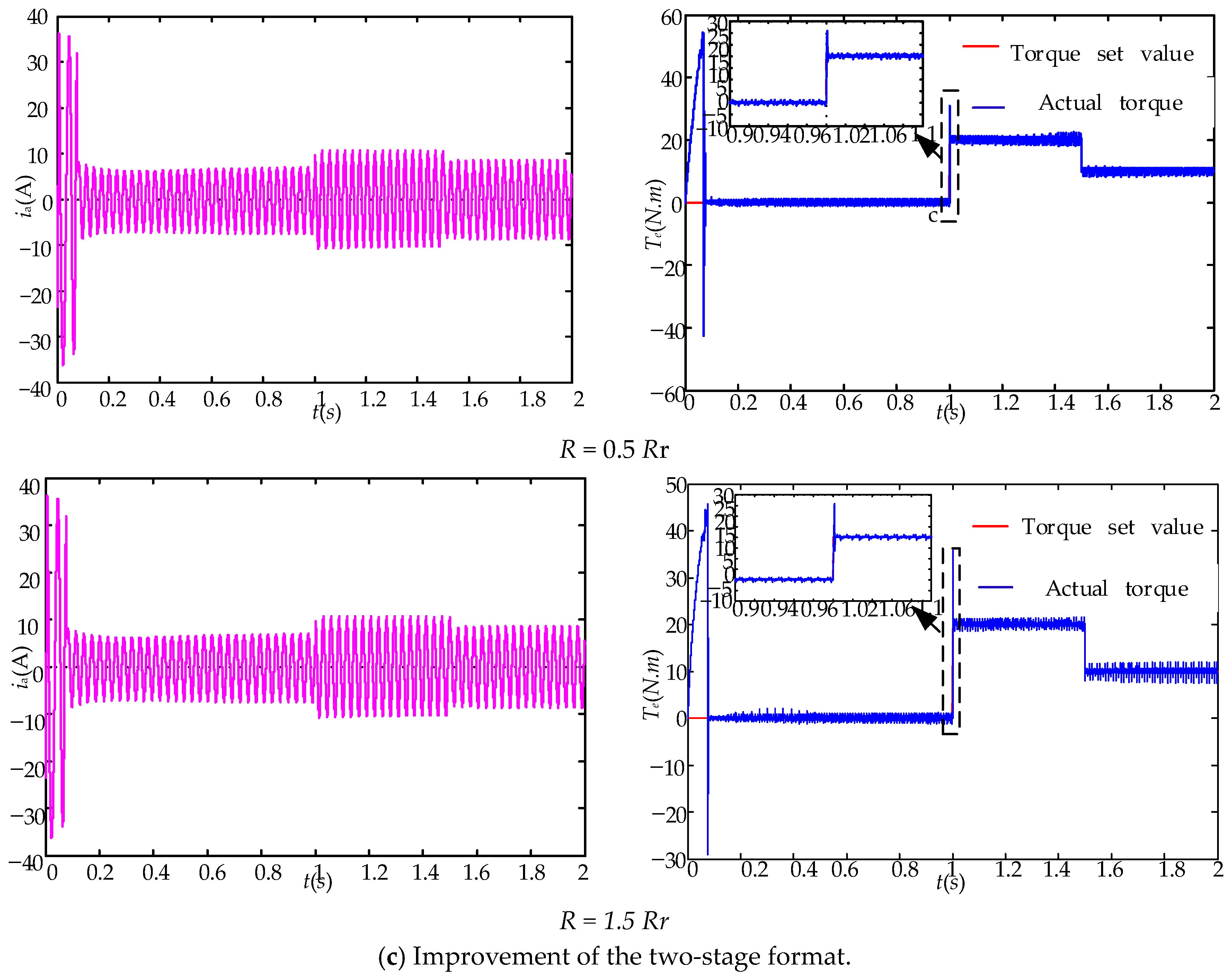
5.1.2. Dynamic Performance Analysis

(1)
Parameter Mismatch Analysis
In practical operation, the temperature of the motor’s stator and rotor will rise over time, which also leads to an increase in stator and rotor resistance. The motor inductance varies with magnetic saturation and frequency variations. The actual motor parameters may deviate from their rated values under different operating conditions. The parameter mismatch can directly impact the MPC’s control performance. Therefore, this paper conducts a simulation analysis of the control performance of the three strategies under conditions with stator and rotor resistance errors of ±50% and inductance errors of ±20% as follows:
(a)
Stator error analysis
In the analysis of stator resistance errors in asynchronous motors, the motor speed is set at 1000 r/min. The analysis considers situations where the stator resistance deviates by +50% and −50%, namely, where the stator resistance parameter in the predictive model of the asynchronous motor FCS-MPC is 1.5 times and 0.5 times its actual value. The stator current and the motor’s output torque under these conditions are observed.
Figure 9 presents the simulation waveforms of the three control strategies with stator resistance errors of ±50%. It is indicated that these three control strategies exhibit identical dynamic response time. The single-vector FCS-MPC and the dual-vector FCS-MPC demonstrate significant torque ripple. Particularly, when the stator resistance increases to 1.5 times its rated value, the dual-vector FCS-MPC ripple amplitude reaches 5 N·m. Figure 9c shows that the improved two-stage FCS-MPC maintains good torque performance with a ripple confined to 1 N·m when a deviation in stator resistance appears. The improved strategy has the smallest torque ripple. Simulation results indicate that the improved two-stage FCS-MPC provides better control performance when there is an error in stator resistance;
(b)
Rotor Resistance Error Analysis
In the analysis of rotor resistance errors in asynchronous motors, the motor speed is set at 1000 r/min. The analysis considers situations where the rotor resistance deviates by +50% and −50%, namely, where the rotor resistance parameter in the predictive model of the asynchronous motor FCS-MPC is 1.5 times and 0.5 times its actual value. The output current and the motor’s output torque are examined.
Figure 10 presents the simulation waveforms of the three control strategies with rotor resistance errors of ±50%. It is suggested that errors in rotor resistance exert a significant influence on the motor’s torque control performance. The response time of the two traditional control strategies is approximately 10 ms for mismatched rotor resistance and sudden changes in torque. The single-vector FCS-MPC and the dual-vector FCS-MPC show substantial torque ripple, with the maximum ripple amplitude nearing 10 N·m. The improved two-stage FCS-MPC is observed to have reduced torque control performance when the rotor resistance is 1.5 times its rated value, with torque ripple around 3 N·m. The simulation results indicate that the improved two-stage FCS-MPC has smaller torque ripple compared with traditional control strategies when errors in rotor resistance appear, manifesting superior torque control performance.

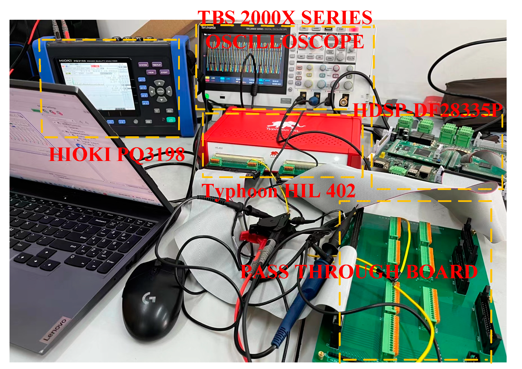
5.2. Experimental Verification

To validate the proposed strategy’s effectiveness, we set up an HIL experimental platform as depicted in Figure 11. In this setup, the primary circuit model is built in the Typhoon HIL402 platform, and the output pulses are generated by the HDSP-DF28335P controller. (Manufactured in China by Shanghai Hanxiang Intelligent Technology Co.).
Figure 12 shows the experimental waveforms of the traditional single-vector MPC and the output phase voltage without weight factors. As can be seen from Figure 12a, the traditional FCS-MPC does not limit voltage jumps, resulting in overstepping voltage changes. Figure 12b indicates that the FCS-MPC without weight factors restricts voltage jumps in the first layer, ensuring that there are no overstepping voltage changes, which is beneficial for the safe and stable operation of the system.
Figure 13 depicts the experimental waveforms of the common-mode voltage for both the traditional single-vector FCS-MPC and the FCS-MPC without weight factors. As shown in Figure 13a, the traditional single-vector FCS-MPC sets the common-mode voltage weight factor to 0.01, which can limit the amplitude of the common-mode voltage through a linear weighting approach. However, due to the numerous large amplitude fluctuations in the common-mode voltage, with a maximum approaching 200 V, it has a negative impact on motor insulation and system stability. Conversely, Figure 13b illustrates that the FCS-MPC without weight factors can effectively restrict the amplitude of the common-mode voltage to around 80 V, approximately one-sixth of the DC voltage. This indicates that the common-mode voltage is effectively controlled.
Figure 14 demonstrates the steady-state experimental waveforms based on the single-vector FCS-MPC without weight factors and the improved two-stage FCS-MPC without weight factors. As can be seen in Figure 14a,c, the average torque ripple for the single-vector FCS-MPC without weight factors is approximately 2 N·m, The improved two-stage FCS-MPC without weight factors exhibits an average torque ripple of approximately 1 N·m, effectively reducing the output torque ripple of the asynchronous motor. According to Figure 14b,d, the improved two-stage FCS-MPC has better current sinusoidality compared to the single-vector FCS-MPC without weight factors.
Figure 15 presents the dynamic experimental waveforms based on the single-vector FCS-MPC without weight factors and the improved two-stage FCS-MPC without weight factors. According to Figure 15a,b, under dynamic conditions, the average torque ripple for the single-vector FCS-MPC without weight factors is approximately 3 N·m, with significant torque ripple and a maximum amplitude over 2 N·m. In contrast, the average torque ripple for the improved two-stage FCS-MPC without weight factors under dynamic conditions is approximately 2 N·m, without any significant torque ripple. The experimental results demonstrate that the improved two-stage FCS-MPC without weight factors can effectively reduce the output torque ripple of the asynchronous motor, exhibiting excellent torque dynamic characteristics. As shown in Figure 15c,d, when a sudden load is applied, the improved two-stage FCS-MPC shows better current sinusoidality compared to the single-vector FCS-MPC without weight factors. The effectiveness and feasibility of the improved two-stage FCS-MPC without weight factors are well validated.

6. Conclusions

Given the problems in the application of an FCS-MPC strategy for a 3L-NPC-VSI, including the difficulty in setting weight factors, large torque ripple in single-vector control, and high switching losses in dual-vector control, this paper proposes a two-stage model predictive control strategy without weight factors. Firstly, the controller is divided into three layers, voltage jump constraint, common-mode voltage rejection, and current error tracking, based on the hierarchical optimization approach. This allows for control without weight factors and reduces the number of predictive calculations to 13. Then, the common-mode voltage is restricted to 1/6 of the DC voltage through a satisfactory optimization approach. Secondly, an improved two-stage FCS-MPC strategy is introduced in the current error tracking layer, effectively reducing the torque ripple to approximately 1 N.m. By modifying the dual-vector combination, the first vector is chosen as the one at the end of the current control cycle, ensuring that there is a maximum of only one switching state transition per control cycle. This maintains the average switching losses in each switch tube basically in line with that of the traditional single-vector FCS-MPC. Thus, dual-vector control is achieved without increasing switching losses. Lastly, detailed simulation and experimental analyses are conducted to verify the feasibility and effectiveness of the proposed strategy.

Author Contributions

Conceptualization, G.W.; validation, P.L.; investigation, Y.W. and P.L.; resources, G.W. and Y.W.; writing—original draft preparation, P.L.; writing—review and editing, G.W. All authors have read and agreed to the published version of the manuscript.

Funding

National Natural Science Foundation of China (grant no. 51707086).

Data Availability Statement

The original contributions presented in the study are included in the article, further inquiries can be directed to the corresponding author.

Conflicts of Interest

The authors declare no conflicts of interest.

References

  1. Chen, Z.; Wang, C.; Cheng, Q. Fast Model Predictive Control of Two-Level Inverter Based on Single Vector. Trans. China Electrotech. Soc. 2021, 36, 654–664+687. [Google Scholar]
  2. Xin, Y.; Wang, Y.; Li, G.; Wang, C.; Wang, W. Finite Control Set Model Predictive Control Method with Fast Optimization Based on T-Type Three-Level Grid Connected Inverter. Trans. China Electrotech. Soc. 2021, 36, 1681–1692. [Google Scholar]
  3. Li, X.; Xue, Z.; Yan, X. Voltage Vector Rapid Screening-Based Three-Vector Model Predictive Torque Control for Permanent Magnet Synchronous Motor. Trans. China Electrotech. Soc. 2022, 37, 1666–1678. [Google Scholar]
  4. Davari, S.A.; Khaburi, D.A.; Kennel, R. An Improved FCS–MPC Algorithm for an Induction Motor with an Imposed Optimized Weighting Factor. IEEE Trans. Power Electron. 2012, 27, 1540–1551. [Google Scholar] [CrossRef]
  5. Guo, L.; Zhang, K.; Wang, H. A predictive torque control method for permanent magnet synchronous motor without weighting factor. J. Light Ind. 2019, 34, 80–88. [Google Scholar]
  6. Zhang, X.; Hou, B. Double Vectors Model Predictive Torque Control without Weighting Factor Based on Voltage Tracking Error. IEEE Trans. Power Electron. 2018, 33, 2368–2380. [Google Scholar] [CrossRef]
  7. Garnica López, M.-A.; García de Vicuña, J.-L.; Miret, J.; Castilla, M.; Guzmán, R. Control Strategy for Grid-Connected Three-Phase Inverters During Voltage Sags to Meet Grid Codes and to Maximize Power Delivery Capability. IEEE Trans. Power Electron. 2018, 33, 9360–9374. [Google Scholar] [CrossRef]
  8. Lai, H. An Optimization Model Predictive Control Method for Three Level Inverters without Weighting Factor. Drive Control 2017, 45, 73–76+80. [Google Scholar]
  9. Wang, F.; Xie, H.; Chen, Q.; Davari, S.A.; Rodríguez, J.; Kennel, R. Parallel Predictive Torque Control for Induction Machines without Weighting Factors. IEEE Trans. Power Electron. 2020, 35, 1779–1788. [Google Scholar] [CrossRef]
  10. Xu, Y.; Li, Y. Logical Operation-Based Model Predictive Control for Quasi-Z-Source Inverter without Weighting Factor. IEEE J. Emerg. Sel. Top. Power Electron. 2021, 9, 1039–1051. [Google Scholar] [CrossRef]
  11. Sun, J.; Sun, H.; Jiang, J. An improved modulation method for low common mode current non-isolated series simultaneous power supply dual input inverters for new energy generation applications. Electr. Eng. 2024, 1–11. [Google Scholar] [CrossRef]
  12. Wang, X.; Lin, H.; Yang, H. The Characteristics and Suppression of Common-Mode Current for Brushless Doubly Fed Generator System. IEEE Trans. Electromagn. Compat. 2020, 5, 2265–2276. [Google Scholar] [CrossRef]
  13. Zhang, Y.; Bai, Y.; Yang, H. A Universal Multiple-Vector-Based Model Predictive Control of Induction Motor Drives. IEEE Trans. Power Electron. 2018, 33, 6957–6969. [Google Scholar] [CrossRef]
  14. Nasr, A.; Gu, C.; Wang, X.; Buticchi, G.; Bozhko, S. Torque-Performance Improvement for Direct Torque-Controlled PMSM Drives Based on Duty-Ratio Regulation. IEEE Trans. Power Electron. 2022, 37, 749–760. [Google Scholar] [CrossRef]
  15. Zhang, Y.; Yang, H. Generalized Two-Vector-Based Model-Predictive Torque Control of Induction Motor Drives. IEEE Trans. Power Electron. 2015, 30, 3818–3829. [Google Scholar] [CrossRef]
  16. Chen, W.; Zeng, S.; Zhang, G. A Modified Double Vectors Model Predictive Torque Control of Permanent Magnet Synchronous Motor. IEEE Trans. Power Electron. 2019, 34, 11419–11428. [Google Scholar] [CrossRef]
  17. Yao, J.; Liu, R.; Yin, X. Research on 3-Vector Model Predictive Control with Low Switching Frequency of Permanent Magnet Synchronous Motor. Trans. China Electrotech. Soc. 2018, 33, 2935–2945. [Google Scholar]
  18. Xu, Y.; Wang, J.; Zhang, B.; Zhou, Q. Three-Vector-Based Model Predictive Current Control for Permanent Magnet Synchronous Motor. Trans. China Electrote Chnical Soc. 2017, 33, 222–230. [Google Scholar]
  19. Xu, Y.; Wang, J.; Wang, J.; Zhao, J. Improved Two-vector Model Predictive Current Control Considering Prediction Errors. Electr. Drive 2018, 48, 62–66. [Google Scholar]
  20. Sangsefidi, Y.; Ziaeinejad, S.; Mehrizi-Sani, A. Low Switching Frequency-Based Predictive Control of a Grid-Connected Voltage-Sourced Converter. IEEE Trans. Energy Convers. 2017, 32, 686–697. [Google Scholar] [CrossRef]
  21. Feng, L.; Fu, J.; Guo, L.; Li, C. An Improved Low Switching Frequency Model Predictive Direct Torque Control Strategy for Traction Permanent Magnet Synchronous Motor. Proc. CSEE 2021, 41, 7507–7517. [Google Scholar]
  22. Lin, H.; Wu, X.; Le, S.; Song, W. Model predictive direct torque control of induction motor based on three level optimization vector. Electr. Mach. Control 2018, 22, 65–74. [Google Scholar]
  23. Wu, X.X.; Song, W.X.; Le, S.K.; Yuan, Y. Model Predictive Direct Current Control of Induction Machines Fed by a Three Level Inverter. Trans. China Electrotech. Soc. 2017, 32, 113–123. [Google Scholar]
  24. Vijayagopal, M.; Zanchetta, P.; Empringham, L.; De Lillo, L.; Tarisciotti, L.; Wheeler, P. Control of a direct matrix converter with modulated model predictive control. IEEE Trans. Ind. Appl. 2017, 53, 2342–2349. [Google Scholar] [CrossRef]
Figure 1. 3L-NPC-VSI circuit topology.
Energies 17 01813 g001
Figure 2. Traditional single-vector FCS-MPC block diagram.
Energies 17 01813 g002
Figure 3. Schematic diagram of improved two-stage FCS-MPC vector selection.
Energies 17 01813 g003
Figure 4. Selection schematic diagram of improved two-stage vector function.
Energies 17 01813 g004
Figure 5. Improved two-stage FCS-MPC block diagram.
Energies 17 01813 g005
Figure 6. Traditional FCS-MPC steady-state waveform.
Energies 17 01813 g006
Figure 7. Single-vector simulation waveforms without weighted factors.
Energies 17 01813 g007
Figure 8. Two-band simulation waveforms without weight factors.
Energies 17 01813 g008
Figure 9. Stator resistance error analysis.
Energies 17 01813 g009aEnergies 17 01813 g009b
Figure 10. Rotor resistance error analysis.
Energies 17 01813 g010aEnergies 17 01813 g010b
Figure 11. HIL experimental platform.
Energies 17 01813 g011
Figure 12. Output voltage experimental waveform.
Energies 17 01813 g012
Figure 13. Common-mode voltage waveform.
Energies 17 01813 g013
Figure 14. Steady-state torque experimental waveform. (a) Torque waveform of single-vector FCS-MPC without weight factors. (b) Improved single-vector unweighted-factor FCS-MPC torque waveform. (c) Torque waveform of improved two-stage FCS-MPC without weight factors. (d) Improved two-stage unweighted-factor FCS-MPC current waveform.
Energies 17 01813 g014
Figure 15. Dynamic torque waveform. (a) Torque waveform of single-vector FCS-MPC without weight factors. (b) Torque waveform of improved two-stage FCS-MPC without weight factors. (c) Current waveform of single-vector FCS-MPC without weight factors. (d) Improved two-stage unweighted-factor FCS-MPC current waveform.
Energies 17 01813 g015
Table 1. Three-level NPC inverter switch state table.
VoltageSa1Sa2Sa3Sa4States
Udc/21100P
00110O
Udc/20011N
Table 2. Common-mode voltage value corresponding to switch state.
TypeSwitch Status|ucom|
Large vectorPNN, NPN, NNP, PPN, NPP, PNPVdc/6
Mid vectorPON, OPN, NPO, NPO, ONP, PNO
ONN, NON, NNO, PPO, OPP, POP
0
Small vectorPOO, OPO, OOP, OON, NOO, ONOVdc/3
Zero vectorOOO
PPP, NNN
0
Vdc/2
Table 3. Common-mode voltage value corresponding to switch state. 3L-NPC-VSI performance index stratification.
Order of PriorityOptimized ContentIndicators
First layerVoltage jump limitsHard bound
Second layerCommon-mode voltage rejectionSatisfaction optimization
Third layerCurrent tracking errorModel prediction
Table 4. Common-mode voltage value corresponding to switch.
ParametersNumerical Values
Stator resistance/Ω1.55
Rotor resistance/Ω0.692
Stator inductor/H0.1384
Rotor inductor/H0.1384
Mutual sense/H0.133
Polar logarithm2
Table 5. Performance comparison of different policies.
Control PoliciesTraditional
Single Vector
Non-Weighted-Factor Single VectorNon-Weighted-Factor Two-Stage Formula
Speed error320
Torque ripple±4±2±1
Voltage transitionYesNoNo
Common-mode voltage±180±85±85
Current sinusoidalityWorstBetterBest
Disclaimer/Publisher’s Note: The statements, opinions and data contained in all publications are solely those of the individual author(s) and contributor(s) and not of MDPI and/or the editor(s). MDPI and/or the editor(s) disclaim responsibility for any injury to people or property resulting from any ideas, methods, instructions or products referred to in the content.

