Article

Air Purification Performance Analysis of Magnetic Fluid Filter with AC Non-Thermal Plasma Discharge

1
Department of Mechanical Engineering, Nippon Institute of Technology, Saitama 3458501, Japan
2
Department of Mechanical and Systems Engineering, Graduate School of Nippon Institute of Technology, Saitama 3458501, Japan
*
Author to whom correspondence should be addressed.
Energies 2024, 17(8), 1865; https://doi.org/10.3390/en17081865
Submission received: 25 March 2024 / Revised: 11 April 2024 / Accepted: 12 April 2024 / Published: 13 April 2024
(This article belongs to the Collection Feature Papers in Energy, Environment and Well-Being)

Abstract

:
Air pollution caused by particulate matter (PM) is a worldwide concern. PM is particularly problematic from fossil-fuel-based energy conversion devices. For PM collection, a low-pressure loss method is ideal. Although PM collection via electrostatic force is an effective method with low pressure loss for PM with a wide range of diameters, it is difficult to apply to low-resistive PM, such as diesel particulates, owing to re-entrainment on the collection electrode. A magnetic fluid filter with an AC non-thermal plasma discharge solves the problem of re-entrainment. Based on our previous study, we hypothesized that an increase in the number of magnetic fluid spikes leads to an improvement in collection efficiencies with energy conservation. In this study, experiments are performed to verify this hypothesis. By improving our previous experimental methodology, the experiments include not only collection efficiency but also pressure loss, power consumption, and ozone generation efficiency. PM collection efficiencies using diesel fine particles and the ozone generation efficiencies required for air purification are investigated under different discharge conditions. The results revealed that the PM collection and ozone generation efficiencies increase proportionally with the number of spikes of the magnetic fluid with discharge, as hypothesized. The resulting PM collection and ozone generation efficiencies are sufficiently high for air purification.

1. Introduction

Air pollution caused by aerosols is a worldwide concern. Due to the rapid industrialization of Asian countries, particularly China, and the accompanying increase in transportation demand, air pollution in the region is becoming serious [1]. Air pollution originating from anthropogenic sources is of particular concern. These pollutants include atmospheric nitrogen oxides (NOx), sulfur oxides, carbon monoxide and dioxide, and particulate matter (PM); NOx and PM emissions are key issues.
Air pollution due to PM, specifically PM2.5 (PM with an aerodynamic equivalent diameter less than 2.5 μm), is a worldwide environmental concern. Global averages reported that, in 2012, 25% of urban ambient PM2.5 came from traffic, 15% from industrial activities including power generation, 20% from domestic fuel burning, 22% from unspecified sources of human origin, and 18% from natural dust and sea salt [2]. In summary, the majority of PM originates from combustion; the sources include exhaust gas from diesel engines and combustion gas from boilers, that is, fossil-fuel-based energy conversion devices.
Aerosols with a diameter of 1 μm or less, including PM, can penetrate the lung alveoli in the human body and negatively affect health by causing respiratory illnesses. An effective solution incorporates PM removal in living spaces. An air purifier can be used for livings spaces such as houses, buildings, and factories. For air purifiers, dry-type filters are commonly used. The most widely used filters are high-efficiency particulate air filters (HEPA filters). However, these filters also suffer from the inherent problem of pressure loss. Pressure loss typically occurs up to 245 Pa. For an air purifier, in addition to efficient PM removal, effective sterilization and/or mold and bacteria proofing is also required, as aerosols contain not only PM but also pollen, bacteria, molds, and viruses.
PM emissions originate from the fossil fuels used in energy conversion devices. When comparing various sources of PM, particulates in the exhaust gas emitted from the combustion of fuel in combustion engines and boilers are the most critical. The main constituents of PM are carbon soot (C) and sulfur trioxide (SO3). For example, diesel engines offer many advantages such as high energy density of fuel, high efficiency, and relatively low carbon dioxide (CO2) emissions, along with lower volatile organic compound (VOC) emissions. These advantages make diesel engines favorable for many applications such as automobiles, ships, electric power generators, and construction machinery. Owing to their widespread use, there is considerable evidence for the contribution of diesel combustion towards PM.
In PM removal technologies, the collection of PM using devices based on electrostatic forces is effective for a wide range of PM diameters, including submicron particles, and this can be achieved with low pressure loss [3]. One such device that uses electrostatic forces for PM removal is the electrostatic precipitator (ESP) [4,5]. ESPs for PM from boilers have been developed [6,7]. Collections of combustion PM from small heat sources using corona discharge have also been studied [8,9].
PM collection technologies using electrostatic forces have been discussed in various reports [10,11]. An ESP using a magnetic field for the collection of PM2.5 was also proposed, and numerical analyses were carried out [12]. However, it is known that the collection efficiency of low-resistive PM is obstructed by re-entrainment in an ESP [13]. Therefore, ESPs are less effective if used directly to filter out the low-resistive diesel particulates and aerosols originating from combustion. Ideally, PM collection via electrostatic forces that can collect low-resistive PM must be employed; however, this remains challenging.
A PM collection technique using a magnetic fluid, also known as a ferrofluid or ferromagnetic fluid, together with non-thermal plasma (NTP) discharge has been proposed [14]. In this technique, a magnetic fluid “lump” attached to the wall of a flow channel with a magnet acts as a magnetic fluid filter. The surface area of the magnetic fluid is increased owing to the spiking property of a magnetic fluid under the influence of a magnet. As the exhaust gas containing PM passes over the magnetic fluid, the PM is collected over the surface of the magnetic fluid without any re-entrainment. In addition, PM collection is enhanced via the NTP discharge generated on the spikes of the magnetic fluid.
This method addresses the issues associated with the liquid film and HEPA filter. Moreover, the filter is mold- and bacteria-proof owing to the generation of ozone (O3) during the NTP discharge, which serves to sterilize the air in an air purifier. A previous study confirmed the feasibility of this collection technique [14]. The collection efficiencies with and without NTP were investigated in the filter with six lumps of the magnetic fluid. For further development of the magnetic fluid filter with NTP discharge, it is necessary to understand the collection mechanism, characteristics of collection, and power consumption for different conditions of NTP discharge.
Based on our previous study, we hypothesized that an increase in the number of magnetic fluid spikes leads to an improvement in collection efficiencies with energy conservation. In this study, experiments are performed to verify this hypothesis. By improving our previous experimental methodology, the experiments include not only collection efficiency but also pressure loss, power consumption, and ozone generation efficiency. The main objective is to investigate the effect of the number of spikes of the magnetic fluid on the collection efficiencies and ozone concentrations to obtain a fundamental understanding for further development of the magnetic fluid filter with NTP discharge. The number of spikes can be adjusted by the number of lumps of magnetic fluid. The conditions of NTP discharge from the magnetic fluid are varied and the associated PM collection efficiencies are investigated for each discharge condition. The collection efficiencies and power consumption of the magnetic fluid filter with NTP discharge are evaluated by comparing the PM count in the exhaust before and after passage through the filter. The PM collection mechanism of the magnetic fluid filter with NTP discharge is analyzed theoretically by means of migration velocities. Additionally, O3 concentrations generated by the magnetic fluid filters with NTP discharge are investigated under different discharge conditions.

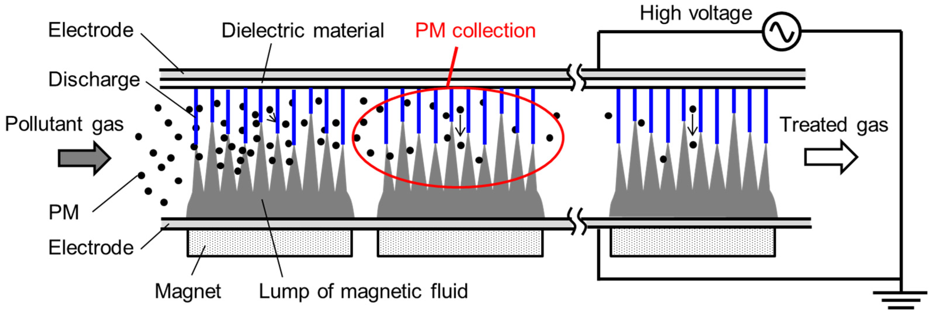
2. Physical Transport Phenomena and the Principle of PM Collection in a Magnetic Fluid Filter with NTP Discharge

2.1. Physical Transport Phenomena Contribution to PM Collection

In general, PM collection technologies utilize physical transport phenomena due to gravitational force, centrifugal force, inertial force, Brownian diffusion, and electrostatic force. Examples include gravity settling chambers, which use gravity; cyclone dust collectors, which use centrifugal forces; inertial impactors, which use inertial forces [15]; DPFs, which use Brownian diffusion; and ESPs, which use electrostatic forces. The first functional single-stage-type ESP was invented by Cottrell in 1908 [16]. A two-stage ESP using a positive DC corona was developed by Penney in 1937 [17]. This offers the advantage of design independence of the ionizing part and the collecting part, albeit with the drawback of increased structural complexity.
For the ionization process, both negative and positive corona discharges can be utilized. Negative corona discharge is widely used in industrial ESPs because of its suitability for the collection of a large amount of PM. Positive corona discharge is widely used for ESPs in air purifiers because of the low concentration of O3 by-product generation.
Two charging mechanisms exist in the ionizing part: field charging via the electric field or diffusion charging without the electric field. In field charging, ions accelerated by the external electric field collide with PM and the charge is proportional to the number of collisions. In diffusion charging, ions moving due to thermal energy that have sufficiently high energy happen to collide with PM, and the PM is charged as a result.
From a theoretical perspective, PM collection is dependent on the velocity of the particles due to gravity, centrifugal forces, inertial forces, Brownian diffusion, and electrostatic forces. Assuming that the PM particles are spherical and the associated Reynolds number is low (Rep < 2), Stokes’ law can be applied. The drag force (Fdrag) due to Stokes’s law is given by
F drag = 3 π μ v d p ,
where μ is the fluid viscosity, v is the relative velocity of the PM to the ambient fluid, and dp is the PM diameter. Considering non-continuum effects when the PM becomes significantly smaller, the Cunningham correction factor (Cc), which is a slip correction factor, is introduced into Stokes’ law, such that
F drag = 3 π μ v d p C c .
Generally, Cc is given by
C c = 1 + K n α + β e γ K n
where Kn is the Knudsen number, expressed as
K n = 2 λ d p
where λ is the mean free path of the fluid molecule. In the case of air, λ = 6.65 × 10⁻⁸ m at 298.15 K (25 °C) and 1 atm. α, β, and γ are theoretical or empirical correction parameters. Based on previous research, α = 1.257, β = 0.400, and γ = 1.100, as reported by Davies [18]; α = 1.142, β = 0.558, and γ = 0.999, as reported by Allen and Raabe [19]; and α = 1.165, β = 0.483, and γ = 0.997 for nanoparticles at 0.5 < Kn < 83, as reported by Kim [20]. For a gaseous ambient fluid, the PM velocities are as follows:
(1)
Migration velocity vg due to gravitational force (terminal settling velocity)
Using Stokes’ law for a small-Reynolds-number flow (Re < 2), the migration velocity vg due to gravitational force, or terminal settling velocity, is given by
v g = τ g = τ p τ f g
where τ is the relaxation time of the PM in the fluid, and g is the gravitational acceleration. The relaxation time of the PM τp and the relaxation time of the fluid τf are, respectively, expressed as
τ p = C c ρ p d p 2 18 μ   and   τ f = C c ρ f d p 2 18 μ
where ρp is the density of the PM, μ is the viscosity of the fluid, and ρf is the density of the fluid. For a gas, since ρpρf, the velocity vg can be simplified to
v g = τ p g .
(2)
Migration velocity vc due to centrifugal force
The migration velocity vc due to centrifugal force, or terminal velocity, is given by
v c = τ r ω 2 = τ p τ f r ω 2 = τ p τ f Z c g
where r is the rotation radius, ω is the angular velocity, and Zc is the centrifugal effect. For a gas, since ρpρf, the velocity vc can be simplified as
v c = τ p Z c g .
(3)
Migration velocity vi due to inertial force
The migration velocity vi due to inertial force is given by
v i = S t s = u 0 τ p t s
where S is the stopping distance. Specifically, S and ts are the distance and time taken, respectively, for the PM travelling at velocity u0 to come to rest owing to Stokes fluid resistance.
(4)
Migration velocity vB due to Brownian diffusion
Since displacement is the product of velocity and time, the migration velocity vB due to Brownian diffusion in the x-direction is expressed as
v B = x ¯ B t
where x B ¯ is the absolute mean displacement of the PM due to Brownian motion in a time of t s. Incorporating Cc in the displacement definition provided by Einstein [21], displacement can be expressed as
x ¯ B = 2 D B t = C c 2 k B T 3 π μ d p t
where DB is the coefficient of Brownian diffusion, kB is the Boltzmann constant (1.38 × 10⁻²³ J/K), and T is the absolute temperature.
(5)
Migration velocity ve due to electrostatic force
For a unipolar charger, the velocity ve due to electrostatic force is
v e = C c q E 3 π μ d p
where q is the charge and E is the strength of the applied electric field.
In the case of field charging, for dielectric PM, q is given by Pauthenier’s saturated charge, as follows:
q field = 3 ε p ε p + 2 π ε 0 E d p 2
where εp is the relative permittivity of the PM and ε0 is the permittivity of a vacuum (8.85 × 10⁻¹² F/m). For an ideal conductive PM, when εp → ∞, the equation becomes
q field = 3 π ε 0 E d p 2 .
In general, field charging acts predominantly on particles with sizes of 2 μm or higher.
In the case of diffusion charging, as reported by White [22], q is given by
q diff = n p e = 2 π ε 0 k B T e ln 1 + N ion e 2 v ion d p 8 ε 0 k B T t
where np is the number of particles, e is the elementary charge (=1.60 × 10⁻¹⁹ C), Nion is the ion concentration, and vion is the mean thermal velocity of the ions [23]. Diffusion charging acts predominantly on smaller particles, with sizes of 0.2 μm or less.
For a wide range of particle sizes, the migration velocity due to electrostatic forces is sufficiently large for effective PM collection, making it one of the most effective approaches. However, PM collection using electrostatic forces has proved problematic for low-resistive PM owing to re-entrainment on collection electrodes. To solve this problem, a magnetic fluid filter aided with NTP for collecting both high-resistive and low-resistive PM without causing any pressure loss has been developed.

2.2. Principle of PM Collection in a Magnetic Fluid Filter with NTP Discharge

A magnetic fluid is a colloidal solution consisting of fine ferromagnetic particles, with a typical size of 10 nm, suspended in a solvent with the help of surfactants. The fluid is superparamagnetic. Magnetite (Fe3O4) is commonly used for the ferromagnetic particles, which are coated with surfactants. The hydrophilic end of the surfactant attaches to the surface of the ferromagnetic particle, and the hydrophobic end attaches to an oil-based solvent (such as kerosene). The surfactant prevents the aggregation of ferromagnetic particles. In a water-based magnetic fluid, a double layer of the surfactants is coated on the ferromagnetic particles.
Spiking is a unique phenomenon exhibited by magnetic fluids, whereby spikes form along the magnetic field lines. Further, the pattern, density, and length of the spikes can be controlled by controlling the magnetic flux density. The formation of spikes is an interfacial phenomenon that is observed if the magnetic flux density exceeds a critical value [24]. For example, for a water-based magnetic fluid (W-40, Ichinen Chemicals Co., Ltd., Tokyo, Japan), the theoretical critical magnetic flux density is Bc = 86.6 × 10⁻⁴ T [25].
The working principle of the magnetic fluid filter with NTP discharge is illustrated in Figure 1. A gas that includes PM flows through the filter. In the filter, the magnetic fluid is suspended on the wall of the flow channel using a magnet. It is noted that Figure 1 is the schematic, and three sets of permanent magnets are used in the actual experiment. The formation of spikes and the required field strength to hold the magnetic fluid in position is controlled by the intensity and gradient of the magnetic field. The magnetic field generated by the magnets is used only to hold the magnetic fluid and generate spikes.
In this study, taking advantage of both positive and negative corona discharges, a high AC voltage is applied to the electrodes. With the application of the alternating voltage, NTP discharge occurs from the spikes of the magnetic fluid. The PM from the exhaust gas is charged and then collected on the surface of the magnetic fluid, with low-pressure loss. That is, the magnetic fluid plays the role not only of the discharge electrode but also the collection electrode. The presence of spikes increases the contact surface available for PM collection. In this case, large-diameter PM is collected via the inertial and gravitational forces, whereas small-diameter PM, such as nanoparticles, is collected is Brownian diffusion. In addition, electrostatic forces due to the NTP discharged from the spikes of magnetic fluid contribute towards the collection of PM with a wide range of diameters. In this method, even for low-resistive PM, the issue of re-entrainment on the collection electrode is resolved with the aid of the liquid interface adsorption on the magnetic fluid electrode. Therefore, the magnetic fluid filter aided with NTP discharge, with the absence of re-entrainment, is expected to collect low-resistive PM more efficiently than the conventional ESPs (with the help of the electrostatic force and contact with the liquid interface). NTP discharge from the spikes of the magnetic fluid and the O3 production have been reported in the literature [26]. O2 in the air contributes towards the formation of O3 via the O molecule (O) by NTP discharge according to the following reactions [27]:
O2 + e → O + O + e,
O + O2 → O3.
In the presence of H2O, in the form of moisture, a small quantity of O3 can generate an OH radical (•OH) with higher reactivity and oxidizability than other reactive species of oxygen. The OH radical is generated via the self-decomposition of O3 through reactions (19), (20) [28], (21), and (22) [29]:
O3 + OH → HO2 + O2,
O3 + HO2 → O3 + HO2,
O3 + H+ → HO3,
HO3 → •OH + O2.
Although the discharge is basically a dielectric barrier discharge (DBD), a discharge due to the local dielectric breakdown, such as corona discharge, occurs around the spikes of the magnetic fluid. As the magnetic fluid plays the role of the discharge electrode as well as the collection electrode, it achieves two-stage PM collection. Possible methods for the treatment of the collected PM include the replacement of the magnetic fluid, oxidation via O3 injection [30,31], or oxidation via the OH radicals and O3 generated during NTP discharge. The generated OH radicals and O3 also contribute to proofing against mold and bacteria in air purification [27].

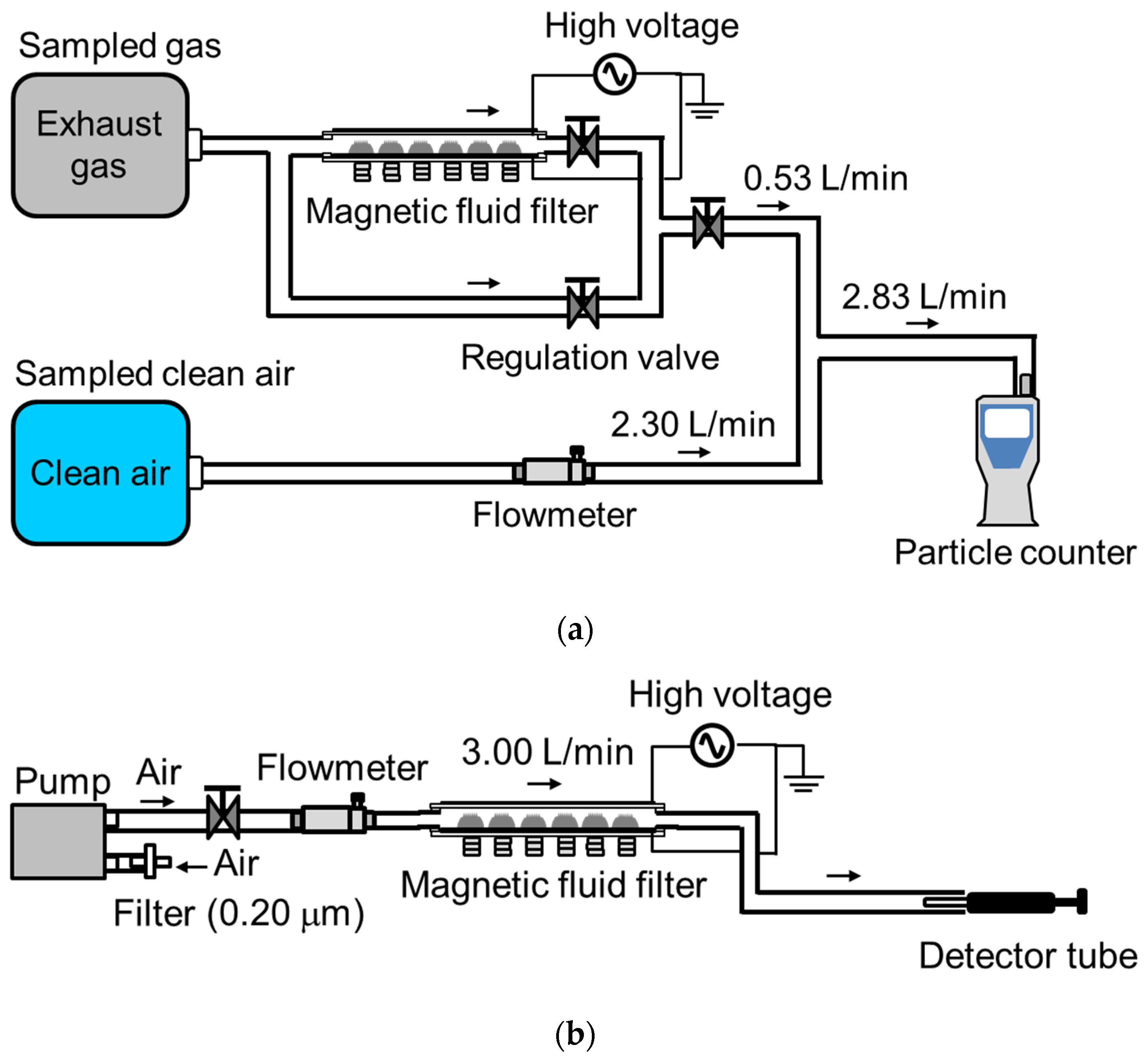
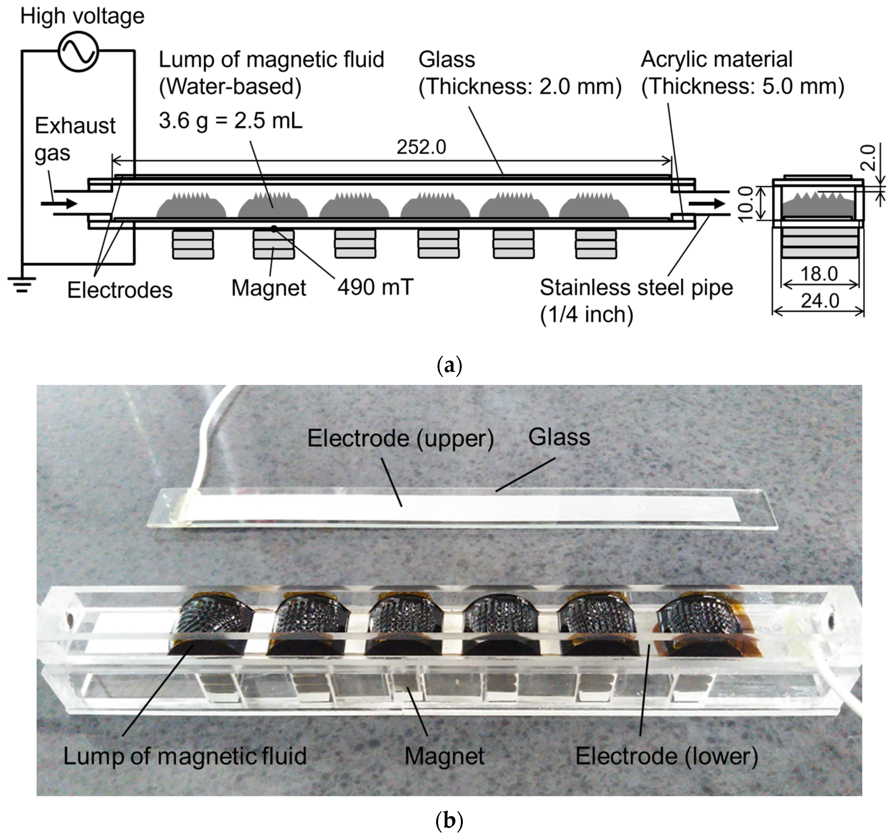
3. Experimental Setup and Method

A schematic of the experimental setup used for evaluating the PM collection efficiency of the magnetic fluid filter is presented in Figure 2a. A schematic of the setup used for the measurement of O3 concentration is shown in Figure 2b. Prior to the experiments for investigating and evaluating the performance of the filter, sampling of exhaust gas and clean air is carried out. Clean air is used for the dilution of the exhaust gas. To generate exhaust gas in a laboratory environment, diesel particulates from a diesel-engine power generator (KDE2.0E-60Hz, KIPOR, Wuxi, China) are used as low-resistive PM. The system combines a four-stroke direct injection diesel engine (KM170F) and a generator. The diesel engine is air-cooled using a single cylinder.
Diesel engine specifications: Rotational speed, 3600 rpm; cylinder bore, 70 mm; stroke, 55 mm; and displacement volume, 211 mL. The rated output power of the generator is 2.0 kVA. The exhaust gas flow rate is 380 L/min. An electric heater connected with the generator simulates the engine load. In this experiment, the engine load is set at 25% (=500 W). Exhaust gas travels directly from the engine exhaust into a gas sampling bag with a storage capacity of 20 L. In a separate gas sampling bag, clean air is collected by means of a vacuum pump. The clean air is produced by filtering atmospheric air through a membrane filter with a pore size of 0.20 μm.
A schematic of the designed magnetic fluid filter structure with the dimensions is depicted in Figure 3a, along with the associated photograph in Figure 3b. In the photograph, the upper electrode on the glass is removed from the filter body to indicate the magnetic fluid inside.
In the filter, the number of lumps of the magnetic fluid is varied between 1, 2, 4, and 6, as shown in Figure 4. A water-based magnetic fluid (W-40, Ichinen Chemicals Co., Ltd.) is used. The magnetic fluid is placed on the aluminum tape electrodes. Three sets of permanent magnets (neodymium magnets with a grade of N40) generate a surface magnetic flux density of 490 mT, higher than the critical Bc value. At the top of the magnetic fluid, in which the spike is formed, the magnetic flux density is 95 mT. A glass plate with a thickness of 2.0 mm, positioned beneath the upper electrode, is used as the dielectric.
To generate NTP discharge from the spikes of the magnetic fluid, a high alternating voltage is applied to the electrodes using a high-voltage power supply (LHV-13AC, Logy Electric Co., Ltd., Tokyo, Japan) with a capacity of 10 kV at a frequency of 9 kHz. Power consumption is measured using a wattmeter (TAP-TST7, Sanwa Supply Inc., Okayama, Japan). Exhaust gas from the sampling bag flows into the magnetic fluid filter and over the lumps of magnetic fluid, where the diesel particulates are collected. The volumetric flow rate of the exhaust gas is set to 0.53 L/min using a regulation valve. This limits the PM that enters the particle counter. In addition, the flow rate at the intake of the particle counter is fixed, accounting for the capacity of the particle counter and allowing for accurate measurements. The filtered gas that flows out of the magnetic fluid filter is diluted using clean air from the sampling bag, considering the limited counting capacity of the particle counter. The flow rate of the clean air is maintained at 2.30 L/min, monitored using a flowmeter (PFM710, SMC Corporation, Tokyo, Japan).
A bypass is installed at the inlet of the magnetic fluid filter. The gas is collected through the bypass route when counting the diesel particulates in the unfiltered exhaust gas for the control experiment. The exhaust gas is diluted with the sampled clean air in the same manner as for the filtered gas. The diluted (filtered as well as unfiltered) gas flows into the particle counter (HHPC 3+, Beckman Coulter, Inc., Pasadena, CA, USA). The measurement range of the particle counter is from 0.3 μm to 10 μm. The volumetric flow rate of the gas for the particle counter is fixed at 2.83 L/min.
The PM count output of the particle counter is converted to the original count prior to dilution, and the PM counts before and after filtration are obtained. The PM count in the unfiltered exhaust gas (Nexh), the PM count after filtration only via the magnetic fluid (NMF), and the PM count after filtration via the magnetic fluid aided with NTP (NMFNTP) are used for calculating the PM collection efficiencies, which are defined as follows:
η MF = N exh N MF N exh ,
η MFNTP = N exh N MFNTP N exh .
For the measurement of the O3 concentration generated, clean air is supplied to the filter (shown in Figure 2b) using a pump equipped with a membrane filter featuring a pore size of 0.20 μm. The volumetric flow rate of the source gas is set to 3.00 L/min using a regulation valve. The source gas flows into the magnetic fluid filter with NTP. The magnetic fluid filter and discharge conditions are the same as those used in the PM collection measurements. At the outlet of the magnetic fluid filter, the O3 concentration is measured. A detector tube (No. 18M, Gastec Corporation, Kanagawa, Japan) is used to measure the O3 concentration.
O3 generation efficiency ζO3 is introduced to evaluate O3 generation performance. ζO3 (in mg/Wh) is given by
ς O 3 = Q in t C O 3 10 3 M O 3 V mol 1 P
where the flow rate of air at the inlet is Qin = 3.00 L/min, t is the time (t = 60 min), CO3 is the average measured O3 concentration (ppm), MO3 is the molar mass of O3 (MO3 = 48), Vmol is the molar volume (22.4 L/mol for 0 °C = 273.15 K and 1 atm; 24.8 L/mol for 25 °C = 298.15 K and 1 atm), and P is the measured power consumption (W).

4. Results and Discussion

4.1. PM Collection in a Magnetic Fluid Filter

In the magnetic fluid filter, the number of lumps of magnetic fluid n are varied between 1, 2, 4, and 6. For all values of n, simultaneous NTP discharges from the spikes on the magnetic fluid lumps are observed. The spikes have a square base (typically 2 mm × 2 mm) and a height of 1.5–2.0 mm. In the experiment, six data sets are obtained per configuration, and the average value is calculated. For the case of n = 1, two optional positions for the magnetic fluid lump are tested, as shown in Figure 4. Six data sets are obtained for each position, that is, twelve data sets in total for n = 1. The average value for the twelve sets is then calculated for n = 1. However, the results show no difference in terms of the PM collection measurement between these two positions.
Figure 5a shows the resulting PM collection efficiency in the magnetic fluid filter without NTP, ηMF. Figure 5b shows the resulting PM collection efficiency in the magnetic fluid filter with NTP, ηMFNTP. The graph indicates the relationship between the PM diameter in the measurement range dp and the PM collection efficiency ηMF or ηMFNTP for different values of n. The average values and the standard errors are indicated in the graph.
The average number of diesel particulates in the raw sampled exhaust gas are 2.27 × 10⁶ particles/L for diesel particulates with diameter dp ≥ 0.3 μm, 2.16 × 10⁶ particles/L for dp ≥ 0.5 μm, 1.76 × 10⁶ particles/L for dp ≥ 1.0 μm, 1.26 × 10⁶ particles/L for dp ≥ 2.0 μm, 4.98 × 10³ particles/L for dp ≥ 5.0 μm, and 0 (not detected) for dp ≥ 10.0 μm.
For the case of n = 6; ηMF = 34, 68, 96, 100, and 100% for diesel particulates with dp ≥ 0.3, 0.5, 1.0, 2.0, and 5.0 μm, respectively. In this case, the inertial and gravitational forces and Brownian diffusion contribute towards the PM collection. The application of NTP improves the PM collection efficiencies with the aid of the electrostatic force. As a result, ηMFNTP = 71, 90, 99, 100, and 100% for diesel particulates with dp ≥ 0.3, 0.5, 1.0, 2.0, and 5.0 μm, respectively. PM with dp ≥ 0.5 μm can be collected with ηMFNTP ≥ 90%, which is the collection efficiency generally required for air purifiers. As dp increases, ηMFNTP also increases for all n. As n increases, ηMFNTP also increases. In other words, ηMFNTP increases proportionally with an increase in the surface area at which PM collection occurs. The resulting ηMFNTP = 71% for diesel particulates with dp = 0.3 μm could be improved by increasing n. In particular, the results demonstrate that diesel particulates with dp = 0.3–1.0 μm can be controlled by n. In addition, it is considered that the electrostatic force contributes to the collection, as the collection efficiency of these particles is significantly improved by the NTP discharge.
By comparison, collection efficiencies in the electrostatic zone of the recent hybrid filters that integrate an ESP and bug filter are 46–87, 48–90, and 50–97% for dp = 0.5, 1.0, and 2.0 μm, respectively [32]. The magnetic fluid filter with NTP, thus, exhibits equivalent or superior performance to hybrid filters.
To discuss these results and investigate the PM collection mechanism, the migration velocity is calculated for different transport mechanisms in the present experiment. In the calculation, Equations (1)–(7) and (10)–(16) are considered. Equations (8) and (9) are not used because the centrifugal force does not contribute towards this PM collection. As a reference, the parameter values are considered as follows: ρp = 1000 kg/m3, μ = 1.84 × 10⁻⁵ Pa·s in air at 298 K and 1 atm, g = 9.81 m/s2, ts =1.00 s, and T = 298 K. For Cc, α = 1.257, β = 0.400, and γ = 1.100 for micro-size PM with dp ≥ 1.00 μm and α = 1.165, β = 0.483, and γ = 0.997 for nano-size PM with dp < 1.00 μm. For ve, the values of the parameters are E = 50 kV/cm (10 kV for NTP discharge in the 2 mm gap between the spike of magnetic fluid and the electrode), Nion = 1.00 × 10¹³/m3, and virons = 2.38 × 10² m/s for positive charging and 3.00 × 10² m/s for negative charging [33]. Figure 6a shows the relationship between the diameter of PM and the migration velocity for each transport mechanism. The migration velocity due to inertial forces is calculated as the gas flows into the magnetic fluid filter at a flow rate of 0.53 L/min. In this case, u0 = 0.05 m/s. The measuring range of PM diameters is also indicated in the figure. The migration velocity due to electrostatic forces is the combination of the velocity due to field and diffusion charging, and the solid line shown approximates the two charging effects considered. For larger PM with dp ≥ 0.50 μm, the migration velocities due to gravitational and inertial forces are sufficiently large for effective PM collection. For smaller PM with dp < 0.50 μm, the migration velocities due to Brownian diffusion are sufficiently large for effective PM collection. Electrostatic forces include field charging, which is dominant for large particles, and diffusion charging, which is dominant for small particles. The effective electrostatic force is indicated in the figure as a solid line.
Figure 6a also depicts the contribution of the internal and gravitational forces and Brownian diffusion towards PM collection in the absence of NTP, although these migration velocities are small. Hence, it can be inferred that the flow characteristics in the filter are also a contributing factor. The correlation between PM collection and flow characteristics will be investigated in future research. A previous study confirmed that electrostatic forces enhance PM collection [14], as does this study. Figure 6a shows that the migration velocity due to the effective electrostatic force is considerably greater than that due to other forces. Furthermore, it increases with the PM diameter in the measurement range. Figure 6b shows the time for the PM to travel 2 mm, which is a typical discharge distance from the spike to the electrode, under electrostatic forces for different PM diameters. For the alternating discharge of 9 kHz, the NTP discharge switches sign every 1.11 × 10⁻⁴ s, as indicated by the dashed line in the figure. When the effective traveling time is less than the dashed line, PM can be instantly adsorbed at the magnetic fluid interface by the NTP discharge. In other words, for PM with dp ≥ 1.2 μm, there exists a high probability that collection via electrostatic forces will occur, which is consistent with the experimental results of the collection efficiency, ηMFNTP. However, it is possible that the PM could escape from the discharge and not be collected, especially for a small n. Even if the traveling time is greater than that shown by the dashed line, as is the case for dp < 1.2 μm, ηMFNTP can be improved if the probability that the PM comes in contact with the discharge is increased by increasing n. Therefore, the ηMFNTP obtained in the experiment improves as n increases, even for dp < 1.2 μm. In this study, the discharge voltage is constant. However, Equation (13) suggests that ve is enhanced by the strong electric field with a high discharge voltage. In other words, a higher discharge or input voltage to the power supply could improve the PM collection via electrostatic force.
Figure 7 shows the relationship between the number of lumps of magnetic fluid n and the pressure loss across the magnetic fluid filter Δp for an inlet air flow rate of Qin = 2.83 L/min, whereas Qin = 0.53 L/min in the PM collection experiment. Δp is measured using a differential pressure gauge (DPG-01U, Custom Corporation, Tokyo, Japan) at the inlet and outlet of the magnetic fluid filter, in which the stainless-steel pipe is installed. In this case, the flow velocity in the magnetic fluid filter is u = 0.26 m/s, whereas the flow velocity on the top of the lumps of magnetic fluid is typically umax = 0.90 m/s. The approximate line is indicated as a solid line. The magnetic fluid filter container is a sudden expansion and contraction structure. Therefore, even in the absence of magnetic fluid, there is a pressure drop Δp0 = 44 Pa at n = 0. The pressure loss is expressed by following Equation (26), and Δp = 46 Pa at n = 6.
Δ p = Δ p 0 + Δ p MF   with   Δ p MF = 0.3 n .
As a result, the pressure loss due to the presence of magnetic fluid ΔpMF is 1.8 Pa at n = 6 with u = 0.26 m/s and umax = 0.90 m/s. This pressure loss is caused by the flow path geometry due to the presence of magnetic fluid, and it could be improved by optimizing the arrangement of lumps of magnetic fluid. This ΔpMF can be considered sufficiently low by taking into account the pressure loss of the recent electrostatic filters with low pressure loss, for example, 3.8 Pa at 1.1 m/s filtration velocity [3] and 4.9 Pa at 0.1 m/s [34]. Furthermore, this result exhibits a significant advantage as it shows a much smaller pressure loss compared to that of a generic HEPA filter.

4.2. Power Consumption of NTP Discharge in a Magnetic Fluid Filter

Figure 8 relates the number of lumps of magnetic fluid n to the power consumption associated with the discharge P. It is worth noting that P is the total power consumption, including the power loss in the power supply circuit in addition to the discharge power. After a 30 s warm-up period, five measurements of power consumption are taken every 10 s for 60 s, and the average values and standard errors are shown in the graph. The maximum power consumption is P = 49 W at n = 1. It appears that the current density per discharge is high and stable at n = 1. However, when n = 2, P decreases to the minimum of 42 W. It appears that the current density per discharge is weak and unstable at n = 2. As n increases to 4 and 6, P gradually increases to 44 and 47 W, respectively. The discharge current density from spikes and the number of spikes are considered to affect power consumption. The higher power consumption at n = 1 implies that the discharge current density produced by a spike is high. Considering the small difference in P for n = 1–6 and the results of ηMFNTP, the hypothesis that an increase in spikes leads to improved collection efficiencies with energy conservation has been validated.

4.3. O3 Generation of a Magnetic Fluid Filter

Figure 9a shows the relationship between the number of lumps of magnetic fluid n and the O3 concentration CO3 for an inlet air flow rate of Qin = 3.00 L/min. The ambient temperature and humidity are 17 °C = 290.15 K and 39%, respectively. The average values and standard errors are also shown. A quadratic polynomial approximation trend curve is plotted. The O3 concentrations are 20, 47, 72, and 187 ppm at n = 1, 2, 4, and 6, respectively, and CO3 increases with n. Figure 9b shows the relationship between the number of lumps of magnetic fluid n and the O3 generation efficiency ζO3. The resultant ζO3 and the approximate curve using a quadratic polynomial approximation are graphically represented. For 0 °C and 1 atm, the ζO3 values are 0.15, 0.43, 0.63, and 1.53 mg/Wh at n = 1, 2, 4, and 6, respectively. For 25 °C and 1 atm, the ζO3 values are 0.14, 0.39, 0.57, and 1.39 mg/Wh at n = 1, 2, 4, and 6, respectively. This shows that ζO3 increases as n increases. This result is concluded to be due to the small difference in P for n = 1–6, whereas CO3 increases as n increases.
It can be seen that performance efficiency improved in both PM collection and ozone generation with an increase in the number of lumps of magnetic fluid or with an increase in the number of spikes of the magnetic fluid. This means that ozone production is more affected by the number of spikes than by the current density discharged from the spikes.

5. Conclusions

In this study, the conditions of NTP discharge from a magnetic fluid are varied by varying the number of lumps of magnetic fluid, and the PM collection efficiencies and power consumption are investigated for different discharge conditions. It is noted that the magnetic field plays a role of holding the magnetic fluid and generating spikes on the surface of the magnetic fluid. Because the magnetic and electric fields are parallel, the Lorentz force is small and its contribution to collection could be small. They are evaluated using the PM count in the exhaust before and after passing through the filter. The O3 concentrations generated are also investigated for different discharge conditions.
The conclusions of this study can be summarized as follows:
(1)
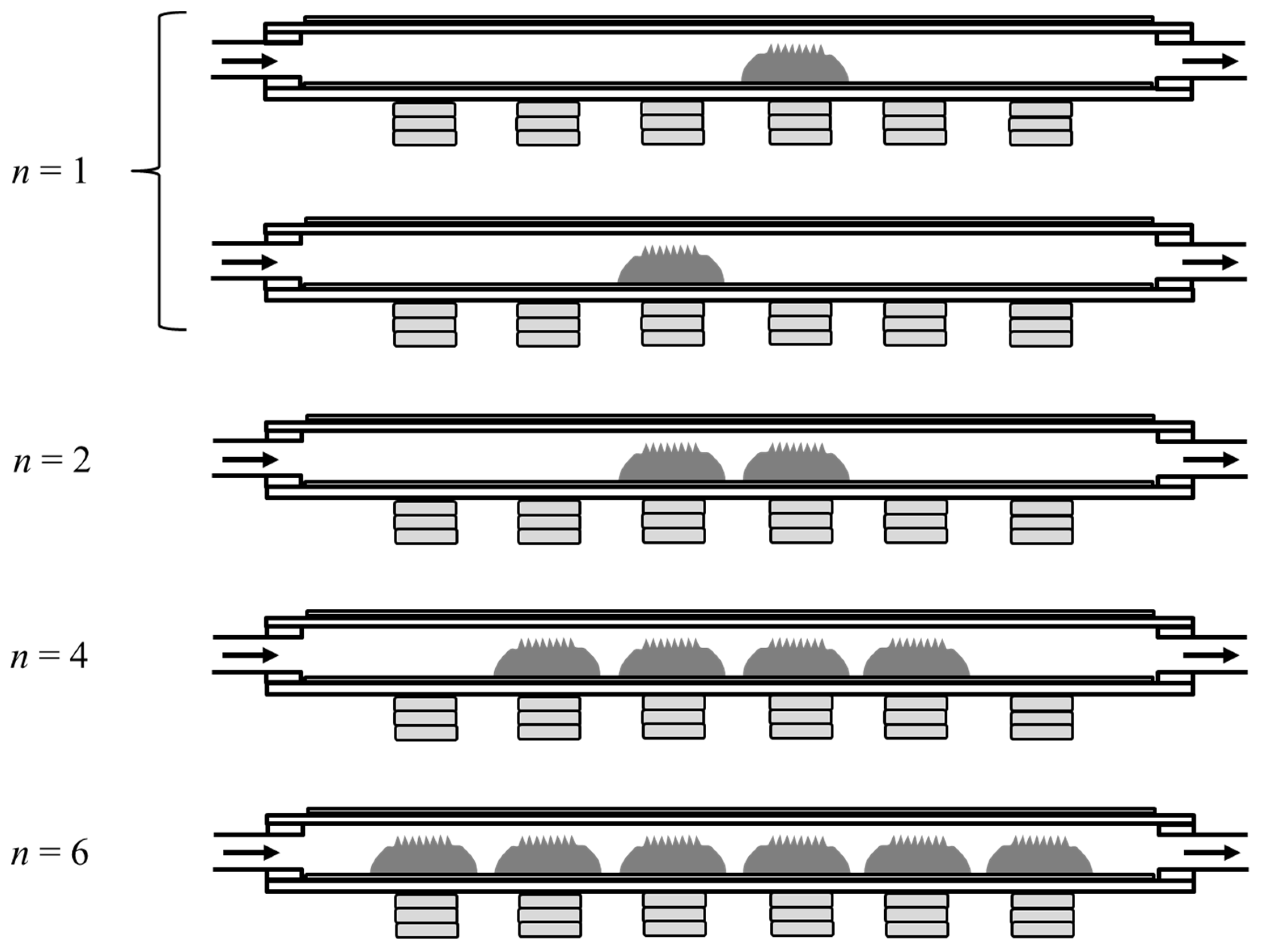
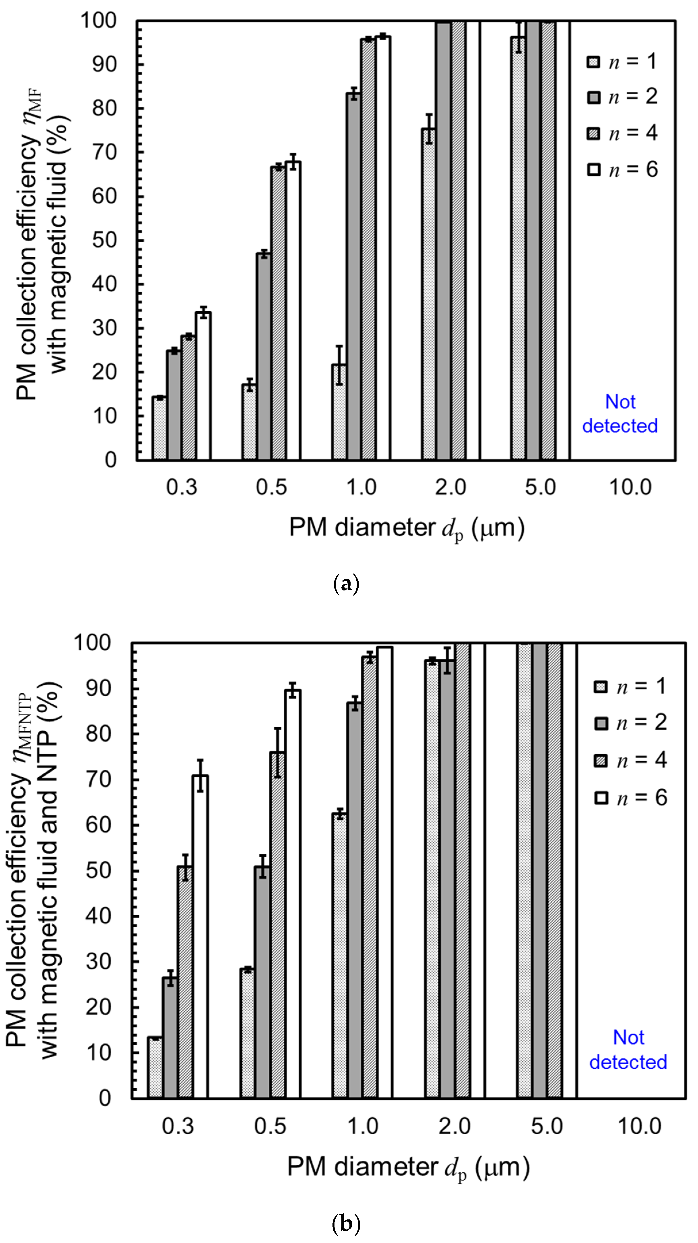
The relationship between the minimum diameter of PM in the measurement range dp and the PM collection efficiency with NTP ηMFNTP for different numbers of lumps of magnetic fluid n are investigated. Under n = 6, ηMFNTP = 71, 90, 99, 100, and 100% for dp ≥ 0.3, 0.5, 1.0, 2.0, and 5.0 μm, respectively. These collection rates are sufficiently high for air purification. As dp increases, ηMFNTP also increases at all values of n. As n increases, ηMFNTP increases. The PM collection mechanism is a function of the particle migration velocity.
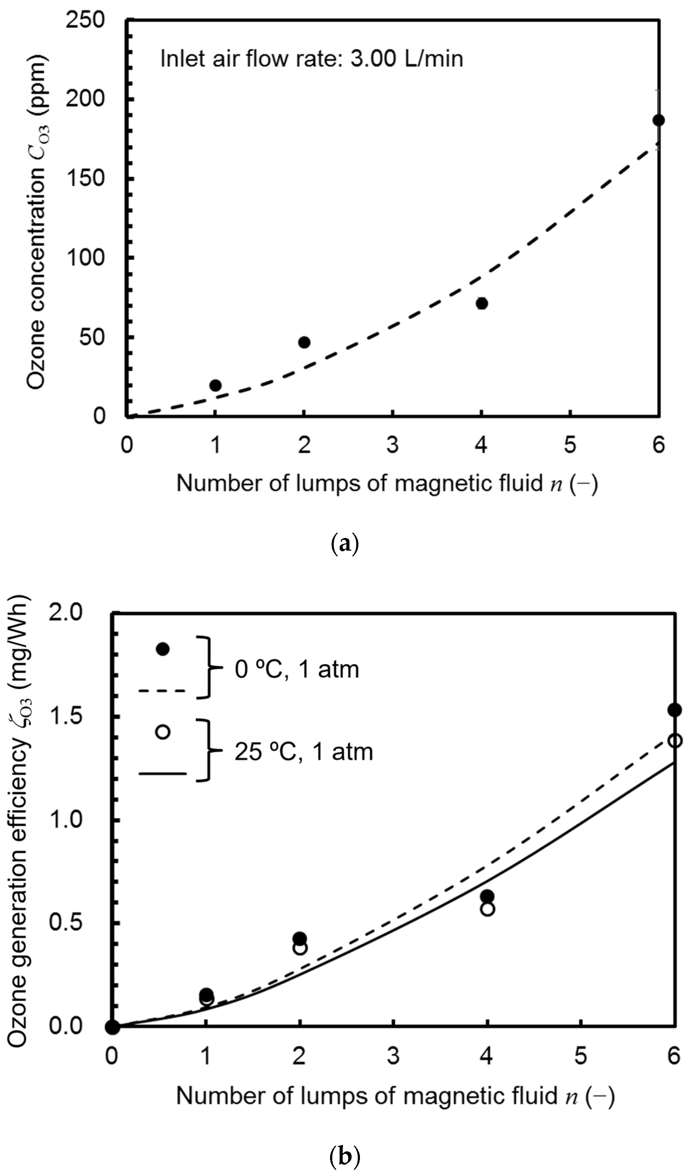
(2)
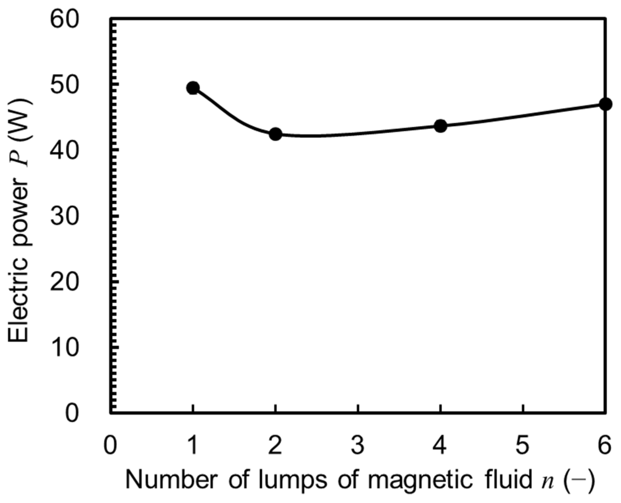
The power consumption of the magnetic fluid filter with NTP P and the generated O3 concentration CO3 are investigated for different numbers of lumps of the magnetic fluid n and the O3 generation efficiency ζO3 is calculated from these data. The results show that ζO3 increases proportionally with n. For 25 °C and 1 atm, the ζO3 values are 0.14, 0.39, 0.57, and 1.39 mg/Wh at n = 1, 2, 4, and 6, respectively.
(3)
Performance efficiency is improved in both PM collection and O3 generation with an increase in the number of lumps of magnetic fluid or with an increase in the number of spikes of the magnetic fluid with discharge. Namely, the hypothesis that an increase in spikes leads to improved collection efficiencies with energy conservation has been validated.
Although the collection of low-resistive PM using electrostatic forces proves challenging, the experimental data and analytical conclusions presented herein are expected to form the basis for future applications in air purification devices for PM (including low-resistive PM) without pressure loss. By revealing the relationship between the number of magnetic fluid spikes and collection efficiency as well as energy consumption and ozone generation efficiency in this study, it becomes possible to calculate the performance and determine the specifications of air purifiers that are tailored to the scale of air purification in future designs.

Author Contributions

Conceptualization, T.K.; Data curation, T.K. and Y.A.; Formal analysis, T.K.; Investigation, T.K. and Y.A.; Methodology, T.K. and Y.A.; Project administration, T.K.; Resources, T.K.; Software, T.K. and Y.A.; Supervision, T.K.; Validation, T.K. and Y.A.; Visualization, T.K. and Y.A.; Writing—original draft, T.K.; Writing—review and editing, Y.A. All authors have read and agreed to the published version of the manuscript.

Funding

This research did not receive any specific grant from funding agencies in the public, commercial, or not-for-profit sectors.

Data Availability Statement

Data are available on request due to restrictions.

Conflicts of Interest

The authors declare no conflicts of interest.

References

  1. Xu, S.C.; Zhou, Y.F.; Feng, C.; Zhang, J.N. The factors of regional PM2.5 emissions inequality in China. Process. Saf. Environ. Prot. 2021, 150, 79–92. [Google Scholar] [CrossRef]
  2. Karagulian, F.; Belis, C.A.; Dora, C.F.C.; Prüss-Ustün, A.M.; Bonjour, S.; Adair-Rohani, H.; Amann, M. Contributions to cities’ ambient particulate matter (PM): A systematic review of local source contributions at global level. Atmos. Environ. 2015, 120, 475–483. [Google Scholar] [CrossRef]
  3. Tian, E.; Xia, F.; Wu, J.; Zhang, Y.; Li, J.; Wang, H.; Mo, J. Electrostatic air filtration by multifunctional dielectric heterocaking filters with ultralow pressure drop. ACS Appl. Mater. Interfaces 2020, 12, 29383–29392. [Google Scholar] [CrossRef]
  4. Kim, H.J.; Han, B.; Kim, Y.J.; Yao, S.J. Characteristics of an electrostatic precipitator for submicron particles using non-metallic electrodes and collection plates. J. Aerosol Sci. 2010, 41, 987–997. [Google Scholar] [CrossRef]
  5. Mo, J.; Tian, E.; Pan, J. New electrostatic precipitator with dielectric coatings to efficiently and safely remove sub-micro particles in the building environment. Sustain. Cities Soc. 2020, 55, 102063. [Google Scholar] [CrossRef]
  6. Dong, H.; Zhang, Y.; Du, Q.; Gao, J.; Shang, Q.; Feng, D.; Huang, Y. Generation and emission characteristics of fine particles generated by power plant circulating fluidized bed boiler. Energies 2022, 15, 6892. [Google Scholar] [CrossRef]
  7. Popa, G.N.; Dinis, C.M.; Iagăr, A. Investigations on three-section plate-type electrostatic precipitators used in thermoelectric power plants. Energies 2023, 16, 1186. [Google Scholar] [CrossRef]
  8. Suhonen, H.; Laitinen, A.; Kortelainen, M.; Yli-Pirilä, P.; Koponen, H.; Tiitta, P.; Ihalainen, M.; Jokiniemi, J.; Suvanto, M.; Tissari, M.; et al. High temperature electrical charger to reduce particulate emissions from small biomass-fired boilers. Energies 2020, 14, 109. [Google Scholar] [CrossRef]
  9. Drga, J.; Holubčík, M.; Čajová Kantová, N.; Červenka, B. Design of a low-cost electrostatic precipitator to reduce particulate matter emissions from small heat sources. Energies 2022, 15, 4148. [Google Scholar] [CrossRef]
  10. Jidenko, N.; Borra, J.P. Self-cleaning, maintenance-free aerosol filter by non-thermal plasma at atmospheric pressure. J. Hazard. Mater. 2012, 235–236, 237–245. [Google Scholar] [CrossRef]
  11. Zhu, Y.; Tao, S.; Chen, C.; Liu, J.; Chen, M.; Shangguan, W. The experimental and simulation investigation of the dynamic characteristic of submicron-scale aerosol in high-voltage electric field by a visualization method. J. Hazard. Mater. 2021, 416, 126227. [Google Scholar] [CrossRef] [PubMed]
  12. Zhang, J.; Wang, J.; Jiang, Z.; Xu, D. Trapping PM2.5 particles from electrostatic precipitator equipped with magnetic field under different gas velocities. Process. Saf. Environ. Prot. 2022, 158, 115–122. [Google Scholar] [CrossRef]
  13. Yamamoto, T.; Mimura, T.; Otsuka, N.; Ito, Y.; Ehara, Y.; Zukeran, A. Diesel PM collection for marine and automobile emissions using EHD electrostatic precipitators. IEEE Trans. Ind. Appl. 2010, 46, 1606–1612. [Google Scholar] [CrossRef]
  14. Kuwahara, T. Fundamental characteristics of low-resistive particulate matter removal using a magnetic fluid and non-thermal plasma. J. Magn. Magn. Mater. 2020, 498, 166161. [Google Scholar] [CrossRef]
  15. Cheon, T.W.; Lee, J.Y.; Bae, J.Y.; Yook, S.J. Enhancement of collection efficiency of an inertial impactor using an additional punched impaction plate. Aerosol Air Qual. Res. 2017, 17, 2349–2357. [Google Scholar] [CrossRef]
  16. Cottrell, F.G. Art of Separating Suspended Particles from Gaseous Bodies. U.S. Patent 895729, 11 August 1908. [Google Scholar]
  17. Penney, G.W. A new electrostatic precipitator. Electr. Eng. 1937, 56, 159–163. [Google Scholar] [CrossRef]
  18. Davies, C.N. Definitive equations for the fluid resistance of spheres. Proc. Phys. Soc. 1945, 57, 259–270. [Google Scholar] [CrossRef]
  19. Allen, M.D.; Raabe, O.G. Slip correction measurements of spherical solid aerosol particles in an improved Millikan apparatus. Aerosol Sci. Technol. 1985, 4, 269–286. [Google Scholar] [CrossRef]
  20. Kim, J.H.; Mulholland, G.W.; Kukuck, S.R.; Pui, D.Y.H. Slip correction measurements of certified PSL nanoparticles using a nanometer differential mobility analyzer (Nano-DMA) for Knudsen number from 0.5 to 83. J. Res. Natl. Inst. Stand. Technol. 2005, 110, 31–54. [Google Scholar] [CrossRef]
  21. Einstein, A. Über die von der molekularkinetischen Theorie der Wärme geforderte Bewegung von in ruhenden Flüssigkeiten suspendierten Teilchen. Ann. Physik. 1905, 322, 549–560. [Google Scholar] [CrossRef]
  22. White, H.J. Particle charging in electrostatic precipitation. Trans. Am. Inst. Electr. Eng. 1951, 70, 1186–1191. [Google Scholar] [CrossRef]
  23. Intra, P.; Tippayawong, N. An overview of unipolar charger developments for nanoparticle charging. Aerosol Air Qual. Res. 2011, 11, 187–209. [Google Scholar] [CrossRef]
  24. Cowley, M.D.; Rosensweig, R.E. The interfacial stability of a ferromagnetic fluid. J. Fluid Mech. 1967, 30, 671–688. [Google Scholar] [CrossRef]
  25. Fukuda, Y.; Douhara, N. Study on interfacial phenomena of magnetic fluids. JSME Int. J. Ser. B 2005, 48, 735–742. [Google Scholar] [CrossRef]
  26. Uehara, S.; Itoga, T.; Nishiyama, H. Discharge and flow characteristics using magnetic fluid spikes for air pollution control. J. Phys. D Appl. Phys. 2015, 48, 282001. [Google Scholar] [CrossRef]
  27. Kuwahara, T. Reduction in energy consumption using fuel cells in non-thermal plasma-based water sterilization by bubbling ozone. IEEE Trans. Ind. Appl. 2018, 54, 6414–6421. [Google Scholar] [CrossRef]
  28. Tomiyasu, H.; Fukutomi, H.; Gordon, G. Kinetics and mechanism of ozone decomposition in basic aqueous solution. Inorg. Chem. 1985, 24, 2962–2966. [Google Scholar] [CrossRef]
  29. Buehler, R.E.; Staehelin, J.; Hoigné, J. Ozone decomposition in water studied by pulse radiolysis. 1. Perhydroxyl (HO2)/hyperoxide (O2) and HO3/O3 as intermediates. J. Phys. Chem. 1984, 88, 2560–2564. [Google Scholar] [CrossRef]
  30. Kuwahara, T.; Nishii, S.; Kuroki, T.; Okubo, M. Complete regeneration characteristics of diesel particulate filter using ozone injection. Appl. Energy. 2013, 111, 652–656. [Google Scholar] [CrossRef]
  31. Shi, Y.; He, Y.; Cai, Y.; Li, Z.; Wang, W.; Zhou, Y.; Lu, Y.; Yang, Y. Effect of nonthermal plasma with different ozone concentrations on the oxidation and removal of different components in particulate matter. J. Energy Inst. 2022, 102, 268–277. [Google Scholar] [CrossRef]
  32. de Castro, B.J.C.; Sartim, R.; Guerra, V.G.; Aguiar, M.L. Hybrid air filters: A review of the main equipment configurations and results. Process Saf. Environ. Prot. 2020, 144, 193–207. [Google Scholar] [CrossRef]
  33. Flagan, R.C.; Seinfeld, J.H. Fundamentals of Air Pollution Engineering; Prentice Hall: Upper Saddle River, NJ, USA, 1988; pp. 420–425. ISBN 0-13-332537-7. [Google Scholar]
  34. Choi, D.Y.; An, E.J.; Jung, S.H.; Song, D.K.; Oh, Y.S.; Lee, H.W.; Lee, H.M. Al-coated conductive fiber filters for high-efficiency electrostatic filtration: Effects of electrical and fiber structural properties. Sci. Rep. 2018, 8, 5747. [Google Scholar] [CrossRef] [PubMed]
Figure 1. Schematic of the working principle of a magnetic fluid filter with NTP discharge.
Energies 17 01865 g001
Figure 2. Schematic of the experimental setup and method used: (a) for evaluating the PM collection efficiency of the filter; (b) for measurement of O3 concentration.
Energies 17 01865 g002
Figure 3. Magnetic fluid filter with NTP. (a) Schematic with structure and dimensions. (b) Photograph.
Energies 17 01865 g003
Figure 4. Schematic depicting the arrangement of lumps of magnetic fluid in the filter at n = 1, 2, 4, and 6.
Energies 17 01865 g004
Figure 5. Experimental results of PM collection efficiencies in the magnetic fluid filter: (a) without NTP ηMF; (b) with NTP ηMFNTP.
Energies 17 01865 g005
Figure 6. Calculation results based on the migration velocity equations. (a) Relationship between PM diameter and migration velocities for different transport mechanisms. (b) Time for PM to travel 2 mm due to electrostatic forces for different PM diameters.
Energies 17 01865 g006
Figure 7. Relationship between the number of lumps of magnetic fluid n and the pressure loss across the magnetic fluid filter Δp for an inlet air flow rate of Qin = 2.83 L/min.
Energies 17 01865 g007
Figure 8. Relationship between the number of lumps of magnetic fluid n and the power consumption associated with the discharge P.
Energies 17 01865 g008
Figure 9. O3 generation in the magnetic fluid filter with NTP. (a) Relationship between the number of lumps of magnetic fluid n and the generated O3 concentration CO3 with an inlet air flow rate of Qin = 3.00 L/min. (b) Relationship between the number of lumps of magnetic fluid n and the O3 generation efficiency ζO3.
Energies 17 01865 g009
Disclaimer/Publisher’s Note: The statements, opinions and data contained in all publications are solely those of the individual author(s) and contributor(s) and not of MDPI and/or the editor(s). MDPI and/or the editor(s) disclaim responsibility for any injury to people or property resulting from any ideas, methods, instructions or products referred to in the content.

