Article

Numerical Research on Flow Characteristics at High Radii of Rim Seals with Different Geometric Structures

Depratment of Energy and Power Engineering, Tsinghua University, Beijing 10084, China
*
Author to whom correspondence should be addressed.
Energies 2024, 17(8), 1877; https://doi.org/10.3390/en17081877
Submission received: 1 February 2024 / Revised: 27 March 2024 / Accepted: 10 April 2024 / Published: 15 April 2024
(This article belongs to the Section J1: Heat and Mass Transfer)

Abstract

:
In the high-temperature mainstream of gas turbines, there is a rim clearance between the rotor and the stator. A rim seal is to prevent the intrusion of high-temperature gas by spraying cool fluid from the inside of the rim clearance to the outside. In the past research on rim seals, the focus was on the overall performance of the sealing structure, and the flow in the disc cavity was studied more, but the high-radius flow was simplified. In recent years, additional research in the field has focused on more complex sealing structures and high-radius flows, such as the interface between the disk cavity and the mainstream. There is more work to be conducted in this area of research. In this paper, the unsteady numerical simulation of the flow in four different rim sealing geometries is carried out by the URANS method. The flow phenomena and the influence of geometry on the flow are studied. The numerical simulation results are validated with the experimental results. It is found that the fluid in the rim sealing obviously presents two distinct forms and confrontations according to the tangential velocity. The flow in the sealing structure presents obvious circumferential non-uniformity. Compared with the single-axial structure, in the single-radial structure, the mixing area is induced by the radial geometry, and more vortex structures are generated, the mixing process is more intense, and the sealing effect is better. In the double-sealing structure, the inner structure plays the role of a barrier, and the cavity geometry between the two layers has a major influence on the sealing performance.

1. Introduction

The continuous pursuit of increasing efficiency regarding current gas turbines results in the increasing initial temperature of turbines. The current more advanced H-class gas turbine temperature reaches 1430 °C to 1600 °C. The increase in turbine temperature provides great challenges to turbine materials and turbine cooling technology. In the mainstream of the high-temperature turbine cascade, there is a rim clearance between the rotor and the stator. A rim seal is to prevent the intrusion of high-temperature gas by spraying cool fluid from the inside of the rim clearance to the outside. The rim seal is located at the junction of the secondary air system of the gas turbine and the mainstream of the turbine. The form of rim seal is that the coolant air purge process through the rim clearance between the rotor and stator. The rim seal can block the ingress of the mainstream high-temperature gas, and can also cool the end wall of the mainstream.
Research on rim seals has been in progress for decades. The early research mainly focused on the cavity location at a low radius. As early as 1951, Batchelor [1] and Stewartson [2] proposed two classical disk cavity flow models based on the classical free disk flow theory. Mellor [3] demonstrated numerically that there are multiple possibilities for the flow structure in the cavity. Daily and Nece [4] systematically divided the flow state in the closed rotor–stator cavity into different regions according to the rotational Reynolds number and the disc cavity spacing ratio.
In recent years, studies on the flow at high radii of complex sealing structures have become more and more common. Rabs [5] pointed out in 2009 that the K–H vortices generated by the circumferential velocity difference between two fluid flows exist at high radii. In 2017, Savov [6] studied the radial sealing structure of an inclined outlet and pointed out that the inclined outlet would lead to the existence of a reflux zone. Lian [7] analyzed the flow at the high radii of three sealing structures in 2020 and pointed out that the radial sealing clearance had limited blocking effects regarding the mainstream ingress flow when the purge flowrate was low, and this situation was improved after the internal sealing ring structure was installed. There are still many gaps in the understanding of flow mixing at high radii of complex structures, which necessitates further research.
Scholars are also concerned about the sealing performance of the rim sealing structure. Bayley [8] studied the sealing problem with no mainstream in 1970 and obtained the minimum sealing flow correlations, which was an earlier study on the sealing problem. Then, Dadkhah [9] studied the sealing problem with a uniform mainstream in 1992 and achieved the distribution of sealing efficiency along the axis direction. Phadke and Owen et al. [10] studied the problem of an uneven mainstream in 1988 and pointed out the influence of a circumferential peak–valley difference regarding the mainstream pressure on the ingress. In 2009, Owen [11,12] summarized previous studies, simplified the interaction process between the ingress and egress fluid, and extracted a one-dimensional orifice model. These studies examined the sealing performance of the sealing structure as a whole and serve to initiate further examination of the influence caused by the mainstream effect.
On the other hand, in order to achieve a better sealing effect, the structure of rim sealing has been constantly developing from simple to complex. In 1988, Phadke and Owen [13] studied seven sealing structures with different complexity levels, including a radial sealing structure and an axial sealing structure, and obtained the correlations of the minimum sealing flow. In 2012, Popovic and Howard et al. [14] studied the characteristics of the same sealing structure by altering the parameters of its geometry. Subsequently, Mi-Ae Moon [15] added a fin based on this Ivan geometry, and the results showed that the fin could significantly block the ingress fluid. In 2016, based on the sealing characteristics of the sealing structure, Liu et al. [16] designed a cylindrical bulge on the inner side of the sealing structure to create the circumferential pressure non-uniformity of the inner cavity, and they comprehensively evaluated its performance.
With the continuous improvement of the performance of rim seals, the sealing structure inevitably becomes more complex, and the influence of the flow phenomenon at a high radius on the sealing performance becomes more and more important. It is necessary to further study the mechanisms of ingress and flow in sealing structures at high radii in addition to clarifying the relationship between them for improving the performance of rim seals. In this paper, four sealing structures with different geometries were selected as research objects, and the URANS numerical simulation method validated by experimental data was used to study the flow phenomenon in rim seals (especially in the higher radius of the rim seal cavity near the rim clearance).
In general, the flow analysis and model summary regarding the rim clearance of the single-layer axial sealing structure are first carried out in detail in this paper, followed by the corresponding analyses of the other three sealing structures, and finally the differences between the flow and sealing of the three sealing structures are compared.

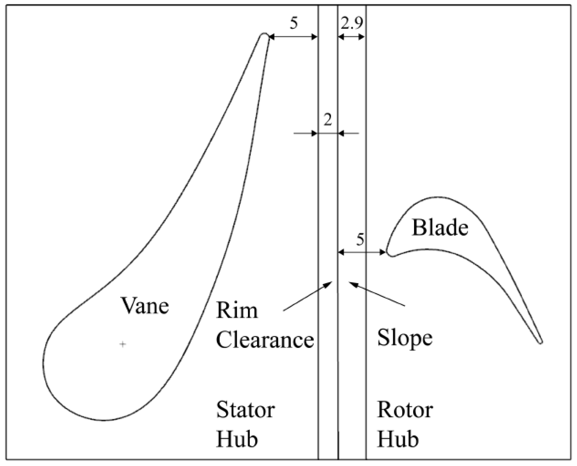
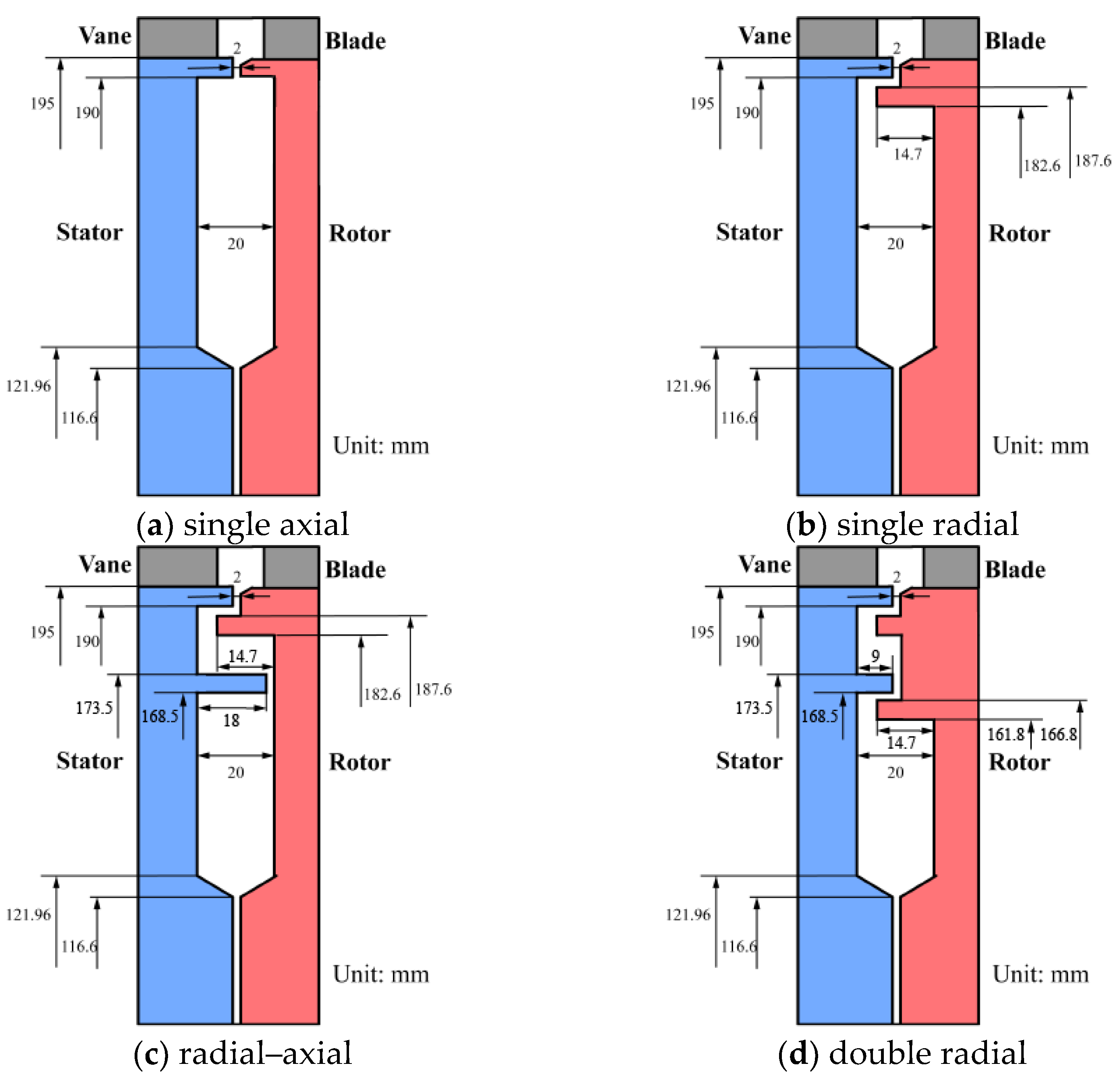
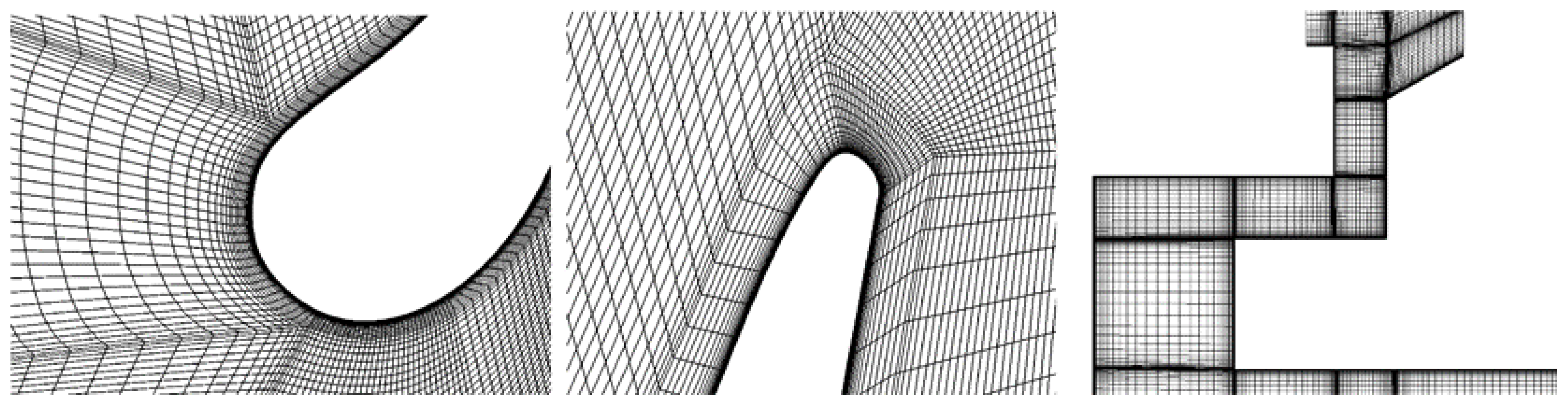
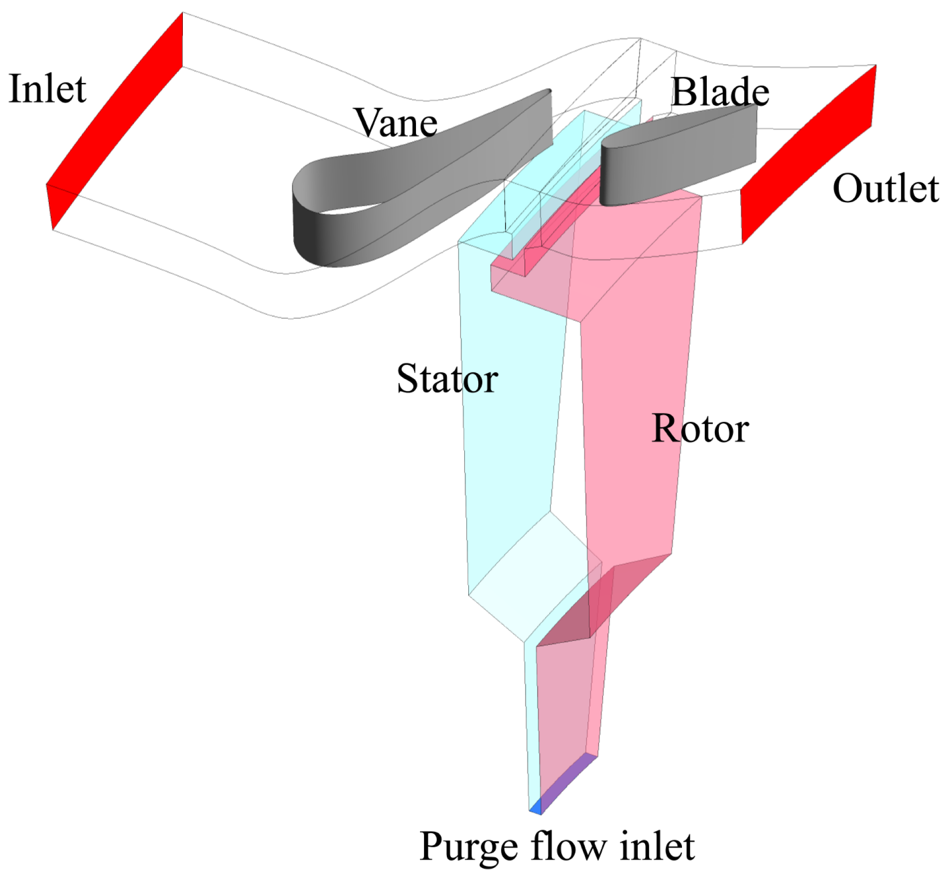
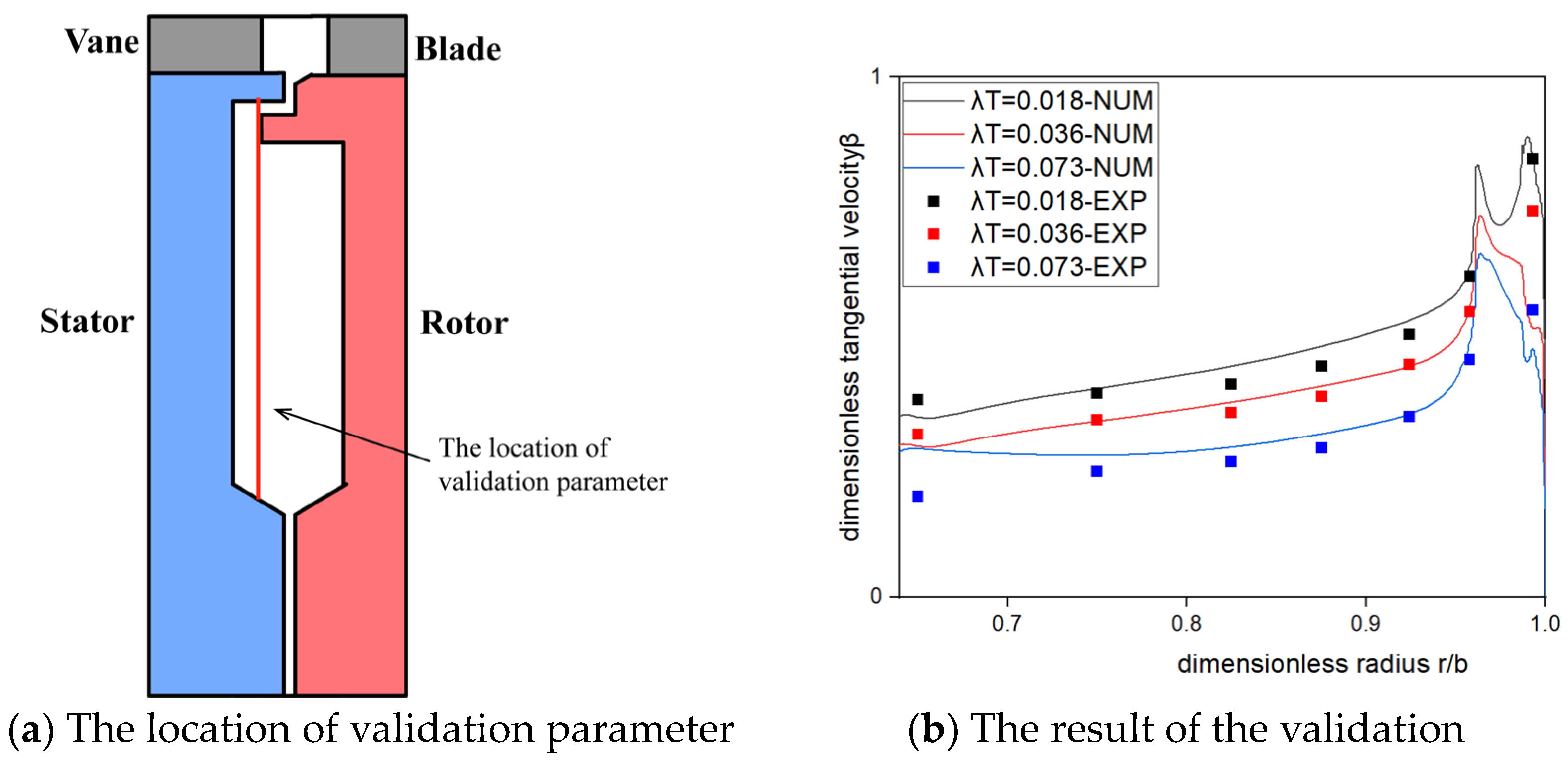
2. Computational Methods

The research object of this paper is the fluid domain of the rim seal containing the one-stage rotor–stator cavity in the gas turbine, which includes the mainstream with vanes and blades and the rotor–stator cavity. There are 32 vanes and 32 blades in the cascade. The vane and blade profile is shown in Figure 1, and the height of them is 10 mm.
The sealing structure includes four different geometries, namely single-axial, single-radial, radial–axial, and double-radial structures, as shown in Figure 2.
The key geometric parameters of the whole structure are shown in Table 1.
The main research method in this paper is CFD numerical simulation, the numerical method is URANS, the solver is ANSYS FLUENT, and the turbulence model is Transition-SST. Considering that the whole cycle simulation of this fluid domain consumes a great deal of computing resources, the computational geometry adopted in this paper is 1/32 circumference (11.25°), including one blade and one vane, as shown in Figure 3. Periodic boundary conditions are adopted in the circumferential direction.
Other boundary conditions in Table 2 include mainstream inlet, mainstream outlet, purge flow inlet, and rotor–stator surface. The mainstream inlet is set as mass flow inlet; the mainstream outlet is set as pressure outlet; and the purge flow inlet is set as velocity inlet. Wu [17] was referred to in setting the rotating and static solution domain, which included the static solution domain for the vane part, and the rotating solution domain (the rotating speed is 3000 rpm) for the blade part and the cavity part. The dividing line between the two was 1 mm upstream of the rim clearance. In the rotating solution domain, the rotor surface is set as static no-clip wall referring to the adjacent zone. In the static solution domain, the stator surface is set as rotating wall (rotating speed is −3000 rpm) referring to the adjacent zone.
Supplementary statement: In the division of fluid domain, the static vane region is set as the static solution domain, the moving blade region is set as the mesh rotation solution domain, and the clearance region and the cavity region between the stator and rotor are set as the frame rotation solution domain.
The setting of the time step refers to the setting of Wang [18], and 1/40 of the period of the blade (that is, the time for the rotor to rotate a blade cascade distance) is adopted as the time step. In this study, the value of time step is 1.5625 × 10⁻⁵ s. After validation, the number of internal iteration steps is 100, which can simultaneously take into account the efficiency and accuracy. Before the unsteady calculation, the flow field value is obtained by the steady calculation first, and then the value is used as the initial value of the unsteady flow field, which can effectively reduce the cost of computing power resources.
Considering that the flow conditions involved in the study include the flow in the cascade, the flow in the rim seal cavity, and the flow in the rim clearance, which is relatively complex, the mesh used in this study is a structured grid and the area near the wall is densified. In order to ensure the accuracy of the simulation of near-wall turbulence using the SST model, after several iterations, the value of y+ near the wall is about 1. The details of the grid are shown in Figure 4.
It should be especially mentioned that the numerical means used in this study are all the options provided by the commercial software FLUENT 2019v1, and no self-written UDF is used.
The experimental validation of the simulation results of the CFD method in this paper is carried out by comparing with the experimental results in Wu [17]. The experimental results were mainly completed by Wu on a one-stage rim sealing test rig with mainstream cascades at the University of Bath, UK. The numerical model in this paper is basically consistent with the geometry of the test rig.
The comparison parameter is the tangential velocity ratio β, which is the dimensionless tangential velocity, calculated by the formula β = v/vr, where v is the local tangential velocity and vr is the local rotor tangential velocity. Because the rotation speed of the mainstream is high and the rotation speed of the inner cavity is low, this parameter can represent the degree of ingress there. The location of the selected parameters is in the cavity of the single-radial sealing structure shown in Figure 5a.
The parameter λT in Figure 5 represents the flow state inside the rotor–stator cavity, which is defined as
λ T = C w / R e φ 0.8
The parameter Cw is the dimensionless secondary purge flowrate, which is defined as
C w = m / μ b
The m is the secondary purge flowrate, the μ is the dynamic viscosity coefficient of the fluid, and the b is the max radius of the cavity. The ρ is the density of the fluid. The Ω is the rotating speed of the rotor.
The parameter Reφ is the rotational Reynolds number, which is defined as
R e φ = ρ Ω b 2 / μ
As can be seen from Figure 5b, under the three different flow conditions, the β values of the experimental results and the numerical simulation results are in good agreement in most of the positions, both in terms of trend and numerical value, which is reliable for the numerical simulation of the phenomenon. The simulation results can be used in the analysis and discussion of the following research.

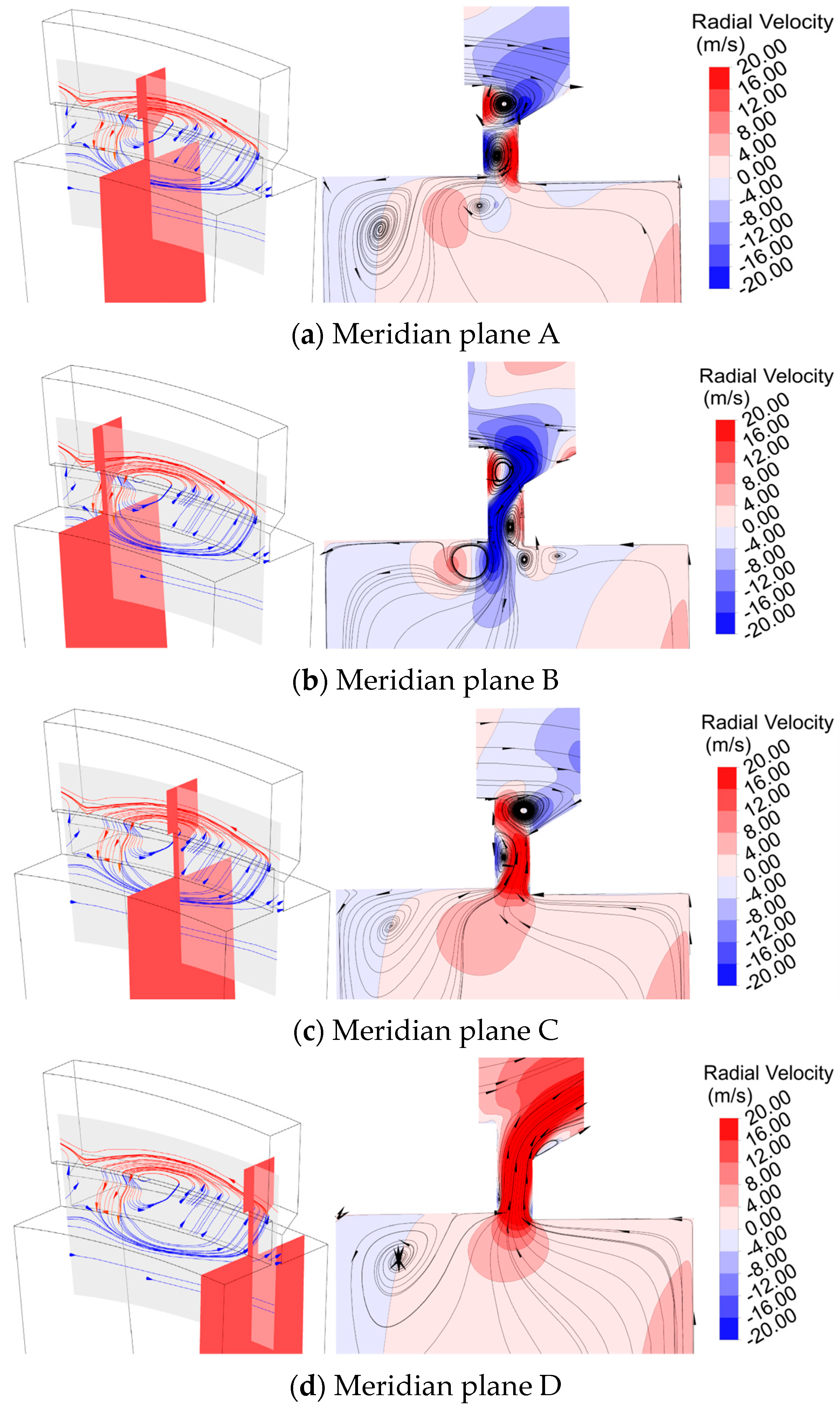
3. Results and Discussion

The numerical study of ingress–egress phenomena and flow characteristics at high radii is carried out for four representative sealing geometry structures that have been simplified geometrically. They are single-axial sealing, single-radial sealing, radial–axial sealing, and double-radial sealing. The specific geometry is provided in the section on computational methods.
In this paper, the research on the sealing structure mainly focuses on high radii. The flow situation here is relatively complex; there are both ingress fluid from the mainstream and egress fluid from the low radius of the disc cavity, both of which involve shear and mixing flow in the sealing structure. The interaction between the two is most intense at the junction of the sealing structure and the mainstream. Therefore, in different sealing structures, some surfaces are selected to observe the flow structure on them.
Previous studies have shown that the unsteady effects caused by blade sweeping are more pronounced at a high radius. Therefore, the unsteady numerical simulation results by URANS in a sealing structure can be time-averaged and processed within two blade periods (that is, 80 time steps) to obtain the results that can reflect the steady flow characteristics and are not affected by the sweeping motion of the blades in the mainstream.

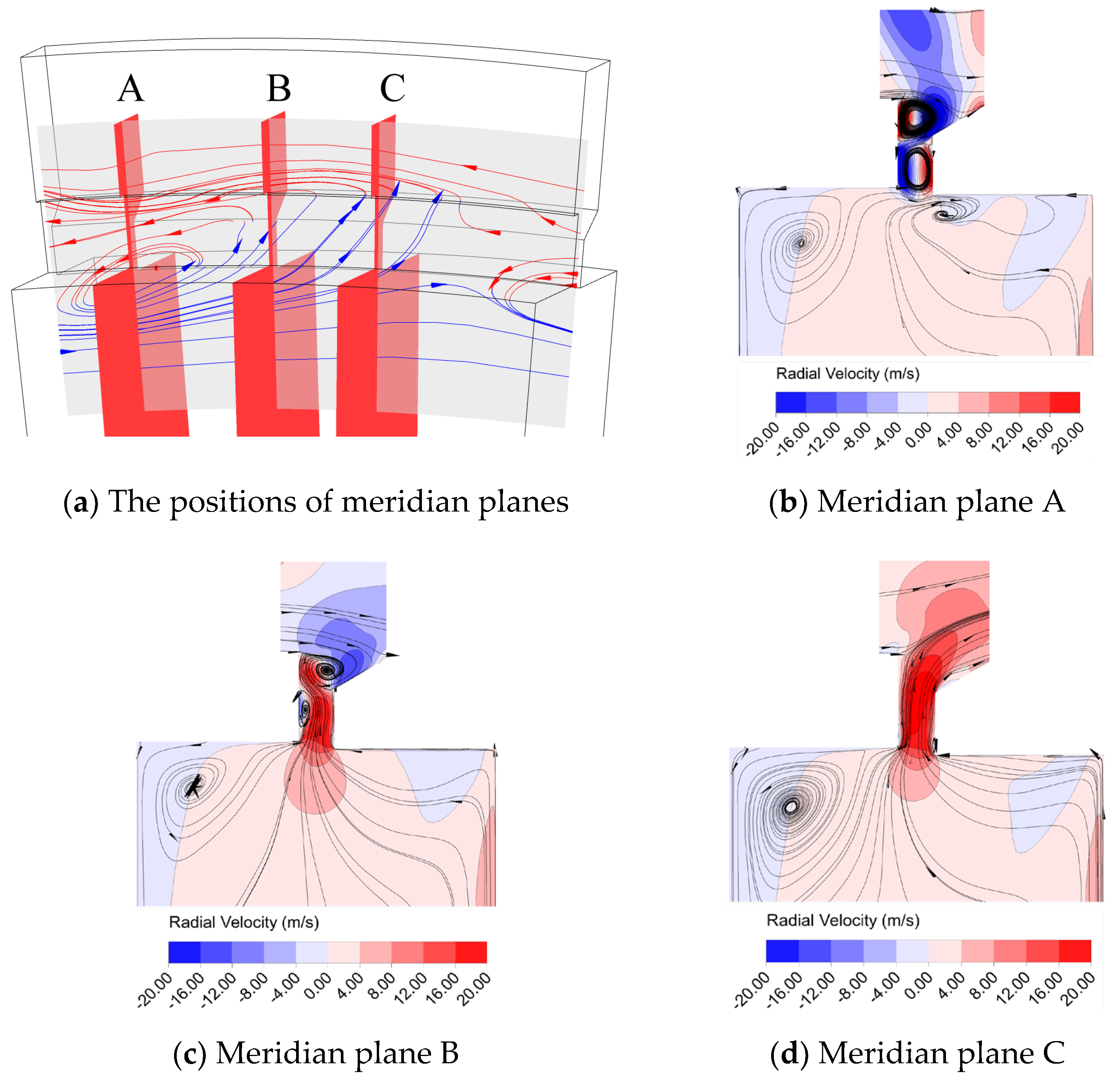
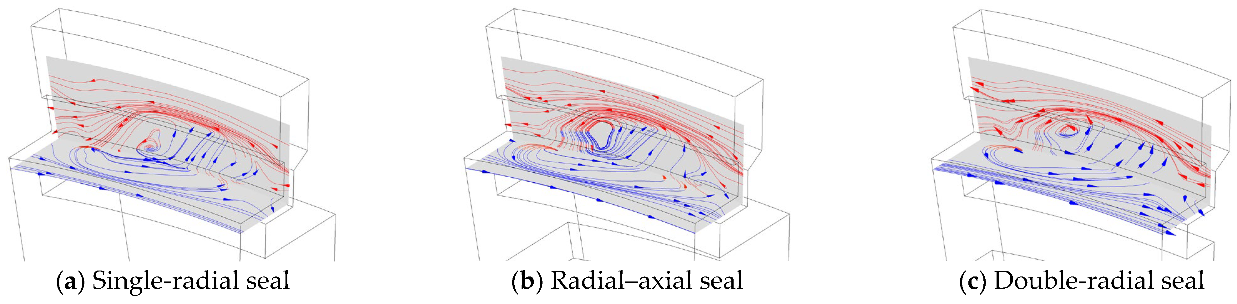
3.1. The Flow Characteristics of the Single-Layer Sealing Structure

3.1.1. The Flow Characteristics of the Single-Axial Sealing Structure

In the flow at a high radius, it is an important problem to define the ingress fluid and the egress fluid, and this part of the problem can be referred to in terms of the author’s previous research [19]. The ingress fluid comes from a high radius and commonly has a higher dimensionless tangential velocity β, while the egress fluid has a lower dimensionless tangential velocity. Therefore, β = 1 can be used as the threshold to distinguish the ingress fluid from the egress fluid. In the process of shearing and mixing, the β value is then averaged to a certain extent.
An intuitive understanding of the flow at the high radius of the single-axial seal can be obtained from the streamline diagram at different flows in Figure 6, where the red lines in the figure refer to the ingress fluid with high tangential velocity and the blue lines refer to the egress fluid with low tangential velocity.
As can be seen in Figure 6, in the sealing structure between the mainstream and the sealing cavity, there is a flow structure in which the ingress fluid and the egress fluid are mixing. The distribution of the flow structure in the circumferential direction almost occupies the entire sealing structure. Inside and outside the rim clearance are mainly the mainstream fluid with high tangential velocity and the cavity fluid with low tangential velocity, while the interaction between the ingress and egress flow mainly occurs in the rim clearance. When two fluids with opposite velocities are mixed, a high-pressure region is generated. Under the action of the high-pressure region, the two fluids deflect, and one part of the ingress fluid remerges into the mainstream, while the other part deflects into the low radius region. Part of the egress fluid returns to the low-radius region, while the other part of the egress fluid merges into the mainstream and rapidly changes velocity direction under the strong influence of the mainstream. When the flowrate is low (Figure 6b), the intrusion depth of the ingress fluid in the radial direction is deeper at the position of the higher external mainstream pressure. When the flowrate increases, the intrusion depth decreases and the deflection angle of the fluid increases. The position of the flow structure also changes under the action of a purge flow fluid with a high flowrate (the overall radial velocity is outward and the circumferential velocity is low). It is lifted in the radial direction and dragged along the opposite direction of the rotor rotation in the circumferential direction, and the corresponding translation occurs.
In fact, when the purge flowrate is 0 (as shown in Figure 6a), such a flow structure still exists in the rim clearance, at which time there is no egress fluid out, and the deflection angle of the ingress fluid is very small. This proves that the flow structure is not caused by the purge flow but is more likely to be induced by the uneven distribution of the circumferential pressure of the mainstream and the K–H instability of the two fluids with a tangential velocity difference. The increased purge flowrate plays an exciting role in the flow structure, making it more intense and obvious, and finally leading to the generation of an ordered flow structure.
The flow mechanism can be further analyzed by observing the streamline of the flow structure under each flowrate by selecting the representative meridian plane of different circumferential positions. This is shown in Figure 7.
When the flowrate is large (λT = 0.189), according to the flow structure distribution in Figure 6, the meridian plane at each position shown in Figure 7 is selected to further observe the flow structure. It can be seen that there are two obvious vortex systems distributed up and down in the rim clearance of plane A, and their rotation directions are opposite. The two vortex systems occupy the entire rim clearance, and there are fewer direct inflow and outflow streamlines. However, in plane B, the rotating vortex system is small and does not occupy the entire rim clearance. The vortex at the lower radius is close to the stator, and there is an inflow channel of ingress fluid on the side of the rotor. In plane C, the rotating vortex system is also small. The difference is that the vortex at a lower radius is close to the rotor, while there is an outflow channel of egress fluid on the side of the stator. However, in plane D, the vortex structure in the rim clearance is not obvious, and the egress fluid is mainly outward in this area. Under the rim clearance, there are vortex system structures with different sizes. Among them, in the plane where there is an inflow channel of the ingress fluid, there is a backflow vortex beside the stator at a high radius due to the fluid flow from the stator to the rotor in the mainstream and the structure of the sudden expansion at the junction of the cavity and the mainstream. The vortex system also exists on the side of the moving disk because of the flow and the intrusion fluid in the moving disk cavity.
When the flowrate is low (λT = 0.063), as shown in Figure 8, similar planes are also selected to observe the streamline and radial velocity distribution, and it can be seen that the flow is similar to that in the case of high flowrate. The difference is that, when the flowrate is low, the absolute value of the radial velocity is smaller than that in the case of a high flowrate regardless of the ingress fluid or egress fluid.
Through the above flow analysis, the circumferential region in the rim clearance can be divided into two regions: the interaction region and the outflow region. Among them, there are two vortex structure belts in the interaction region (as shown in Figure 9), and the outflow and inflow channels in this region are located in the crevice between the vortex system. The outflow area is mainly the area where the fluid flows out directly, and there are few vortex structures.
At a purge flowrate of 0, there is no purge flow. However, as shown in Figure 10, a similar structure still exists in the clearance except that the radial velocity in the outflow region is much smaller. Ingress and egress are still present. This is enough to prove that the reason for the formation of the vortex structure belt is not the purge flow, but the more direct reason is that the mainstream fluid forms a reflux region after the ingress regarding the rim clearance, and then it evolves into two vortex structure belts distributed up and down in the limited space with typical rim clearance.
The flow mode in the rim clearance can be viewed more intuitively by observing the three-dimensional streamline. Figure 11 shows the streamline of the purge flow fluid flowing outward at a lower flowrate (λT = 0.063). It can be seen that a more typical flow structure in the rim clearance exists at a lower mainstream pressure where the egress fluid flows directly out, while, at a higher mainstream pressure, the egress fluid stays in the interaction zone within the rim clearance and mixes with the ingress fluid. Then, there are two vortex systems distributed up and down.
The basic flow modes can be obtained from the above. In the circumferential distribution, there is a flow structure formed by the interaction between the purge flow and the mainstream flow. Inside and outside the rim gap, there are two flows with relatively parallel velocity directions, namely the purge fluid and the mainstream fluid. According to the flow conditions shown by the streamlines on the meridian plane, direct mainstream ingress occurs in the area with high mainstream pressure. Because the mainstream has a certain axial velocity component and a “step” structure, there is a backflow area at the junction of the rim clearance and the mainstream, and then, in the restricted clearance area, the vortex structure belt with opposite rotation directions evolves. There are outflow and inflow channels in the crevice between the vortices. In the lower mainstream pressure area, there is an outflow area of egress fluid, and some of the egress fluid at the edge of the outflow area is squeezed into the vortex structure belt zone in the rim clearance to participate in the mixing process due to the increase in mainstream pressure.

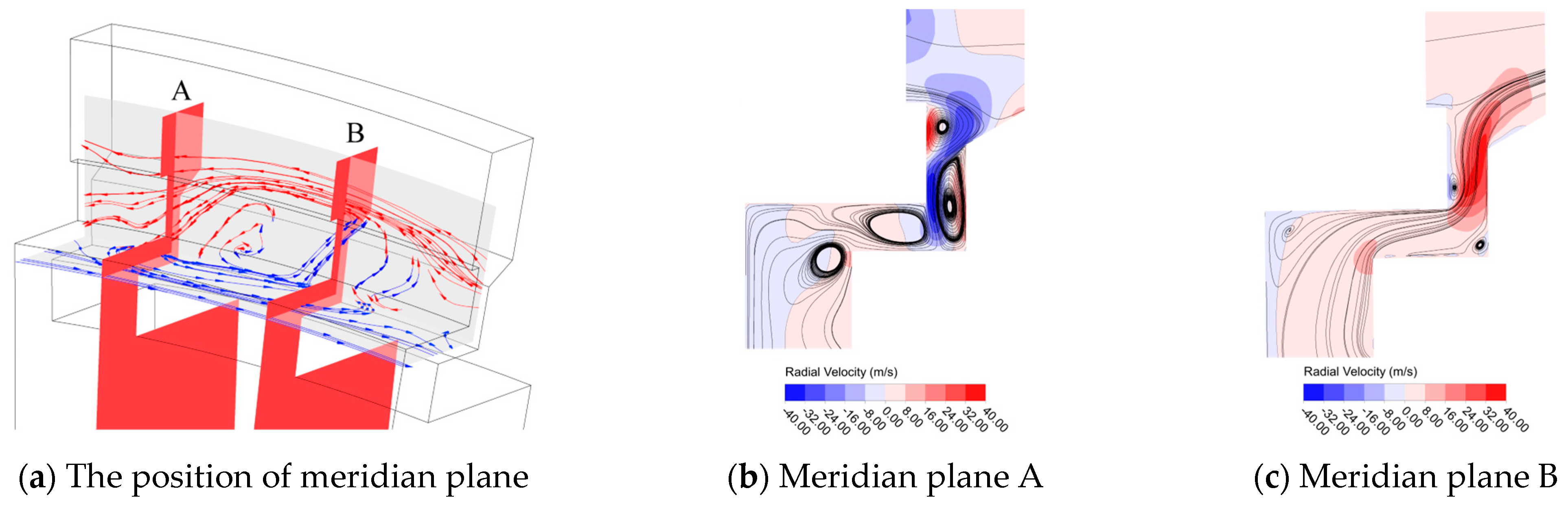
3.1.2. The Flow Characteristics of the Single-Radial Sealing Structure

The result of the single-radial sealing shown in Figure 12 is similar to that of the single-axial sealing: there is a flow structure formed by the interaction between the ingress fluid and the egress fluid, and, with an increase in the flowrate, the depth of the ingress fluid dive into the sealing structure becomes smaller and the deflection angle becomes larger. Different from the axial sealing results, the flow structure does not shift significantly in the circumferential position as the flowrate increases, and the ingress depth of the mainstream (the red part of the streamline) is smaller under the same flowrate. Due to the radial sealing geometry, the flow structure that should have descended deeper is blocked at the corner, the ordered structure is actually destroyed, and the complete flow structure is divided into two parts.
In the single-radial sealing structure, when the flow parameter is 0.063, the streamline analysis is carried out on several meridian planes. As shown in Figure 13, the inflow channel is shown in plane A, originally in the axial structure, and the backflow vortex on the side of the stator under the axial rim clearance is lifted and squeezed by the radial baffle, occupying the entire radial clearance. In the outflow area shown in plane B, due to the direction of the outflow fluid, it is affected by the radial structure, the flow incoming direction biases the side of the stator, and the corner of the entry axial clearance increases. Therefore, a backflow vortex appears on the side of the stator above the corner, which will further increase the strength of the backflow vortex in the flow channel. In conclusion, the vortex system generated by the above changes and other small vortex systems generated by the radial structure geometry further strengthen the interaction between the ingress fluid and the egress fluid at a high radius, resulting in a better sealing effect. Under the same flowrate, the tangential velocity at a high radius is higher, and the tangential position at a low radius is lower, reflecting a better barrier effect regarding the mainstream gas.

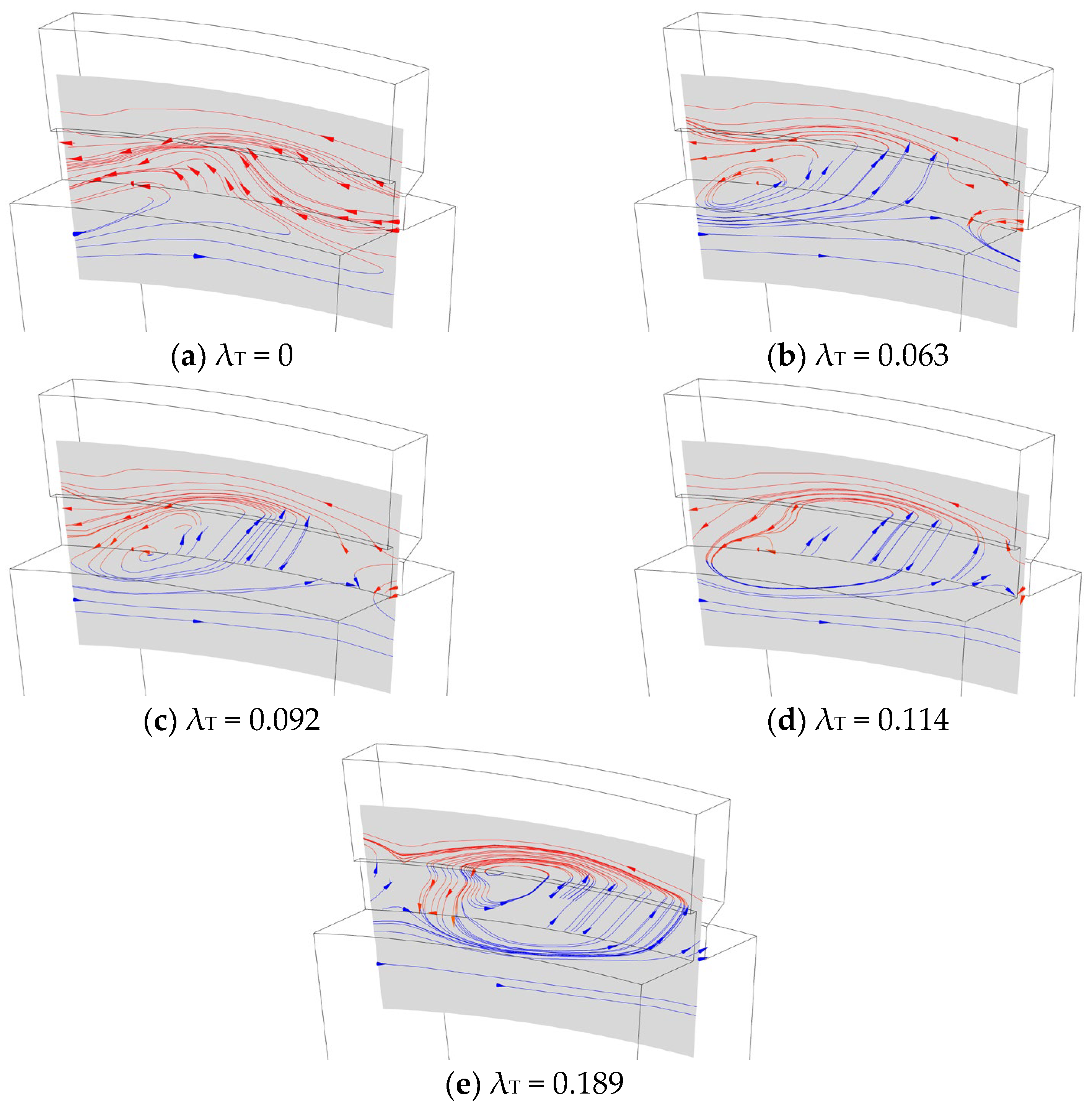
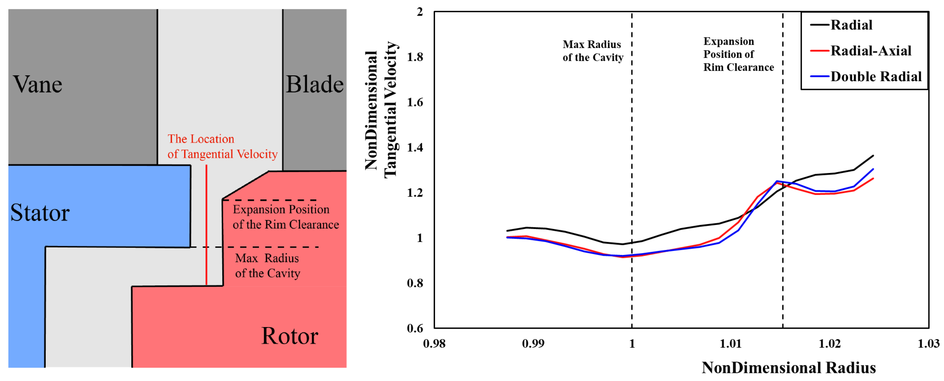
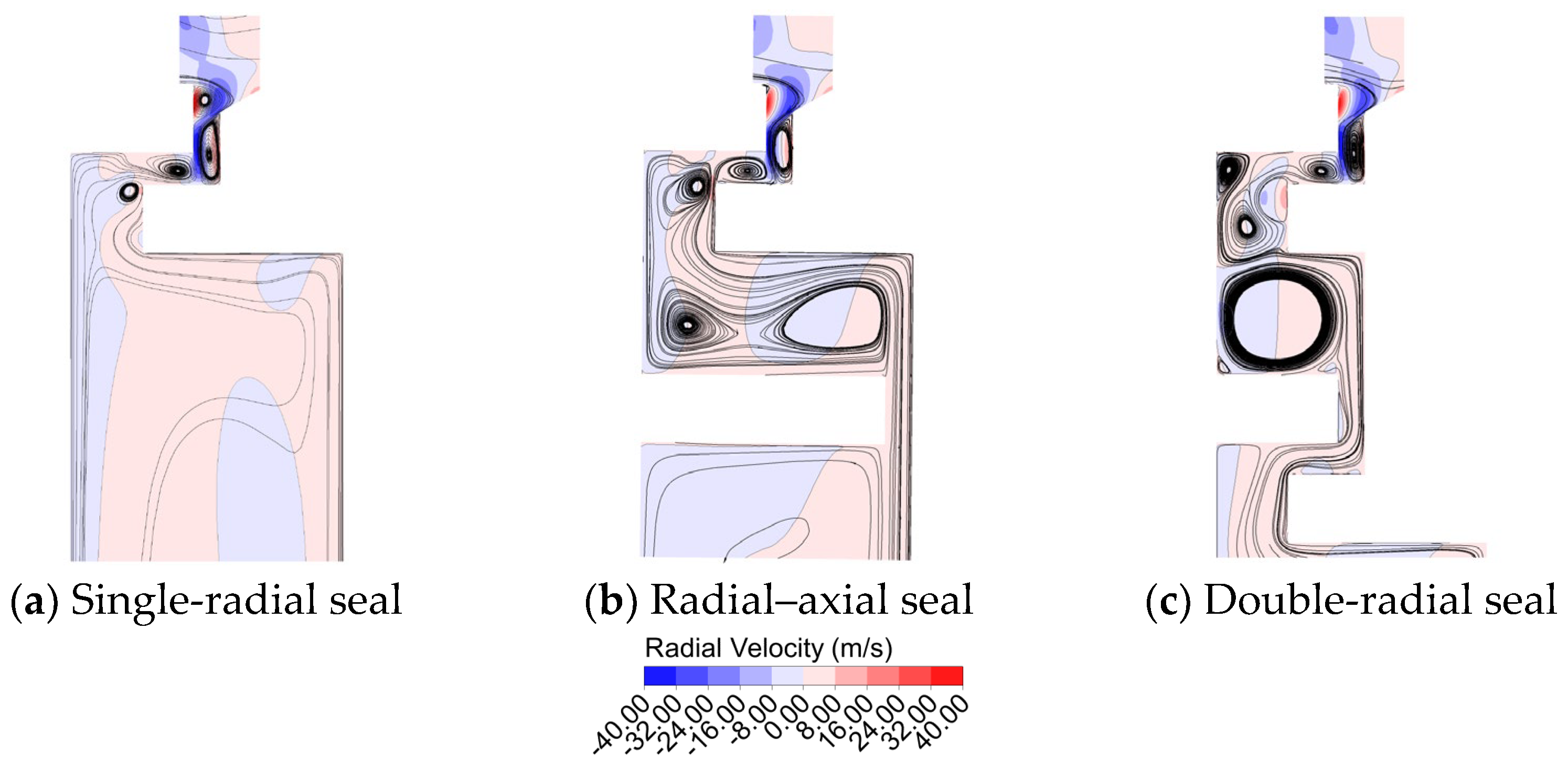
3.2. The Flow Characteristics of the Double-Layer Sealing Structure

The flow characteristics of the single-layer sealing and double-layer sealing structures are compared below. Figure 14 shows the comparison of the streamlines at high radii of a single-radial structure, a radial–axial sealing structure, and a double-radial sealing structure when the flow parameter λT = 0.063. Indeed, compared with the single-layer structure, the circumferential position of the flow structure is not much different, but the deflection angle of the inflow direction is larger. This indicates that the ingress fluid interacts more strongly with the egress fluid in the sealing structure and is more blocked. The difference in the flow structure is not obvious in the comparison between the double-radial sealing structure and the radial–axial sealing structure.
The relationship between flow characteristics and sealing characteristics can be better explained by comparing the dimensionless tangential velocity β values under different sealing geometry conditions. As the circumferential inhomogeneity at a high radius is more significant, the circumferential average operation is performed on the β values at high radii of the three structures to obtain the results shown in Figure 15. Indeed, the β value of the double-layer sealing structure is lower than that of the single-layer structure on the whole, and the sealing effect is better, but the β value of the double-layer structure is slightly higher than that of the single-layer structure near the expansion of the rim clearance. There are only slight differences between the radial–axial seal and double-radial seal.
Figure 16 shows the partial cavity streamlines and radial velocity distributions of single-radial sealing, radial–axial sealing, and double-radial sealing when the flow parameter λT = 0.063. It can be seen that the distributions of the three vortex systems in the outermost layer are basically the same due to the influence of the radial sealing geometry. In the inner layer structure, the purge flow fluid flows into the sealing structure by the rotor side. On account of the different sizes and shapes of the cavities of the different sealing structures, the vortex structure at the same radius shows different morphology, and the sealing characteristics are different due to the different interactions between the ingress and egress fluid in the different vortex structures.
As can be seen from the comparison of the β values regarding the different sealing geometries in Figure 17, the double-layer sealing structure has a lower β value and better sealing performance than the single-layer structure in the whole cavity due to the existence of the inner sealing ring. The emphasis of the two sealing structures is different. The radial–axial sealing structure has a lower β value in the region within the inner sealing ring, while the β value is the same as that of the single-layer structure outside the inner sealing ring. For the double-radial sealing structure, the β value inside the inner sealing ring is slightly higher than that in the radial–axial sealing structure, and the peak of the β value outside the inner sealing ring is significantly reduced.
The reason for the above difference is mainly the size and shape of the cavity between the inner and outer sealing rings. The cavity provides a place for internal and external fluid mixing, and it plays a role of as a barrier and buffer. The cavity volume of the radial–axial sealing structure is large, so the distribution of the β value at the higher radius of this part is not much different from that of the single-radial structure; the difference is that the strong barrier effect of the inner sealing ring leads to a more significant decline in the β value at lower radii. Due to the small volume of the cavity between the two layers of the double-radial sealing structure, the vortex system structure is squeezed into a smaller area, and the mixing effect in the limited area is more intense. Therefore, the peak of the β value caused by the sealing structure attached to the rotor is flattened, and the β value in the cavity shows a “ladder-like” distribution with the change in the cavity geometry.

4. Conclusions

In this paper, the flow characteristics and sealing mechanism at high radii of rim seals were studied by using the numerical simulation method validated by the experimental results for four different rim sealing geometric structures, and the following conclusions were reached.
At the junction between the sealing structure and the mainstream, the flow structure is induced by the non-uniformity of the mainstream circumferential pressure and the rim clearance geometry. The flow here takes on different forms under the excitation of different flow-sealed fluids. According to the different circumferential positions, an interaction area and an outflow area are included in the rim clearance. There are two vortex structure belts in the interaction area, and there are inflow and outflow channels between the vortex structures. There are few vortex structures in the outflow area, which is mainly the area where the purge flow is outward. This part analyzes the flow structure existing in the clearance of a simple single-axial sealing structure, which generally exists in a variety of sealing structures. The work in this part can provide a reference for the intrusion prevention work of key locations of rim sealing in engineering on the principle level.
For the single-radial structure, the flow structure inside and outside the rim clearance is more similar to that of the single-axial structure. The difference is that the radial clearance and the folding structure cause the flow structure to be squeezed, resulting in more vortex structures, which intensifies the mixing effect, thus enhancing the sealing effect of the sealing structure. This part focuses on the analysis of the principle of the performance improvement of the radial sealing structure compared with the axial structure, which has guiding significance for the design of the outermost sealing structure in practical engineering.
The inner structure of the double-layer sealing structure can provide further barrier and sealing aspects. Fluid mixing occurs in the cavity between the two layers, and its process is affected by the cavity geometry, which further affects the radial distribution of the tangential velocity. In terms of the radial distribution of the tangential velocity ratio β, the sealing effect of double-radial structures and radial–axial structures has different advantages: the double-radial structure has a better effect at a higher radius of the cavity (outside the inner sealing structure), while the radial–axial structure has a better effect at a lower radius (inside the inner sealing structure). Compared with the single-radial sealing structure, both of them have improved sealing performance. This part focuses on the analysis of the decisive factors affecting the sealing performance of double-layer and multi-layer sealing structures, which serves as an important reference for the improvement of efficient sealing structures in practical engineering.

Author Contributions

Conceptualization, Q.X., X.L. and J.R.; methodology, Q.X. and X.L.; software, Q.X.; validation, Q.X.; formal analysis, Q.X.; investigation, Q.X.; resources, Q.X.; data curation, Q.X.; writing—original draft preparation, Q.X.; writing—review and editing, X.L. and J.R.; visualization, Q.X.; supervision, X.L. and J.R.; project administration, J.R.; funding acquisition, X.L. and J.R. All authors have read and agreed to the published version of the manuscript.

Funding

This research was funded by The National Science and Technology Major Project, grant number 2017-III-0009-0035.

Data Availability Statement

The original contributions presented in the study are included in the article, further inquiries can be directed to the corresponding author.

Conflicts of Interest

The authors declare no conflicts of interest. The funders had no role in the design of the study; in the collection, analyses, or interpretation of data; in the writing of the manuscript; or in the decision to publish the results.

References

  1. Batchelor, G.K. Note on a class of solutions of the navier-stokes equations representing steady rotationally-symmetric flow. Q. J. Mech. Appl. Math. 1951, 4, 29–41. [Google Scholar] [CrossRef]
  2. Stewartson, K. On the flow between two rotating coaxial disks. Math. Proc. Camb. Philos. Soc. 1953, 49, 333–341. [Google Scholar] [CrossRef]
  3. Mellor, G.L.; Chapple, P.J.; Stokes, V.K. On the flow between a rotating and stationary disk. J. Fluid Mech. Digit. Arch. 1968, 31, 95–112. [Google Scholar] [CrossRef]
  4. Daily, J.W.; Nece, R.E. Chamber Dimension Effects on Induced Flow and Frictional Resistance of Enclosed Rotating Disks. J. Basic Eng. 1960, 82, 217. [Google Scholar] [CrossRef]
  5. Rabs, M.; Benra, F.K.; Dohmen, H.J.; Schneider, O. Investigation of Flow Instabilities Near the Rim Cavity of a 1.5 Stage Gas Turbine. In Proceedings of the ASME Turbo Expo 2009: Power for Land, Sea, and Air, Orlando, FL, USA, 8–12 June 2009. [Google Scholar]
  6. Savov, S.S.; Atkins, N.R. A Rim Seal Ingress Model Based on Turbulent Transport. In Proceedings of the Asme Turbo Expo: Turbomachinery Technical Conference & Exposition, Charlotte, NC, USA, 26–30 June 2017; p. V05BT15A009. [Google Scholar]
  7. Lian, Z.; Du, Q.; Liu, G.; Wang, R.; Xie, L. Numerical Investigation on Unsteady Characteristics in Different Rim Seal Geometries: Part B. In Proceedings of the ASME Turbo Expo 2020: Turbomachinery Technical Conference and Exposition, Virtual, 21–25 September 2020. [Google Scholar]
  8. Bayley, F.J.; Owen, J.M. The Fluid Dynamics of a Shrouded Disk System With a Radial Outflow of Coolant. J. Eng. Gas Turbines Power 1970, 92, 335–341. [Google Scholar] [CrossRef]
  9. Dadkhah, S.; Turner, A.B.; Chew, J.W. Performance of Radial Clearance Rim Seals in Upstream and Downstream Rotor-Stator Wheelspaces. J. Turbomach. 1992, 114, 439–445. [Google Scholar] [CrossRef]
  10. Phadke, U.P.; Owen, J.M. Aerodynamic aspects of the sealing of gas-turbine rotor-stator systems: Part 3: The effect of nonaxisymmetric external flow on seal performance. Int. J. Heat Fluid Flow 1988, 9, 113–117. [Google Scholar] [CrossRef]
  11. Owen, J.M. Prediction of Ingestion Through Turbine Rim Seals—Part 1: Rotationally-Induced Ingress. In Proceedings of the ASME Turbo Expo 2009: Power for Land, Sea, and Air, Orlando, FL, USA, 8–12 June 2009; pp. 1071–1082. [Google Scholar]
  12. Owen, J.M. Prediction of Ingestion Through Turbine Rim Seals—Part 2: Externally-Induced and Combined Ingress. In Proceedings of the ASME Turbo Expo 2009: Power for Land, Sea, and Air, Orlando, FL, USA, 8–12 June 2009; pp. 1083–1093. [Google Scholar]
  13. Phadke, U.P.; Owen, J.M. Aerodynamic aspects of the sealing of gas-turbine rotor-stator systems: Part 1: The behavior of simple shrouded rotating-disk systems in a quiescent environment. Int. J. Heat Fluid Flow 1988, 9, 98–105. [Google Scholar] [CrossRef]
  14. Popović, I.; Hodson, H.P. The Effects of a Parametric Variation of the Rim Seal Geometry on the Interaction Between Hub Leakage and Mainstream Flows in High Pressure Turbines. J. Eng. Gas Turbines Power 2013, 135, 112501. [Google Scholar] [CrossRef]
  15. Moon, M.-A.; Lee, C.-S.; Kim, K.-Y. Effect of a rib on rim seal performance. Int. Commun. Heat Mass Transf. 2014, 59, 130–135. [Google Scholar] [CrossRef]
  16. Liu, D.; Tao, Z.; Luo, X.; Kang, W.; Wu, H.; Yu, X. Investigation on the Impact of Protrusion Parameter on the Efficiency of Converting Additional Windage Loss for Ingress Alleviation in Rotor–Stator System. J. Eng. Gas Turbines Power 2016, 138, 112604. [Google Scholar] [CrossRef]
  17. Wu, K. Research on the Mechanism of Sealing and Ingestion in Gas Turbine Rotor-Stator Rim; Power Engineering and Engineering Thermophysics; Tsinghua University: Beijing, China, 2014. [Google Scholar]
  18. Wang, R. Investigation on the Unsteady Mechanisms of Rim Seal Flow and the Control Methods of Hot Gas Ingestion; Science in Engineering in Power Machinery and Engineering; University of Chinese Academy of Sciences: Beijing, China, 2020. [Google Scholar]
  19. Xue, Q.; Li, X.; Ren, J. Numerical Investigations of Flow Structures in Radial Rim Seal and a Modification of the Orifice Model. In Proceedings of the ASME Turbo Expo 2022: Turbomachinery Technical Conference and Exposition, Rotterdam, The Netherlands, 13–17 June 2022. [Google Scholar]
Figure 1. The profile of vane and blade.
Energies 17 01877 g001
Figure 2. Four sealing structures with different geometries.
Energies 17 01877 g002
Figure 3. The scheme of solution domain and boundary conditions.
Energies 17 01877 g003
Figure 4. The details of the mesh used in research.
Energies 17 01877 g004
Figure 5. The validation of numerical simulations.
Energies 17 01877 g005
Figure 6. Streamline diagram of single-axial sealing structure.
Energies 17 01877 g006
Figure 7. Distribution of streamlines and radial velocity in meridian planes (single axial; λT = 0.189).
Energies 17 01877 g007
Figure 8. Distribution of streamlines and radial velocity in meridian planes (single axial; λT = 0.063).
Energies 17 01877 g008
Figure 9. Distribution of tangential vorticity (single axial; λT = 0.063).
Energies 17 01877 g009
Figure 10. Distribution of streamlines and radial velocity in meridian planes (single axial; λT = 0). (a) Meridian Plane with inflow channel; (b) Meridian Plane with outflow channel.
Energies 17 01877 g010
Figure 11. 3D streamline diagram near rim clearance (single axial; λT = 0.063).
Energies 17 01877 g011
Figure 12. Streamline diagram of single-radial sealing structure.
Energies 17 01877 g012
Figure 13. Distribution of streamlines and radial velocity in meridian planes (single radial; λT = 0.063).
Energies 17 01877 g013
Figure 14. Streamline diagram of three different sealing structures (λT = 0.063).
Energies 17 01877 g014
Figure 15. The radial distributions of β value at a high radius (three sealing structures; λT = 0.063).
Energies 17 01877 g015
Figure 16. Distribution of streamlines and radial velocity in meridian planes (λT = 0.063).
Energies 17 01877 g016
Figure 17. The radial distribution of β value in cavity (three sealing structures; λT = 0.063).
Energies 17 01877 g017
Table 1. The key parameters of the geometry.
Parameter NameParameter Value (mm)
Axial rim clearance s c 2
Radius of cavity b 190
Axial disk spacing s 20
Minimum radius of cavity116.6
Height of vane and blade10
Table 2. The details of the boundary conditions.
Boundary NameValue
Mainstream inlet0.0159 kg/s
Purge flow inlet λ T = 0.018 ~ 0.28
Mainstream outlet1 atm
Rotor surface3000 rpm
Blade3000 rpm
Disclaimer/Publisher’s Note: The statements, opinions and data contained in all publications are solely those of the individual author(s) and contributor(s) and not of MDPI and/or the editor(s). MDPI and/or the editor(s) disclaim responsibility for any injury to people or property resulting from any ideas, methods, instructions or products referred to in the content.

