Article

Improving Aeromechanical Performance of Compressor Rotor Blisk with Topology Optimization

Department of Industrial Engineering, University of Florence, Via S. Marta 3, 50139 Florence, Italy
*
Author to whom correspondence should be addressed.
Energies 2024, 17(8), 1883; https://doi.org/10.3390/en17081883
Submission received: 7 March 2024 / Revised: 10 April 2024 / Accepted: 11 April 2024 / Published: 15 April 2024

Abstract

:
When it comes to modern design of turbomachinery, one of the most critical objectives is to achieve higher efficiency and performance by reducing weight, fuel consumption, and noise emissions. This implies the need for reducing the mass and number of the components, by designing thinner, lighter, and more loaded blades. These choices may lead to mechanical issues caused by the fluid–structure interaction, such as flutter and forced response. Due to the periodic aerodynamic loading in rotating components, preventing or predicting resonances is essential to avoid or limit the dangerous vibration of the blades; thus, simulation methods are crucial to study such conditions during the machine design. The purpose of this paper is to assess a numerical approach based on a topology optimization method for the innovative design of a compressor rotor. A fluid-structural optimization process has been applied to a rotor blisk which belongs to a one-and-a-half-stage aeronautical compressor including static and dynamic loads coming from blade rotation and fluid flow interaction. The fluid forcing is computed by some CFD TRAF code, and it is processed via time and space discrete Fourier transform to extract the pressure fluctuation components in a cyclic-symmetry environment. Finally, a topological optimization of the disk is performed, and the encouraging results are presented and discussed. The remarkable mass reduction in the component (≈32%), the mode-shape frequency shift from a fluid forcing frequency, and an overall relevant reduction in the dynamic response around Campbell’s crossing confirm the efficacy of the presented methodology.

1. Introduction

Nowadays, oil and gas and aerospace companies are facing great technological challenges to improve their performance and increase their overall competitiveness. Advanced design techniques and dedicated manufacturing tools have a crucial role for the development of more effective and fast approaches for the production of high-performance components. Turbomachinery systems need to be highly efficient in order to meet the increasing demand for energy [1]. In this context, additive manufacturing (AM) [2,3,4] today represents a flexible and powerful alternative with respect to traditional subtractive manufacturing process.
The utilization of AM technologies in the production of turbomachinery components could enhance single-piece manufacturing, minimizing the requirement for extensive milling. This not only streamlines the milling process, but also diminishes the necessity for welding or brazing joints [5]. Currently, Computer Numerically Controlled (CNC) milling is able to reliably fabricate complex shapes for the manufacturing of single-piece impellers, representing the main standard for the sector. On the other hand, severe costs cannot be negligible. The production process of these pieces is generally slow and requires large amounts of energy. In addition, due to the complexity of the geometrical shapes that need to be manufactured (i.e., hollow shapes), high quality material is wasted and high-end machines and cutting tools are needed. No less important, the process must be carefully studied and designed [6]. Electrical Discharge Machining (EDM) is another method that ensures a high surface quality and that is well suited for the fabrication of very low flow coefficient impellers. However, some limits must be considered for the machining of complex shapes and the process is time-consuming. The evolution of high-efficiency rotors requires lighter structures, which need to sustain higher speeds. Slender structures could represent a problem for traditional subtractive techniques, due to the big volumes of material that must be removed. Recent design software tools propose several techniques for shape optimization, with less time-consuming approaches. In this context, topology optimization (TO) methods represent the most adopted design tool. They allow one to obtain the best material distribution within a given design space, fixing the problem conditions (loads and constraints), to meet a predefined set of performance objectives [7,8,9,10,11,12,13,14]. The possibility of combining AM techniques with topology optimization represents a convenient choice because of the great geometrical freedom, combined with minimum attention to fabrication constraints, that can be provided by this manufacturing process [15,16]. Metal-based processes are involved in the fabrication of impellers. In the last five years, metal AM has shown great improvement in terms of mechanical performance of the printed components, reliability, and predictability, up to the point that, nowadays, it represents an established alternative to traditional subtractive processes. Consequently, topology optimization is increasingly being utilized by designers, especially for turbomachinery components, as confirmed in the literature. As an important preliminary design tool, TO is extensively applied in mechanical and aerospace engineering fields [17]. An aero-engine centrifugal impeller was optimized topologically and reconstructed considering AM manufacturing constraints in conjunction with size optimization [18]. An innovative design for turbine blades using topology optimization was presented in [19,20,21,22], and the internal cooling ducts of a gas turbine blades were optimized with a fluid-thermal topology optimization approach in [23]. Finally, lattice or “string art” structures were combined with topology optimization to obtain an innovative design of mechanical components [24]. All these FEM tools can be coupled with classical CFD programs [25,26,27] to integrate in the topology optimization process the effect of fluid interaction.
In this context, the paper presents a multi-disciplinary approach based on Finite Element Method (FEM) and Computational Fluid Dynamics (CFD) tools for the topological optimization of turbomachinery blade rows, with the primary objective to enhance their aeromechanical performance through the application of additive manufacturing techniques. The methodology has been implemented on a conventionally designed aeronautical compressor rotor, illustrating the innovative possibilities offered by these modern design approaches.

2. Methodology

Figure 1 summarizes the proposed optimization process, based on the integration of FEM and CFD tools. Starting from a preliminary design of the component, CFD analyses are used to evaluate steady and unsteady aerodynamic forcings on the rotor blade surface. At the same time, FEM analyses are employed for static, modal, and dynamic characterization of the mechanical part. Following the delineation of the design space, the topology optimization of the component is thus performed, taking into account both static and dynamic loads, with the aim of achieving a reduction in mass and an overall stress mitigation in the structure. Next, a verification of the forced response is conducted, both before and after the optimization process, to validate the methodology and accentuate enhancements in dynamic performance.

3. Test Case

The numerical methodology was applied to a transonic aeronautical compressor rotor blisk designed and tested at the TUD (Technische Universität Darmstadt) during the EU FUTURE project dedicated to aerodynamically induced blade vibrations. The rotor is included within a 1 and ½ axial stage, composed by a variable IGV, a rotor, and a stator row consisting of 15, 21, and 29 blades, respectively [28,29,30]. The meridional cut of the test case is reported in Figure 2 where the rotor blisk is highlighted in red.

4. FEM Framework

All operations related to finite element modeling were carried out with commercial FE software HyperMesh v.2017 (educational). The model was composed of a sector of the entire rotoric blade row as shown in Figure 3. Using a single sector significantly reduces the model dimension, improving calculation times and performance. Before moving to the proper description of elements and constraints modeling, in Table 1 are reported the mechanical properties of the titanium alloy of the rotor blisk.
In the presented work, these properties were assumed to remain constant with temperature, as the analyzed flow in the compressor stage exhibited minimal temperature variation across the blade rows, such that it did not significantly affect the material properties, which is well known to be widely used even in critical high-temperature applications such as within turbine blade rows and in the aerospace environment. As a matter of fact, the Ti-6Al-4V alloy (also referred to as Ti64) is extensively used in the aerospace industry because of its properties such as a good corrosion resistance, low density, and high strength, which make Ti64 one of the materials with the highest strength-to-weight ratio [31].
To perform the modal analysis of the sector under a tuned-blade-row assumption, a cyclic symmetry condition was imposed at the sectioned surfaces, predicting vibrating modes in terms of magnitude and phase of the modal displacement. Dealing with a complex assembly, the accurate modeling of the constraints deriving from the assembled fixture (Figure 2) is essential to obtain the correct mode shapes and natural frequencies of the physical model. The rotor was mounted on the shaft with axial and tangential constraints, which are now described with reference to Table 2 and Figure 3, showing the front and back of the blisk sector base. All constraints refer to the cylindrical reference system also shown in Figure 3, defined so that the z axis coincides with the rotational axis. Those indicated with letters b, d, f, and g are axial constraints, while in c, tangential displacements are fixed. Those in e represent interlocking with interference on the shaft, where all degrees of freedom are fixed. In Figure 3 is also shown the presence of connection screws; although screw holes were not included in the CAD model, their presence was taken into account by constraining all axial, tangential, and radial degrees of freedom of the nodes indicated with a, on the front and back side of the blisk sector. Given that the number of screws was a prime number in relation to the blade count, an approximation was introduced that could still effectively match the correct behavior from the modal analysis.
First, a linear static analysis was performed, with the blade only subjected to centrifugal force. The static analysis was carried out by loading the model with a centrifugal load due to a rotation equal to 16,000 rpm (≈266.6 revs/s) applied to the z axis of the cylindrical reference system. In Figure 4, the resulting contours of displacement and von Mises stress are reported. The static subcase was then used as a preload in the modal analysis, to take into account the effect of the centrifugal stiffening of the component. Performing a modal analysis with cyclic symmetry normally leads to a natural frequency value for each nodal diameter under investigation; in this case, however, the analysis was limited to real modes, as the vibration modes of the rotor were mainly blade modes (i.e., the disk had little influence on the deformations and relative frequencies). Indeed, the disk affected the analysis with the so-called frequency saturation trend: an upper limit in frequency trend could be identified for each mode shape with increasing ND values. For higher nodal diameters, a significant phase shift was present between two adjacent blades, so blades were almost in counter-phase, which led to a small disk deformation (blade-dominated mode shape). On the contrary, for lower nodal diameter values, the blades were almost in phase, so the disk participated more in the deformation (disk-dominated mode shape). The natural frequencies values calculated are summarized in Table 3, and shown in the ZZENF diagram, where they reached a maximum value of 10,000 Hz, which was taken as an upper limit for the analysis. Figure 5 shows the maps of the first three mode shapes (deformation maps are reported alone in terms of displacement magnitude, while color legends have been omitted for simplicity; mode shapes are normalized to unit modal mass).
The completion of the ZZENF diagram with the resulting natural frequencies of the model allowed the evaluation of any crossing occurrence between these and each pressure forcing. On this basis, the pressure perturbation order to be used for the topology optimization procedure and forced response assessment was selected. This was applied to the FEM model, interpolating the unsteady load from the pressure field in terms of real and imaginary pressure components, on the nodes of the blade surface region (letter h in Figure 3).

5. CFD Framework

Regarding the CFD computations, which provided the inputs for the following optimization process, a time-accurate solver was used to predict the pressure fluctuations due to the rotor/stator interactions on the rotor surface. An URANS approach was preferred, given that high-fidelity large eddy simulations (LES) are still too computationally expensive and not yet compatible with industrial design timing. In this regard, the URANS TRAF code, developed at the University of Florence, was used to solve the classical Reynolds averaged Navier–Stokes equations in order to extract the aerodynamic forcing.
The compact form of fluid motion equations can be written for a fixed blade in the following conservative form
U t + F x x + F y y + F z z = Q
where U includes the conservative variables for mass, momentum, energy, and for turbulence quantities, when needed, Q is the source term column, while F w describes the three flux functions. These vectors are given by
U = ϱ ϱ c x ϱ c y ϱ c z ϱ u t Q = 0 ϱ f x ϱ f y ϱ f z ϱ f x c x + ϱ f y c y + ϱ f z c z
F w = ϱ c w ϱ c x c w + p δ x w σ v x w ϱ c y c w + p δ y w σ v y w ϱ c z c w + p δ z w σ v z w ϱ h t c w β w where w = x , y , z
In the previous expressions, turbulence quantities have been omitted for brevity. x, y, and z are the orthogonal Cartesian coordinates, while c x , c y , and c z are the velocity components. Moreover, t is the time, ϱ the density, and p the pressure. The specific enthalpy is defined as h = u + p / ϱ and u is the internal energy. Quantity β w is defined as
β w = σ v w x c x + σ v w y c y + σ v w z c z φ w
According to the Stokes hypothesis the viscous stress tensor and the thermal flux density are defined by
σ = 2 3 μ ( · c ) i + 2 μ sym c φ = k T
To mathematically close the problem, the state equation and the expressions of μ and k are needed. The ideal gas state equation can be added:
p = ϱ R g T
where T is the temperature, and R g represents the gas constant. Regarding the expressions of μ and k, the turbulence phenomenon must be considered:
μ = μ t + μ l k = c p μ l N P r + μ t N P r t
where μ l is the dynamic viscosity, μ t is the turbulent viscosity and c p is the constant-pressure specific heat. N P r and N P r t are the Prandtl and the turbulent Prandtl numbers, respectively. Dynamic viscosity is a function of the thermodynamic state, whereas turbulent viscosity depends on the chosen turbulence model. The TRAF code solves the unsteady, three-dimensional, Reynolds averaged Navier–Stokes equations for internal flow, with a finite volume formulation, on H-type and O-type structured grids. The discretization of convective fluxes is based on a 2nd order TVD-MUSCL strategy built on Roe’s upwind scheme [32], while viscous fluxes are computed with a central difference scheme. The turbulence closure is based on different models ranging from one to four equations. Regarding the unsteady simulations, these are performed by means of a dual time-stepping technique with sliding interfaces between adjacent rows, using linear interpolations to couple flow variables on the block interfaces. An important feature of the code is the high level of parallelization, achieved by means of a hybrid openMP/MPI code architecture and GPU acceleration [25]. A key feature for aeromechanical evaluations is the possibility to activate a runtime time discrete Fourier decomposition when the unsteady solution has reached the periodicity in order to extract the complex forcing only at the engine orders (EOs) of interest.

5.1. Numerical Setup

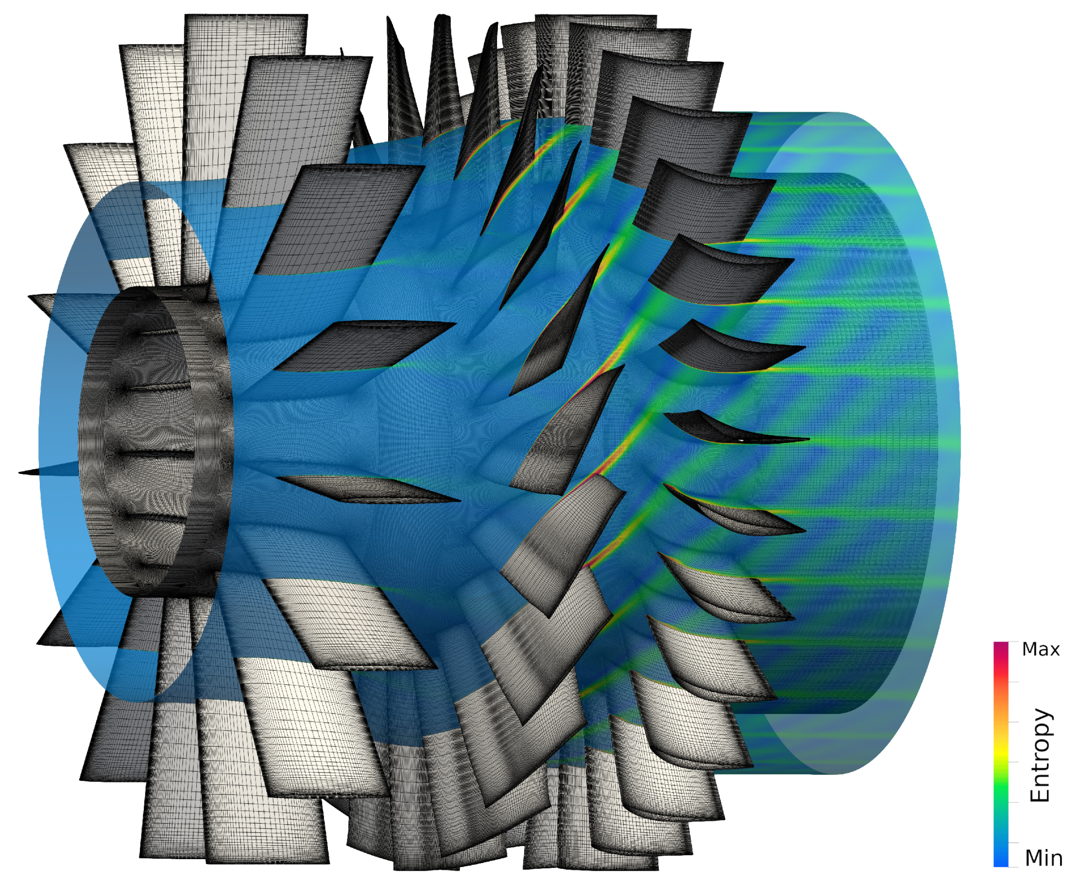
Starting from the same CAD models used for the FEM analyses, the CFD domain was easily defined and consisted of a full annulus, multi-row environment with IGV, rotor, and stator rows. An in-house mesh generator, suitable for both H-grids and O-grids, was used to build a viscous grid with wall refinement to better capture viscous effects in the boundary layer, ensuring values of y + 2 , adopted following the industrial practice for this kind of computation. In this case, an O-grid type was selected to obtain the overall multi-block grid shown in Figure 6. First, steady-state CFD simulations were performed to match the compressor operating point and evaluate mean flow quantities. This type of analysis requires only a single tangential sector for each blade row, taking advantage of the mixing plane approach to reduce computational cost. All the simulations used the k ω turbulence model in Wilcox’s formulation for the Navier–Stokes equation closure.
Inlet, outlet, walls, and periodicity boundary conditions for internal flows were imposed at the computational domain boundaries: at the inlet, span-wise distributions of total pressure, total temperature, blade-to-blade flow angle, and meridian flow angle were imposed, while at the outlet a span-wise distribution of static pressure was assigned. In steady analyses, the mixing plane approach was used to average the flow quantities passing from static to rotating blocks and vice versa, allowing the evaluation of the overall increase in static (and dynamic) pressure. Because of the averaging process, in this case, blades could not experience the wakes of upstream rows and other unsteady effects; thus, an unsteady multi-row analysis was performed to investigate stator–rotor interactions.
Unsteady multi-row analyses can be performed with both reduced-sector or full-annulus approaches, with the main aim to obtain a converged solution at each physical time step and an overall periodicity in time. For that case, the blade rows had a prime number of blades with respect to each other (15, 21, and 29), so a reduced-sector approach could not be adopted, and a full-annulus domain consisting of a 159-block domain was used (Figure 6). This allowed the evaluation of the unsteady pressure field experienced by the rotor, caused by the potential effect of downstream rows, together with the wakes generated by upstream rows. It must be noted that while other different mechanisms of unsteady excitation can occur, in this paper, only the interactions between IGV and stator with the rotor were considered. These unsteady phenomena resulted in a pressure field fluctuation experienced by the rotor blades through a periodic change in the blade loading. These perturbations were then processed by a DFT algorithm of the unsteady pressure field over the blade surface, extracting the pressure harmonics linked to the most relevant engine orders, and stored in terms of real and imaginary parts of the main pressure harmonics.

5.2. Unsteady Forcing Decomposition

As previously stated, the TRAF code already performs at runtime a first discrete Fourier decomposition in time of the unsteady pressure history on selected blades, given the desired engine orders (EOs), as follows:
P ( EO ) = 1 N d i v n t = 0 N d i v 1 p t e i ( EO ) 2 π N d i v n t
where EO is the engine order, p t is the discrete, equally spaced pressure signal in time, and N d i v 
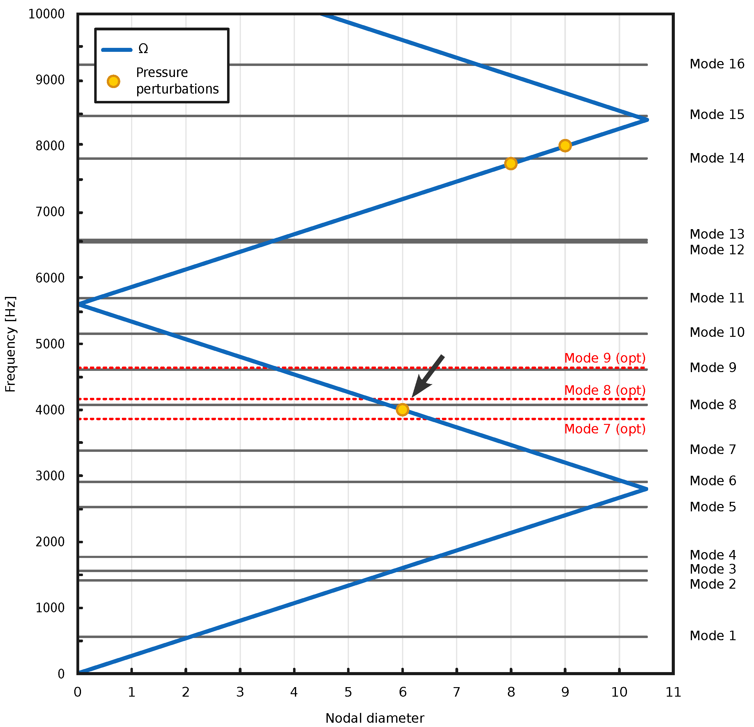
is the total number of samples that discretize a single rotor revolution. The unsteady forcing resulting at the end of each unsteady run was then further Fourier decomposed in space, in the circumferential direction, to obtain a single traveling wave exciting a corresponding mode shape in a cyclic environment, as predicted by the interference diagram (Figure 7). To do so, the Fourier coefficients in time on the blade surface were circumferentially decomposed on homologous points on adjacent blades (one on each blade, for a row pitch) by means of the in-house tool named OutDFT [33] with the following formula:
P ^ nd EO = 1 N k = 1 N P k ( EO ) e i ( nd ) 2 π N k
where nd is the circumferential order, P k ( EO ) is the discrete-time Fourier coefficient of the tangential distribution on corresponding surface points of the blade, and N is the blade count. The method also takes into account the aliasing phenomenon, as the resulting rotating forcing function is characterized by a nodal diameter ranging from N / 2 to + N / 2 , or from ( N 1 ) / 2 to + ( N 1 ) / 2 in the case of an odd blade count, as suggested by Nyquist’s theorem. The sign of nd defines the spinning direction: if positive, it defines a forward-rotating wave; if negative, a backward-rotating wave. The final outputs of the tool are complex pressure maps on the blade surface related to single rotating forcings. Such distributions account for the static (average pressure) and dynamic parts and can be directly loaded into the commercial FE software for the next topology optimization setup or used for a forced-response assessment inside the same environment.

6. Optimization Procedure

6.1. Optimization Algorithm

The topology optimization solution relies on gradient-based optimization techniques [34]. Several algorithms are available in OptiStruct: Method of Feasible Directions (MFD) [35], Sequential Quadratic Programming (SQP) [36], dual optimizer based on separable convex approximation (DUAL) [37] and large-scale optimization algorithm (BIGOPT). Delving into specifics, BIGOPT is a gradient-based method which offers a high computational efficiency with moderate memory requirements in comparison to MFD and SQP. The solver employs an iterative procedure, known as local approximation method, to determine the solution of the optimization problem. This process involves the following steps:
  • Analysis of the physical problem using finite elements;
  • Convergence test to determine whether or not the convergence is achieved;
  • Response screening to retain potentially active responses for the current iteration;
  • Design sensitivity analysis for retained responses;
  • Optimization of an explicit approximate problem based on the sensitivity information.
To ensure stable convergence, the solver restricts design variables changes within predefined move limits during each iteration, which confine the design updates to a narrow range within their specified bounds. These design updates are computed by solving an explicit approximate optimization problem based on the sensitivity information.
The algorithm is implemented as follows. A generic optimization problem, which involves minimizing f ( x ) based on a set of constraints, is described as:
min f ( x ) g i ( x ) = 0 , i = 1 , , m e g i ( x ) 0 , i = ( m e + 1 ) , , m x L x x U
where f ( x ) is the objective function, g i ( x ) is the ith constraint function, m e is the number of equality constraints, m is the total number of constraints, x is the design variable vector, and x L and x U are the lower- and upper-bound vectors of design variables, respectively.
If the BIGOPT algorithm is selected, OptiStruct converts this problem to an equivalent problem using the penalty method:
min Φ ( x ) = f ( x ) + r i = 1 m e q i g i ( x ) 2 + i = m e + 1 m q i max 0 , g i ( x ) 2 x L x x U
In OptiStruct, two convergence tests are employed. Regular convergence (design is feasible) is reached when convergence criteria are met for two consecutive iterations. This entails the change in the objective function is less than the objective tolerance over two consecutive iterations, and constraint violations are below 1%. At least three analyses are required for regular convergence, as the convergence is based on the comparison of true objective values (values obtained from an analysis at the latest design point). Soft convergence occurs when minimal or no change in design variables is observed for two consecutive iterations. Therefore, soft convergence requires one less iteration than regular convergence. Optimization runs based on a BIGOPT algorithm will be terminated if one of the following conditions is met:
Φ ϵ and the design is feasible .
2 Φ x k + 1 Φ x k Φ x k + 1 + Φ x k ϵ and the design is feasible .
The number of iteration steps exceeds N m a x
where Φ is the gradient of Φ ( x ) , k is the kth iteration step, ϵ is the convergence parameter, and N max is the allowed maximum iterations.

6.2. Interference Diagram and Crossing Selection

In order to perform a forced-response analysis, the results from a previous modal analysis are required. Indeed, the order of the pressure perturbation to consider was chosen so that it acted on the blade inducing a resonance condition, in our case, identifying the closest crossing of a natural frequency with the forcing on the ZZENF diagram, as shown in Figure 7. Pressure loads extracted from unsteady CFD simulation need to be imported and applied to the FE model, maintaining all constraint conditions of the modal analysis. The dynamic-pressure load field was transferred to the blade surface on the FEM mesh by rotating and translating CFD nodes, therefore computing the transformation matrix from the CFD to the solid domain with CloudCompare, an open-source tool.
In the depicted diagram (Figure 7), two distinct intersections emerge, providing viable points for the evaluation of the forced response and therefore for carrying out the optimization. These are, respectively, the intersection of the forcing of order 15 (nodal diameter 6) with frequency 8, and above, the one between the forcing of order 29 (at nodal diameter 8) and natural frequency 14. In this case, the first (indicated with an arrow) with a lower frequency was chosen. Lower frequencies are generally more critical; moreover, the forcing derives from the IGV and therefore, it is a wake effect, which results in a stronger flow perturbation than that due to potential effect deriving from the stator of order 29. For each element of the blade profile belonging to FE model, the magnitude and direction of the pressure were then linearly interpolated (Figure 3), given the wider spacing of CFD nodes compared to those in the solid mesh. The output of the analysis consisted of the displacement values for preselected nodes as a function of frequency, enabling the identification of resonance conditions and vibratory stress.

6.3. Forced-Response Results (Benchmark)

The primary objective of this analysis was to assess the rotor blade displacement induced by unsteady pressure harmonics. The forced response can be identified in the ZZENF diagram (or in Campbell’s diagram) as a resonance condition for the fluid and blade system. After the transfer of the unsteady pressure harmonic to the FEM model, a damping value was assigned, in terms of critical damping ratio, with reference to data from previous studies [38]. The total damping, which is the sum of mechanical and aerodynamic damping, was approximately taken equal to the aerodynamic damping alone, as it is more relevant, as expressed in Equation (15):
ξ = ξ m + ξ a ξ a = ζ ζ c = 0.001
where, for a damped harmonic oscillator, ξ is the damping ratio, ζ is the damping, and ζ c is the critical damping of a single degree of freedom. A forced-response analysis was then performed, with the selected order of perturbation, by employing both direct and modal methods to mutually validate each approach. The modal method was subsequently adopted as the primary outcome and was once again utilized for the final post-optimization steps, given its significantly more efficient calculation time. The displacements extracted as the output referred to the node with the maximum displacement amplitude on the blade’s external surface calculated with respect to mode shape 8 (Figure 8). Figure 9 illustrates the resulting displacement amplitude and phase versus frequency; it must be noted that the displacement in the z direction is much greater than the others. Additionally, the graph highlights two other natural frequencies (mode 7 at 3447 Hz and mode 9 at 4628 Hz), in which, however, the response remains relatively low. As previously observed, the forcing primarily excites the mode shape corresponding to the natural frequency in the middle. The higher response in the central natural frequency further validates the effective resonance condition of the forcing and the correct definition of the previous steps. The maximum values of displacement are summarized in Table 4, together with the resulting calculated total displacement.

6.4. Topology Optimization Settings

To initiate the optimization process, it is imperative to delineate both the design and non-design spaces. The former delineates areas where model elements can be removed from the original geometry, while the elements within the non-design space are kept unaltered and not considered by the solver. In this case, the blade region not to be modified was assigned to the non-design space. Additionally, a section of the blade base was also kept unchanged, considering that it formed the hub wall of the meridional channel and was therefore essential for guiding the flow inside the compressor. The rest of the blisk sector was included into the design space. The resulting classification is shown in Figure 10.
In the present work, the optimization constraints were imposed on the nodal displacement magnitude derived from the forced-response analysis, maximum stress value, and volume fraction. The first constraint was defined in the commercial FE software with the optimization response type “FRF displacement” (frequency response function displacement), referring to the same node with maximum displacement from the 8th natural frequency of the original geometry (which corresponded, approximately, to the forcing frequency). This constraint was set to the benchmark value calculated from the forced-response analysis, to ensure that the response of the blade to dynamic loads at that specific frequency did not increase despite the removal of material in the base of the blisk sector. The maximum value of the von Mises stress induced by a centrifugal load was also assigned as a design variable, even though this value did not pose a concern with the original geometry. This inclusion was made to ensure that stress levels did not surpass acceptable values. Notably, in this case, no significant impact of this parameter on the results was observed. Finally, the volume fraction v f was defined as the ratio of designable volume at current iteration v i d e s i g n and the initial designable volume v 0 d e s i g n (Equation (16)). This constraint was implemented to ensure the permanence of a minimum or maximum volume fraction in a specific part: in this case, it was assigned to the lower part of the blisk sector because of the tendency of the solver to delete the whole design space’s associated volume.
v f = v i d e s i g n v 0 d e s i g n
The most effective strategy for defining the optimization objective was identified as minimizing the total compliance. Compliance, being the strain energy of the structure, serves as a reciprocal measure of the structure’s stiffness. The compliance is defined for the entire component, as the objective functions need to be related to a global parameter. However, it can also be assigned to individual properties and materials. The objective of the minimum compliance problem is then to determine the optimal material density distribution that minimizes the structure deformation under the specific boundary and loading condition. Additionally, two other parameters were assigned to the design variable, not considered as strict constraints: the minimum member size control, set to 3 mm, and the cyclic feature repetition. The first one was used to achieve a solution with a clearly defined structure, avoiding thin or isolated pieces and checkerboarding. The second was set to obtain a solution which followed a repetitive circular pattern according to the starting angular sector, equal to 360 / 21 17 . 14 (resulting in a continuous solution at cut surfaces). The ultimate definition of imposed constraints and objectives is reported in Table 5.

7. Optimization Results

The output of the topology optimization of the compressor blisk is depicted in Figure 11. The red regions denote the solid state in the optimized configuration, whereas the blue areas represent the void state that can be eliminated to achieve the optimized geometry. Additionally, a threshold can be defined between these two states to guide the intermediate density elements towards either the void or solid state. The smoothness and regularity of the optimized geometry of the blisk computed by the solver is taken as a confirmation of the good convergence of the optimization process. However, to achieve an acceptable final design, the use of a CAD tool for geometry reconstruction would be recommended. The new component exhibits a mass reduction of approximately 32% compared to the original geometry (with a similar reduction in volume, given the homogeneity of the material). It is important to note that the mass reduction does not account for seals, which are necessary to reduce leakage losses during compressor operation, which should be reintroduced during CAD re-modeling. The irregular cavities resulting from the optimization on the rotor could also potentially lead to losses due to secondary air vortices and other phenomena. Therefore, it may be advisable to provide a closed hollow design with a flat surface to mitigate these effects. At this point, the geometry resulting from the optimization process (Figure 11 and Figure 12) was re-imported into the commercial FE software using a dedicated tool, for the definition of an FE model (Figure 13) which was employed for the final validation of the proposed methodology. The primary focus of this phase was to verify the actual forced-response displacement magnitude after the optimization, in conjunction with the updated stress resulting from the centrifugal load and natural frequencies of the new geometry. As depicted in Figure 13, the constraints remained consistent with those established previously, where still applicable.
Displacement and von Mises stress contours from the linear static analysis are shown in Figure 14. It is noteworthy that the values remained fundamentally similar in both cases; the peak value in the stress map where the constraints of the screw head were introduced was correctly addressed by the optimization, by preserving an area suitable for locking the component that allowed an effective distribution of the stress.
The comparison between the original and optimized geometry of the blisk was conducted under the same aerodynamic perturbation, determined by the same wake frequency (as indicated in the ZZENF diagram, Figure 7). By definition, as both the meridional channel of the compressor and the blade rows were kept unchanged, the aerodynamic forcing under consideration remained consistent throughout the optimization process of the rotor disk geometry. Under this hypothesis, the new geometry experienced a significant reduction in the forced-response displacement magnitude (Figure 15) compared to the original one for this forcing (Figure 9), due to both the shift in the natural frequencies of the system away from the forcing frequency (4000 Hz) and to an increase in the relative stiffness of the blade and disk system. In Figure 15, the peak of the forced response from the original geometry is indicated with a dotted line. Both of these aspects are evident from the frequency response graphs, which illustrate the shifting of peaks (i.e., natural frequencies of the model) away from the aerodynamic excitation frequency, as well as the decrease in the absolute displacement value, discernible from the scale of the graph. In Table 6, the comparison between original and optimized components in terms of volume and mass is summarized.

8. Conclusions

In the current study, a comprehensive design optimization procedure based on topological concepts for rotating components in turbomachinery was described. More specifically, the proposed topological optimization approach allowed a reduction in the mass of the rotor, taking into account the forced-response effect resulting from the unsteady aerodynamic interactions of the rotor blades with both upstream and downstream blade rows. A one-and-a-half-stage aeronautical axial compressor was selected as a test case to validate the procedure, which was based on two solvers: the TRAF code for the CFD analyses, and a commercial FE software for the FEM simulations. The newly optimized component showcased a mass reduction of around 32% compared to the original geometry. In terms of dynamic performance, the displacement values resulting from the forced response exhibited a substantial reduction in magnitude, under the same pressure perturbation. The presented results confirmed the effectiveness of the proposed methodology, suggesting its potential applicability in both experimental and industrial settings.

9. Future Developments

Potential future developments for this work could include additional considerations. For instance, the forced-response assessment could be expanded by utilizing a different set of points than those explored in this paper. Furthermore, the definition of the objective function in the optimization process could involve alternative formulations that simultaneously incorporate cases of static and frequency analyses. In a more comprehensive approach, various perturbations from different engine orders might also be incorporated. Finally, an interesting possibility lies in the use of the topological lattice optimization (Figure 16). Lattice structure optimization is a method employed in the generation of components that integrate both solid and lattice structures, which are characterized by an extremely high stiffness-to-density ratio. The resulting component is a structure blended with solid parts and lattice zones of varying material volume. With an approach similar to the one used for topological optimization, this technology was particularly developed to support design innovation through additive layer manufacturing.

Author Contributions

All the authors decided on the methodology, test case, and contributed to the final review. A.B. formulated the method, performed the numerical simulations, and wrote the result section of the manuscript. A.C. wrote the part related to the FEM framework. L.P. wrote the CFD framework section of the manuscript. M.M. and E.M. supervised the work. All authors have read and agreed to the published version of the manuscript.

Funding

This research received no external funding.

Data Availability Statement

The original contributions presented in the study are included in the article, further inquiries can be directed to the corresponding author.

Conflicts of Interest

The authors declare no conflicts of interest.

Abbreviations

The following abbreviations are used in this manuscript:
AMAdditive manufacturing
BIGOPTLarge-scale optimization algorithm
CADComputer aided design
CFDComputational Fluid Dynamics
CNCComputer Numerically Controlled
DFTDiscrete Fourier transform
EDMElectrical Discharge Machining
EOEngine order
FEMFinite Element Method
IGVInlet guide vane
TOTopology optimization
ZZENFZig-zag-shaped excitation line in the nodal diameter versus Frequency

References

  1. Lei, X.; Qi, M.; Sun, H.; Hu, L. Investigation on the Shock Control Using Grooved Surface in a Linear Turbine Nozzle. J. Turbomach. 2017, 139, 121008. [Google Scholar] [CrossRef]
  2. Novotny, V.; Spale, J.; Stunova, B.B.; Kolovratnik, M.; Vitvarova, M.; Zikmund, P. 3D Printing in Turbomachinery: Overview of Technologies, Applications and Possibilities for Industry 4.0. In Proceedings of the ASME Turbo Expo 2019, Phoenix, AZ, USA, 17–21 June 2019; p. V006T24A021. [Google Scholar] [CrossRef]
  3. Blakey-Milner, B.; Gradl, P.; Snedden, G.; Brooks, M.; Pitot, J.; Lopez, E.; Leary, M.; Berto, F.; du Plessis, A. Metal additive manufacturing in aerospace: A review. Mater. Des. 2021, 209, 110008. [Google Scholar] [CrossRef]
  4. González-Barrio, H.; Calleja-Ochoa, A.; Lamikiz, A.; López de Lacalle, L.N. Manufacturing Processes of Integral Blade Rotors for Turbomachinery, Processes and New Approaches. Appl. Sci. 2020, 10, 3063. [Google Scholar] [CrossRef]
  5. Meli, E.; Rindi, A.; Ridolfi, A.; Furferi, R.; Buonamici, F.; Iurisci, G.; Corbo, S.; Cangioli, F. Design and Production of Innovative Turbomachinery Components via Topology Optimization and Additive Manufacturing. Int. J. Rotating Mach. 2019, 2019, 9546831. [Google Scholar] [CrossRef]
  6. Chen, K.H. Investigation of tool orientation for milling blade of impeller in five-axis machining. Int. J. Adv. Manuf. Technol. 2011, 52, 235–244. [Google Scholar] [CrossRef]
  7. Bhavikatti, S.; Ramakrishnan, C. Optimum shape design of rotating disks. Comput. Struct. 1980, 11, 397–401. [Google Scholar] [CrossRef]
  8. Zhang, M.; Gou, W.; Li, L.; Wang, X.; Yue, Z. Multidisciplinary design and optimization of the twin-web turbine disk. Struct. Multidiscip. Optim. 2016, 53, 1129–1141. [Google Scholar] [CrossRef]
  9. Kazemi, H.; Vaziri, A.; Norato, J.A. Topology Optimization of Structures Made of Discrete Geometric Components With Different Materials. J. Mech. Des. 2018, 140, 111401. [Google Scholar] [CrossRef]
  10. Shi, G.; Guan, C.; Quan, D.; Wu, D.; Tang, L.; Gao, T. An aerospace bracket designed by thermo-elastic topology optimization and manufactured by additive manufacturing. Chin. J. Aeronaut. 2020, 33, 1252–1259. [Google Scholar] [CrossRef]
  11. Sosnovik, I.; Oseledets, I. Neural networks for topology optimization. Russ. J. Numer. Anal. Math. Model. 2019, 34, 215–223. [Google Scholar] [CrossRef]
  12. Minin, I.; Matveev, S.; Fedorov, M.; Zacharov, I.; Rykovanov, S. Benchmarks of Cuda-Based GMRES Solver for Toeplitz and Hankel Matrices and Applications to Topology Optimization of Photonic Components. Comput. Math. Model. 2021, 32, 438–452. [Google Scholar] [CrossRef]
  13. Wang, Y.; Xu, S.; Zhou, Y.; Zhou, C.; Wan, S.; Yang, J.; Wang, B. Intercoupling aeroelastic stability topology optimization for the design of bend-twisted hollow blade in a turbomachinery cascade. Struct. Multidiscip. Optim. 2023, 66, 212. [Google Scholar] [CrossRef]
  14. Yan, C.; Liu, C.; Du, H.; Wang, C.; Yin, Z. Topology optimization of turbine disk considering maximum stress prediction and constraints. Chin. J. Aeronaut. 2023, 36, 182–206. [Google Scholar] [CrossRef]
  15. Ulu, E.; Huang, R.; Kara, L.B.; Whitefoot, K.S. Concurrent Structure and Process Optimization for Minimum Cost Metal Additive Manufacturing. J. Mech. Des. 2019, 141, 061701. [Google Scholar] [CrossRef]
  16. Fayaz, G.; Kazemzadeh, S. Towards additive manufacturing of compressor impellers: 3D modeling of multilayer laser solid freeform fabrication of nickel alloy 625 powder mixed with nano-CeO2 on AISI 4140. Addit. Manuf. 2018, 20, 182–188. [Google Scholar] [CrossRef]
  17. Zhu, J.; Zhou, H.; Wang, C.; Zhou, L.; Yuan, S.; Zhang, W. A review of topology optimization for additive manufacturing: Status and challenges. Chin. J. Aeronaut. 2021, 34, 91–110. [Google Scholar] [CrossRef]
  18. Liu, S.; Mi, D.; Wen, C.; Zheng, Y. Topology Optimization Design With Addictive Manufacturing Constraints for Centrifugal Impeller. J. Phys. Conf. Ser. 2022, 2252, 012026. [Google Scholar] [CrossRef]
  19. Pinelli, L.; Amedei, A.; Meli, E.; Vanti, F.; Romani, B.; Benvenuti, G.; Fabbrini, M.; Morganti, N.; Rindi, A.; Arnone, A. Innovative Design, Structural Optimization, and Additive Manufacturing of New-Generation Turbine Blades. J. Turbomach. 2021, 144, 011006. [Google Scholar] [CrossRef]
  20. Magerramova, L.; Vasilyev, B.; Kinzburskiy, V. Novel Designs of Turbine Blades for Additive Manufacturing. In Proceedings of the ASME Turbo Expo 2016, Seoul, Republic of Korea, 13–17 June 2016; p. V05CT18A001. [Google Scholar] [CrossRef]
  21. Ebrahim, A.A.A.; Ameddah, H.; Outtas, T.; Almutawakel, A. Design of graded lattice structures in turbine blades using topology optimization. Int. J. Comput. Integr. Manuf. 2021, 34, 370–384. [Google Scholar] [CrossRef]
  22. Zhang, M.; Liu, Y.; Yang, J.; Wang, Y. Aerodynamic topology optimization on tip configurations of turbine blades. J. Mech. Sci. Technol. 2021, 35, 2861–2870. [Google Scholar] [CrossRef]
  23. Ghosh, S.; Fernandez, E.; Kapat, J. Fluid-Thermal Topology Optimization of Gas Turbine Blade Internal Cooling Ducts. J. Mech. Des. 2021, 144, 051703. [Google Scholar] [CrossRef]
  24. Ostanin, I. “String art” approach to the design and manufacturing of optimal composite materials and structures. Compos. Struct. 2020, 246, 112396. [Google Scholar] [CrossRef]
  25. Poli, F.; Marconcini, M.; Pacciani, R.; Magarielli, D.; Spano, E.; Arnone, A. Exploiting GPU-Based HPC Architectures to Accelerate an Unsteady CFD Solver for Turbomachinery Applications. In Proceedings of the ASME Turbo Expo 2022, Rotterdam, The Netherlands, 13–17 June 2022; p. V10CT32A035. [Google Scholar] [CrossRef]
  26. Li, L.; Xu, W.; Tan, Y.; Yang, Y.; Yang, J.; Tan, D. Fluid-induced vibration evolution mechanism of multiphase free sink vortex and the multi-source vibration sensing method. Mech. Syst. Signal Process. 2023, 189, 110058. [Google Scholar] [CrossRef]
  27. Li, L.; Li, Q.; Ni, Y.; Wang, C.; Tan, Y.; Tan, D. Critical penetrating vibration evolution behaviors of the gas-liquid coupled vortex flow. Energy 2024, 292, 130236. [Google Scholar] [CrossRef]
  28. Wang, B.; Wang, G.; Tian, K.; Shi, Y.; Zhou, C.; Liu, H.; Xu, S. A preliminary design method for axisymmetric turbomachinery disks based on topology optimization. Proc. Inst. Mech. Eng. Part C J. Mech. Eng. Sci. 2021, 236, 3313–3322. [Google Scholar] [CrossRef]
  29. Wang, B.; Wang, G.; Shi, Y.; Huang, L.; Tian, K. Stress-constrained thermo-elastic topology optimization of axisymmetric disks considering temperature-dependent material properties. Mech. Adv. Mater. Struct. 2021, 29, 7459–7475. [Google Scholar] [CrossRef]
  30. Ngim, D.; Liu, J.S.; Soar, R. Design optimization for manufacturability of axisymmetric continuum structures using metamorphic development. Int. J. Solids Struct. 2007, 44, 685–704. [Google Scholar] [CrossRef]
  31. Gisario, A.; Kazarian, M.; Martina, F.; Mehrpouya, M. Metal additive manufacturing in the commercial aviation industry: A review. J. Manuf. Syst. 2019, 53, 124–149. [Google Scholar] [CrossRef]
  32. Pacciani, R.; Marconcini, M.; Arnone, A. Comparison of the AUSM+-up and other advection schemes for turbomachinery applications. Shock Waves 2019, 29, 705–716. [Google Scholar] [CrossRef]
  33. Pinelli, L.; Lori, F.; Marconcini, M.; Pacciani, R.; Arnone, A. Validation of a Modal Work Approach for Forced Response Analysis of Bladed Disks. Appl. Sci. 2021, 11, 5437. [Google Scholar] [CrossRef]
  34. Jameson, A. Gradient Based Optimization Methods; MAE Technical Report No. 2057; Princeton University: Princeton, NJ, USA, 1995. [Google Scholar]
  35. Chen, X.; Kostreva, M.M. Methods of Feasible Directions: A Review. In Progress in Optimization: Contributions from Australasia; Yang, X., Mees, A.I., Fisher, M., Jennings, L., Eds.; Springer: Boston, MA, USA, 2000; pp. 205–219. [Google Scholar] [CrossRef]
  36. Boggs, P.T.; Tolle, J.W. Sequential Quadratic Programming. Acta Numer. 1995, 4, 1–51. [Google Scholar] [CrossRef]
  37. Fleury, C. Dual Methods for Convex Separable Problems. In Optimization of Large Structural Systems; Rozvany, G.I.N., Ed.; Springer: Dordrecht, The Netherlands, 1993; pp. 509–530. [Google Scholar] [CrossRef]
  38. Vanti, F.; Pinelli, L.; Poli, F.; Arnone, A. Aeroelastic investigation of turbine blade assemblies: Cluster system and mistuned rows. In Proceedings of the 12th European Conference on Turbomachinery Fluid Dynamics & Thermodynamics, Stockholm, Sweden, 3–7 April 2017. [Google Scholar] [CrossRef]
Figure 1. Overall workflow chart showing FEM and CFD interaction.
Energies 17 01883 g001
Figure 2. CAD model of the 1 ½ stage aeronautical compressor. Rotor blisk highlighted in red.
Energies 17 01883 g002
Figure 3. Definition of FEM sector, constraints, and surface loading.
Energies 17 01883 g003
Figure 4. Displacement and von Mises stress map from the linear static analysis.
Energies 17 01883 g004
Figure 5. First three mode shapes resulting from the modal analysis.
Energies 17 01883 g005
Figure 6. CFD grid of the whole annulus for unsteady simulation with a flow field described by entropy contours.
Energies 17 01883 g006
Figure 7. ZZENF diagram showing the nodal diameter and frequency of the extracted pressure perturbations and blade natural frequencies. In dashed red lines are the natural frequencies of the optimized geometry close to forcing excitation. The arrow indicates the selected aerodynamic forcing.
Energies 17 01883 g007
Figure 8. Eighth mode shape, the arrow pinpoints the node with maximum displacement.
Energies 17 01883 g008
Figure 9. Displacement amplitude and phase vs. frequency of the selected node, from the forced-response analysis with the original blisk geometry.
Energies 17 01883 g009
Figure 10. Definition of design (white) and non-design space (red) for the topology optimization.
Energies 17 01883 g010
Figure 11. Optimization results for the blisk sector.
Energies 17 01883 g011
Figure 12. Optimized geometry (a) and render (b) of the entire rotor blisk.
Energies 17 01883 g012
Figure 13. FE model with optimized geometry.
Energies 17 01883 g013
Figure 14. Displacement and von Mises stress map for optimized geometry.
Energies 17 01883 g014
Figure 15. Displacement amplitude and phase vs. frequency of the selected node, from the forced response analysis with optimized blisk geometry. Vertical dotted line reports the Campbell crossing of the original rotor blisk.
Energies 17 01883 g015
Figure 16. Example of lattice optimization applied to the same case.
Energies 17 01883 g016
Table 1. Mechanical properties of the titanium alloy Ti-6Al-4V.
Titanium Ti-6Al-4V
Young’s modulus116,500 [MPa]
Poisson ratio3.225 × 10−1 [-]
Density4.43 × 103 [kg/m3]
Ultimate tensile strength900 [MPa]
Stress amplitude (1010 cycles)450 [MPa]
Table 2. Description of FEM constraints.
FEM ConstraintsConstrained Direction
aAxial, radial, tangential
bAxial
cTangential
dAxial
eAxial, radial, tangential
fAxial
gAxial
hApplied dynamic pressure load
Table 3. First ten calculated natural frequencies of the rotor blisk.
Mode NumberFrequency [Hz]
Mode 1557.79
Mode 21415.20
Mode 31560.74
Mode 41772.81
Mode 52529.63
Mode 62910.06
Mode 73377.36
Mode 84073.29
Mode 94611.52
Mode 105150.58
Table 4. Resulting forced-response displacement values.
Displacement x [mm]0.0015
Displacement y [mm]0.0386
Displacement z [mm]0.0594
Resulting total displacement [mm]0.0708
Table 5. Applied constraints and objectives.
Constraints
Volume fraction (design) v f 0.5
FRF displacement u 0.07 mm
Stress value σ 450 MPa
Objective
Total complianceminimize
Table 6. Mass and volume comparison between original and optimized components.
Volume [mm3]Mass [kg]
Original sector43,055.730.1907
Optimized sector29,267.360.1297
Reduction32%
Disclaimer/Publisher’s Note: The statements, opinions and data contained in all publications are solely those of the individual author(s) and contributor(s) and not of MDPI and/or the editor(s). MDPI and/or the editor(s) disclaim responsibility for any injury to people or property resulting from any ideas, methods, instructions or products referred to in the content.

