Article

Approach to Design of Piezoelectric Energy Harvester for Sensors on Electric Machine Rotors

Department of Automotive Mechatronics, Institute of Automotive Engineering (IFS), Faculty 7: Engineering Design, Production Engineering and Automotive Engineering (F07), University of Stuttgart, 70569 Stuttgart, Germany
*
Author to whom correspondence should be addressed.
Energies 2024, 17(8), 1884; https://doi.org/10.3390/en17081884
Submission received: 1 March 2024 / Revised: 26 March 2024 / Accepted: 4 April 2024 / Published: 15 April 2024
(This article belongs to the Special Issue Energy Harvesting and Storage for Microsystems)

Abstract

:
The reliability and efficiency of components are key aspects in the automotive industry. Electric machines become the focus of development. Thus, improvements in efficiency and reliability have gained significance. While it is established to attach sensors to the fixed parts of machines, such as stators, moving parts like rotors pose a major challenge due to the power supply. Piezoelectric generators can operate as energy harvesters on rotors and thus enable the rotor-based integration of sensors. The research in this article proposes the first approach to the design of a piezoelectric energy harvester (PEH) for an electric machine rotor dedicated to powering a wireless sensor system. After introducing the field of PEHs, the integration of the proposed device on a rotor shaft is presented. Further, a gap between the provided and needed data for the design of a PEH is identified. To overcome this gap, a method is presented, starting with the definition of the rotor shaft dimensions and the applied mechanical loads, including a method for the calculation of the imbalance of the rotor. With the first set of dimensions of the shaft and PEH, a co-simulation is performed to calculate the power output of this rotor and PEH set. The results of the simulation indicate the feasible implementation of the PEH on the rotor, providing enough energy to power a temperature sensor.

1. Introduction

Increasing the efficiency of technical applications is currently a growing topic of interest as the energy demands of society increase [1]. In this context, one possible solution is energy harvesting, which allows for the creation of self-powered systems like wireless sensor systems, which enable new functions that contribute to improvements in the efficiency of technical applications. With the introduction of electric machines (EMs) into the automotive industry, their requirements must be adapted to the high standards of the automotive industry. The key aspects in this domain are reliability and efficiency. Numerous studies have investigated methods to improve both aspects. These studies are based on sensor data, which measure the physical properties of EMs.
Regarding reliability and the associated failure safety, sensor data are used for condition monitoring. Deviations from the normal state can be detected by monitoring the actual state of the EM, and, with this, critical damage to the machine caused by faults can be prevented. Vaimann et al. [2] and Meng et al. [3] indicated that the monitoring of the temperature inside a radial permanent magnet machine is a significant aspect in preventing failure. Regarding the magnets of such an EM, measuring the magnets’ temperature prevents demagnetization and hence a loss of performance up to total failure. The field of predictive maintenance, as presented by Antonio-Daviu [4] and Lu et al. [5], shows the necessity for comprehensive sensor data as input for the relevant methods. The additional measuring of the magnetic flux of the EM and the mechanical behavior extends the need for sensors on the rotor. To implement a machine learning-based fault detection method for an electric vehicle powertrain, Dettinger et al. [6] investigated the use of a digital twin, including an EM. Consequently, sensors have been used as input for fault detection.
Considering efficiency, sensor data lead to a better understanding of the physical behavior and properties of EMs. For example, Baumann et al. [7] identified the difference between the measurement and simulation of the rotor temperature and showed that measuring the temperature could support the extension of the temperature limit by 10% compared with the implemented calculation, leading to an increase in the operating range for the EM.
While measuring the physical variables of the stator is common practice, there are unique challenges for sensors on the rotor. The main challenges are as follows:
  • Power supply;
  • Data transmission.
As the system discussed here is a rotating system, it is essential to minimize its mass. For the power supply, the literature presents several solutions, which can be divided into the following supply categories:
  • Energy storage (batteries and capacitors) [8];
  • Direct power supplies [9];
  • Wireless power supplies [10,11];
  • Energy harvesting [12].
Table 1 gives an overview of the possible sensors, their power consumption, and, according to this, the necessary range of the power output of the chosen supply system.
Regarding rotating systems, energy harvesting (EH) offers advantages compared with the other supply categories. No recharging of the energy storage is needed, and regular maintenance to prevent the failure of direct power transmission devices, like slip rings, due to mechanical wear is not necessary [16]. The most common solution for a wireless power supply is transmission via electromagnetic induction with coils. In EMs, negative interactions with their electromagnetic field are very likely. Here, EH, especially via a piezoelectric energy harvester (PEH), which Erturk [17] characterized as an EH device with a high power density compared with other EH applications, circumvents the problem of the negative interaction with the EM. PEHs use the mechanical stress of the rotor shaft, which is a natural byproduct during the operation of EMs.
The purpose of this article is to provide an approach to the application of a PEH on the rotor shaft of an EM. After an introduction to the field of PEHs and the presentation of the investigated PEH system, the essential problems occurring in the design of a PEH are discussed. Enabling the development of a PEH while the EM is still in the early stages of the design process is the target of this approach. Therefore, the gap between the provided and required data for PEH design, as well as a method to close this gap, is discussed. The method includes various simulation models to calculate the needed data as input for the PEH and the PEH system itself. Each model, including a description of the fundamental approaches adopted to deduce the models, is briefly discussed. The design considers the energy provided by the PEH and the operating strategies of the sensor system powered by the PEH. Moreover, feedback on the design of the rotor shaft is given for the optimal operation of the whole system. After the presentation of the method, results from an exemplary implementation case are discussed.

2. Piezoelectric Energy Harvester

PEHs use piezoelectric materials (PM), which convert mechanical stress into an electric charge. By accelerating a seismic mass placed on the PM, the motion of the structure, like vibration, is converted. Therefore, a cantilever beam with one or two PM layers is added to the system, converting the motion into mechanical stress in the beam. This is the most common method of harvesting motion, as reviewed by Daukaev et al. [18]. Micek et al. [19] gave an example of the direct inducement of mechanical stress in the PM through the structure at which the PM is placed. They investigated a PM placed on a rotor shaft, inducing mechanical loads via a belt transmission, driving the shaft.
Regardless of the way that the mechanical stress is induced in the PM, it must be an alternating stress to generate a constant electric charge, resulting in an AC voltage generated by a PM. For rotating PEHs, the mechanical stress must alternate in the rotating system. 
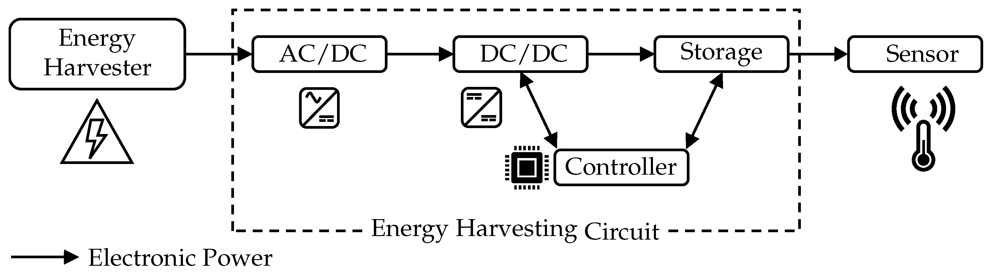
Figure 1 shows a general schematic illustration of an energy harvesting system. In the context of EH to power sensors, the harvester is called a micro-power generator. The system is divided into three parts:
  • Energy harvester;
  • Energy harvesting circuit;
  • Sensor/load.
In the case of PEHs, the micro-power generator is the PM, and for applications where the PM is placed on an uneven surface, a macro-fiber composite (MFC) was developed by the National Aeronautics and Space Administration (NASA) in 1996. They combined piezoceramic fibers with resin into a patch. Therefore, the patch is more flexible compared to pure piezoceramics and thus ideal for rotor-sided placement, and it is used as the PM in the presented method. Further, the dimensions of the MFC are set by the standard information given in the data sheet [21]. All patches have a rectangular shape. After producing the electric charge and thus an electric voltage in the PM, the energy harvesting circuit (EHC) transforms the voltage. For most common applications in the field of EH, the provided AC voltage has to be converted into a DC voltage and further regulated in the applicable voltage range. Due to the fact that the output of the PM is not constant, electrical storage is necessary, buffering the produced power, thus stabilizing the output voltage for the load, which, in this application, is a sensor. In addition, the EHC contains a micro-controller responsible for controlling the charging of the storage and activation of the sensor. An example of an EHC was presented by Dembowski [22].
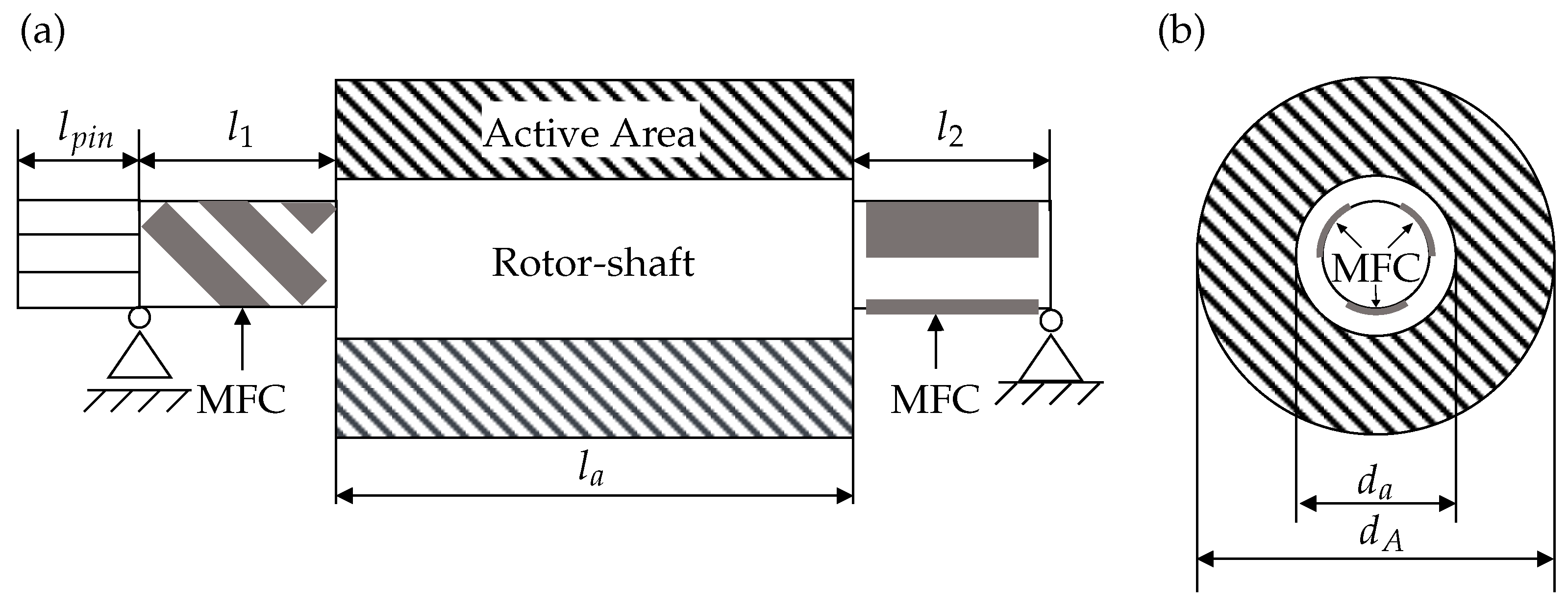
In the method presented in this article, the PEH uses the direct inducement of mechanical stress in the PM; hence, the PM is mounted directly on the rotor shaft. In this way, it can be assumed that the mechanical stresses in the PM and on the surface of the shaft are equivalent. 
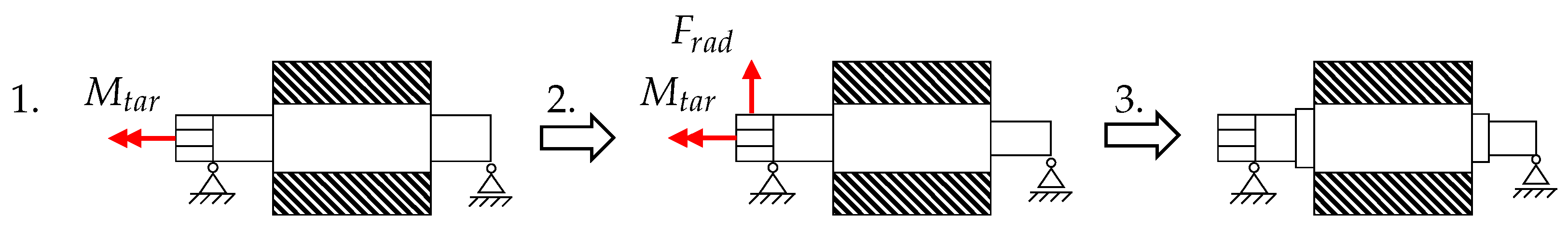
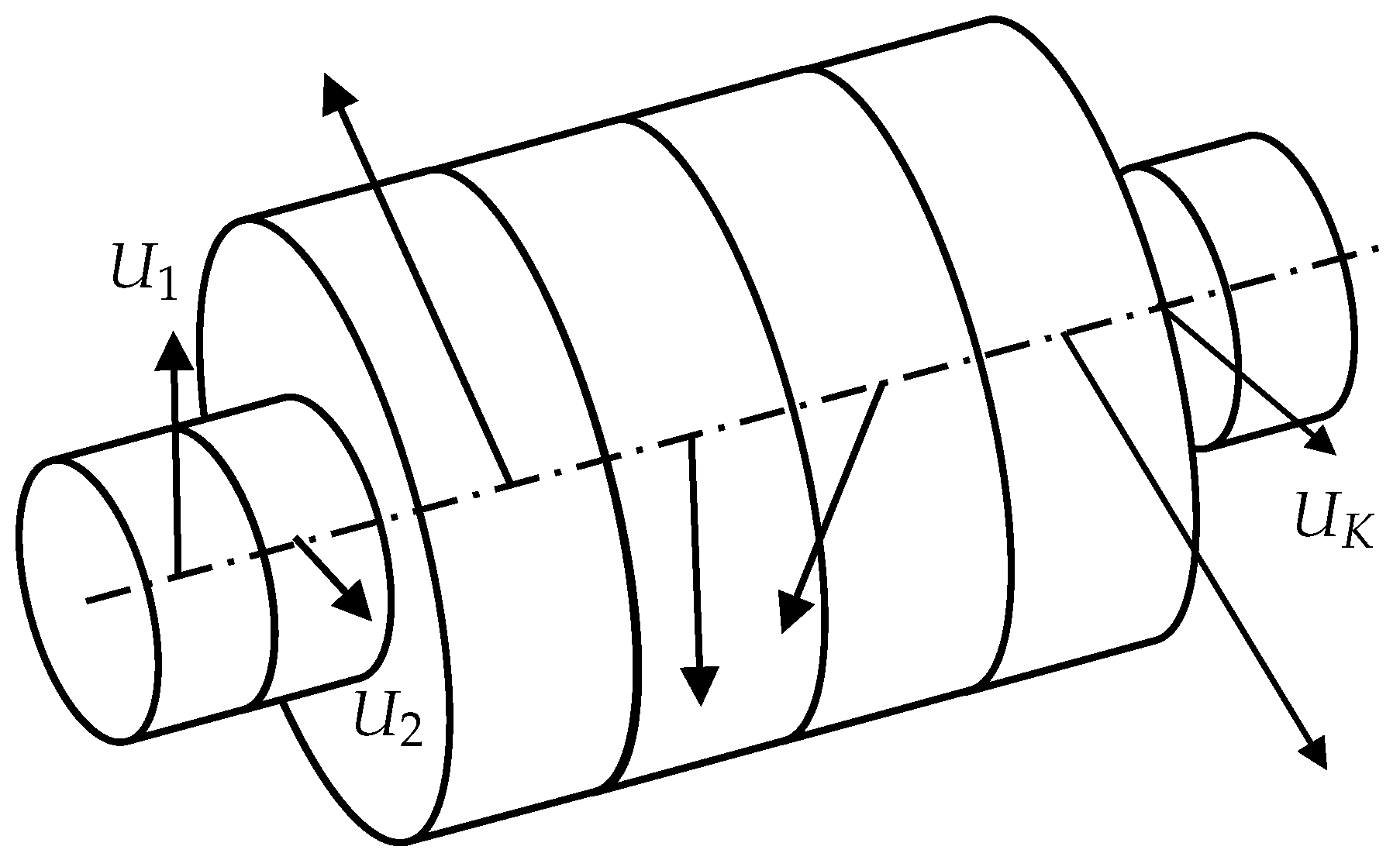
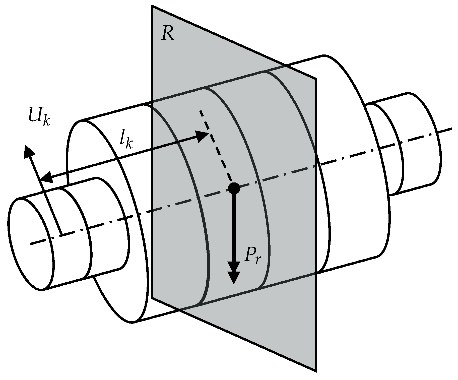
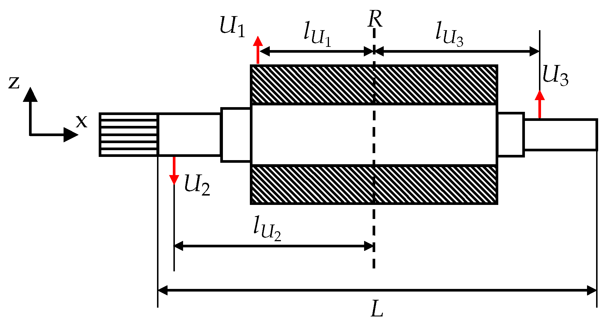
Figure 2 shows a schematic of a rotor including MFC patches as a PM. The length as well as the diameters of each part of the shaft can be calculated through the method presented in the following. The patches are placed outside the active area of the rotor and the mechanical stresses in this area are torsional and bending stresses, which both result from the torque generated in the EM. The bending stress occurs due to the radial force created by the pinion when transmitting the generated torque. In addition, the imbalance of the shaft induces bending stress. The MFC patches for the bending stress are placed with their piezoceramic fibers along the longitudinal axis of the shaft, where, for the torsional stress, they are rotated by an angle of  45 . On each side, three patches are placed, with those for the bending stresses separated by an angle of  120 , as shown in Figure 2b.

Challenges in Designing PEH for Rotor Shafts

The design of PEHs requires knowledge about the mechanical stress applied, which is, in this case, mechanical stress on the surface of the rotor shaft. This means that the design of the EM, i.e., the design of the rotor shaft, is mandatory before starting the design process of the PEH. 
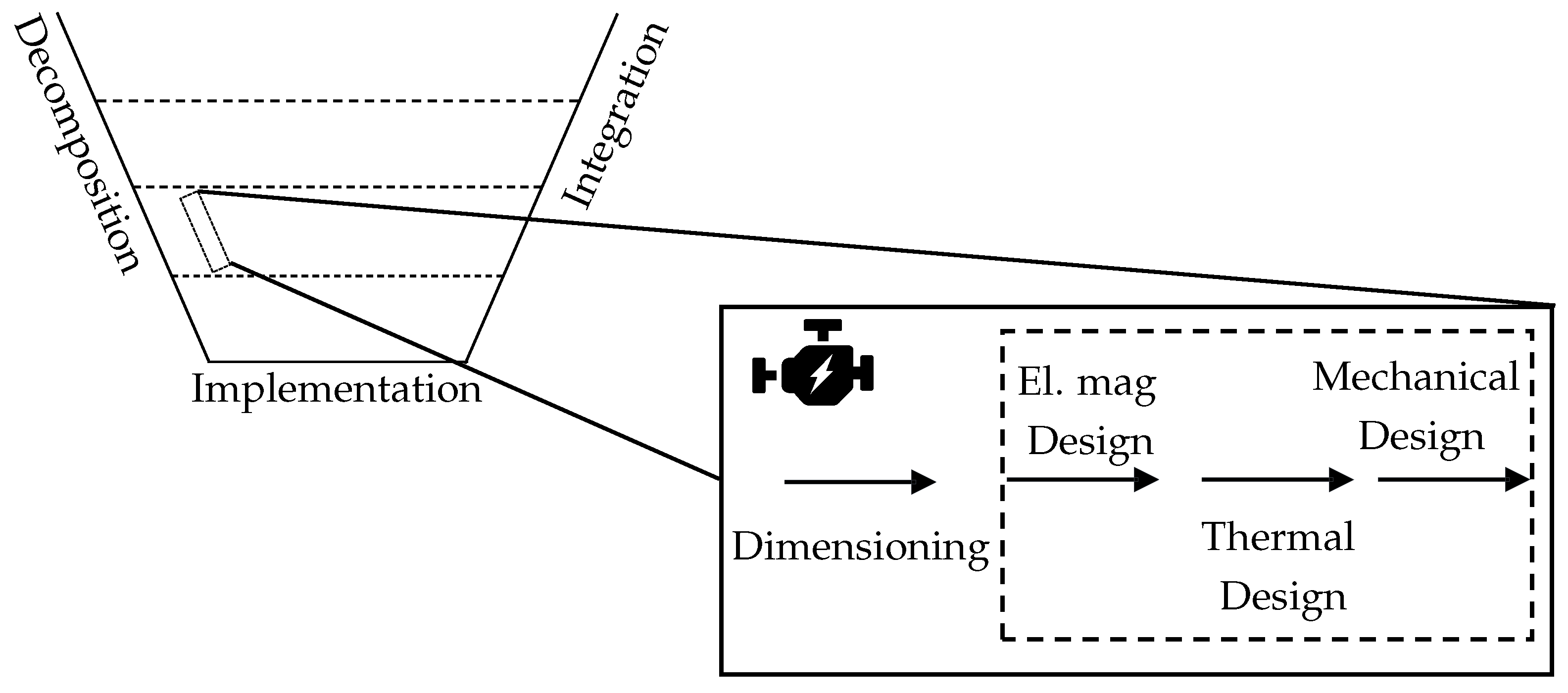
Figure 3 shows the V-model for the development of mechatronic systems defined by [23], using the PEH as an exemplary component of the overall vehicle development. The V-model is used to determine the possible starting point of the PEH design. With the start at the upper left, a pursued business model is defined, based on the system to be developed. The highest system level is represented by the entire vehicle, comprising various aspects, including the requirement specifications. From this, functions are derived, realizing the requirements. The system is decomposed and subdivided into lower subsystems needed to fulfill the functions defined above. In the given example, this is the EM with exemplary requirements for the power output or durability due to functions like condition monitoring and predictive maintenance. The subsystems are decomposed further, down to the component level, in the last step. Here, the rotor shaft, power electronics, or sensors, including PEHs, are categorized. In each step, the requirements for the following subsystem and their corresponding functions are derived. Proceeding through the V-model, the level of detail increases corresponding to the decomposition. Data generated at each step in the development process are available for the following subsystems. According to the work of Daukaev et al. [18] and Lei et al. [24], and as illustrated in Figure 3, the design process of the EM starts with electromagnetic design and ends with mechanical design. The development of the components follows the order of the provided data, as illustrated in Figure 3. Therefore, the sizing of the rotor shaft is one of the last aspects to be determined. Due to this, knowledge about the mechanical stress on the surface of the shaft is only provided in the final design stage of EMs. Calculations or simulations regarding the power output of a PEH system and thus the realization of a sensor system can therefore only be achieved at the end of EM development. Possible adaptions to the shaft of the EM, increasing the power output to the required level, are therefore ruled out or are associated with high costs.
This results in the need for the development of PEHs parallel to EMs, especially in the context of PEHs powering sensor systems integrated with the operation of the EM, providing the potential for the increased reliability and efficiency of EMs, as presented by Meng et al. [3] and Baumann et al. [7]. For parallel design, PEHs must move one subsystem level further in the V-model. Further, PEH design before the process of mechanical design is necessary, so that the PEH defines the requirements for the rotor shaft. As the degree of detail decreases when moving up through the V-model, the provided data for the PEH design decrease as well. Provided data are now a requirement for the system vehicle. To enable parallel development, a method is necessary that adapts the PEH design from the component level to the new system level, where development takes place.
This method is presented in the following sections. It also defines the minimum amount of required data for the design process of EMs and thus the possible starting point for pre-PEH development.

3. Method for Design of PEHs on Rotor Shafts of Traction Machines

In the following section, a method is presented for the design of a PEH on the rotor shaft of an EM, especially those used as traction machines in vehicles. The aim of the method is to be able to give an initial estimation for the power output of such a PEH. Further, it delivers the first design of the rotor shaft, including the required dimensions for the implementation of PEHs powering a wireless sensor system. Figure 4 shows an overview of the method. It is divided into three main parts, starting with the initial design of the rotor shaft based on the given requirements from the vehicle and calculating the mechanical stress on the surface of the shaft as input for the PEH design. The second part of the method deals with the simulation of the PEH system, including the PM, power electronics, and sensor system with wireless data transmission. With a given operating strategy for the sensor and driving scenarios for the vehicle, the PEH is validated in the third step. The validation is used as feedback on the first and second parts to optimize the whole system. If the validation is successful, the method ends and the generated data are transmitted to the component design stage.

3.1. First Draft of the Shaft

For the design of PEHs, the mechanical stress occurring in the operation of the EM on the surface of the rotor shaft has to be determined. Additionally, the required data for the design of EMs must be examined, as well as the data from the overall vehicle design provided in this stage of design. They represent the inputs for the PEH design method. For this, a closer inspection of the EM design process must be performed first, starting with the electromagnetic design. A common tool to calculate the first dimensions of EMs is the torque per rotor volume (TRV) [25]. The TRV defines the active area of the EM and thus the active length  l a  and active outer and inner diameters  d A  and  d a , as illustrated in Figure 2. The input in the TRV is the target torque  M t a r  of the EM in combination with the maximum rotating speed  n m a x .
Figure 4. Method overview for design of PEHs on shafts.
Energies 17 01884 g004
Table 2 shows the provided data in this stage of the overall design process. With this, a first draft of the shaft is possible considering the loads due to the targeted torque. For the rotor shaft, the following assumptions are made:
  • One driven end via pinion;
  • Double bearing;
  • Solid shaft;
  • All loads in zx plane;
  • Calculations based on DIN 743 [26].
Figure 5 shows the iterations for the first draft of a shaft, including the loads.  F r a d  is the radial force resulting from transmitting the created torque through the pinion at the end of the shaft. As  F r a d  depends on the diameter of the pinion, in the first step, the diameter d for the whole shaft is calculated,
d = 16 × M t a r π × τ t W 3 ,
based on  M t a r  and the material constant  τ t W . The lengths of the shaft are first set according to the equations
l 1 = l 2 = 0.5 × l a
l p i n = 0.25 × l a ,
where  l 1  is the length on the left side of the active area,  l 2  is the length on the right side and  l p i n  is the length of the pinion, which can be seen in Figure 2. Thus, the bending moment behavior  M b ( x )  is calculated, followed by combining  M b  and  M t a r  to obtain
M c o m b ( x ) = M b ( x ) 2 + 3 × M t a r ( x ) 2 2
and, with the material constant  σ b w , the diameters  d p i n d 1  and  d 2  are calculated by
d ( x ) = 2.17 × M c o m b ( x ) σ b w 3
m a x ( d ( x ) ) = d p i n : 0 x l p i n d 1 : l p i n < x l p i n + l 1 d 2 : l p i n + l 1 + l a < x
As Figure 5 illustrates, the left diameter of the shaft is larger compared to the right one at the second and third steps, resulting from the combined load consisting of torsion from  M t a r  and bending resulting from  F r a d . For the right side, only bending needs to be taken into account. In the last step, notch effects due to changes in the cross-section are included in the draft. With this first draft, the weights of the rotor and shaft  m r s  can be calculated, which is essential for the investigation of the shaft’s imbalance.

3.2. Imbalance of the Shaft

Besides the loads resulting from transmitting the torque, imbalance causes additional bending stress to a shaft. Especially for EMs with high rotating speeds  n E M , the force due to imbalance is
F U = n E M 2 × π 30 × U ,
where U in kg × m, which is the imbalance, is not negligible. Further, it is a possible source of additional mechanical stress for PEHs and leads to an increase in the generated electrical charge. Therefore, the effects for the rotor shaft design as well as for the PEH are investigated. Here, a design conflict arises because, from a mechanical design perspective, the imbalance should be minimized, so that the PEHs benefit from high imbalance and the corresponding rise in bending stress. Ref. [27] is used for the identification of a starting point, as it defines the maximum allowed imbalance. Based on  n m a x d A  and  m r s , the permitted imbalance  U p e r  is resolved.  U p e r  is divided into three parts:
  • Resulting imbalance  U r ;
  • Imbalance moment  P r ;
  • Modal imbalance  U m n  (excluded here).
For a shaft, more than one imbalance arises, as shown in Figure 6. The shaft is therefore divided into K parts.
Each part has an independent imbalance  U k . The vector addition of them gives  U r .
U r = k = 1 K U k
For the imbalance moment  P r , the reference level R is defined as shown in Figure 7.
P r  results according to the given equation
P r = k = 1 K U k × l k ,
where  l k  is the distance between  U k  and R.
U r  and  P r , combined with the total length of the shaft L, result in  U p e r :
U p e r = U r 2 + P r L 2
As [27] only limits  U p e r , there is an infinite number of possible combinations for the single imbalances  U k , each resulting in a different bending load for the rotor and the PEH, leading to different results for the power output of the PEH.
An approach that tackles this issue is shown in Figure 8. The imbalance of the shaft is set by three imbalance components ( U 1 , U 2 , U 3 ) along the shaft, targeting the use of the maximum allowed  U p e r  of the permitted imbalance  U p e r  with a minimum number of individual imbalances. For this,  U 1  is set to
U 1 = U r = P r L = 0.7071 × U p e r
For the imbalance moment, the plane R is defined in the middle of the shaft. By this, the moment  P 1  created by  U 1  cannot reach the limit of  P r  as  l U 1 < L . To use the full range of the permitted imbalance and thus maximize the output of the PEH, the additional imbalances  U 2  &  U 3  are set:
U 2 = U 3 = P 1 P r l U 3 l U 2
In this way, the resulting imbalance is not affected. To cover the random combinations of possible imbalances, the position of  U 1  is varied across the length L of the shaft in steps of  Δ x =  5 mm. The step size  Δ x =  5 mm is used as the best trade-off between the calculation time and the accuracy of the results. For each step, 50 random positions of  U 2  and  U 3  are set and the deflections of the shaft for these combinations are calculated. Sorting the calculated deflections by their absolute values, a Gaussian distribution function can be fitted over the data. From the mean  μ  of the distribution, the bending stress in the shaft as a function of the rotating speed n σ b , U ( n ) , is determined. The dimensions of the shaft are checked for the combined load of  M t a r , F r a d  and  σ b , U  and redesigned if necessary. Stress caused by the electromagnetic field is not considered, as these data are not available at this stage of EM design. Based on the final dimensions of the shaft, MFC patches are chosen from the data sheet, so that three patches fit on each side of the shaft. Thus, the design process of the PEH can start.

3.3. Simulation and Optimization of the PEH System

Designing a PEH system consisting of a PM, EHC and sensor requires simulation models, calculating the power output of the PEH under the loads discussed in Section 3.1 and Section 3.2. In the presented method, PEHs are subdivided into an FEM model for the PM and a physical model for the EHC plus the sensor using different software:
  • FEM in Ansys R2021.
  • Physical in MATLAB R2021b Simulink Simscape Electrical.
The subdivision is based on the work of Elvin et al. [29] and Gedeon et al. [30]. According to their research, it is necessary to model the piezoelectric back-coupling effect. Further, it enables the simulation of the nonlinear electronic parts used in EHCs. To combine both models, a co-simulation is implemented, as shown in Figure 4. The central knot of the co-simulation is a MATLAB script, running both Ansys and Simulink Simscape. For the modeling of the PM in the form of an MFC patch, the material parameters need to be calculated; thus, homogenized material parameters for the MFC patch are necessary. Deraemaeker et al. [31] and Kuang et al. [32] presented a method to estimate the homogenized material parameters, which is used here. The inputs for the PM simulation are the stress  σ  in the form of bending and torsion and the electric charge Q of the electrodes of the MFC patch. From this, the simulation provides the voltage  U c  representing the input in the Simulink Simscape model of the EHC, including the sensor. As Simscape is a physical simulation tool, the corresponding current  I E H C  through the EHC is simulated. The integration of  I E H C  over an iteration time step  Δ t  gives a reduction of Q and, by this, the piezoelectric back-coupling effect is simulated. In addition to the subdivision, the separation of the EHC with the sensor from the PM enables individual components to be changed independently of the rest of the model.
With a given operating strategy for the sensor, the needed power output from the PEH is compared to the provided power output. The provided power output is simulated using different driving scenarios, such as the Worldwide Harmonized Light Vehicles Test Procedure (WLTP). By comparing the results, feedback on the first two steps of the method is given to create an optimization loop by changing the parameters defined in these steps.

4. Results

After presenting the method for the design of a PEH, the method is applied to an example. For the first step of the method, the necessary input data from Table 2 are set based on the data of the BMW i3, which are shown in Table 3.
Further, the specification of the PM, EHC and sensor is needed for the simulation of the PEH, as described in Section 3.3. Dembrowski et al. [22] designed an energy harvesting system in their work, whose structure is used and implemented in the co-simulation described in Section 3.3. 
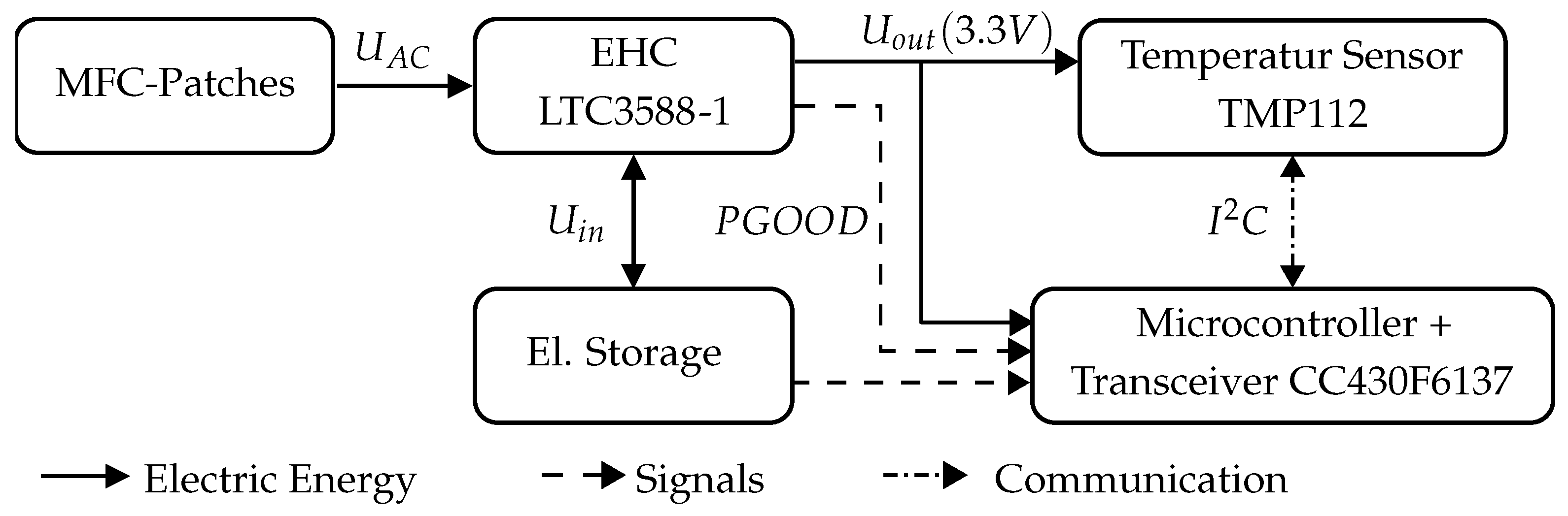
Figure 9 shows the elements of the system, starting with the PM in the form of the MFC patches generating an alternating voltage  U A C , which is modified by the EHC. For the EHC in the given example, the LTC3588-1 [34] is used, including a full-wave bridge rectifier and a buck converter to regulate the output voltage  U o u t .
In addition to the LTC3588-1, a capacitor as storage is added, storing the rectified voltage of the MFC patches. The state of charge of the capacitor is measured by the corresponding voltage  U i n  of the capacitor. The capacity
C = Q / U
of the storage, defined by the charge Q and the operating voltage U, depends on the loads powered and the operating strategy of the sensor. The loads are the LTC3588-1, a fully integrated temperature sensor TMP112 and a microcontroller ( μ C). The LTC3588-1 has constant current consumption of  I L T C = 81  nA for a selected output voltage of  U o u t = 3.3  V. For one measurement of the temperature and the transmission of the data, the sensor and  μ C combined consume a charge of  Q m e a s u r e = 219 μ As. Thus, the total charge of the loads for one measuring cycle,
Q l o a d s = I L T C × T + Q m e a s u r e = 82 nA × 1 s + 219 μ As = 219.082 μ As
with the measuring interval  T = 1  s, is calculated. The consumption of the LTC3588-1 and the sensor system is the consumption measured by [22] and includes energy losses. Further, the capacitor should be able to provide the charge for two measuring cycles. The operating voltage of the capacitor is limited by the EHC. With an operating voltage of  U i n 5.05  V, the buck converter sets the lower limit. Cutting  U i n > 20  V with a Zener diode to protect the components of the EHC from over-voltage, the LTC3588-1 sets the higher limit. With this, the minimum capacity
C s t o r , m i n = 2 × 219.082 μ As 20 V 5.05 V = 29.3 μ F C s t o r = 32 μ F
can be calculated. Besides the calculation of  C s t o r , a closer examination of the logic of the LTC3588-1 is necessary to determine the sensor’s operating strategy. As described before, the buck converter is activated when  U i n 5.05  V and then regulates  U o u t  to the targeted 3.3 V. Reaching  U o u t = 3.3  V, which is indicated by the LTC3588-1 sending the logical output  P G O O D = 1 , the  μ C is activated and monitors the capacitor’s state of charge. The sensor is enabled upon reaching  U i n = 20  V, corresponding to fully charged storage, and is measures henceforth with  T = 1  s. The deactivation of the sensor occurs when  U i n  drops below 11.89 V, because one measuring cycle leads to a drop of
Δ U i n = Q m e a s u r e C s t o r = 219.082 μ As 32 μ F = 6.84 V
and this results in  U i n < 5.05  V, with the consequence of the deactivation of  μ C and the buck converter. The measurement is started again after the capacitor is fully charged.
With all parameters set, the method is applied. The dimensions of the shaft as well as the mechanical loads for the PM are calculated. The calculated data for the homogenized MFC patch are given in Table A1, and Table A2 shows all dimensions of the MFC patch. The shaft is shown in Figure A1, with all parameters listed in 
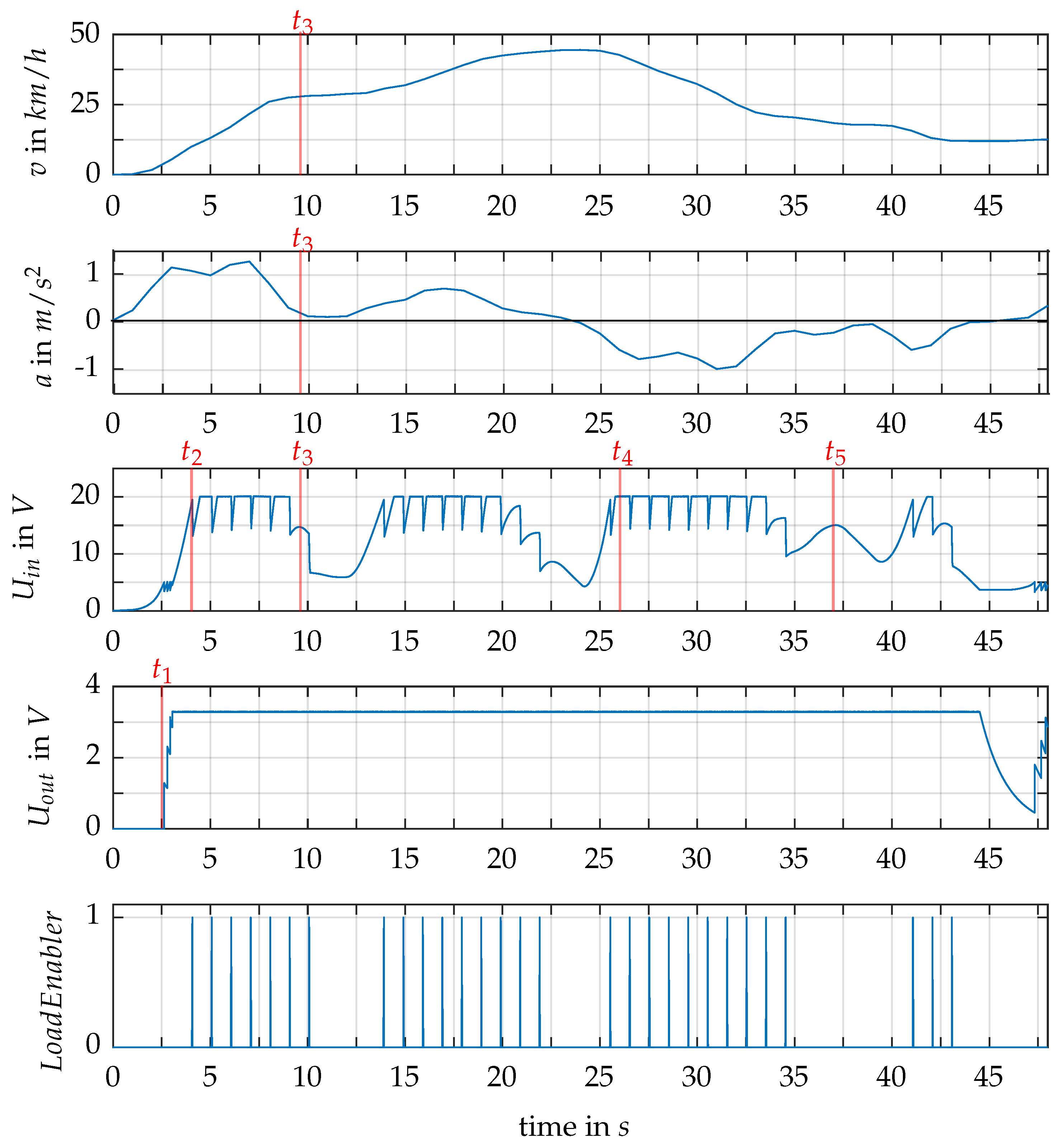
Table A3. In the presented work, the first 45 s of the WLTP are investigated. The results are presented in Figure 10. The velocity v of the vehicle corresponding to the rotating speed  n E M  of the EM, in addition to the acceleration a representing the required torque  M E M  of the EM, is the input to the simulation. From v and a, the corresponding bending stresses due to the imbalance  σ b , U ( n E M )  and  σ b , F r a d ( n E M , M E M )  are calculated with  σ b , F r a d  alternating with a frequency of  n E M .
Besides the driving scenario represented by the velocity v and the acceleration a, Figure 10 shows the simulated voltage of the capacitor  U i n  and the output voltage  U o u t . Further, the  L o a d E n a b l e r  as a logical variable indicates the single measurements executed. In the following, key aspects of the simulated results are pointed out, showing the characteristics of the PEH system, especially of the EHC, and the feasibility of the PEH on the rotor shaft is reviewed by means of the achieved electric charge collected in the capacitor and the measuring cycles executed over the driving scenario.
Starting with the first characteristic point for the EHC  t 1 , the acceleration from zero to around 30 km/h leads to the activation of the buck converter, which then increases  U o u t  step-wise up to the targeted  3.3  V, enabling the start-up of the  μ C after 3 s, monitoring  U i n  from then on.
The requirement of a fully charged capacitor, to activate the sensor, is fulfilled at  t 2 ; therefore, the  μ C sends the logical signal  L o a d E n a b l e r = 1  and the drop in  U i n  by the calculated  Δ U i n = 6.84  V is perceivable.
A characteristic point that demonstrates the usefulness of the capacitor being able to store the amount of electrical charge to power the EHC and sensor for two measuring cycles is  t 3 . Here, the MFC patches generate 41.6  μ As in the time from the last measuring cycle and do not recharge the capacitor by the consumed charge; thus, the charge for the upcoming measurement is provided by the storage, but this causes the sensor to be switched off afterwards, and a fully charged capacitor is necessary to reactivate the sensor. Further,  t 3  illustrates the weakness of the PEH regarding a driving scenario with a constant velocity and minor acceleration.
However, the results show ranges in which the amount of generated energy by the MFC patches is higher than the energy that the PEH system is capable of storing, exemplified by  t 4 , with  U i n  reaching 20 V, leading the LTC3588-1 to cut the voltage. The resulting wasted energy illustrates the potential for optimization to enable the PEH system to use the full amount of energy provided by the MFC patches.
The need for further optimization regarding the operating strategy of the sensor is identified at  t 5 , where the amount of energy provided by the system corresponds to a voltage of  U i n = 15  V and thus enough to power one measuring cycle. However, due to the operating strategy of charging the storage fully after  U i n  has dropped below 11.68 V, the sensor is deactivated.

5. Discussion

In the development of EMs, prior studies have noted the importance of sensors measuring the physical parameters of the EM. In reviewing the literature, a need for sensors placed on the rotor of the machine is identified. Further, it becomes clear that the electrical power supply of the sensor is one major challenge in realizing its rotor-side placement. One possible solution is the application of energy harvesting systems, generating the required electrical power for a sensor.
This study aims to define a method for the design of a piezoelectric energy harvester, integrated within the rotor shaft. Investigating the design process of EMs, especially the rotor design, the study identifies a gap in the input data for PEH design between the provided and the needed data, based on the V-model. With this method, a pre-design of the rotor is accomplished, including a procedure to determine the mechanical imbalance of the rotor. The method is followed by a simulation model, calculating the power output of an energy harvesting system. The simulation deals with the back-coupling effect of piezoelectric materials, representing the nonlinear electronic components as a physical model. In combination with the FEM model for the PM, in the form of MFC patches, a co-simulation is implemented. Driving scenarios, like the WLTP, are used as inputs, defining the mechanical loads of the rotor and MFC patches.
In this work, the first 45 s of the WLTP are simulated. They provide the first indication of the feasibility of the implementation of PEHs on rotors. Overall, the results indicate that the MFC patches generate a sufficient amount of electrical energy to power a sensor, including wireless data transmission. This is reinforced by the fact that, during 66% of this scenario, the sensor is activated. Further, the results show the weak point of the system for driving scenarios with a constant driving speed in combination with low torque requests for the EM. Drawing on [19,22], the results of the method are verified by means of a comparison with the measured results of their work.
With the first approach to the design of a piezoelectric generator achieved, further research regarding the optimization of the system needs to be performed. Application strategies for the sensor in comparison with the operating strategy of the EHC represent one possible investigation. The influence on the achievable operating strategy of the sensor when changing the electrical storage capacity is one major aspect. The results of the simulation need to be validated by means of test bench measurements. For this, a possible test bench to measure the produced charge of the MFC patch under different loads is presented by Abdulkhaliq et al. [1]. Adapting the test bench from the work of Micek et al. [19] by integrating a rotor shaft calculated with the method presented in this work, including the EHC with the temperature sensor, would enable the validation of the results from the co-simulation. The presented work is a contribution to the field of energy harvesting. Introducing EH applications in EMs, the realization of various new sensor systems is achievable. Thus, with EH powering such sensors, an increase in the efficiency and reliability of EMs is achievable as their data enable functions like condition monitoring and predictive maintenance. Therefore, an approach for the design of a PEH is presented with a method predicated on standardized and recognized processes within the automotive industry. Further, the introduced approach is integrated within the overall vehicle design process. The method extends, compared to a cantilever beam as a PEH, the less researched field of directly mounted PEHs. Regarding the simulation of a PEH, the key strength of this study is the integration of a co-simulation model. Analytical methods for the calculation of the power output of the PEH are faster but are limited to linear electronic components, leading to incorrect values for the power output regarding nonlinear electronic components. Composed of an FEM model for the PM and a physical model for the electronic components, the co-simulation enables the integration of nonlinear components, which are included in the power electronics of the system, into the physical model. Further, the integration of an operating strategy for a sensor system is viable. In addition, the model transforms driving scenarios into mechanical stress for the PEH. The method can be applied throughout the entire design process of PEHs and is capable of providing an increase in the degree of detail.

Author Contributions

Conceptualization, L.B.; methodology, L.B.; software, L.B. and D.H.; validation, L.B.; formal analysis, L.B.; investigation, L.B. and D.H.; resources, L.B.; data curation, L.B.; writing—original draft preparation, L.B.; writing—review and editing, L.B. and D.H.; visualization, L.B.; supervision, H.-C.R.; project administration, H.-C.R.; funding acquisition, H.-C.R. All authors have read and agreed to the published version of the manuscript.

Funding

This research received no external funding.

Data Availability Statement

The original contributions presented in the study are included in the article, further inquiries can be directed to the corresponding author.

Conflicts of Interest

The authors declare no conflicts of interest.

Abbreviations

EMElectric machine
EHEnergy harvesting
PEHPiezoelectric energy harvester
PMPiezoelectric material
MFCMacro-fiber composite
NASANational Aeronautics and Space Administration
EHCEnergy harvesting circuit
TRVTorque per rotor volume
MAPDLMechanical Ansys Parametric Design Language
WLTPWorld Harmonized Light Vehicle Test Procedure

Appendix A

Table A1. Parameters of the MFC patch.
ParameterVariableValueUnit
Density ρ 5.44g/cm3
Piezoelectric coefficient d 33 400pC/N
Piezoelectric coefficient d 31 170 pC/N
Poisson number υ 12 0.31 -
Poisson number υ 21 0.16 -
Poisson number υ 23 0.44 -
Elastic modulus E 1 30.336 GPa
Elastic modulus E 2 15.857 GPa
Shear modulus G 12 5.515 GPa
Table A2. Dimensions of the MFC patch.
ParameterVariableValueUnit
Length l M F C 37mm
Width w M F C 18mm
Table A3. Dimensions of the calculated shaft.
VariableValueUnit
Diameter d 11 28.8mm
d 12 44.6mm
d a 60.6mm
d 22 38.8mm
d 21 17.2mm
Length l 11 = l 21 67.9mm
l 12 = l 22 20mm
l a 175.8mm

Appendix B

Figure A1. Draft of the calculated shaft.
Energies 17 01884 g0a1

References

  1. Abdulkhaliq, H.S.; Crawley, F.; Luk, P.; Luo, Z. Piezoelectric Energy Harvester for Harnessing Rotational Kinetic Energy through Linear Energy Conversion. Energies 2023, 16, 6504. [Google Scholar] [CrossRef]
  2. Vaimann, T.; Kallaste, A. Condition Monitoring of Electrical Machines. In Proceedings of the 11th International Symposium “Topical Problems in the Field of Electrical and Power Engineering”, Pärnu, Estonia, 16–21 January 2012; pp. 209–212. [Google Scholar]
  3. Meng, T.; Zhang, P. A Review of Thermal Monitoring Techniques for Radial Permanent Magnet Machines. Machines 2022, 10, 18. [Google Scholar] [CrossRef]
  4. Antonino-Daviu, J. Electrical Monitoring under Transient Conditions: A New Paradigm in Electric Motors Predictive Maintenance. Appl. Sci. 2020, 10, 6137. [Google Scholar] [CrossRef]
  5. Lu, B.; Durocher, D.B.; Stemper, P. Predictive maintenance techniques. IEEE Ind. Appl. Mag. 2009, 15, 52–60. [Google Scholar] [CrossRef]
  6. Dettinger, F.; Jazdi, N.; Weyrich, M.; Brandl, L.; Reuss, H.C.; Pecha, U.; Parspour, N.; Li, S.; Frey, M.; Gauterin, F.; et al. Machine-Learning-Based Fault Detection in Electric Vehicle Powertrains Using a Digital Twin. In Proceedings of the 23rd Stuttgart International Symposium, Stuttgart, Germany, 4–5 July 2023; SAE International: Warrendale, PA, USA. [Google Scholar] [CrossRef]
  7. Baumann, M.S.; Steinboeck, A.; Kemmetmüller, W.; Kugi, A. Indirekte Schätzung der Magnettemperatur einer Permanentmagnet-Synchronmaschine. Automatisierungstechnik 2023, 71, 599–611. [Google Scholar] [CrossRef]
  8. Oudenhoven, J.F.M.; Vullers, R.J.M.; van Schaijk, R. A review of the present situation and future developments of micro-batteries for wireless autonomous sensor systems. Int. J. Energy Res. 2012, 36, 1139–1150. [Google Scholar] [CrossRef]
  9. Al Hadad, M. Rotating and non-rotating sensors for improving condition monitoring of wind turbines. In Proceedings of the 9th Australasian Congress on Applied Mechanics (ACAM9), Sydney, Australia, 27–29 November 2017. [Google Scholar]
  10. Brandl, L.; Sauerwald, R.; Reuss, H.C. Wireless Power Transmission for Powering a Sensor Placed at an Electrical Traction Machine with External Rotor. In Proceedings of the 23. Internationales Stuttgarter Symposium, Stuttgart, Germany, 4–5 July 2023; Kulzer, A.C., Reuss, H.C., Wagner, A., Eds.; Springer: Wiesbaden, Germany, 2023; pp. 187–203. [Google Scholar]
  11. Doolan Fernandes, J.; Carvalho Souza, F.E.; Cipriano Maniçoba, G.G.; Salazar, A.O.; de Paiva, J.A. Wireless Monitoring of Induction Machine Rotor Physical Variables. Sensors 2017, 17, 2660. [Google Scholar] [CrossRef] [PubMed]
  12. Hezekiah, J.D.K.; Ramya, K.C.; Radhakrishnan, S.B.K.; Kumarasamy, V.M.; Devendran, M.; Ramalingam, A.; Maheswar, R. Review of Next-Generation Wireless Devices with Self-Energy Harvesting for Sustainability Improvement. Energies 2023, 16, 5174. [Google Scholar] [CrossRef]
  13. Infineon Technologies, AG. TLE4971 Datasheet. Available online: https://www.infineon.com/dgdl/Infineon-TLE4971T-DS-DataSheet-v01_00-EN.pdf?fileId=8ac78c8c8779172a018799e3198002e7&_gl=1*ahp703*_up*MQ..&gclid=EAIaIQobChMIybqpz9WMhQMVOLCDBx1vNQJTEAAYASAAEgJZyPD_BwE&gclsrc=aw.ds (accessed on 22 March 2024).
  14. American Electronic Components. TMR2301 Datasheet. Available online: https://www.aecsensors.com/components/com_virtuemart/shop_image/product/Magnetic-Tunnelling-Magnetoresistive-TMR-Linear-Sensors/pdfs/TMR2301-Datasheet-EN-V1.0a.pdf (accessed on 22 March 2024).
  15. Texas Instruments. TMP119 Datasheet. Available online: https://www.ti.com/lit/ds/symlink/tmp119.pdf?ts=1711276824660&ref_url=https%253A%252F%252Fwww.ti.com%252Fproduct%252Fde-de%252FTMP119 (accessed on 22 March 2024).
  16. Maier, M.; Parspour, N. Operation of an Electrical Excited Synchronous Machine by Contactless Energy Transfer to the Rotor. IEEE Trans. Ind. Appl. 2018, 54, 3217–3225. [Google Scholar] [CrossRef]
  17. Erturk, A.; Inman, D.J. (Eds.) Piezoelectric Energy Harvesting, 1st ed.; Wiley: Chichester, UK, 2011. [Google Scholar]
  18. Daukaev, K.; Rassõlkin, A.; Kallaste, A.; Vaimann, T.; Belahcen, A. A review of electrical machine design processes from the standpoint of software selection. In Proceedings of the 2017 IEEE 58th International Scientific Conference on Power and Electrical Engineering of Riga Technical University (RTUCON), Riga, Latvia, 12–13 October 2017; pp. 1–6. [Google Scholar] [CrossRef]
  19. Micek, P.; Grzybek, D. Wireless stress sensor based on piezoelectric energy harvesting for a rotating shaft. Sens. Actuators A Phys. 2020, 301, 111744. [Google Scholar] [CrossRef]
  20. Priya, S. (Ed.) Energy Harvesting Technologies; Springer: New York, NY, USA, 2010. [Google Scholar]
  21. Smart Materials. Macro Fiber Composite Datasheet. Available online: https://www.smart-material.com/media/Datasheets/MFC_V2.4-datasheet-web.pdf (accessed on 22 January 2024).
  22. Dembowski, K. (Ed.) Energy Harvesting für die Mikroelektronik: Energieeffiziente und -Autarke Lösungen für Drahtlose Sensorsysteme; VDE: Berlin/Offenbach, Germany, 2011. [Google Scholar]
  23. VDI The Association of German Engineers. VDI/VDE 2206: Development of Mechatronic and Cyber-Physical Systems; VDI: Düsseldorf, Germany, 2021. [Google Scholar]
  24. Lei, G.; Zhu, J.; Guo, Y. (Eds.) Multidisciplinary Design Optimization Electrical Machines and Drive Systems; Springer: Berlin, Germany, 2016. [Google Scholar]
  25. Müller, G.; Vogt, K.; Ponick, B. (Eds.) Berechnung Elektrischer Maschinen, 6. Völlig Neu Bearbeitete Auflage; Elektrische Maschinen; Wiley-VCH: Weinheim, Germany, 2008; Volume 2. [Google Scholar]
  26. DIN 743; Calculation of Load Capacity of Shafts and Axles. DIN German Institute for Standardization: Berlin, Germany, 2012.
  27. DIN ISO 21940; Mechanical Vibration-Rotor Balancing. DIN German Institute for Standardization: Berlin, Germany, 2019.
  28. Schneider, H. Auswuchttechnik, 8. Neu Bearbeitete Auflage, 2013 ed.; Springer eBook Collection Imprint; Springer Vieweg: Berlin/Heidelberg, Germany, 2013. [Google Scholar]
  29. Elvin, N.G.; Elvin, A.A. A Coupled Finite Element—Circuit Simulation Model for Analyzing Piezoelectric Energy Generators. J. Intell. Mater. Syst. Struct. 2009, 20, 587–595. [Google Scholar] [CrossRef]
  30. Gedeon, D.; Rupitsch, S.J. Finite element based system simulation for piezoelectric vibration energy harvesting devices. J. Intell. Mater. Syst. Struct. 2018, 29, 1333–1347. [Google Scholar] [CrossRef]
  31. Deraemaeker, A.; Nasser, H.; Benjeddou, A.; Preumont, A. Mixing Rules for the Piezoelectric Properties of Macro Fiber Composites. J. Intell. Mater. Syst. Struct. 2009, 20, 1475–1482. [Google Scholar] [CrossRef]
  32. Kuang, Y.; Zhu, M. Evaluation and validation of equivalent properties of macro fibre composites for piezoelectric transducer modelling. Compos. Part B Eng. 2019, 158, 189–197. [Google Scholar] [CrossRef]
  33. United Sates Department of Energy. FY 2016 Annual Progress Report for Electric Drive Technologies Program; United Sates Department of Energy: Washington, DC, USA, 2016.
  34. Linear Technology. LTC 3588-1 Datasheet. Available online: https://www.analog.com/media/en/technical-documentation/data-sheets/35881fc.pdf (accessed on 22 January 2024).
Figure 1. Energy harvesting system based on [20].
Energies 17 01884 g001
Figure 2. Schematic rotor shaft: (a) side view, (b) front view.
Energies 17 01884 g002
Figure 3. V-model based on [18,23].
Energies 17 01884 g003
Figure 5. Rotor shaft after first draft.
Energies 17 01884 g005
Figure 6. Imbalance of rotor [28].
Energies 17 01884 g006
Figure 7. Imbalance torque of rotor [28].
Energies 17 01884 g007
Figure 8. Approach for determination of imbalance.
Energies 17 01884 g008
Figure 9. Energy harvesting system with temperature sensor based on [22].
Energies 17 01884 g009
Figure 10. Simulation results for the energy harvesting system.
Energies 17 01884 g010
Table 1. Power consumption of possible sensors for EMs.
SensorCurrent in mAPower in mW
Current sensor [13]1859.5
Hall sensor [14]0.20.2
Temperature sensor [15]0.20.3
Table 2. Provided data as input in the shaft design.
SubsystemExplanationVariableUnit
Data from vehicle designMax. rotating speed EM n m a x 1/min
Required max. torque EM M t a r Nm
Data from EM designDiameter active area rotor d A mm
Inner diameter active area rotor d a mm
Length active area rotor l a mm
Table 3. Input data for first draft of the shaft based on the BMW i3 [33].
SubsystemExplanationVariableValueUnit
Data from vehicle designMax. rotating speed EM n m a x 11401/min
Required max. torque EM M t a r 250Nm
Data from EM designDiameter active area rotor d A 178.6mm
Inner diameter active area rotor d a 60.4mm
Length active area rotor l a 175.8mm
Disclaimer/Publisher’s Note: The statements, opinions and data contained in all publications are solely those of the individual author(s) and contributor(s) and not of MDPI and/or the editor(s). MDPI and/or the editor(s) disclaim responsibility for any injury to people or property resulting from any ideas, methods, instructions or products referred to in the content.

