Abstract
This paper presents a design study focusing on the thermal safety of an induction motor integrated with a pump unit, which operates submerged in liquefied natural gas (LNG) in the LNG tanks of LNG carrier ships ranging from 150 K to 200 K cubic meters (CBM). In this study, we carried out the electromagnetic design of the induction motor and verified the thermal safety against a temperature increase due to losses during the motor operation through thermal fluid analysis, taking into account the discharge flow of the emergency pump and the air gap of the motor. In the electromagnetic design, the resistivity of the stator winding copper conductors and the rotor aluminum bars, which act as important design constants for the rated operating and starting characteristics of the induction motor in cryogenic temperature environments, reflects the characteristic of linearly changing with the temperature. In cryogenic environments, the reduction in the resistance of the rotor bars of the induction motor leads to a decrease in the starting torque characteristics. Therefore, the shape optimization design of the rotor bar was performed to improve the starting torque characteristics, and 2D electromagnetic analysis was performed on the magnetic flux density distribution and magnetic saturation using Ansys Electromagnetics 16.0. After the electromagnetic design, a 3D thermal flow analysis was conducted using Ansys Fluent 17.0, considering the stator iron losses, rotor bar losses, stator and rotor iron losses, and stray load losses as heat sources. The flow analysis aimed to analytically verify the thermal safety concerning the vaporization of the LNG flowing through the emergency pump’s discharge flow path and the motor’s internal air gap. The motor was manufactured, and the rated and starting operating characteristics of the motor were measured under LN2 submerged conditions according to the IEEE 112 F1 method, to validate whether the performance characteristics met the specifications’ requirements. Subsequently, the thermal safety of the motor was finally verified through a temperature increase test under LNG submerged conditions after assembling it with the emergency pump.
1. Introduction
The increasing demand for clean fuels and heightened international awareness of environmental pollution prevention, driven by global environmental regulations and diversification policies in energy resources, have led to growing interest in alternative fuels. Among these alternatives, LNG (liquefied natural gas) is gaining prominence due to its comparatively lower cost and abundant reserves, resulting in a surge in demand. Additionally, with stricter environmental regulations, particularly in emission control areas, the demand for LNG as a fuel for ships is rising. The growing demand for LNG has made LNG production facilities, transportation, and supply pivotal topics in the energy and shipbuilding industries [1,2,3,4,5]. With the continuous advancement of science and technology, cryogenic technology is widely utilized across various industries such as shipbuilding, aerospace, thermonuclear fusion, and defense. Cryogenic liquid pumps have broad applications, including the transportation of liquefied natural gas and liquid hydrogen [6]. Among them, the emergency pump is a pump used to unload LNG from LNG carriers to onshore terminals in exporting countries in the event of abnormal or malfunctioning conditions in the main cargo pump.
Previous research focused on the conventional design method of the typical three-phase induction motor operating at room temperature and the analysis of the torque characteristics for the induction motor according to temperature variations. In previous research on the design of cryogenic induction motors, the primary electromagnetic design was conducted under normal temperature conditions. Subsequently, a study was conducted to reduce the size of the motor by adjusting the size of the stator winding conductors, stator slot sizes, rotor aluminum bar sizes, and rotor slot sizes to achieve resistance values similar to those obtained in the primary electromagnetic design. Furthermore, comparative studies on the operating characteristics of the motor under room and cryogenic temperature conditions were conducted. The thermal analysis study for thermal safety verification was conducted by considering only the copper losses in the stator winding as the heat source, excluding heat generation from iron losses in the core and losses in the rotor bar. Additionally, the flow rate of LNG through the motor’s air gap and the main flow path of the pump was not considered [7,8,9,10,11].
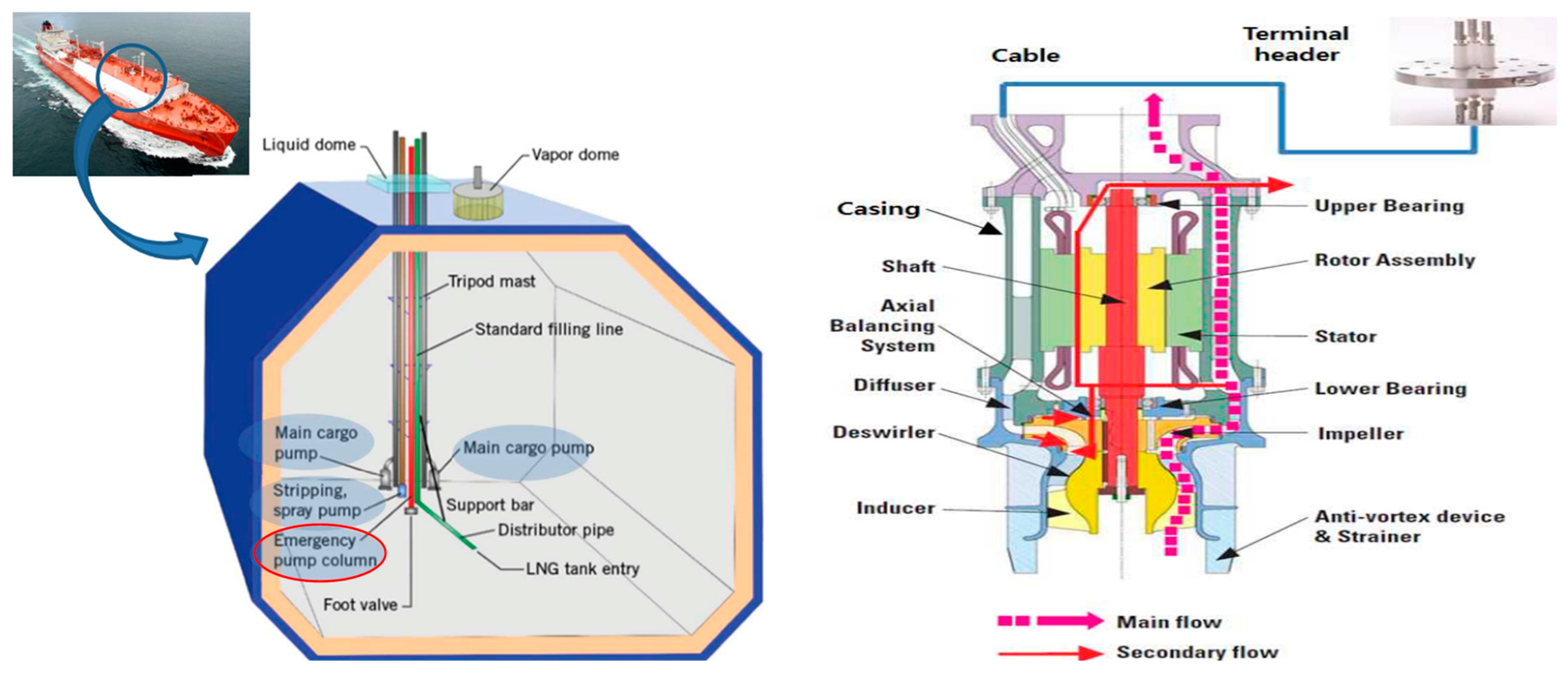
The emergency pump, as depicted in Figure 1, operates submerged in LNG with the motor and pump integrated into one unit. Furthermore, it features a structure including the main flow path of the emergency pump and the secondary flow path within the motor’s air gap where LNG flows.
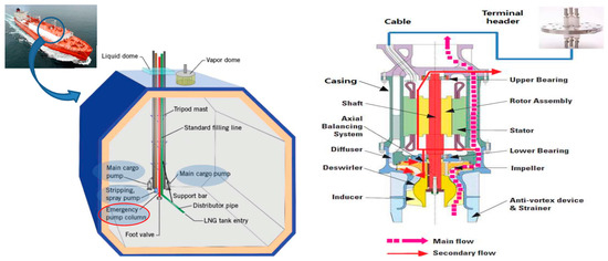
Figure 1.
LNG tank on LNG carrier ship and configuration of emergency pump.
In this paper, the electromagnetic design was conducted considering the change in the material properties of the stator winding copper and rotor aluminum bars of the induction motor operating in LNG at −163 °C. To validate the feasibility of the electromagnetic design, thermal flow analysis was conducted to interpret the temperature increase in the LNG flowing through the main flow path of the pump and the air gap of the motor. Additionally, to improve the low starting torque characteristics due to operation in cryogenic fluids, design optimization was performed through the rotor bar shape ratio. After the design, the motor was manufactured, and its rated and starting characteristics were evaluated under LN2 submerged conditions according to the IEEE 112 F1 method [12]. Subsequently, temperature increase tests were conducted under LNG immersion conditions after assembling the emergency pump.
2. Design of Cryogenic Induction Motor for Operating Emergency Pump
2.1. Electromagnetic Design and Analysis of the Induction Motor
Pn, Eff, PF, Lstk, Dg, W1, , , , , and are the rated output, rated efficiency, rated power factor, core length, stator’s inner diameter, number of turns, stator winding resistance, rotor aluminum bar resistance, stator leakage reactance, rotor leakage reactance, and magnetization reactance.
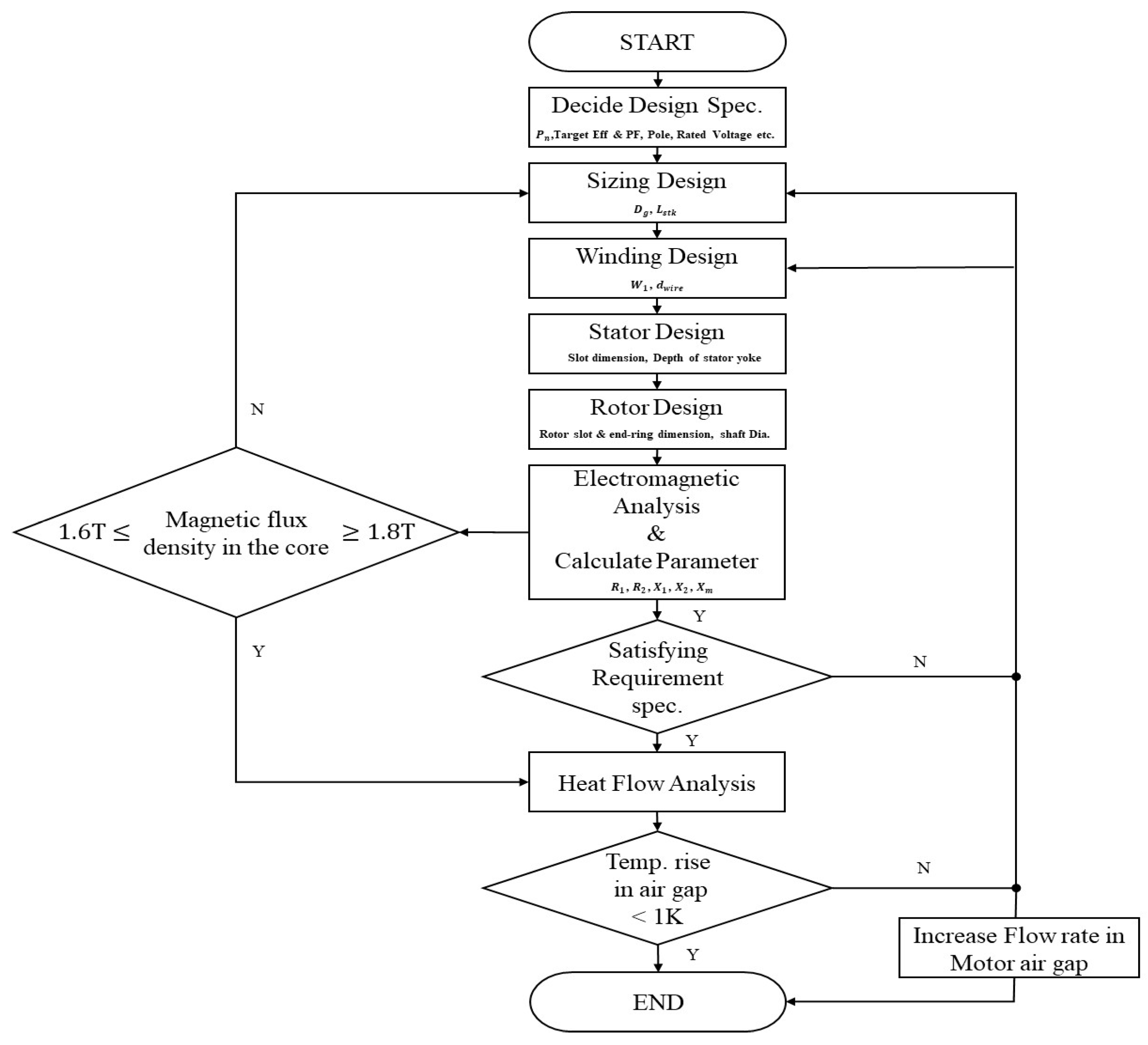
The design of the cryogenic submerged induction motor was carried out according to the design flow chart in Figure 2.
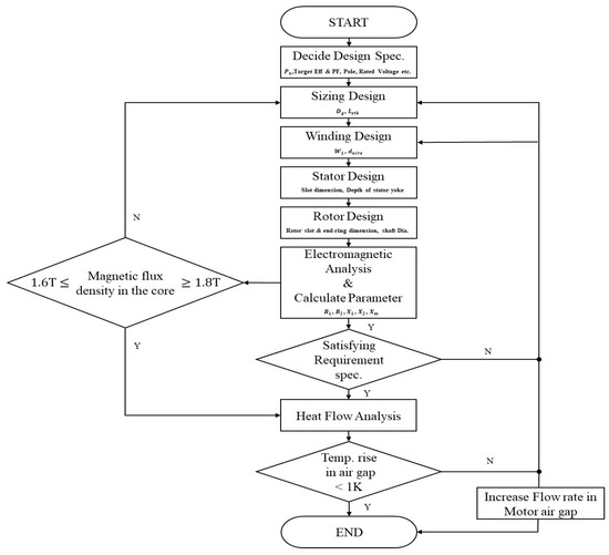
Figure 2.
Design flow chart.
Firstly, the rated output, target efficiency, power factor, and number of poles should be determined as design specifications. Then, considering the Direct on Line (DOL) starting condition, limits on the starting torque and starting current should be determined. In this paper, the rated output of the motor was determined as 200 kW, considering a 10% margin on the brake horsepower (BHP) of the pump according to the design specifications of the emergency pump, as shown in Table 1, following the API610 standard. Additionally, to ensure trouble-free operation during the startup of the emergency pump, the design requirements for the starting torque and starting current were provided, as shown in Table 2.

Table 1.
Specification of emergency pump.
Table 2.
Requirement specification of the induction motor.
Considering the condition where the motor is installed integrally inside the emergency pump, the main sizing design of the motor involved setting constraints on the stator’s outer diameter to be 388 mm and the core length to be less than or equal to 340 mm. Therefore, using Equation (1) and the recommended dimensional ratio from Table 3 based on the number of poles, since the number of poles according to the rotating speed was two poles, the stator’s inner diameter was determined to be 249 mm [9].
where , Lstk, p1, and Dg are the pole pitch, core length, pole pair, and stator’s inner diameter.
Table 3.
Aspect ratio of induction motor as the number of poles.
The number of stator slots was determined to be 42 slots based on the number of poles, while the number of rotor slots was chosen to be approximately 15% less, at 36 slots, to reduce stray load losses. In the winding design, the number of series turns of the stator were designed considering the magnetic flux generated per pole according to the air gap magnetic flux density [13,14,15,16].
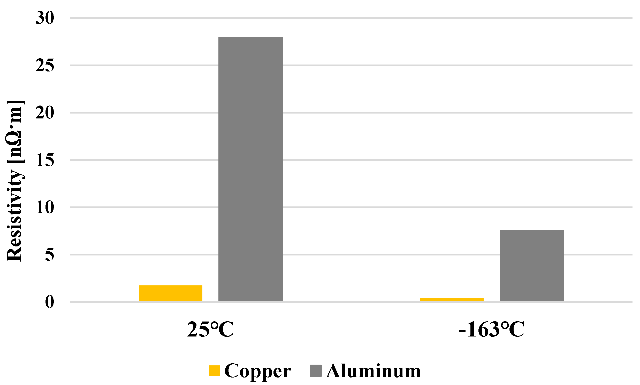
As shown in Figure 3, to reduce the harmonics of magnetic flux in the air gap, the winding of one phase was distributed across seven slots based on the combination of the number of slots per pole, and a 16/21 short pitch winding was applied. By applying a 16/21 short pitch winding, the fifth harmonic was reduced by 86.8%, and the seventh harmonic was reduced by 64.3%. The temperature variation in the resistivity of the copper conductor, as depicted in Figure 4 and Equation (2), was applied to the sizing design of the coil and the stator design.
where , , , , and are the resistivity at degrees Celsius, the resistivity at zero degrees Celsius, the temperature coefficient of resistivity, the temperature at , and the temperature at zero degrees Celsius, respectively.
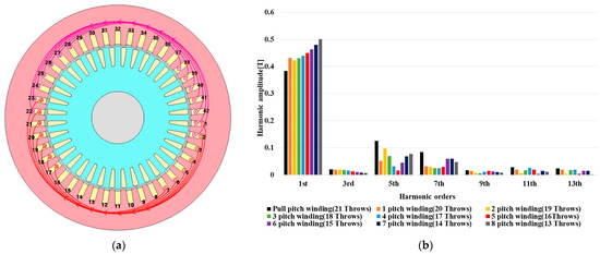
Figure 3.
(a) Final distributed short pitch of one-phase winding; (b) FFT analysis results of harmonics in air gap magnetic flux according to winding pitch.

Figure 4.
Resistivity characteristics compared at different temperatures.
Since cryogenic motors operate submerged in LNG fluid at −163 °C, it is necessary to improve the starting torque characteristics with low rotor aluminum bar resistance due to the cryogenic temperature. The torque of an induction motor can be calculated as Equation (3).
where , , , s, , , , , and are the phase voltage, stator winding resistance, rotor aluminum bar resistance, slip, stator leakage reactance, rotor leakage reactance, magnetization reactance, number of pole pairs, and angular velocity.
In previous studies on the design of cryogenic motors, the resistance of the rotor aluminum bar was reduced to improve the low starting torque characteristics by applying a slot size reduction design that considers changes in resistance with the temperature in the rotor slot area applied in room temperature designs [8,11]. To improve the starting torque characteristics under cryogenic conditions, increasing the resistance of the rotor’s aluminum bars through rotor slot reduction may lead to increased losses in the rotor’s aluminum bar, potentially causing efficiency reduction issues.
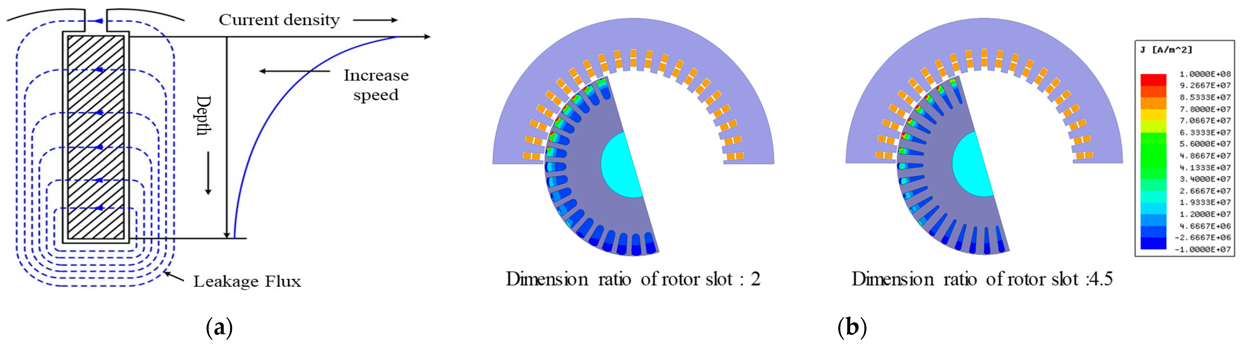
In this paper, deep slots were used to improve the starting torque characteristics, considering the liquefied natural gas installation environment. As shown in Figure 5, the deeper the slots, the larger the leakage reactance inside the rotor slots. During startup, since slip is significant, the leakage reactance is larger than during the rated operation. Therefore, the current is concentrated on the surface of the rotor bar, resulting in a similar effect to increased rotor resistance. This corresponds to a reduction in the area through which current flows in the rotor aluminum bar, resulting in an increase in rotor resistance during startup. Therefore, in this study, an optimization design of the rotor slot considering the Deep Bar Effect was conducted, aiming to minimize the reduction in the rotor slot and improve the starting torque, rather than simply reducing the rotor slot [17].
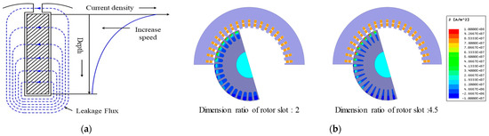
Figure 5.
(a) Leakage flux and current density distribution in deep bar; (b) starting current density distribution of the rotor bars based on dimension ratio of rotor slot.
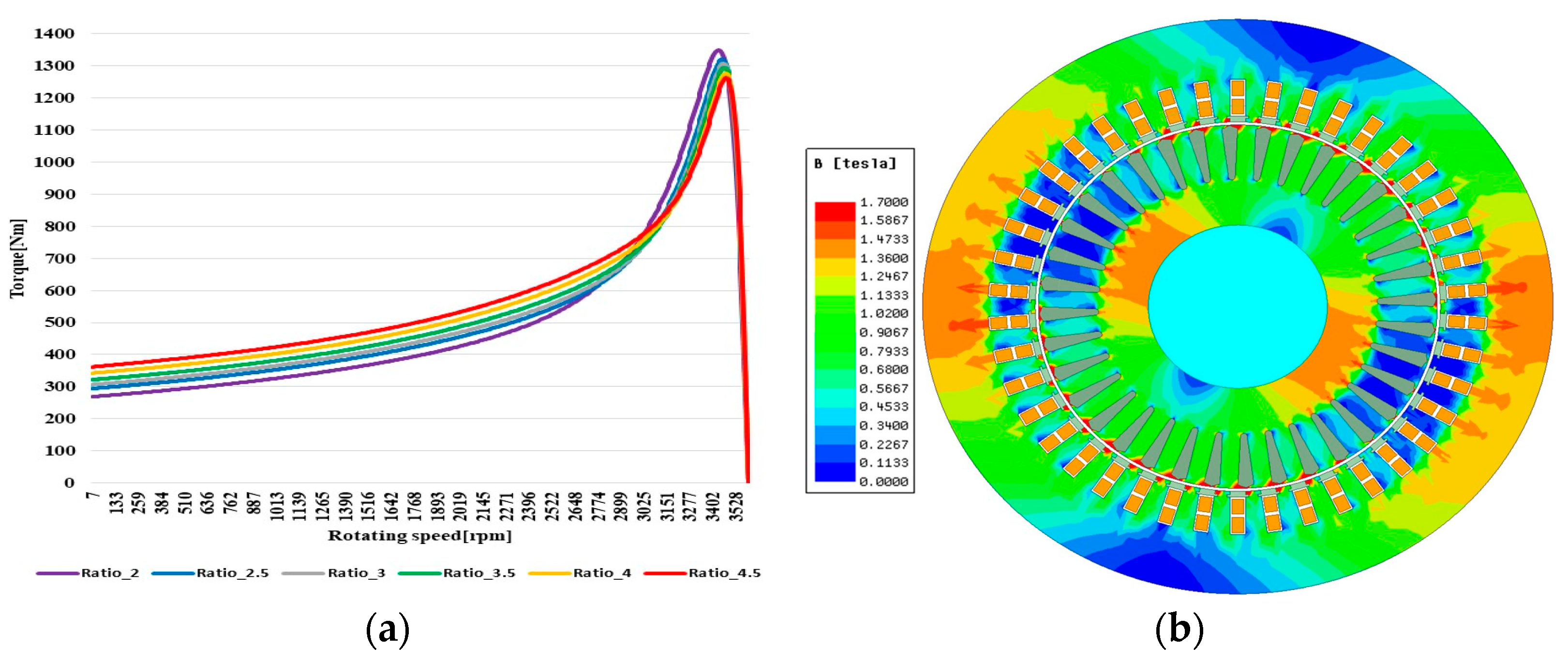
When the dimension ratio between the rotor slot width and length was set to 2, 2.5, 3, 3.5, 4, and 4.5, it was observed that the starting torque increased as the dimension ratio increased. Specifically, there was a 17.4% improvement in the starting torque at a ratio of 4.5 compared to 2, as shown in Figure 6a. After considering the saturation of the stator and rotor magnetic flux density, the final design model was selected with a dimension ratio of 4.5, as depicted in Figure 6b. The design parameters of the final model are presented in Table 4.

Figure 6.
(a) Resistivity characteristics compared at different temperature; (b) magnetic flux density of final design model.
Table 4.
Design parameter of the final design model.
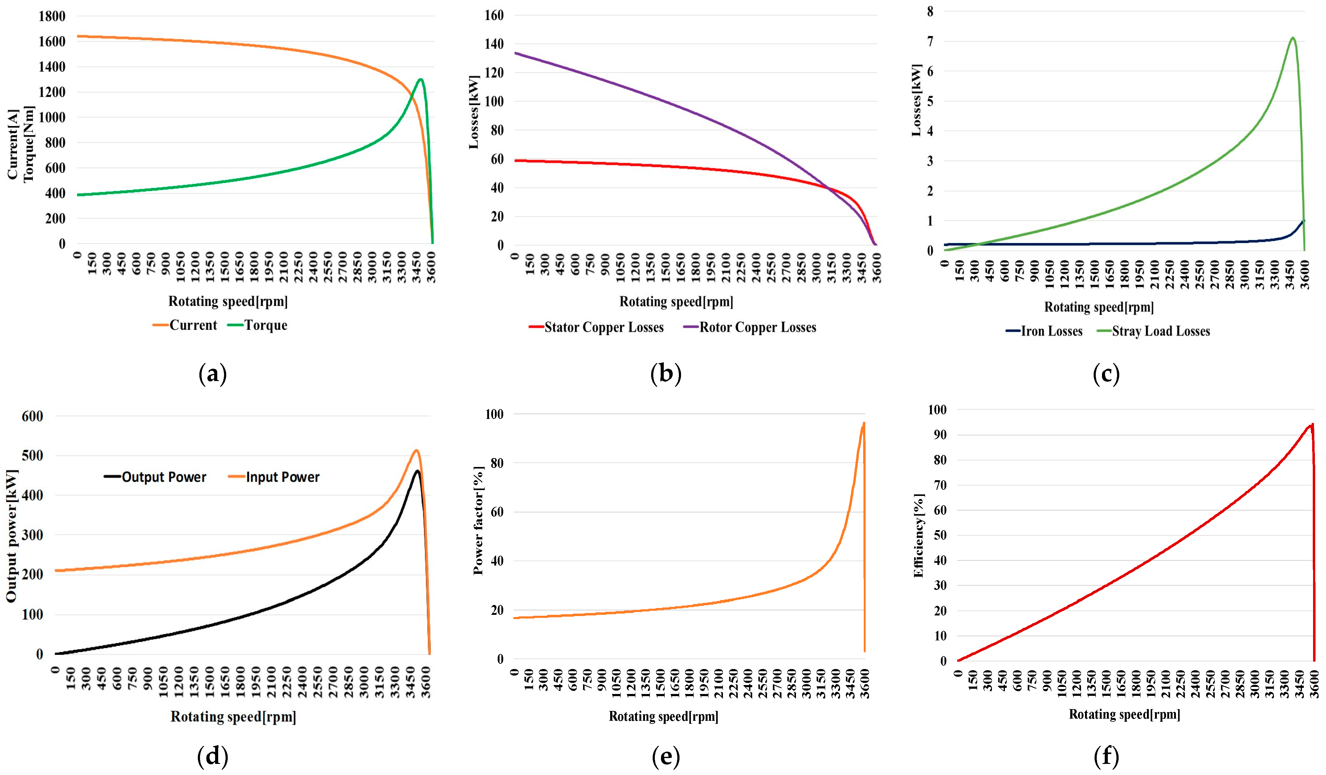
Figure 7 shows the performance characteristic curves of the final design model derived through electromagnetic analysis. The rated operating point of the final design model is 3574 rpm. The design performance characteristics at the rated operating point are the same as those in Table 5 and Table 6. Furthermore, Table 5 and Table 6 compare the electromagnetic analysis results of the rated and starting characteristics between the final design model of ratio 4.5 and the basic design model of ratio 2. While there is not a significant difference in the rated characteristics between the basic design model and the final design model, the starting torque of the final design model, which underwent optimized rotor dimension design to minimize the reduction in the rotor slots and improve the starting torque, is increased by 17.4%. The test results obtained from the no-load loss separation test were examined and evaluated to determine the friction loss, which was then applied in the design efficiency calculations. The stray load loss was calculated by applying 1.5% of the rated output as specified in IEEE 112.

Figure 7.
Characteristic curve of final design model based on rotating speed at −163 °C: (a) speed vs. current and torque curve; (b) speed vs. stator copper and rotor bar loss; (c) speed vs. iron loss and stray load loss; (d) speed vs. output and input power; (e) speed vs. power factor; (f) speed vs. efficiency.
Table 5.
Performance characteristics of basic design and final design model at rated point and −163 °C.
Table 6.
Starting characteristics of basic design and final design model at rated point and −163 °C.
2.2. Heat Flow Analysis
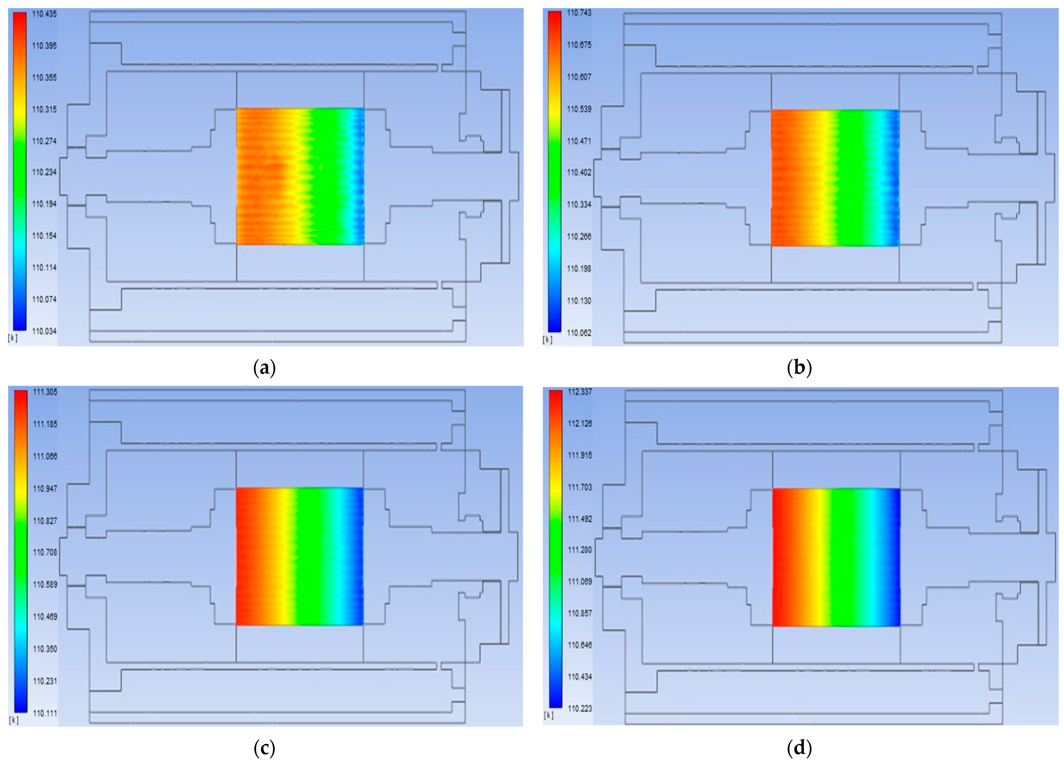
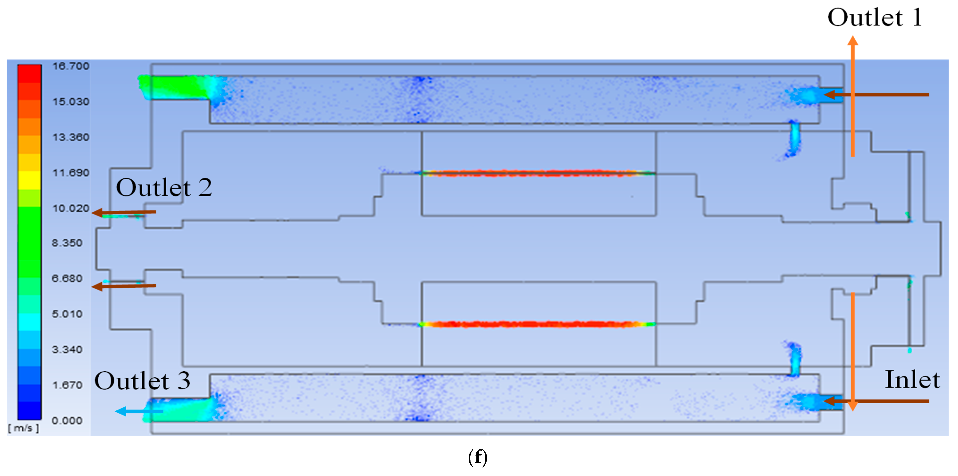
For the heat flow analysis, the motor’s stator winding losses, rotor bar losses, core losses, and stray load losses were applied as heat sources, and thermal safety verification was performed analytically considering the pump’s main flow path and LNG flowing in the motor’s air gap. For validating the adequacy of the motor design and ensuring thermal safety, thermal flow analysis was conducted under the condition where 1%, 0.75%, 0.5%, and 0.25% of the rated flow rate entered the secondary flow path (motor’s air gap), while the remaining flow rate flowed through the main flow path of the pump. The analysis conditions are as shown in Figure 8 and Table 7. The material properties were assumed to remain constant with temperature changes, and the heat source was applied to the stator winding losses, rotor bar losses, and iron losses. Stray load losses were applied to the core. The heat flow analysis results in the air gap are depicted in Figure 9. At 1% of the rated flow rate, the temperature was analyzed as 110.435 K (−162.565 °C). At 0.75%, it was 110.743 K (−162.257 °C), at 0.5%, it was 111.305 K (−161.695 °C), and at 0.25%, it was 112.337 K (−160.663 °C). Based on these results, decisions regarding the electromagnetic redesign of the motor should consider the temperature increase in the motor’s air gap, which varies depending on the flow rate through the secondary flow path. To ensure thermal safety, the final condition was set to 1%, and the analysis results at this condition are shown in Figure 10. The temperature rose by 4.25 K in the stator winding, as shown in Figure 10b, and the temperature rose by 3.94 K in the rotor aluminum bar, as shown in Figure 10c. Additionally, the temperature rose by 2.48 K in the stator core, as shown in Figure 10d, and the temperature rose by 2.24 K in the rotor core, as shown in Figure 10e. As shown in Figure 9a, there was little temperature increase in the air gap of the motor, with a temperature increase of 0.435 K.
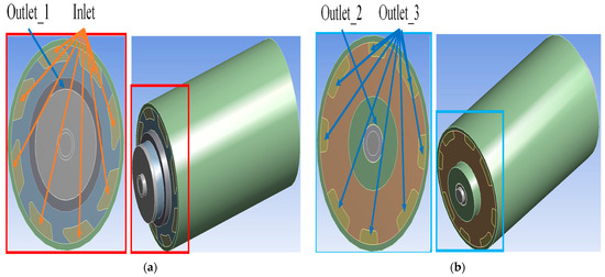
Figure 8.
Heat flow analysis model: (a) drive end side; (b) non-drive end side.
Table 7.
Heat flow analysis condition.
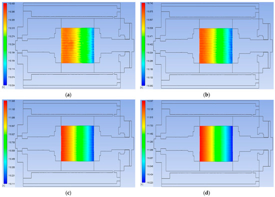
Figure 9.
Results of heat flow analysis in air gap according to the flow rate in the motor air gap: (a) 1% of the rated flow; (b) 0.75% of the rated flow; (c) 0.5% of the rated flow; (d) 0.25% of the rated flow.
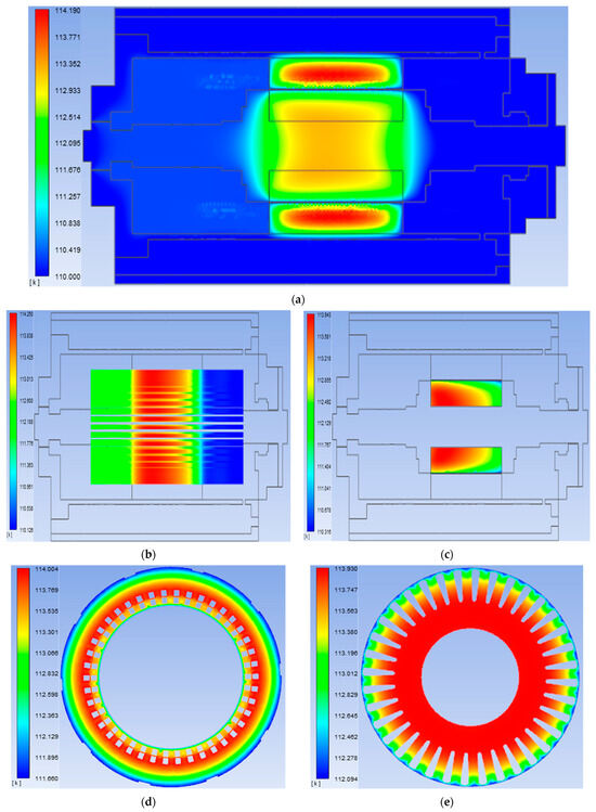
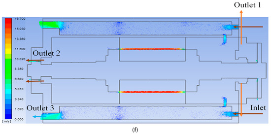
Figure 10.
Results of heat flow analysis: (a) central section of the entire analytical model; (b) stator wingding; (c) rotor bar; (d) stator core; (e) rotor core; (f) flow rate of entire analytical model.
3. Test Evaluation and Verification
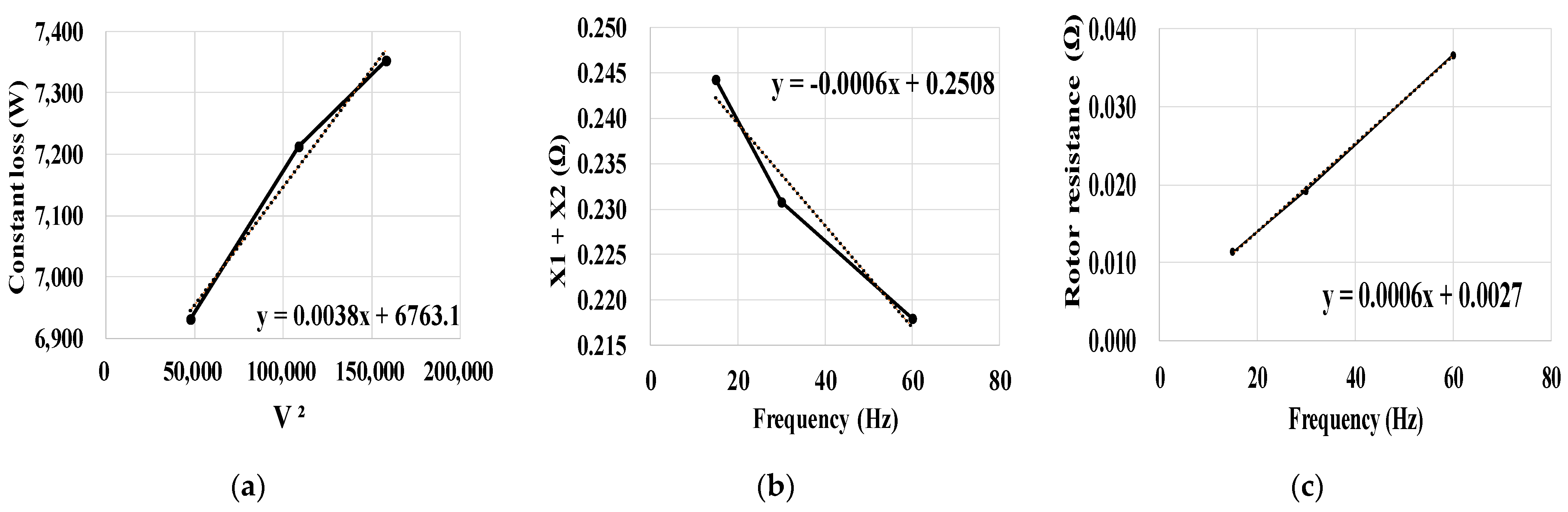
Figure 11a,b represent the land-based test system (LBTS) for evaluating the motor performance utilizing LN2 cryogenic fluid. The motor was fabricated as depicted in Figure 11d, and no-load loss separation testing was conducted according to the IEEE 112 F1 method using LBTS. Under the rated frequency and no-load conditions, test voltages corresponding to 125%, 100%, 90%, 75%, 50%, 35%, and 20% of the rated voltage were applied. The current, input power, stator winding resistance, and stator winding losses were measured at these conditions, and the friction losses and iron losses were separated [18]. The corresponding test data are presented in Table 8. The curve for the no-load loss separation is shown in Figure 12a.
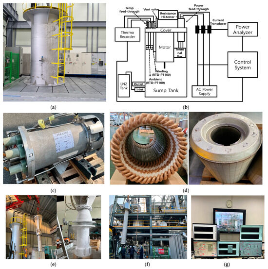
Figure 11.
Experimental setup for evaluating the performance and temperature increase test of the motor: (a) land-based test system (LBTS) for performance test; (b) configuration diagram of land-based test system (LBTS); (c) manufactured emergency pump; (d) manufactured stator and rotor of the motor; (e) installation of motor for performance test and motor appearance condition after performance test; (f) installation of pump for temperature increase test of motor; (g) pump performance data acquisition and control system.
Table 8.
Data of no-load test.
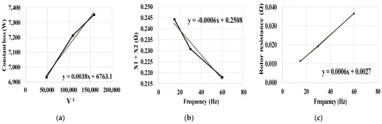
Figure 12.
Test results of no-load test and locked rotor test: (a) assumed friction loss curve; (b) total leakage reactance; (c) rotor resistance curve.
The reactance and rotor resistance were determined by the locked rotor test. The test is conducted by applying test frequencies corresponding to 100%, 50%, and 25% of the rated frequency while the rotor is locked, adjusting the test voltage to allow the rated current to be applied. The test data are provided in Table 9 [12]. The reactance curve and rotor resistance curve derived from the locked rotor test are shown in Figure 12b,c. The resistance of the stator winding and rotor bars, obtained through the no-load loss separation and locked rotor tests conducted using LN2 cryogenic fluid of −192 °C, was adjusted for −163 °C. Subsequently, the test results were found to meet the design requirements, and these results are presented in Table 10.
Table 9.
Data of locked rotor test.
Table 10.
Performance test result of the motor according to IEEE 112 F1 method at rated point and −163 °C.
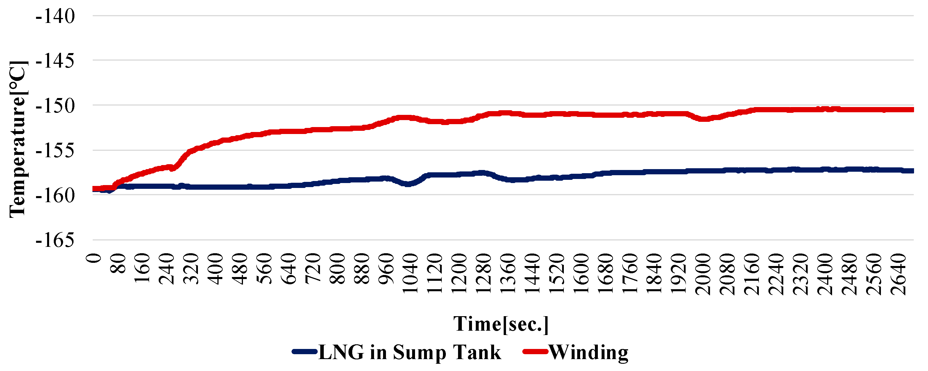
In the LNG cryogenic pump performance evaluation equipment shown in Figure 11f, a load test of the emergency pump using LNG cryogenic fluid was conducted. During this test, the temperature of the motor’s stator winding increased by 6.8 K, and the temperature increase graph is depicted in Figure 13.
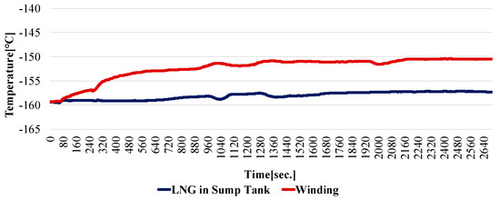
Figure 13.
Motor winding temperature increase curve during the load test of the emergency pump.
4. Conclusions
This paper presents the design of a cryogenic motor submerged in LNG. During the electromagnetic design phase, consideration was given to the changes in the material properties at cryogenic temperatures. In order to improve the low starting torque characteristics caused by the low rotor resistance in the operating environment submerged in LNG, we optimized the width and length of the rotor slot shape, considering the Deep Bar Effect. To minimize the reduction in the rotor slots, we aimed to enhance the starting torque without compromising efficiency. This optimization led to a 17.4% improvement in the starting torque compared to the initial design, without reducing the rotor slots to increase resistance.
To confirm the possibility of LNG vaporization occurring in the main flow path of the emergency pump and the secondary flow path within the motor, thermal flow analysis is necessary at the final design stage. Therefore, heat flow analysis, considering the stator winding copper losses, rotor bar losses, iron loss, and stray load losses as heat sources, was conducted. Through analytical validation, it was confirmed that there was no temperature increase in the LNG in the main flow path, and a temperature increase of 0.43 K occurred in the secondary flow path, the motor’s internal air gap. After the design, the motor was manufactured, and performance evaluation was conducted using LN2 cryogenic fluid in LBTS following the IEEE 1112 F1 method. This was performed to verify that the designed and manufactured motor met the performance requirements. Additionally, in the cryogenic pump performance equipment using LNG cryogenic fluid, the temperature increase in the stator winding was measured during actual pump load tests to verify the thermal safety of the motor.
Author Contributions
Conceptualization, J.L.; methodology, K.-P.H.; software, K.-P.H.; validation, K.-P.H.; formal analysis, K.-P.H.; investigation, K.-P.H.; writing—original draft preparation, K.-P.H.; writing—review and editing, J.L.; visualization, K.-P.H. All authors have read and agreed to the published version of the manuscript.
Funding
This work was fully supported by the material parts technology development of MOTIE (20022457).
Institutional Review Board Statement
Not applicable.
Informed Consent Statement
Not applicable.
Data Availability Statement
The original contributions presented in the study are included in the article, further inquiries can be directed to the corresponding author.
Conflicts of Interest
The authors declare no conflicts of interest.
References
- Tessarolo, A.; Zocco, G.; Tonello, C. Design and testing of a 45-MW 100-Hz quadruple-star synchronous motor for a liquefied natural gas turbo-compressor drive. IEEE Trans. Ind. Appl. 2011, 47, 1210–1219. [Google Scholar] [CrossRef]
- Dlugiewicz, L.; Kolowrotkiewicz, J.; Szelag, W.; Baranski, M.; Neumann, R. Electrical motor for liquid gas pump. In Proceedings of the International Symposium on Power Electronics, Electrical Drives, Automation and Motion (SPEEDAM), Taormina, Italy, 23–26 May 2006; pp. 311–316. [Google Scholar]
- Lee, H.; Kang, H. Comparative Life Cycle Assessments and Economic Analyses of Alternative Marine Fuels: Insights for Practical Strategies. Sustainability 2024, 16, 2114. [Google Scholar] [CrossRef]
- Jwaginga, J.; Pruyn, J. Optimal ship fuel selection under life cycle uncertainty. Sustainability 2024, 16, 1947. [Google Scholar] [CrossRef]
- Malukas, A. The Application of Cryogenic Carbon Capture Technology on the Dual-Fuel Ship through the Utilisation of LNG Cold Potential. Mar. Sci. Eng. 2024, 12, 217. [Google Scholar]
- Ai, L.; Xu, X. Analysis and testing of a superconducting maglev submersible cryogenic liquid pump. IET Electr. Power Appl. 2022, 16, 498–510. [Google Scholar] [CrossRef]
- Baránski, M.; Szelag, W. Finite-element analysis of transient electromagnetic-thermal phenomena in a squirrel-cage motor working at cryogenic temperature. IET Sci. Meas. Technol. 2012, 6, 357–359. [Google Scholar] [CrossRef]
- Honsinger, V.B. Sizing equations for electrical machinery. IEEE Trans. Energy Convers. 1987, 2, 116–121. [Google Scholar] [CrossRef]
- Boldea, I.; Nasar, S.A. The Induction Machines Design Handbook; CRC Press: Boca Raton, FL, USA, 2010. [Google Scholar]
- Gniewek, J.J.; Ploge, E. Cryogenic behavior of selected magnetic materials. J. Res. NBS-Eng. Instrum. 1965, 69C, 225–236. [Google Scholar] [CrossRef]
- Kim, H.M.; Lee, K.W.; Kim, D.G.; Park, J.H.; Park, G.S. Design of Cryogenic Induction Motor Submerged in Liquefied Natural Gas. IEEE Trans. Magn. 2018, 54, 1–4. [Google Scholar] [CrossRef]
- IEEE 112; IEEE Standard Test Procedure for Polyphase Induction Motors and Generators. IEEE: Piscataway, NJ, USA, 2017.
- Lee, K.W.; Jeong, D.W.; Park, G.S. A Study on the Development of 34kW class Cryogenic Induction Motor using LNG Pump. Trans. Korean Inst. Electr. Eng. 2015, 64, 999–1004. [Google Scholar] [CrossRef]
- Veinott, C.G. Theory and Design of Small Induction Motors; McGraw-Hill: New York, NY, USA, 1959. [Google Scholar]
- Hirotsuka, I.; Tsuboi, K.; Ishibashi, F. Effect of slot-combination on electromagnetic vibration of squirrel-cage induction motor under loaded condition. In Proceedings of the Power Conversion Conference—PCC ‘97, Nagaoka, Japan, 6 August 1997; pp. 843–848. [Google Scholar]
- Kobayashi, T.; Tajima, F.; Ito, M.; Shibukawa, S. Effects of slot combination on acoustic noise from induction motors. IEEE Trans. Magn. 2002, 33, 2101–2104. [Google Scholar] [CrossRef]
- Kron, G. Induction motor slot combinations. AIEE Trans. 1931, 50, 757–768. [Google Scholar] [CrossRef]
- Lee, J. Electric Machinery; Hongrung Publishing Company: Seoul, Republic of Korea, 2012; pp. 375–376. [Google Scholar]


Disclaimer/Publisher’s Note: The statements, opinions and data contained in all publications are solely those of the individual author(s) and contributor(s) and not of MDPI and/or the editor(s). MDPI and/or the editor(s) disclaim responsibility for any injury to people or property resulting from any ideas, methods, instructions or products referred to in the content. |
© 2024 by the authors. Licensee MDPI, Basel, Switzerland. This article is an open access article distributed under the terms and conditions of the Creative Commons Attribution (CC BY) license (https://creativecommons.org/licenses/by/4.0/).