Article

Numerical Investigations on the Transient Aerodynamic Performance Characterization of a Multibladed Vertical Axis Wind Turbine

1
School of Engineering, Robert Gordon University, Aberdeen AB10 7GJ, UK
2
Faculty of Science and Technology, Norwegian University of Life Sciences, 1430 Ås, Norway
*
Author to whom correspondence should be addressed.
Energies 2024, 17(8), 1900; https://doi.org/10.3390/en17081900
Submission received: 19 December 2023 / Revised: 2 April 2024 / Accepted: 3 April 2024 / Published: 16 April 2024
(This article belongs to the Special Issue Operation and Optimization of Renewable Energy Power System)

Abstract

:
The use of vertical axis wind turbines (VAWTs) in urban environments is on the rise due to their relatively smaller size, simpler design, lower manufacturing and maintenance costs, and above all, due to their omnidirectionality. The multibladed drag-based VAWT has been identified as a design configuration with superior aerodynamic performance. Numerous studies have been carried out in order to better understand the complex aerodynamic performance of multibladed VAWTs employing steady-state or quasi-steady numerical methods. The transient aerodynamics associated with a multibladed VAWT, especially the time–history of the power coefficient of each blade, has not been reported in the published literature. This information is important for the identification of individual blade’s orientation when producing negative torque. The current study aims to bridge this gap in the literature through real-time tracking of the rotor blade’s aerodynamic performance characteristics during one complete revolution. Numerical investigations were carried out using advanced computational fluid dynamics (CFD)-based techniques for a tip speed ratio of 0 to 1. The results indicate that transient aerodynamic characterization is 13% more accurate in predicting the power generation from the VAWT. While steady-state performance characterization indicates a negative power coefficient (Cp) at λ = 0.65, transient analysis suggests that this happens at λ = 0.75.

1. Introduction

As the world transitions away from fossil fuels and carbon-based energy sources, the necessity of renewable energy is becoming increasingly paramount. In 2022, Scotland observed a record-high 35.3 TWh of renewable energy generation, of which the majority, 27.5 TWh, was a result of onshore and offshore wind [1]. Due to its lower cost, onshore wind is preferred, yet it is associated with a number of limitations. Traditional horizontal axis wind turbines (HAWTs) are large structures requiring sufficient installation space. This aspect is compounded by their lower capacity factor (typically between 25% and 35%) [2], as well as their requirement for a pitch control system. Especially in urban environments, HAWTs are not a feasible option and thus pave the way for adopting vertical axis wind turbines (VAWTs). VAWTs can operate at much lower wind speeds with high turbulence levels due to their lower startup torque and omnidirectionality [3], making them a suitable and commercially viable option in urban settings [4]. Moreover, their lower cut-in speed allows them to have enhanced aerodynamic performance in non-uniform wind environments where flow restrictions, such as buildings, create further air turbulence [5,6]. Meanwhile, due to their considerably smaller size compared to HAWTs, VAWTs have been found to be ideal for low-power generation, suitable for domestic purposes such as space heating, etc.
VAWTs are typically of two types i.e., lift-based (or Darrieus) and drag-based (or Savonius) VAWTs. The aerodynamic performance characterization of lift-based VAWTs, both steady-state and transient, is readily available in the published literature [7,8,9]. However, the same cannot be said about drag-based VAWTs, where most of the studies have investigated the performance of conventional two-bladed S-rotor VAWTs [10,11]. Numerous studies have shown that the performance of a multibladed VAWT, having 12 rotor blades, is far superior to the conventional S-rotor VAWT [12,13,14]. However, most of these studies rely on steady-state performance characterization. The few studies that have employed transient models for multibladed VAWT performance characterization use the revolution-averaged approach. Although this is adequate for predicting overall power generation from the VAWT, it lacks an in-depth description of the aerodynamic behavior of individual blades during a complete rotation of the VAWT. Thus, this study is an attempt to bridge this knowledge gap.
The topic of negative torque/power generation from drag-based VAWTs is largely unexplored, especially in the context of multibladed VAWTs. Most of the studies carried out rely on steady-state aerodynamic performance characterization, which is computationally inexpensive but also inaccurate. Steady-state solvers predict the aerodynamic behavior of the VAWT at one particular orientation, which is the primary reason for inaccuracies in predicting VAWT Cp [13]. Similarly, in cases where there is complex terrain, such as hills, mountains, escarpments, and forests, which significantly impacts the dynamic behavior of the wind, and consequently the turbine’s performance over time [15,16], a transient solver would be a better choice to accurately capture the complex flow dynamics. As reported by Liu et al. [17], failures in steady simulations from base conditions had to be user-altered, by rotating their test of cylindrical flow about its axis in order to begin the simulation. This was done to force the simulation to run as well as to reduce initialization deviations, thereby reducing computational power and simulation time. They later concluded that the numerical results of vortex shedding and various other parameters were impaired as a direct result of this initial interference.
It has been identified that transient aerodynamic performance evaluation of individual blades of multibladed VAWTs is beneficial for further development of the technology and its widespread adoption for urban conditions. In order to address this challenge, advanced CFD techniques were employed to a multibladed VAWT in order to obtain accurate aerodynamic performance. This study also examines the contributions of individual blades of this VAWT towards net power generation. This will help identify potential areas of design improvement, particularly for isolated use in low power-requiring environments.

2. Numerical Modeling of the Multibladed VAWT

The computational fluid dynamics (CFD) solver was employed in the present study to numerically investigate the transient aerodynamic characteristics of the multibladed drag-based VAWT. The details of the numerical modeling techniques used in the present study, including the steps involved, are presented in the following sub-sections.

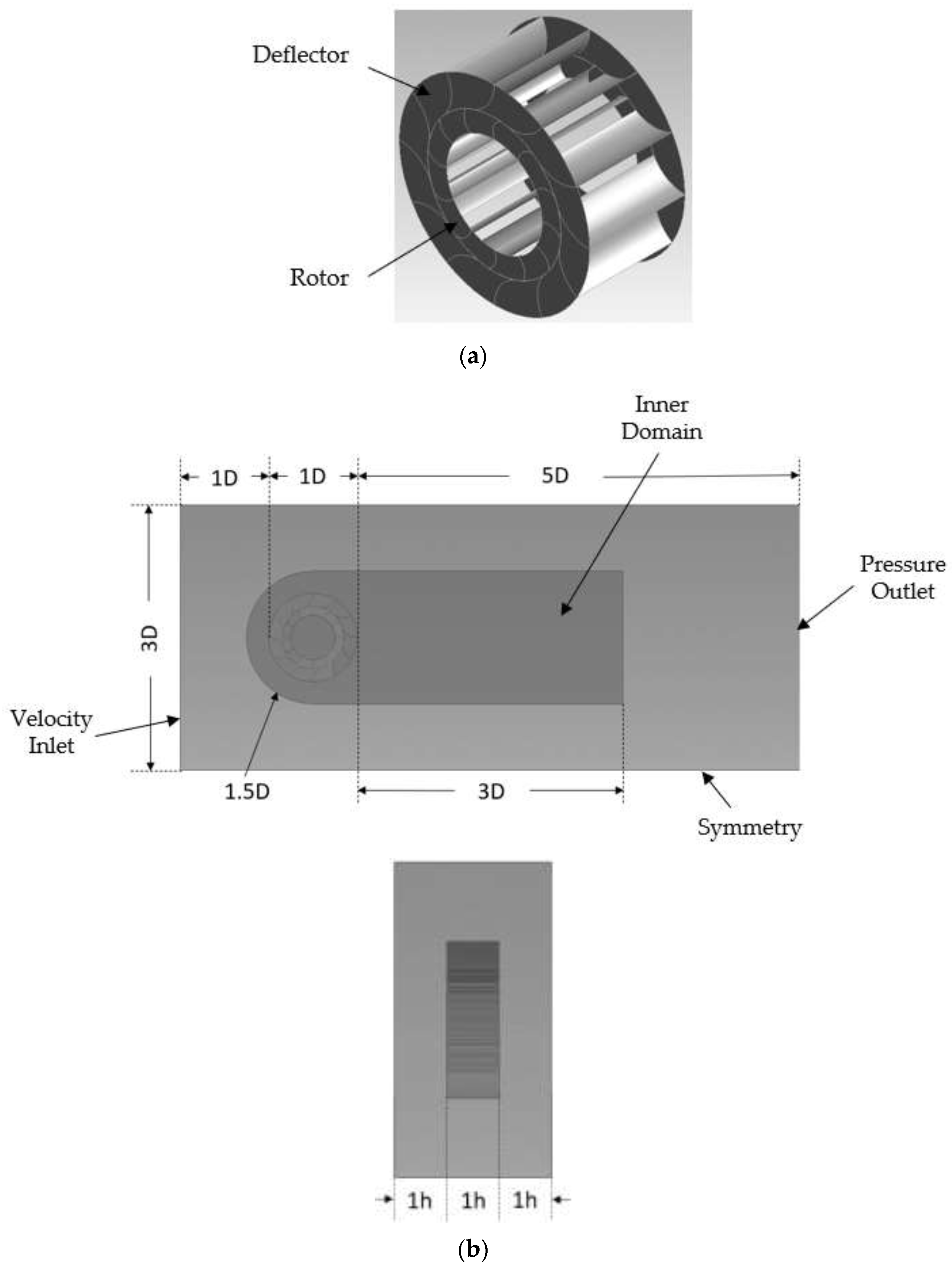
2.1. Geometry of the Multibladed VAWT and the Flow Domain

The design of the multibladed VAWT is based on [13] and comprises 12 rotor blades and 12 deflector blades, as shown in Figure 1a. The diameter of the rotor is 1.4 m while that of the deflector (D) is 2 m. The height of the VAWT (h) is 1 m. Figure 1b depicts the geometry of the flow domain. It can be seen that the flow domain is composed of two regions i.e., the inner region and the outer region. These regions have been created to control the mesh density and quality in the near-VAWT and far-VAWT regions, in accordance with the recommendations in the published literature [12,14]. The dimensions of the flow domain are such that the gap between the VAWT and the upstream boundary is kept constant at 1 D, while the downstream gap is 5 D. Similarly, in the spanwise direction, the gap between the domain and the VAWTs is 1 h. These dimensions of the flow domain have been prescribed based on published numerical studies on multibladed VAWT [12,14].

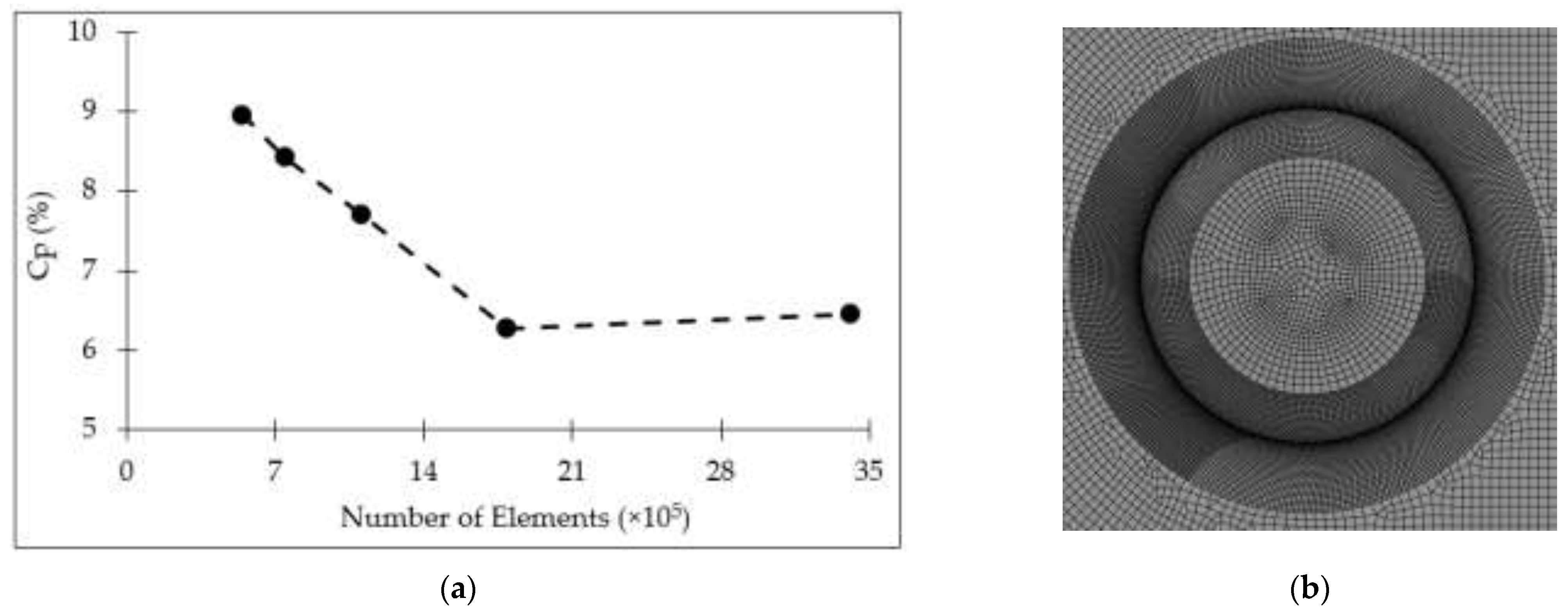
2.2. Meshing of the Flow Domain

Meshing of the flow domain was carried out in such a way that the mesh density was the finest (highest) in the flow channels between the rotor and deflector blades, while also ensuring that the mesh elements were structured, preferably quadrilateral, to minimize numerical errors. The mesh density in the core region of the VAWTs and the inner region of the flow domain was kept moderate, while it was coarsest in the outer region. For the purpose of the mesh independence study, five different element sizes were considered, as summarized in Table 1.
Figure 2a depicts the results of mesh independence testing of the multibladed VAWT. It can be seen that as the element size decreases (increasing the number of mesh elements), the numerically predicted power coefficient (Cp) of the VAWT decreases till mesh #4 (comprising 11.01 × 10⁵ elements). Further decreasing the mesh size had an insignificant effect on the accuracy of the results and thus, mesh #4 was chosen to conduct the transient aerodynamic performance characterization of the VAWT in the present study. Figure 2b depicts mesh #4 in the vicinity of the multibladed VAWT.

2.3. Boundary Conditions and Turbulence Modeling

Numerical investigations were carried out at 8 m/s wind speed, which is the average wind speed in Scotland. Thus, the upstream boundary of the flow domain was modeled as the inlet air velocity. The side walls of the flow domain were modeled symmetrically to mimic zero-shear slip walls, while the downstream boundary was modeled as a pressure outlet at 0 Pa,g to mimic the far-field.
The mass conservation equation solved within the flow domain is:
x i u i = 0
where ui is the flow velocity field. Momentum conservation/unsteady Reynolds-averaged Navier–Stokes (URANS) is:
ρ t u i + x j u i u j = P x i + μ x j u i x j + x j ρ u j ´ ¯ u i ´ ¯
where ρ is the density of air = 1.2 kg/m3, µ is the dynamic viscosity of air = 1.789 × 10⁻⁵ Pa.s, P is air pressure (Pa), and the term ρ u j ´ ¯ u i ´ ¯ represents the Reynolds stress, which was modeled using the two-equation shear-stress transport (SST) k-ω turbulence model, developed by Menter [18]. The peculiarity of the SST k-ω model to behave as a standard k-ω model in the near-wall regions (blades of the VAWT) with superior behavior in predicting wall shear, while behaving as a k-ε model away from the wall, makes it ideal for modeling air turbulence in the vicinity of the VAWT. The turbulent kinetic energy (k) and the turbulence dissipation rate (ω) are modeled as:
t ρ k + x i ρ k u i = x j σ k k x j + G k D k
t ρ ω + x i ρ ω u i = x j σ ω ω x j + G ω D ω + Y ω
where σ represents effective diffusivity, G represents a generation, D represents dissipation, and Y represents cross-diffusion.

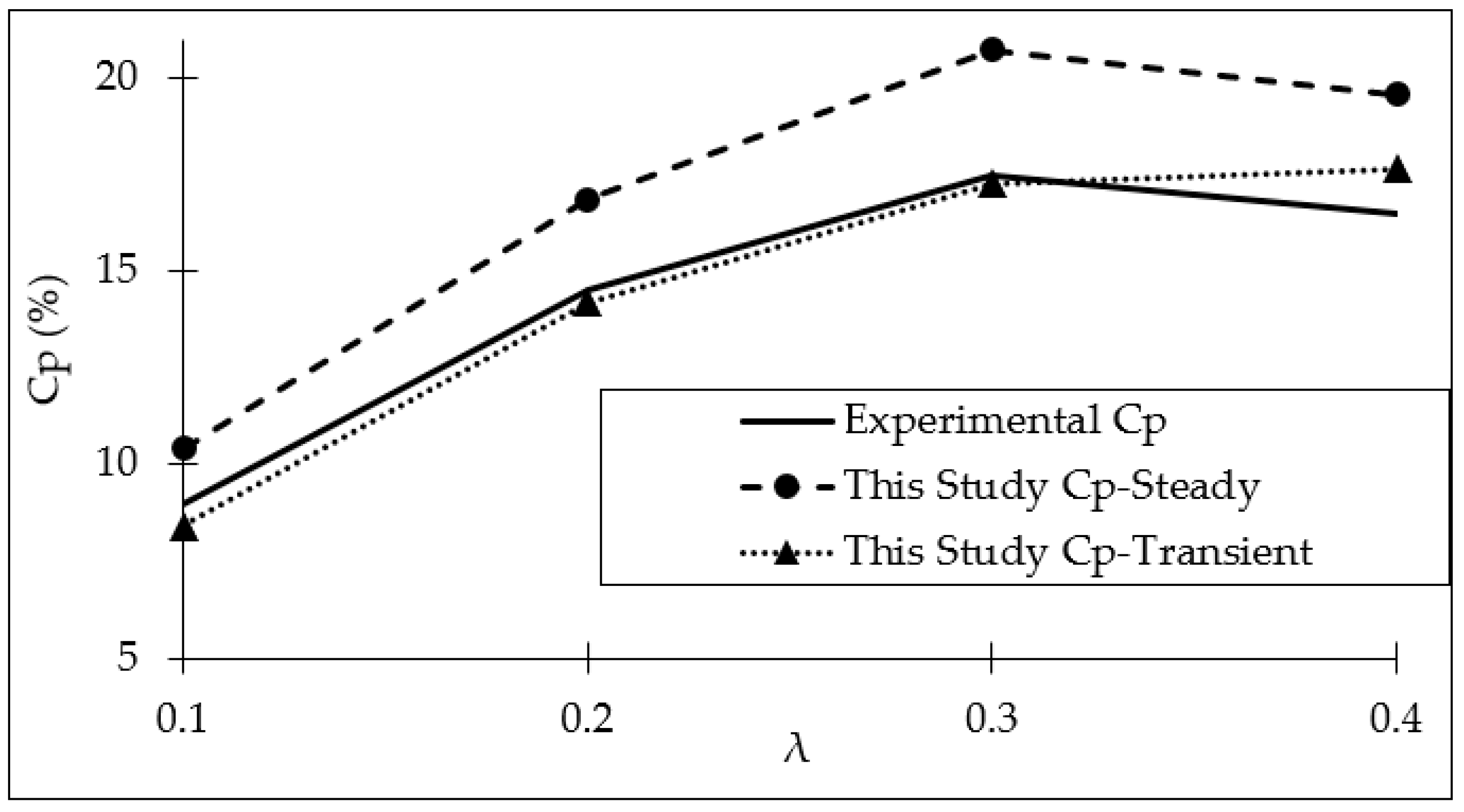
2.4. Validation of the Numerical Model

In order to validate the numerical model developed here, experimental data from Colley [13] were used. Colley used the same VAWT model and calculated the Cp of the VAWT using wind tunnel tests at various tip speed ratios (λ). The Cp and the λ were defined as:
C p = ω T 1 2 ρ A V 3   ×   100
λ = ω R V
where ω is the rotational velocity of the VAWT (rad/s), T is the torque applied by air on the VAWT (Nm), A is the projected area of the VAWT = 2 × 1 = 2 m2, V is the upstream air velocity = 8 m/s, and R is the radius of the rotor = 0.7 m. An important point to note here is that the wind tunnel used by Colley had a cross-section of 600 mm × 600 mm and thus, the incident airstream was directed towards one-half of the VAWT only. In order to validate the numerical model developed here, necessary modifications to the airflow inlet were made to ensure similarity in modeling. Figure 3 depicts the comparison between the experimental results of Colley and the numerical results of this study (both steady and revolution-averaged transient). Although the detailed results of this study are discussed in later sections, it can be clearly seen that the experimentally recorded Cp of the VAWT matches more closely to the revolution-averaged transient Cp rather than steady-state Cp. The average difference between experimental Cp and steady-state Cp is 17.3%, while between the experimental and revolution-averaged transient Cp is 4.3%, over the range considered here, i.e., λ = 0.1 to 0.4 (Colley presented results till λ = 0.4).

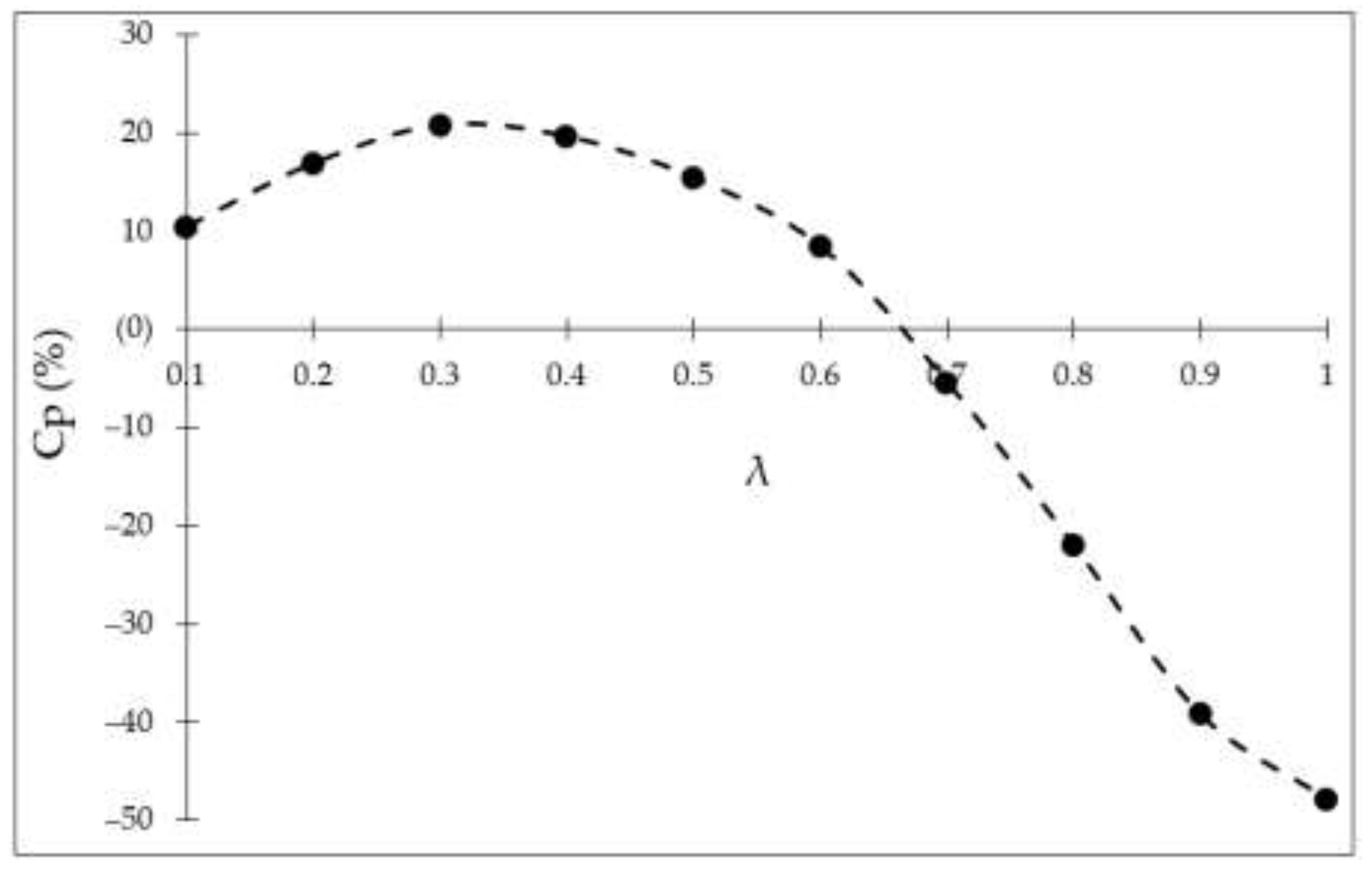
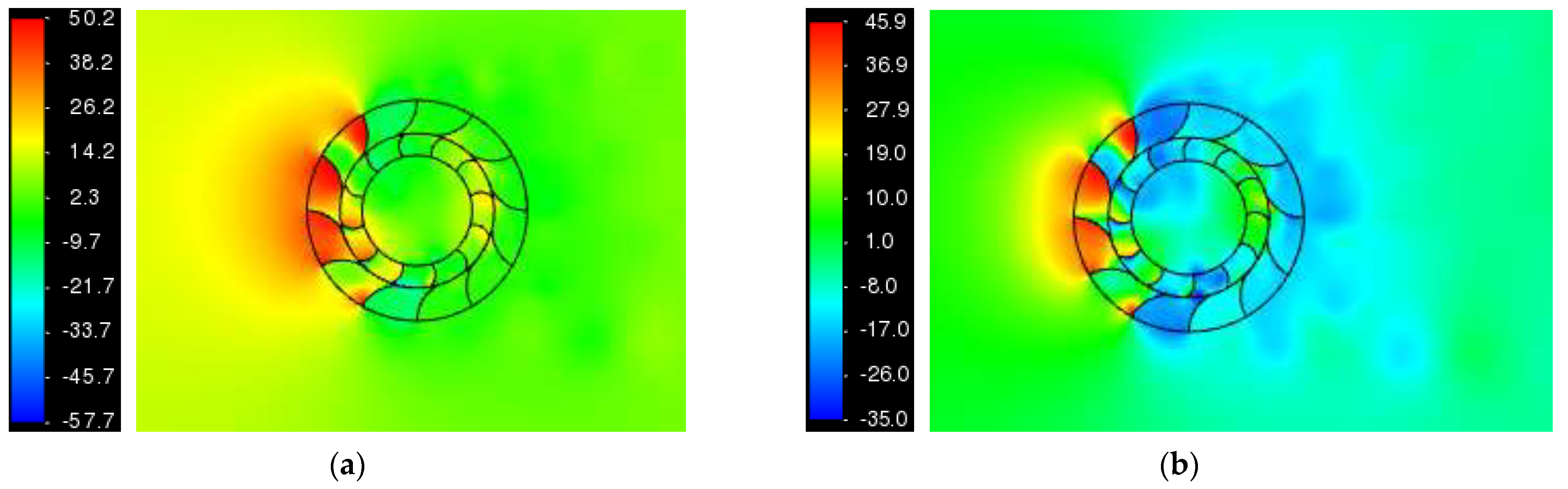
3. Steady-State Aerodynamic Characterization

Before moving on to the transient aerodynamic performance evaluation of the multibladed VAWT, it is beneficial to analyze its aerodynamic performance based on a steady-state solver, which will help highlight the advantages of transient formulation later on in this study. Multiple reference frame (MRF) modeling techniques were employed for this purpose. In the MRF technique, the rotation of blades is modeled through the application of rotational velocity components on the surface of the blades, while physically, the blades stay in the same orientation. Figure 4 depicts the variations in Cp against λ for the multibladed VAWT. It can be seen that as λ increases from 0.1 to 0.3, Cp also increases. At λ = 0.3, a peak Cp of 20% is achieved. Further increases in λ result in a decrease in Cp. At λ = 0.65, the Cp of the multibladed VAWT drops below 0. The positive Cp range of the multibladed VAWT is thus limited to λ = 0.3. From λ = 0.7, the decrease in Cp is almost linear. It should be noted that a conventional S-rotor VAWT with two blades and an aspect ratio of two, similar to the multibladed VAWT considered here, demonstrates a Cp of 6% at 8 m/s wind speed [19]. Thus, the multibladed VAWT considered here is far superior in extracting wind power than the conventional drag-based VAWTs.
Analyzing the flow fields associated with multibladed VAWT at peak and minimum Cp values, Figure 5 depicts static pressure variations in the vicinity of the VAWT at λ = 0.3 (peak Cp) in Figure 5a, and at λ = 1.0 (minimum Cp) in Figure 5b. It is clear that while operating at peak Cp, multibladed VAWT’s windward rotor blades experience significant positive air pressure. While operating at minimum Cp, the same rotor blades experience significant negative air pressure, resulting in performance degradation of the VAWT.

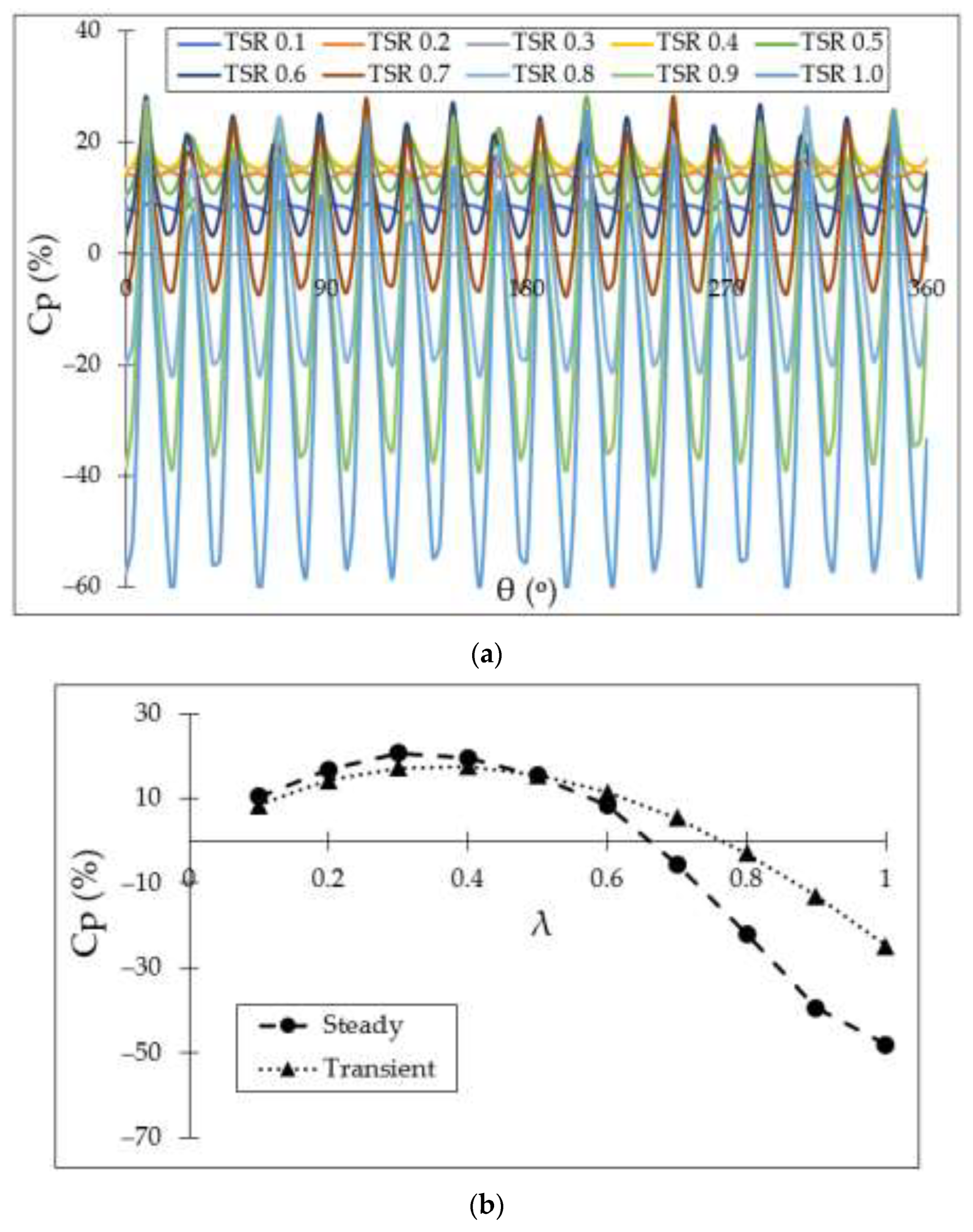
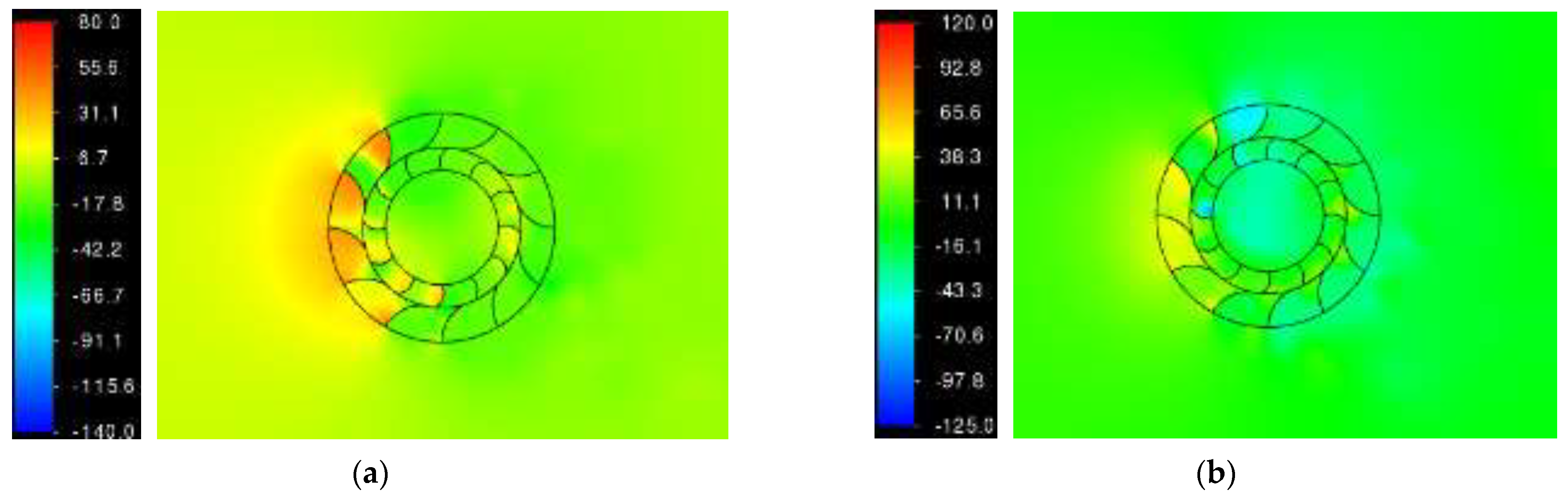
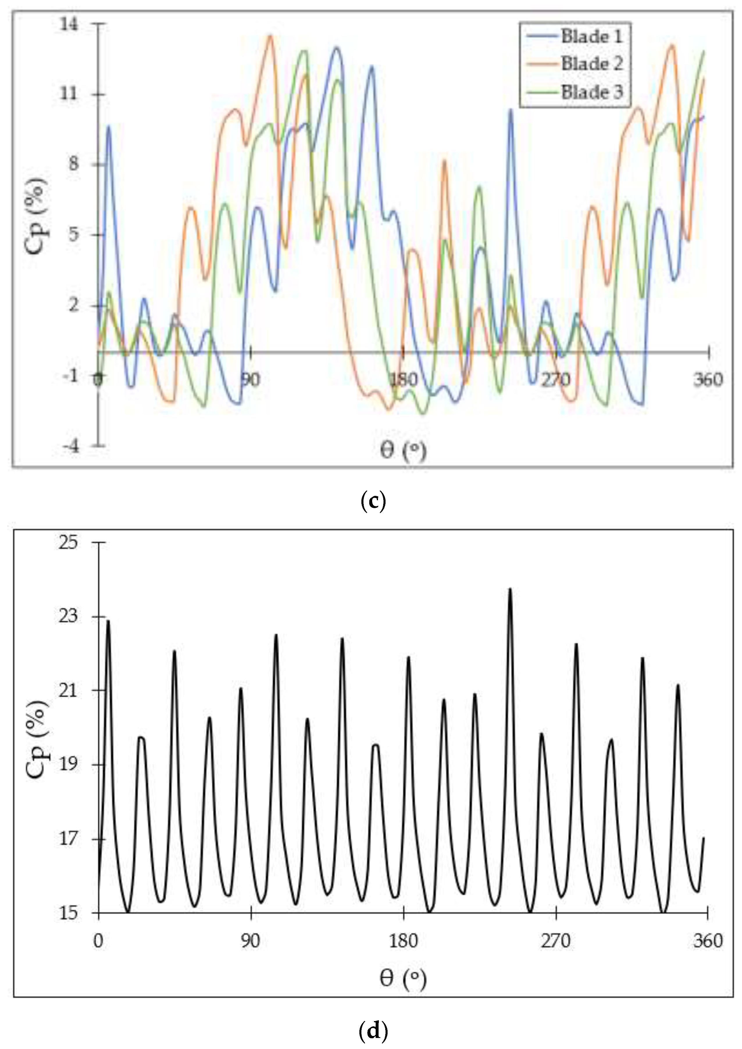
4. Transient Aerodynamic Characterization

The use of steady-state techniques, such as MRF, is computationally inexpensive, and thus, results can be obtained quickly. Transient solvers are employed where the accuracy of the numerical predictions precedes computational expense. In the present study, the sliding mesh technique was employed to investigate the transient aerodynamic performance characteristics of the multibladed VAWT. In this technique, the rotor blades rotate physically, changing orientation with respect to space and time. For accurate numerical predictions and solver stability, the choice of time step size becomes important. Several published studies by the authors [4,12,14] have established that a time step size corresponding to a 3° rotation of the blades is capable of accurately predicting the aerodynamic performance of VAWTs with reasonable accuracy when turbulence in the flow domain is modeled using two-equation models like k-ε or k-ω. Thus, in the present study, a time step size of a 3° rotation of the blades was used.
In order to analyze the transient aerodynamic performance characteristics of VAWTs, their power coefficient and static pressure fields were chosen for analysis, as in Section 3. While steady-state solvers consider a single time step, resulting in a single Cp value for the blades/rotor, transient solvers provide a range of Cp values, which in the present case is for one complete revolution of the multibladed VAWT. As mentioned earlier, the transient performance characteristics of multibladed VAWT considered here have been reported previously by the authors as well [12,14]. However, those analyses were for system-level performance. In line with the aim of the present study, the transient aerodynamic performance of individual blades is being reported for the first time here. Figure 6a depicts the variations in Cp of the multibladed VAWT at different λ values. Some general observations are that during one complete revolution of the rotor, (i) the Cp of the rotor changes quite significantly; (ii) a crest is followed by a trough and vice versa; (iii) as λ increases, variations in Cp also increase; and (iv) for λ above 0.6, the troughs are below Cp = 0. For λ = 0.1, the crest and trough Cp values are 9.9% and 7.4%, while at λ = 1, these are 25.4% and −61.1%. The reason for higher peak Cp values at higher λ is understandable, i.e., the rotor is rotating faster for a given wind speed. An interesting observation here is the shifting of Cp curves upwards as λ increases from 0.1 to 0.3. From λ = 0.4–1.0, although the peak Cp values remain the same as for λ = 0.3, the crests keep on shifting below. This clearly indicates the reasons for the decrease in Cp after λ = 0.3 i.e., the windward blades produce the same power as at λ = 0.3, and the leeward blades depict negative power.
Comparing the multibladed VAWT’s Cp from steady-state and transient solvers, it can be seen in Figure 6b that the revolution-averaged Cp of the VAWT is slightly lower than steady-state Cp till λ = 0.5. After this λ, there is a sharp drop in steady-state Cp while there is a more gradual drop in revolution-averaged transient Cp. While the steady-state Cp drops below 0% at λ = 0.65, transient Cp drops below 0% at λ = 0.75. Thus, the operational range of the multibladed VAWT predicted by the transient solver is wider. Moreover, at λ = 1.0, the revolution-averaged transient Cp is −25%, compared to −48% predicted by the steady-state solver. Figure 6c,d depict the variations in transient Cp of individual rotor blades and the resultant of the VAWT at λ = 0.3. For clearer representation, instantaneous Cps of only three rotor blades are shown. It can be seen that the aerodynamic journey of each blade is the same. The blades mostly produce positive Cp. Figure 6d indicates that the net Cp of the rotor is always positive at λ = 0.3. The reason for net positive Cp produced by the blades of multibladed VAWT is down to the large number of blades in the VAWT. This clearly indicates that increasing the number of rotor blades increases the power output of the VAWT because the blades produce more positive Cp, or they come out of their negative Cp quickly, as they are being replaced by their immediate neighboring blade.
Figure 7a,b depict local static pressure variations in the vicinity of multibladed VAWT for crests and troughs in Figure 6d. It is evident from Figure 7a that when a crest in net Cp occurs, most of the rotor blades experience positive air pressure, while in the case of troughs in net Cp, many rotor blades, especially the ones at the top and bottom of the rotor, experience significant negative air pressure. It is evident from the discussions in this study regarding pressure variations that the instantaneous position of individual rotor blades dictates their Cp contributions, while negative Cp can be mitigated to some extent using a greater number of rotor blades.

5. Conclusions

Numerical investigations on the power generating capability of a multibladed drag-based VAWT, comprising 12 rotor blades, were carried out in this study using advanced computational fluid dynamics (CFD) techniques, employing a sliding mesh solver. Comparison with the steady-state Cp and experimental data reveal that the revolution-averaged transient Cp values are closer to the experimentally recorded Cp values. The transient solver was shown to increase Cp prediction accuracy by 13%. Numerically predicted transient Cp of the multibladed VAWT provides a detailed description of the time–history of individual rotor blades during one complete revolution of the VAWT. The results obtained indicate that as λ increases beyond peak Cp, crests Cp of the VAWT remain the same; however, the trough Cp of the VAWT decreases, demonstrating that the Cp of the leeward rotor blades falls below 0%. At peak net Cp, individual blades of the rotor produce positive Cp for the majority of the rotation, while the net Cp of the rotor is always positive. This occurs because the negative Cp of an individual blade is compensated by the positive Cp of the neighboring blades. Net Cp crest flow diagnostics depict that most of the rotor blades experience positive air pressure, while net Cp trough is associated with significant negative pressure at most of the rotor blades.

Author Contributions

Conceptualization, T.A. and S.Z.I.; methodology, T.A., J.C., T.L. and D.S.; formal analysis, T.A., J.C., T.L. and D.S.; investigation, T.A., J.C. and T.L.; resources, T.A. and S.Z.I.; data curation, T.A. and D.S.; writing—original draft preparation, T.A., J.C., T.L. and D.S.; writing—review and editing, S.Z.I. and M.S.S.; supervision, T.A., S.Z.I. and M.S.S. All authors have read and agreed to the published version of the manuscript.

Funding

This research received no external funding.

Data Availability Statement

Data are contained within the article.

Conflicts of Interest

The authors declare no conflict of interest.

References

  1. Scottish Government. Energy Statistics for Scotland. 2022. Available online: https://www.gov.scot/publications/energy-statistics-for-scotland-q4-2022/#:~:text=March%202023-,Key%20Points,figure%20to%20date%2C%20overtaking%202020. (accessed on 12 November 2023).
  2. Commons, C.; Winslow, A. Clark University. 2017. Available online: https://commons.clarku.edu/cgi/viewcontent.cgi?article=1158&context=idce_masters_paperp. (accessed on 19 December 2023).
  3. Wong, K.H.; Chong, W.T.; Sukiman, N.L.; Poh, S.C.; Shiah, Y.C.; Wang, C.T. Performance enhancements on vertical axis wind turbines using flow augmentation systems: A review. Renew. Sustain. Energy Rev. 2017, 73, 904–921. [Google Scholar] [CrossRef]
  4. Gerrie, C.; Islam, S.Z.; Gerrie, S.; Turner, N.; Asim, T. 3D CFD Modelling of Performance of a Vertical Axis Turbine. Energies 2023, 16, 1144. [Google Scholar] [CrossRef]
  5. Beller, C.; Urban Wind Energy—State of the Art 2009. Technical Report. National Laboratories for Sustainable Energy. Technical University of Denmark. 2009. Available online: https://www.google.com/url?sa=t&rct=j&q=&esrc=s&source=web&cd=&ved=2ahUKEwij_Ira6YqDAxU0UkEAHZvWBUQQFnoECA0QAQ&url=https%3A%2F%2Forbit.dtu.dk%2Ffiles%2F3947129%2Fris-r-1668.pdf&usg=AOvVaw0zrECDfqtG74fmdVu84020&opi=89978449. (accessed on 6 December 2023).
  6. Balduzzi, F.; Bianchini, A.; Carnevale, E.A.; Ferrari, L.; Magnani, S. Feasibility analysis of a Darrieus vertical-axis wind turbine installation in the rooftop of a building. Appl. Energy 2012, 97, 921–929. [Google Scholar] [CrossRef]
  7. Deng, W.; Liu, L.; Guo, Y.; Li, H. Effect of helical twist angle on the aerodynamic performance and blade dynamic characteristics of floating vertical axis wind turbines. Mar. Struct. 2022, 83, 103172. [Google Scholar] [CrossRef]
  8. Elsakka, M.M.; Ingham, D.B.; Ma, L.; Pourkashanian, M. CFD analysis of the angle of attack for a vertical axis wind turbine blade. Energy Convers. Manag. 2019, 182, 154–165. [Google Scholar] [CrossRef]
  9. Subramanian, A.; Yogesh, A.; Sivanandan, H.; Giri, A.; Vasudevan, M.; Mugundhan, V.; Velamati, R.K. Effect of airfoil and solidity on performance of small-scale vertical axis wind turbine using three dimensional CFD model. Energy 2017, 133, 179–190. [Google Scholar] [CrossRef]
  10. Fatahian, H.; Mishra, M.; Jackson, F.F.; Fatahian, E. Design optimization of an innovative deflector with bleed jets to enhance the performance of dual Savonius turbines using CFD-Taguchi method. Energy Convers. Manag. 2023, 296, 117655. [Google Scholar] [CrossRef]
  11. Ushiyama, I.; Nagai, H.; Shinoda, J. Experimentally Determining the Optimum Design Configuration for Savonius Rotors. Int. J. Ser. B-Fluids Therm. Eng. 1986, 29, 4130. [Google Scholar]
  12. Asim, T.; Islam, S.Z. Effects of Damaged Rotor on Wake Dynamics of Vertical Axis Wind Turbines. Energies 2021, 14, 7060. [Google Scholar] [CrossRef]
  13. Colley, G. Design, Operation and Diagnostics of a Vertical Axis Wind Turbine. Ph.D. Thesis, University of Huddersfield, Huddersfield, UK, 2012. [Google Scholar]
  14. Asim, T.; Singh, D.; Siddiqui, M.S.; McGlinchey, D. Effect of Stator Blades on the Startup Dynamics of a Vertical Axis Wind Turbine. Energies 2022, 15, 8135. [Google Scholar] [CrossRef]
  15. Cheng, S.; Elgendi, M.; Lu, F.; Chamorro, L.P. On the Wind Turbine Wake and Forest Terrain Interaction. Energies 2021, 14, 7204. [Google Scholar] [CrossRef]
  16. Elgendi, M.; AlMallahi, M.; Abdelkhalig, A.; Selim, M.Y.E. A review of wind turbines in complex terrain. Int. J. Thermofluids 2023, 17, 100289. [Google Scholar] [CrossRef]
  17. Liu, C.; Zheng, X.; Sung, C.H. Preconditioned Multigrid Methods for Unsteady Incompressible Flows. J. Comput. Phys. 1998, 139, 35–57. [Google Scholar] [CrossRef]
  18. Menter, F.L. Zonal Two Equation k-ω Turbulence Models for Aerodynamic Flows. Am. Inst. Aeronaut. Astronaut. 1993, 2906. [Google Scholar]
  19. Mahmoud, N.H.; El-Haroun, A.A.; Wahba, E.; Nasef, M.H. An experimental study on improvement of Savonius rotor performance. Alex. Eng. J. 2012, 51, 19–25. [Google Scholar] [CrossRef]
Figure 1. (a) CAD model of the multibladed VAWT; (b) geometric details of the flow domain.
Energies 17 01900 g001
Figure 2. (a) Mesh independence test results. (b) Mesh #4 for multibladed VAWT.
Energies 17 01900 g002
Figure 3. Comparison of experimental measured and numerical predicted Cp of the multibladed VAWT.
Energies 17 01900 g003
Figure 4. Steady-state Cp variations in the multibladed VAWT.
Energies 17 01900 g004
Figure 5. Static pressure variations at (a) peak Cp and (b) minimum Cp of the multibladed VAWT.
Energies 17 01900 g005
Figure 6. Transient Cp variations for multibladed VAWT (a) at different θ; (b) comparison with steady-state Cp (c) for each blade; (d) resultant of the VAWT at λ = 0.3.
Energies 17 01900 g006aEnergies 17 01900 g006b
Figure 7. Static pressure variations in the vicinity of multibladed VAWT at (a) net Cp crest and (b) net Cp trough.
Energies 17 01900 g007
Table 1. Mesh sizing details for the flow domain.
MeshElement Size in the VAWT
(mm)
Element Size in the Inner Region
(mm)
Element Size in the Outer Region
(mm)
Total Number of Mesh Elements
(×105)
1 (coarsest)8241005.41
27211007.42
361810011.01
451510017.89
5 (finest)41210034.06
Disclaimer/Publisher’s Note: The statements, opinions and data contained in all publications are solely those of the individual author(s) and contributor(s) and not of MDPI and/or the editor(s). MDPI and/or the editor(s) disclaim responsibility for any injury to people or property resulting from any ideas, methods, instructions or products referred to in the content.

