Thermal Performance Evaluation of a Retrofitted Building with Adaptive Composite Energy-Saving Facade Systems

 , , and
Abstract
1. Introduction
Literature Review

| Authors | Year/Type of Study | Analysis of the Obtained Results in the Context of the Authors’ Research | Relationships Between Studies |
|---|---|---|---|
| De Masi R.F. et al. [33] | 2021/Experimental | It was established that the main factors influencing the ventilated facade were solar radiation and outdoor air temperature, while the influence of wind was negligible. | The study examined the parameters of only ventilated facades using recycled materials. |
| Jankovic A. et al. [34] | 2021/Theoretical and Experimental | A connection was established between the design characteristics and thermophysical processes arising in facade systems with a ventilated airgap. | The study only considered the facade’s spatial characteristics with an airgap. The effect of reflective screens was not investigated in the work. |
| Kuznetsova E.V. et al. [35] | 2021/Theoretical | It was established that the use of a ventilated facade was more efficient compared to the traditional “wet” facade, based on the example of a hotel complex construction. A comparison of the costs of required materials and installation was presented. | The study examined the structural parameters of the only traditional facade with a ventilated airgap. |
| Shahrzad S. et al. [36] | 2022/Theoretical | The CFD modeling defined that the use of ventilated facades led to efficiency in fresh air conditioning of 73% in summer and 65% in winter. At the same time, the analysis found that in winter, due to the use of an air layer, the average air temperature increased by 3 °C, while it helped to reduce the extreme temperature by 5 °C during extremely hot summers. | The study examined the parameters of only ventilated facades using recycled materials. |
| Nizovtsev, M. et al. [37,38] | 2022/Theoretical and Experimental | It was found that even with high indoor humidity of approximately 70%, the relative humidity within the insulation material remained below 50%, maintaining the panels’ excellent thermal insulation properties due to the presence of ventilated channels. | The research examined the impact of only ventilated channels on the moisture content of a building structure. The effect of reflective screens was not investigated in the work. |
| Tao Y. et al. [39,40,41] | 2022/Theoretical and Experimental | Two new models with air channels for ventilation were developed. It was established that the new models demonstrated satisfactory result convergence, with a difference of up to 9%. | As a design solution, the study examined the influence of air channels only. The effect of reflective screens was not investigated in the work. |
| Suáreza, M.J. et al. [42] | 2022/Theoretical | Various parameters were analyzed, including panel temperature, average air velocity within the cavity, and heat flow paths through the air cavity and into the room. | The study examined the use of airgaps and the influence of their only geometric parameters. The effect of reflective screens was not investigated in the work. |
| Fu Y. et al. [43] | 2023/Experimental | A new method for high-precision thermal evaluation of heat transfer in air channels in actual working environments was proposed. | The study examined the influence of sunlight exposure when the facade system contained only ventilated channels. |
| Roig O. et al. [44] | 2024/Theoretical | The influence of various characteristics of a ventilated facade was evaluated, including the exterior covering material, the relative positioning of the mass and insulation in the main wall, and the geometry of the air cavity. It was established that an air cavity of up to 10 cm led to a reduction in the average heat flux. | The study investigated the influence of ventilated airgaps only and identified the most effective geometric parameters of the airgap. |
| Domínguez-Torres C.A. et al. [45] | 2024/Theoretical | The findings indicated that the design features of the ventilated facade, considering the placement of windows, led to a reduction in heat flow by up to 32% over the annual cycle. | The investigation explored the effect of the correlation between windows and the ventilated facade. |
| Zhao X. et al. [46] | 2025/Experimental | It was established that the configuration of facades with natural ventilation, considering the optimal combination of shutters, led to significant results in terms of air volume flow at the exit of the airgap. | The research analyzed the impact of the connection between shutters and natural ventilation within facades. |
2. Methods and Materials
2.1. Geometric and Thermophysical Parameters of the Investigated External Facade Structures
2.2. Mathematical Models and Methodology for Calculating Temperature Fields in Enclosing Structures
2.3. Methodology for Evaluating the Thermal Protection of a Modernized Residential Building, Considering the Developed Energy-Efficient Facades
| Determination of the Degree Days for the Heating Period | |
|---|---|
| Thermophysical properties of materials, general information, and geometric and climatic parameters. | The indicated values for the analysis are presented in Table 1, Table 2, Table 3, Table 4, Table 5 and Table 6. |
| Thermal performance indicators: determination of the effective thermal resistance coefficient of the walls. | The effective thermal resistance of the walls was determined according to the methodology presented in Section 2.2 using the ANSYS software package, and the results are provided in Section 3.1. |
| Auxiliary indicators: overall heat transfer coefficient of the building. | |
| Specific indicators: specific thermal insulation characteristic of the building. | |
| Coefficients | The standard values are presented in Section 3.2 in Table 9. |
| Comprehensive indicators | |
| Energy loads of the building |
| Type of External Enclosure | Regulated Value, m2·°C/W | Calculated Value, m2·°C/W (Figure 3) | Calculated Value, m2·°C/W (Figure 4) | Calculated Value, m2·°C/W (Figure 5) | Calculated Value, m2·°C/W (Figure 6) | Note |
|---|---|---|---|---|---|---|
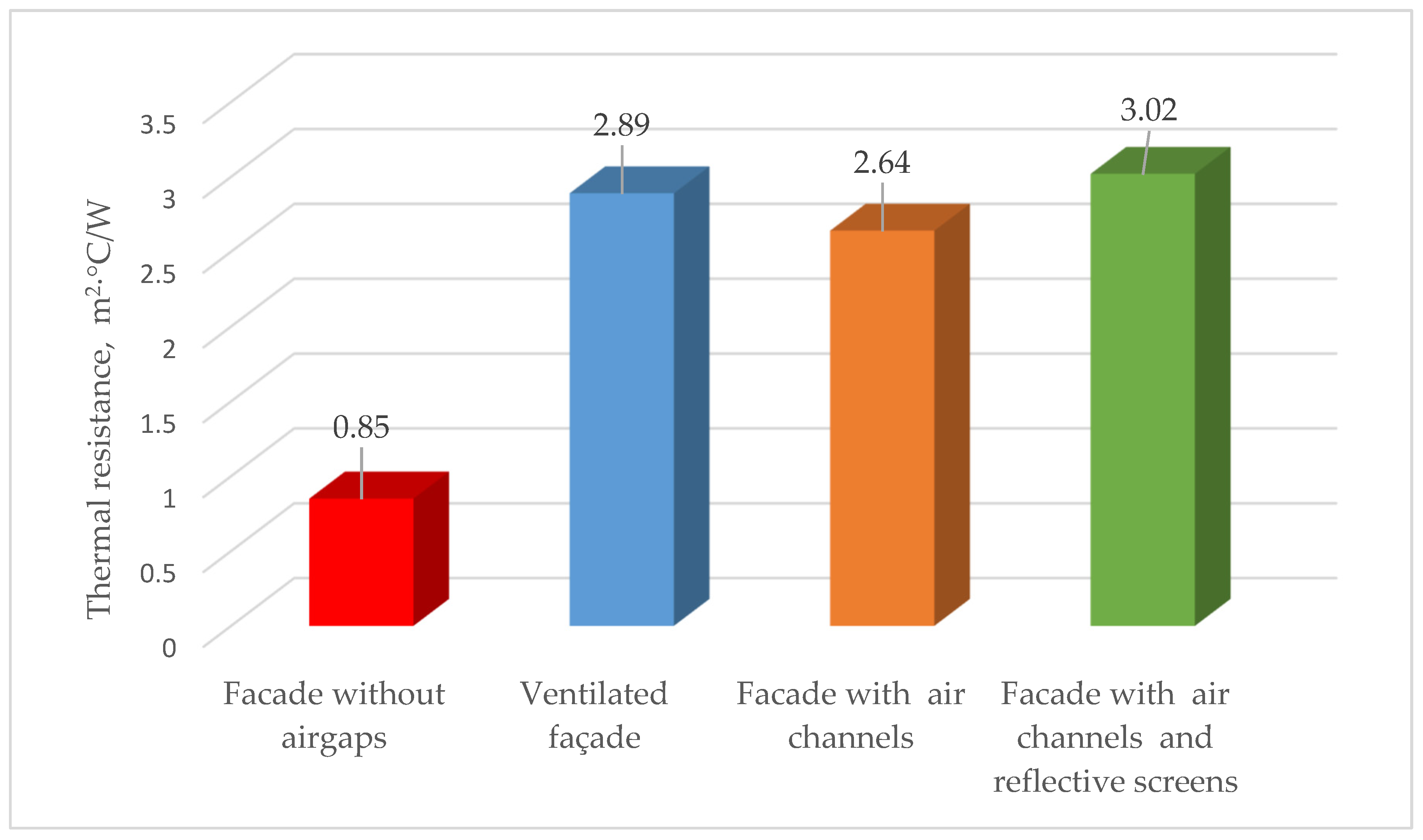
| External wall | 1.42 | 0.85 | 2.89 | 2.64 | 3.02 | Accepted to be in line with Section 3.1 |
| Windows and balcony doors | 0.32 | 0.48 | 0.48 | 0.48 | 0.48 | Accepted conditionally |
| Entrance doors and gates (separately) | 1.42 | 1.89 | 1.89 | 1.89 | 1.89 | Accepted conditionally |
| Attic ceilings | 2.4 | 2.57 | 2.57 | 2.57 | 2.57 | Accepted conditionally |
| Ceilings over technical basements or unheated cellars | 2.4 | 2.43 | 2.43 | 2.43 | 2.43 | Accepted conditionally |
3. Results and Discussions
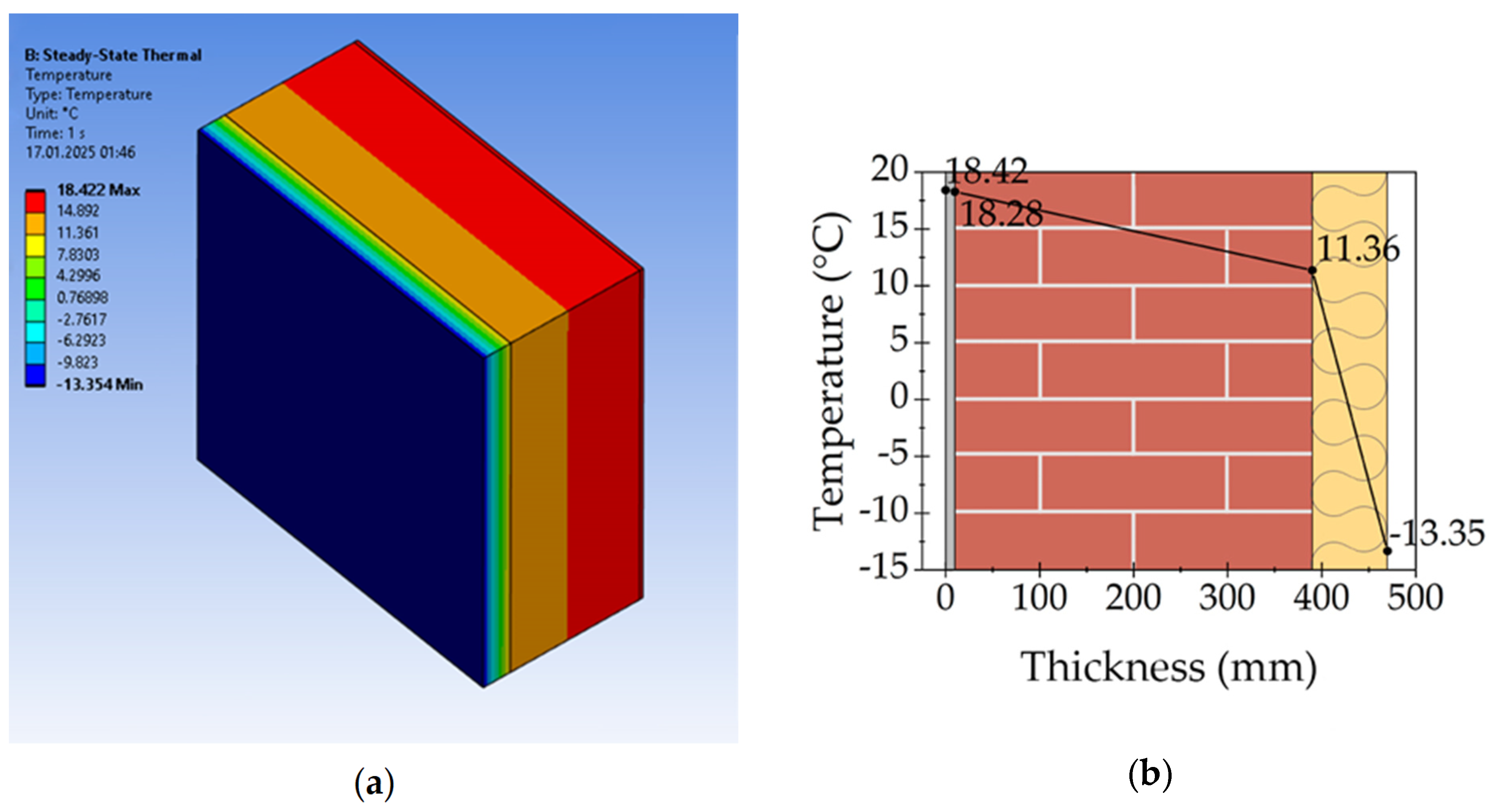
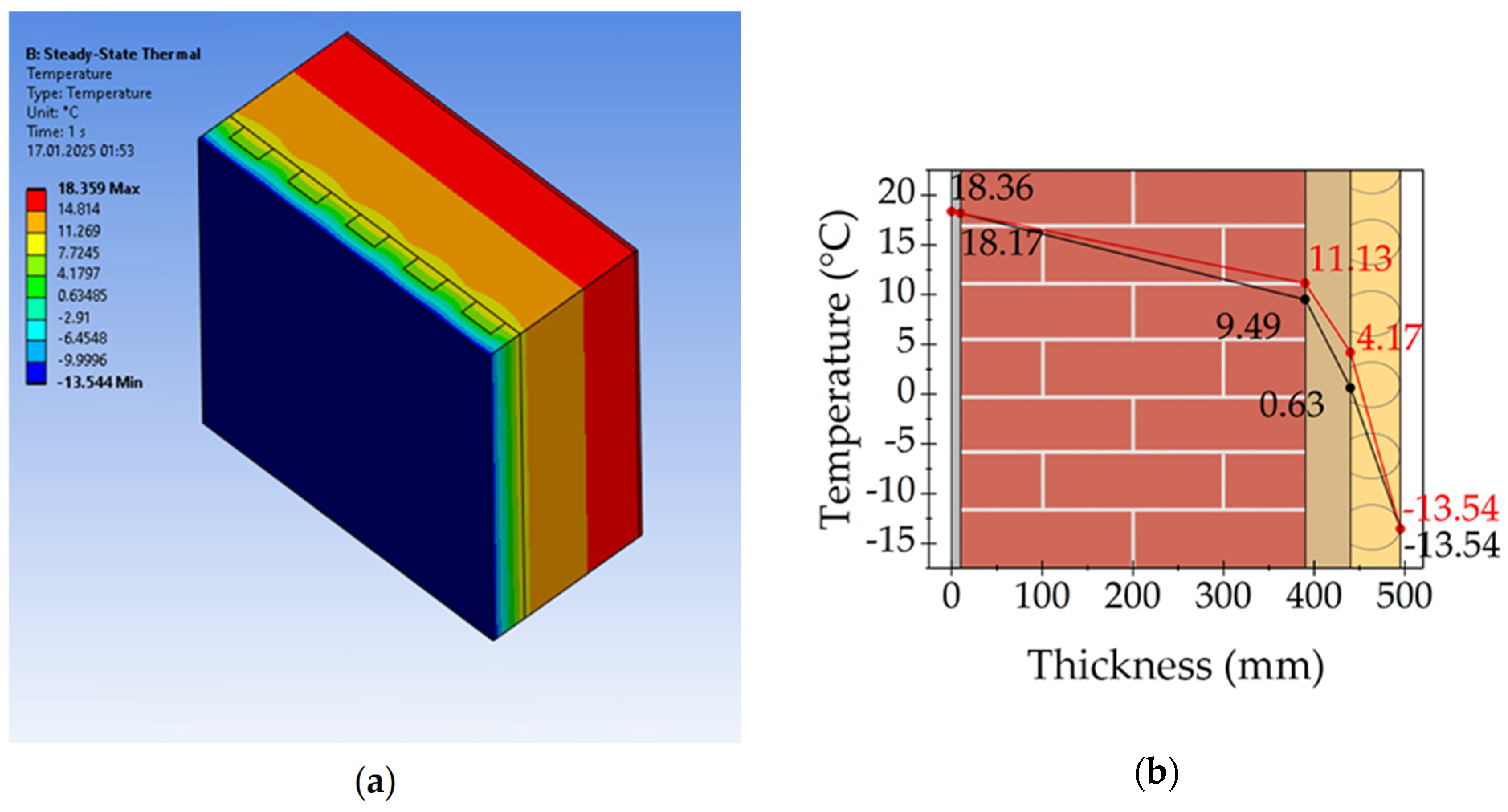
3.1. Modeling of Temperature Fields and Determination of Thermal Resistance of the Facade Structures
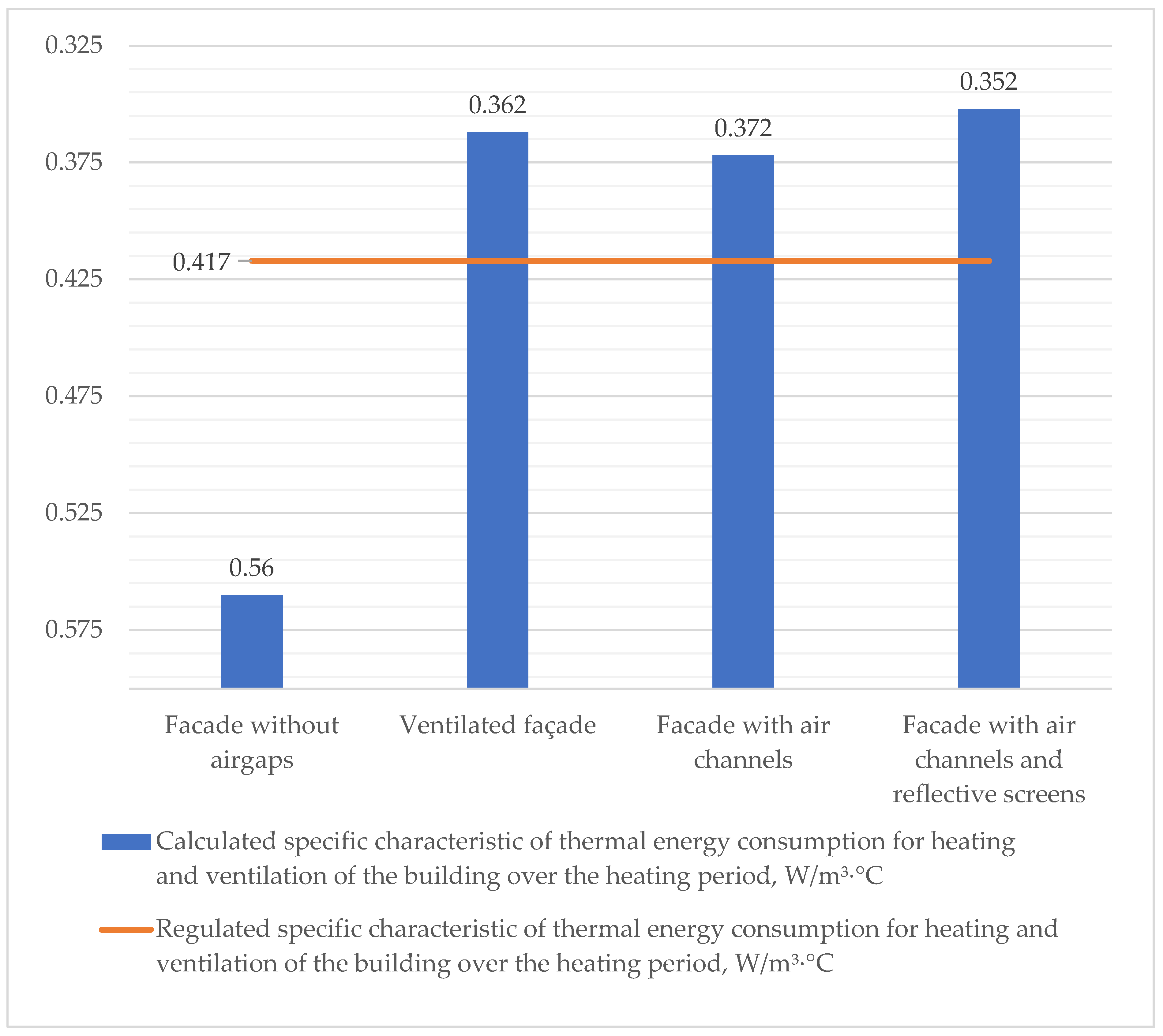
3.2. Analysis of the Thermal Protection of the Modernized Residential Building, Considering the Developed Energy-Efficient Facades
3.3. Discussions of the Study
4. Conclusions
Author Contributions
Funding
Data Availability Statement
Acknowledgments
Conflicts of Interest
Abbreviations
| Acronyms | |
| CFD | Computational fluid dynamics |
| DSF | Double-skin facade |
| H | Height difference from the air entry to the air exit in the airgap (typical value is 0.5–0.9 m) |
| External air temperature, °C | |
| Sum of local resistance coefficients (depending on the design of the ventilated facade) | |
| Threshold air temperature in the airgap, °C | |
| Conditional height at which the air temperature in the airgap differs from the threshold temperature by a factor of e, m | |
| t3 | Average external air temperature during the heating period, °C |
| Duration of the heating period, days per year | |
| t4 | Calculated internal air temperature for thermal protection, °C |
| t5 | Calculated attic temperature, °C |
| t6 | Calculated crawl space temperature, °C |
| A | Total floor area of the building, m2 |
| V | Heated volume, m3 |
| f | Faced glazing coefficient |
| A0sum | Total area of external enclosure structures of the building, m2 |
| Sum of areas (by internal measurement of all external enclosures of the heated building shell), m2 | |
| Coefficient accounting for the difference between the internal or external temperatures of the structure and those assumed in the calculation of heating period degree days (HPDDs) | |
| Area of the corresponding fragment of the building’s thermal protection shell, m2 | |
| Thermal resistance of heat transfer for the i-th fragment of the building’s thermal protection shell, m2·°C/W | |
| Air volume reduction coefficient in the building, accounting for the presence of internal enclosing structures | |
| Specific characteristic of heat intake into the building from solar radiation, W/(m3·°C) | |
| Specific ventilation characteristic of the building, W/(m3·°C) | |
References
- Nema, A.; Kumar, A.; Warudkar, V. An in-depth critical review of different carbon capture techniques: Assessing their effectiveness and role in reducing climate change emissions. Energy Convers. Manag. 2025, 323, 119244. [Google Scholar] [CrossRef]
- Manzueta, R.; Kumar, P.; Ariño, A.H.; Martín-Gómez, C. Strategies to reduce air pollution emissions from urban residential buildings. Sci. Total Environ. 2024, 951, 175809. [Google Scholar] [CrossRef]
- Shu, S.; Li, L.; Sun, A.; Cao, X. How to combine different types of prefabricated components in a building to reduce construction costs and carbon emissions? J. Build. Eng. 2024, 98, 111114. [Google Scholar] [CrossRef]
- Xian, Y.; Wang, H.; Zhang, Z.; Yang, Y.; Zhong, Y. Driving factors and reduction paths dynamic simulation optimization of carbon dioxide emissions in China’s construction industry under the perspective of dual carbon targets. Environ. Impact Assess. Rev. 2025, 112, 107789. [Google Scholar] [CrossRef]
- Yu, F.; Feng, W.; Luo, M.; You, K.; Ma, M.; Jiang, R.; Leng, J.; Sun, L. Techno-economic analysis of residential building heating strategies for cost-effective upgrades in European cities. iScience 2023, 26, 107541. [Google Scholar] [CrossRef] [PubMed]
- Zhangabay, N.; Abshenov, K.; Bakhbergen, S.; Zhakash, A.; Moldagaliyev, A. Evaluating the Effectiveness of Energy-Saving Retrofit Strategies for Residential Buildings. Int. Rev. Civ. Eng. 2022, 13, 118–126. [Google Scholar] [CrossRef]
- Available online: http://www.energimyndigheten.se/forskning-och-innovation/ (accessed on 20 January 2025).
- Shandilya, A.; Streicher, W. Performance and Cost Analysis of Retrofit Strategies Applied to a Sample Single Family House Located in New Delhi India Assisted by TRNSYS Energy Simulation Tool-A Case Study. Int. J. Eng. Technol. Res. 2017, 6, 304–312. [Google Scholar] [CrossRef]
- Cao, X.; Dai, X.; Liu, J. Building energy-consumption status worldwide and the state-of-the-art technologies for zero-energy buildings during the past decade. Energy Build. 2016, 128, 198–213. [Google Scholar] [CrossRef]
- Chen, Y.; Shen, H.; Smith, K.R.; Guan, D.; Chen, Y.; Shen, G.; Liu, J.; Cheng, H.; Zeng, E.Y.; Tao, S. Estimating household air pollution exposures and health impacts from space heating in rural China. Environ. Int. 2018, 119, 117–124. [Google Scholar] [CrossRef]
- Mora, T.D.; Pinamonti, M.; Teso, L.; Boscato, G.; Peron, F.; Romagnoni, P. Renovation of a School Building: Energy Retrofit and Seismic Upgrade in a School Building in Motta Di Livenza. Sustainability 2018, 10, 969. [Google Scholar] [CrossRef]
- Patel, M.; Seo, J.H.; Nguyen, T.T.; Kim, J. Active energy-controlling windows incorporating transparent photovoltaics and an integrated transparent heater. Cell Rep. Phys. Sci. 2021, 2, 100591. [Google Scholar] [CrossRef]
- Zhou, N.; Khanna, N.; Feng, W.; Ke, J.; Levine, M. Scenarios of energy efficiency and CO2 emissions reduction potential in the buildings sector in China to year 2050. Nat. Energy 2018, 3, 978–984. [Google Scholar] [CrossRef]
- Sadineni, S.B.; Madala, S.; Boehm, R.F. Passive building energy savings: A review of building envelope components. Renew. Sustain. Energy Rev. 2011, 15, 3617–3631. [Google Scholar] [CrossRef]
- Kudabayev, R.; Mizamov, N.; Zhangabay, N.; Suleimenov, U.; Kostikov, A.; Vorontsova, A.; Buganova, S.; Umbitaliyev, A.; Kalshabekova, E.; Aldiyarov, Z. Construction of a model for an enclosing structure with a heat-accumulating material with phase transition taking into account the process of solar energy accumulation. East. Eur. J. Enterp. Technol. 2022, 6, 26–37. [Google Scholar] [CrossRef]
- Matic, D.; Calzada, J.R.; Eric, M.; Babin, M. Economically feasible energy refurbishment of prefabricated building in Belgrade, Serbia. Energy Build. 2015, 98, 74–81. [Google Scholar] [CrossRef]
- Michalak, P. Selected Aspects of Indoor Climate in a Passive Office Building with a Thermally Activated Building System: A Case Study from Poland. Energies 2021, 14, 860. [Google Scholar] [CrossRef]
- Rinquet, L.; Schwab, S. eREN Energetic refurbishment–a global approach for the building envelope. Energy Procedia 2017, 122, 109–114. [Google Scholar] [CrossRef]
- Nik, V.M.; Mata, E.; Kalagasidis, A.S.; Scartezzini, J.L. Effective and robust energy retrofitting measures for future climatic conditions—Reduced heating demand of Swedish households. Energy Build. 2016, 121, 176–187. [Google Scholar] [CrossRef]
- Available online: https://zhkh.kz/ (accessed on 20 January 2025).
- Available online: https://www.primeminister.kz/ru/news/reviews/pyat-napravleniy-novoy-zhilishchnoy-programmy-itogi-pilotnogo-proekta-po-medstrahovaniyu-i-ceny-na-produkty-o-chem-govorili-na-ocherednom-zasedanii-pravitelstva (accessed on 20 January 2025).
- Chen, X.; Xu, Z.; Qiu, Y.; Hu, H.; Wang, X. China’s newest design of apartment buildings with modernized façade: A comparative evaluation of its energy performance in five major climate zones. Sustain. Cities Soc. 2024, 117, 105954. [Google Scholar] [CrossRef]
- Cetiner, I.; Edis, E. Assessing the effect of facade variations on post-construction period environmental sustainability of residential buildings. Sustain. Cities Soc. 2013, 6, 68–76. [Google Scholar] [CrossRef]
- Paiho, S.; Seppä, I.; Jimenez, C. An energetic analysis of a multifunctional façade system for energy efficient retrofitting of residential buildings in cold climates of Finland and Russia. Sustain. Cities Soc. 2015, 15, 75–85. [Google Scholar] [CrossRef]
- Park, H.; Su-Hwan, Y.; Jeong, H.; Kim, S.; Chang, S.J. Optimizing energy efficiency and Sustainable utilization of National Heritage through the remodeling of closed school buildings. Energy Build. 2025, 328, 115168. [Google Scholar] [CrossRef]
- Park, H.; Park, J.; Kim, S.; Chang, S.J. Energy retrofit technology for modern and contemporary educational historical buildings considering preservation and utilization aspects. Energy Rep. 2024, 11, 3995–4007. [Google Scholar] [CrossRef]
- Aloshan, M.; Aldali, K. Empirical study of facade retrofits for optimizing energy efficiency and cooling in school buildings in Saudi Arabia. Energy Rep. 2024, 12, 4105–4128. [Google Scholar] [CrossRef]
- Kyritsi, E.; Katsaprakakis, D.; Dakanali, E.; Yiannnakoudakis, Y.; Zidianakis, G.; Michael, A.; Michopoulos, A. Energy renovation of two historical buildings in Mediterranean area. J. Cult. Herit. 2025, 71, 106–113. [Google Scholar] [CrossRef]
- Woroniak, G.; Piotrowska-Woroniak, J. Effects of pollution reduction and energy consumption reduction in small churches in Drohiczyn community. Energy Build. 2014, 72, 51–61. [Google Scholar] [CrossRef]
- Zhangabay, N.; Zhangabay, A.; Utelbayeva, A.; Tursunkululy, T.; Sultanov, M.; Kolesnikov, A. Energy-Efficient Outdoor Fencing with Air Layers: A Review of the Effect of Solar Radiation on the Exterior Fencing of Buildings Made of Composite Material. J. Compos. Sci. 2025, 9, 9. [Google Scholar] [CrossRef]
- Pelletier, K.; Wood, C.; Calautit, J.; Wu, Y. The viability of double-skin façade systems in the 21st century: A systematic review and meta-analysis of the nexus of factors affecting ventilation and thermal performance, and building integration. Build. Environ. 2023, 228, 109870. [Google Scholar] [CrossRef]
- Zhangabay, N.; Tagybayev, A.; Baidilla, I.; Sapargaliyeva, B.; Shakeshev, B.; Baibolov, L.; Duissenbekov, B.; Utelbayeva, A.; Kolesnikov, A.; Izbassar, A.; et al. Multilayer External Enclosing Wall Structures with Air Gaps or Channels. J. Compos. Sci. 2023, 7, 195. [Google Scholar] [CrossRef]
- De Masi, R.F.; Ruggiero, S.; Vanoli, G.P. Hygro-thermal performance of an opaque ventilated façade with recycled materials during wintertime. Energy Build. 2021, 245, 110994. [Google Scholar] [CrossRef]
- Jankovic, A.; Goia, F. Impact of double skin facade constructional features on heat transfer and fluid dynamic behaviour. Build. Environ. 2021, 196, 107796. [Google Scholar] [CrossRef]
- Kuznetsova, E.V.; Khusainova, K.A. Choice of energy-saving façade systems in the construction hotels. Theory Pract. Mod. Sci. 2021, 4, 103–107. [Google Scholar] [CrossRef]
- Shahrzad, S.; Umberto, B. Parametric optimization of multifunctional integrated climate-responsive opaque and ventilated façades using CFD simulations. Appl. Therm. Eng. 2022, 204, 117923. [Google Scholar] [CrossRef]
- Nizovtsev, M.I.; Letushko, V.N.; Borodulin, V.Y.; Sterlyagov, A.N. Experimental studies of the thermo and humidity state of a new building facade insulation system based on panels with ventilated channels. Energy Build. 2020, 206, 109607. [Google Scholar] [CrossRef]
- Borodulin, V.Y.; Nizovtsev, M.I. Modeling heat and moisture transfer of building facades thermally insulated by the panels with ventilated channels. J. Build. Eng. 2021, 40, 102391. [Google Scholar] [CrossRef]
- Tao, Y.; Yan, Y.; Fang, X.; Zhang, H.; Tu, J.; Shi, L. Solar-assisted naturally ventilated double skin façade for buildings: Room impacts and indoor air quality. Build. Environ. 2022, 216, 109002. [Google Scholar] [CrossRef]
- Tao, Y.; Fang, X.; Chew, M.; Zhang, L.; Tu, J.; Shi, L. Predicting airflow in naturally ventilated double-skin facades: Theoretical analysis and modelling. Renew. Energy 2021, 179, 1940–1954. [Google Scholar] [CrossRef]
- Tao, Y.; Zhang, H.; Zhang, L.; Zhang, G.; Tu, J.; Shi, L. Ventilation performance of a naturally ventilated double-skin façade in buildings. Renew. Energy 2021, 167, 184–198. [Google Scholar] [CrossRef]
- Suáreza, M.J.; Sánchez, M.N.; Blanco, E.; Jiménez, M.J.; Giancola, E. A CFD Energetic study of the influence of the panel orientation in Open Joint Ventilated Façades. Energy Rep. 2022, 8, 665–674. [Google Scholar] [CrossRef]
- Fu, Y.; Xu, W.; Wang, Z.; Zhang, S.; Chen, X.; Chu, J. Experimental investigation on thermal characteristics and novel thermal estimation method of BIPV façade air channel under actual operation. J. Build. Eng. 2023, 72, 106489. [Google Scholar] [CrossRef]
- Roig, O.; Summa, S.; Pardal, C.; Isalgue, A.; Di Perna, C.; Stazi, F. Opaque ventilated façades: Energy performance for different main walls and claddings. Energy Build. 2024, 314, 114280. [Google Scholar] [CrossRef]
- Domínguez-Torres, C.A.; Suárez, R.; León-Rodríguez, A.L.; Domínguez-Delgado, A. Parametric energy optimization of a ventilated facade with windows in Mediterranean climates. Renew. Energy 2024, 227, 120398. [Google Scholar] [CrossRef]
- Zhao, X.; Song, Y.; Huang, L.; Song, Z.; Dong, Q.; Qi, J.; Shi, L. Controlling double-skin façades with inclined louvers for natural ventilation: An experimental and theoretical study. Appl. Energy 2025, 377, 124560. [Google Scholar] [CrossRef]
- Pastori, S.; Mereu, R.; Mazzucchelli, E.S.; Passoni, S.; Dotelli, G. Energy Performance Evaluation of a Ventilated Façade System through CFD Modeling and Comparison with International Standards. Energies 2021, 14, 193. [Google Scholar] [CrossRef]
- Zender–Świercz, E. Assessment of Indoor Air Parameters in Building Equipped with Decentralised Façade Ventilation Device. Energies 2021, 14, 1176. [Google Scholar] [CrossRef]
- Shao, Y.; Parks, A.; Ostertag, C.P. Lightweight concrete façade with multiple air gaps for sustainable and energy-efficient buildings in Singapore. Build. Environ. 2022, 223, 109463. [Google Scholar] [CrossRef]
- Rahiminejad, M.; Marie Pâris, A.L.; Ge, H.; Khovalyg, D. Performance of lightweight and heavyweight building walls with naturally ventilated passive and active facades. Energy Build. 2022, 256, 111751. [Google Scholar] [CrossRef]
- Rahiminejad, M.; Khovalyg, D. Numerical and experimental study of the dynamic thermal resistance of ventilated air-spaces behind passive and active façades. Build. Environ. 2022, 225, 109616. [Google Scholar] [CrossRef]
- Zhangabay, N.; Baidilla, I.; Tagybayev, A.; Suleimenov, U.; Kurganbekov, Z.; Kambarov, M.; Kolesnikov, A.; Ibraimbayeva, G.; Abshenov, K.; Volokitina, I.; et al. Thermophysical indicators of elaborated sandwich cladding constructions with heat-reflective coverings and air gaps. Case Stud. Constr. Mater. 2023, 18, e02161. [Google Scholar] [CrossRef]
- Zhangabay, N.; Tagybayev, A.; Utelbayeva, A.; Buganova, S.; Tolganbayev, A.; Tulesheva, G.; Jumabayev, A.; Kolesnikov, A.; Kambarov, M.; Imanaliyev, K.; et al. Analysis of the influence of thermal insulation material on the thermal resistance of new facade structures with horizontal air channels. Case Stud. Constr. Mater. 2023, 18, e02026. [Google Scholar] [CrossRef]
- Zhangabay, N.; Baidilla, I.; Tagybayev, A.; Sultan, B. Analysis of Thermal Resistance of Developed Energy-Saving External Enclosing Structures with Air Gaps and Horizontal Channels. Buildings 2023, 13, 356. [Google Scholar] [CrossRef]
- Zhangabay, N.; Bonopera, M.; Baidilla, I.; Utelbayeva, A.; Tursunkululy, T. Research of Heat Tolerance and Moisture Conditions of New Worked-Out Face Structures with Complete Gap Spacings. Buildings 2023, 13, 2853. [Google Scholar] [CrossRef]
- Karanafti, A.; Theodosiou, T. Summer thermal performance analysis of an Opaque ventilated Façade operating under the dynamic insulation principle. Energy Build. 2024, 312, 114193. [Google Scholar] [CrossRef]
- Barone, G.; Vardopoulos, I.; Attia, S.; Vassiliades, C. Optimizing energy-efficient building renovation: Integrating double-skin façades with solar systems in the Mediterranean landscape. Energy Rep. 2024, 12, 2933–2945. [Google Scholar] [CrossRef]
- Arauz, R.; Filipov, E.; Fascetti, A.; Clifford, D.T.; Brigham, J.C. Evaluation of a Kirigami-inspired double-skin adaptive façade for natural ventilation and solar harvesting to enhance indoor environment and energy performance. Energy Build. 2024, 324, 114927. [Google Scholar] [CrossRef]
- Fallahpour, M.; Khorshidi, I.M.; Ghasempour, F.; Danial, D.D.; Khoei, E.T.; Tamimi, M. A Multi-objective Optimization Framework For Designing A Double-Skin Façade In Hot-Arid Climate: Central Composite Design and CFD Simulation. Results Eng. 2025, 25, 104288. [Google Scholar] [CrossRef]
- ANSYS Learning—Thermal Convection in Heat Transfer. Available online: https://www.cloudkampus.com/course-details.php?course_id=250&Thermal+Convection+in+Heat+Transfer+online-training-course (accessed on 20 January 2025).
- Zhangabay, N.; Tursunkululy, N.; Utelbayeva, A.; Abdikerova, A.; Sultanov, S. A Study of Temperature and Humidity Conditions in a New Energy-Efficient Design of a Wall Structure with Air Gaps. Modelling 2025, 6, 12. [Google Scholar] [CrossRef]
- Code of Rules of the Republic of Kazakhstan 2.04-01-2017. Building Climatology: State Standards in the Field of Architecture, Urban Planning and Construction. Code of Rules of the Republic of Kazakhstan—JSC “KazNIISA”, LLP “Astana Stroy-Consulting”, 2017. Approved and Enacted on 20 December 2017. 43p. Available online: https://gos24.kz/uploads/documents/2022-12/sp-rk-2.04-01-2017-stroitelnaya-klimatologiya.pdf (accessed on 20 January 2025).
- Code of Rules of the Republic of Kazakhstan 2.04-107-2022. Building Heat Engineering: State Standards in the Field of Architecture, Urban Planning and Construction. Code of Rules of the Republic of Kazakhstan—JSC “KazNIISA”, LLP “Astana Stroy-Consulting”, 2013. Approved and Enacted on 1 July 2015. 80p. Available online: https://online.zakon.kz/Document/?doc_id=39838250 (accessed on 20 January 2025).
- Recommendations on the design of hinged facade systems with ventilated air gap for new construction and reconstruction of buildings.—Moskomarchitecture: Moscow. 2002. 159p. Available online: https://files.stroyinf.ru/Data1/9/9931/ (accessed on 20 January 2025).
- Code of Rules of the Republic of Kazakhstan 2.04-106-2012. Designing of thermal protection of buildings: State Standards in the Field of Architecture, Urban Planning and Construction. Code of Rules of the Republic of Kazakhstan—JSC “KazNIISA”, LLP “Astana Stroy-Consulting”, 2013. Approved and Enacted on 1 July 2015. 153p. Available online: https://online.zakon.kz/Document/?doc_id=35957424 (accessed on 20 January 2025).
- EN 13788 Hygrothermal Performance of Building Components and Building Elements—Internal Surface Temperature to Avoid Critical surface Humidity and Interstitial Condensation—Calculation Methods. 2001. Available online: https://cdn.standards.iteh.ai/samples/22203/9af8a82659944443b0873c17f99960e7/ISO-13788-2001.pdf (accessed on 21 January 2025).
- EN ISO 6946 Building Components and Building Elements. 2017. Available online: https://www.en-standard.eu/iso-6946-2017-building-components-and-building-elements-thermal-resistance-and-thermal-transmittance-calculation-methods/ (accessed on 21 January 2025).
- Available online: https://adilet.zan.kz/rus/docs/Z1200000541 (accessed on 21 January 2025).
- Available online: https://adilet.zan.kz/rus/docs/P1200001117 (accessed on 21 January 2025).
- Available online: https://adilet.zan.kz/rus/docs/V1500011378 (accessed on 21 January 2025).
- Zhangabay, N.; Giyasov, A.; Ibraimova, U.; Tursunkululy, T.; Kolesnikov, A. Construction and climatic certification of an area as a prerequisite for development of energy-efficient buildings and their external wall constructions. Constr. Mater. Products. 2024, 7, 1. [Google Scholar] [CrossRef]
- Zhangabay, N.; Tursunkululy, T.; Ibraimova, U.; Abdikerova, U. Energy-Efficient Adaptive Dynamic Building Facades: A Review of Their Energy Efficiency and Operating Loads. Appl. Sci. 2024, 14, 10979. [Google Scholar] [CrossRef]
- A Patent of the Republic of Kazakhstan for the Invention—Energy-Saving Wall Enclosing Structure with Air Channels. 2024. No. 36701. Available online: https://qazpatent.kz/ru (accessed on 17 January 2025).
- Blazy, I. Construction Physics. The Designer’s Handbook. Moscow. 2012. 616p. Available online: https://elima.ru/books/?id=629 (accessed on 27 January 2025).


| Authors | Year/Type of Study | Analysis of the Obtained Results in the Context of the Authors’ Research | Relationships Between Studies |
|---|---|---|---|
| Pastori S. et al. [47] | 2021/Theoretical | Based on CFD analysis, the dependence of the energy efficiency of enclosing structures on solar radiation, the advantages of natural convection in terms of potential energy savings, and the importance of designing an optimized facade geometry were established. | The advantages of natural convection have been established in terms of the potential savings of only traditional ventilated facades. |
| Zender–Świercz, E. [48] | 2021/Theoretical | The analysis and CFD modeling led to the conclusion that facade ventilation systems were a good way to improve the indoor climate as they effectively reduced air pollution. The decentralized facade ventilation system reduced the concentration of carbon dioxide to less than 1000 parts per million and maintained the indoor air temperature in the range of 19.5–22 °C. | The study performed an analysis of a decentralized device installed on the facade of a building in which the air supply and exhaust cycles were reversed due to the correct location of the dampers |
| Shao Y. et al. [49] | 2022/Theoretical | The use of only enclosed airgaps in the concrete wall structure resulted in an ecological efficiency of up to 44%, which led to a 49% reduction in energy costs. | The study only examined designs with airgaps of the enclosed type. |
| Rahiminejad, M. et al. [50,51] | 2022/Theoretical and Experimental | It was established that increasing the cavity thickness behind the outer cladding from 45 mm to 110 mm could amplify heat flow through the cavity by up to 1.5 times. Additionally, it was demonstrated that applying reflective insulation on the cavity surface could elevate the cladding surface temperature by over 30% compared to a scenario without reflective insulation. | The study has structurally similar features, such as the use of a ventilated airgap and the presence of a reflective coating. |
| Zhangabay N. et al. [52] | 2023/Experimental | It was experimentally established that the simultaneous use of both ventilated and enclosed airgaps with a reflective screen on the facade structure demonstrated effectiveness in energy conservation. | The paper analyzes another type of thermal insulation material. However, no analysis of the thermal protection of the building was carried out. |
| Zhangabay N. et al. [53,54,55] | 2023/Theoretical | It was established that the simultaneous use of ventilated and enclosed airgaps with a reflective screen in the facade structure demonstrated energy conservation efficiency of up to 15%. | This work analyzes a different category of thermal insulation material. However, the structure’s thermal protection was not evaluated. |
| Karanafti A. et al. [56] | 2024/Experimental | It was established that the use of different configurations of airgaps led to significant energy savings of up to 2.6 times, demonstrating the positive effects of using airgaps in multilayer facade structures. | The study examined adaptive solutions to prevent air penetration into the thermal insulation layer. |
| Barone G. et al. [57] | 2024/Theoretical | It was established that the incorporation of airgaps in architectural envelope structures between two layers of concrete material can reduce heating demand by up to 5.49%. | The study examined the use of airgaps between two layers of the facade structure. |
| Arauz R. et al. [58] | 2024/Theoretical | A methodology for assessing the effectiveness of using airgaps for solar energy collection, ventilation, and temperature control in different generalized scenarios of building–environment interaction was developed. The annual efficiency reached up to 25% compared to the traditional closed facade. | The study examined the effectiveness of using airgaps alone for various situations. However, the issue of using reflective screens was not investigated, which could have positively complemented the idea of energy savings. |
| Fallahpour M. et al. [59] | 2025/Theoretical | The proven optimization system could be adapted for DSF design in various climatic conditions and building types. Computer simulation of dynamics (CFD) was performed to estimate the intensity of air flow and air temperature. | It was found that the optimal design provided a maximum mass flow rate of 0.72 kg/s and an average air velocity of 0.06 m/s while minimizing the temperature difference inside and outside the room to 1.04 °C. |
| Layer Number | Description | Thickness, mm | Thermal Conductivity Coefficient, λ, W/(m·°C) | Heat Absorption Coefficient, S, W/(m2·°C) | Vapor Permeability, μ, mg/(m·h·Pa) |
|---|---|---|---|---|---|
| 1 | Cement–sand render with a density of 1800 kg/m3 | 10 | 0.76 | 9.6 | 0.09 |
| 2 | Masonry made of terracotta brick with a density of 1800 kg/m3 | 380 | 0.7 | 9.2 | 0.11 |
| 3 | Cement–sand render with a density of 1800 kg/m3 | 10 | 0.76 | 9.6 | 0.09 |
| 4 | Insulation with basalt wool panels on the “DiRock Facade” with a density of 110 kg/m3 | 80 | 0.035 | 0.3 | 0.005 |
| 5 | Airgap | 200 | - | - | - |
| 6 | Cladding layer made of ceramic granite with a density of 2800 kg/m3 | 10 | 3.49 | 25.04 | 0.008 |
| Layer Number | Description | Thickness, mm | Width, mm | Thermal Conductivity Coefficient, λ, W/(m·°C) | Heat Absorption Coefficient, S, W/(m2·°C) | Vapor Permeability, μ, mg/(m·h·Pa) | Emissivity Factor of the Heat-Reflective Screen | |
|---|---|---|---|---|---|---|---|---|
| 1 | Cement–sand render | 10 | - | 0.76 | 9.6 | 0.09 | - | |
| 2 | Masonry made of terracotta brick | 380 | - | 0.7 | 9.2 | 0.11 | - | |
| 3 | Cement–sand render | 10 | - | 0.76 | 9.6 | 0.09 | - | |
| 4 | Insulation | Basalt wool panels on the “DiRock Facade” with a density of 110 kg/m3 | 105 | - | 0.035 | 0.3 | 0.005 | 0.039 |
| 5 | Alternating vertical stripes of basalt wool panels/air | 50 | 100 | - | - | - | ||
| 6 | Airgap | 175 | - | - | - | - | - | |
| 7 | Cladding layer made of ceramic granite | 10 | - | 3.49 | 25.04 | 0.008 | ||
| Address of the Building | Shymkent, Kazakhstan |
|---|---|
| Building purpose, series | Administrative building of Shymkent |
| Number of floors, number of sections | 1, 3 |
| Year of construction | 1966 |
| Structural solution | Brick building |
| Name of Calculated Parameters | Calculated Value |
|---|---|
| Estimated external air temperature for thermal insulation planning, °C | −14.3 |
| Mean external air temperature throughout the heating season, °C | 2.1 |
| Length of the heating season, days per year | 136 |
| Heating period degree days (HPDDs), °C·days per year | 2434 |
| Projected indoor air temperature for thermal insulation design, °C | 20 |
| Predicted attic air temperature, °C | Not considered |
| Assessed crawl space temperature, °C | Not considered |
| Indicator | Standard Value | Actual Value |
|---|---|---|
| Total floor area of the building, m2 | - | 171.4 |
| Calculated area (public buildings), m2 | - | 102.8 |
| Heated volume, m3 | - | 622.3 |
| Facade glazing coefficient | ≤0.18 | 0.17 |
| Building compactness indicator | 0.9 | 0.87 |
| Total area of external enclosing structures of the building, including, m2: | - | 538.91 |
| (1) Walls (separately by construction type) | - | 140.2 |
| (2) Windows and balcony doors | - | 29.25 |
| (3) Entrance doors and gates (separately) | - | 20.0 |
| (4) Attic ceilings | - | 174.7 |
| (5) Ceilings over technical basements or unheated cellars | - | 174.7 |
| Indicator | Regulated Value of the Indicator | Calculated Design Value of the Indicator (Figure 1a) | Calculated Design Value of the Indicator (Figure 1b) | Calculated Design Value of the Indicator (Figure 1c) | Calculated Design Value of the Indicator (Figure 1d) | Note |
|---|---|---|---|---|---|---|
| Specific thermal protection characteristic of the building, kоб, W/(m3 °C) | 0.61 | 0.37 | 0.18 | 0.19 | 0.17 | Accepted to be in line with Section 2.3 |
| Specific ventilation characteristic of the building, kвент, W/(m3 °C) | - | 0.25 | 0.25 | 0.25 | 0.25 | Accepted conditionally |
| Specific characteristic of the household heat emissions of the building, kбыт, W/(m3 °C) | - | 0.09 | 0.09 | 0.09 | 0.09 | Accepted conditionally |
| Specific characteristic of the heat gains in the building from solar radiation kрад, W/(m3 °C) | - | 0.11 | 0.11 | 0.11 | 0.11 | Accepted conditionally |
| Indicator | Standard Value of the Indicator |
|---|---|
| Efficiency coefficient of heating self-regulation, ζ | 0.5 |
| Coefficient accounting for the reduction in heat consumption in residential buildings with individual heating energy metering, ξ | 0.1 |
| Efficiency coefficient of the recuperator, kэф | 0 |
| Coefficient accounting for the reduction in the use of heat gains during periods when they exceed heat losses, ν | 0.74 |
| Coefficient accounting for additional heat losses in the heating system, βh | 1.13 |
| A++ (less than −60%) | Very high |  |
| A+ (from −50% to −60%) |  | |
| A (from −40% to −50%) |  | |
| B+ (from −30% to −40%) | High (−15.6%) |  |
| B (from −15% to −30%) |  | |
| C+ (from −5% to −15%) | Normal (−12.9% and −10.8%) |  |
| C (from +5% дo −5%) |  | |
| C− (from +15% to +5%) |  | |
| D (from +15,1% to +50%) | Reduced (+34.3%) |  |
| E (more than +50%) | Low |  |
Disclaimer/Publisher’s Note: The statements, opinions and data contained in all publications are solely those of the individual author(s) and contributor(s) and not of MDPI and/or the editor(s). MDPI and/or the editor(s) disclaim responsibility for any injury to people or property resulting from any ideas, methods, instructions or products referred to in the content. |
© 2025 by the authors. Licensee MDPI, Basel, Switzerland. This article is an open access article distributed under the terms and conditions of the Creative Commons Attribution (CC BY) license (https://creativecommons.org/licenses/by/4.0/).
Share and Cite
Zhangabay, N.; Oner, A.; Rakhimov, M.; Tursunkululy, T.; Abdikerova, U. Thermal Performance Evaluation of a Retrofitted Building with Adaptive Composite Energy-Saving Facade Systems. Energies 2025, 18, 1402. https://doi.org/10.3390/en18061402
Zhangabay N, Oner A, Rakhimov M, Tursunkululy T, Abdikerova U. Thermal Performance Evaluation of a Retrofitted Building with Adaptive Composite Energy-Saving Facade Systems. Energies. 2025; 18(6):1402. https://doi.org/10.3390/en18061402
Chicago/Turabian StyleZhangabay, Nurlan, Arukhan Oner, Murat Rakhimov, Timur Tursunkululy, and Uliya Abdikerova. 2025. "Thermal Performance Evaluation of a Retrofitted Building with Adaptive Composite Energy-Saving Facade Systems" Energies 18, no. 6: 1402. https://doi.org/10.3390/en18061402
APA StyleZhangabay, N., Oner, A., Rakhimov, M., Tursunkululy, T., & Abdikerova, U. (2025). Thermal Performance Evaluation of a Retrofitted Building with Adaptive Composite Energy-Saving Facade Systems. Energies, 18(6), 1402. https://doi.org/10.3390/en18061402