
Critical Review of Direct-Drive In-Wheel Motors in Electric Vehicles


Abstract
1. Introduction
- (1)
- It systematically examines the technical requirements for IWM drive and provides a comprehensive overview of both the currently industrial-applied and under-researched types of IWMs.
- (2)
- It discusses the applicability of different IWMs based on key performance requirements, provides a technical evaluation, and offers insights into the future development directions of IWMs.
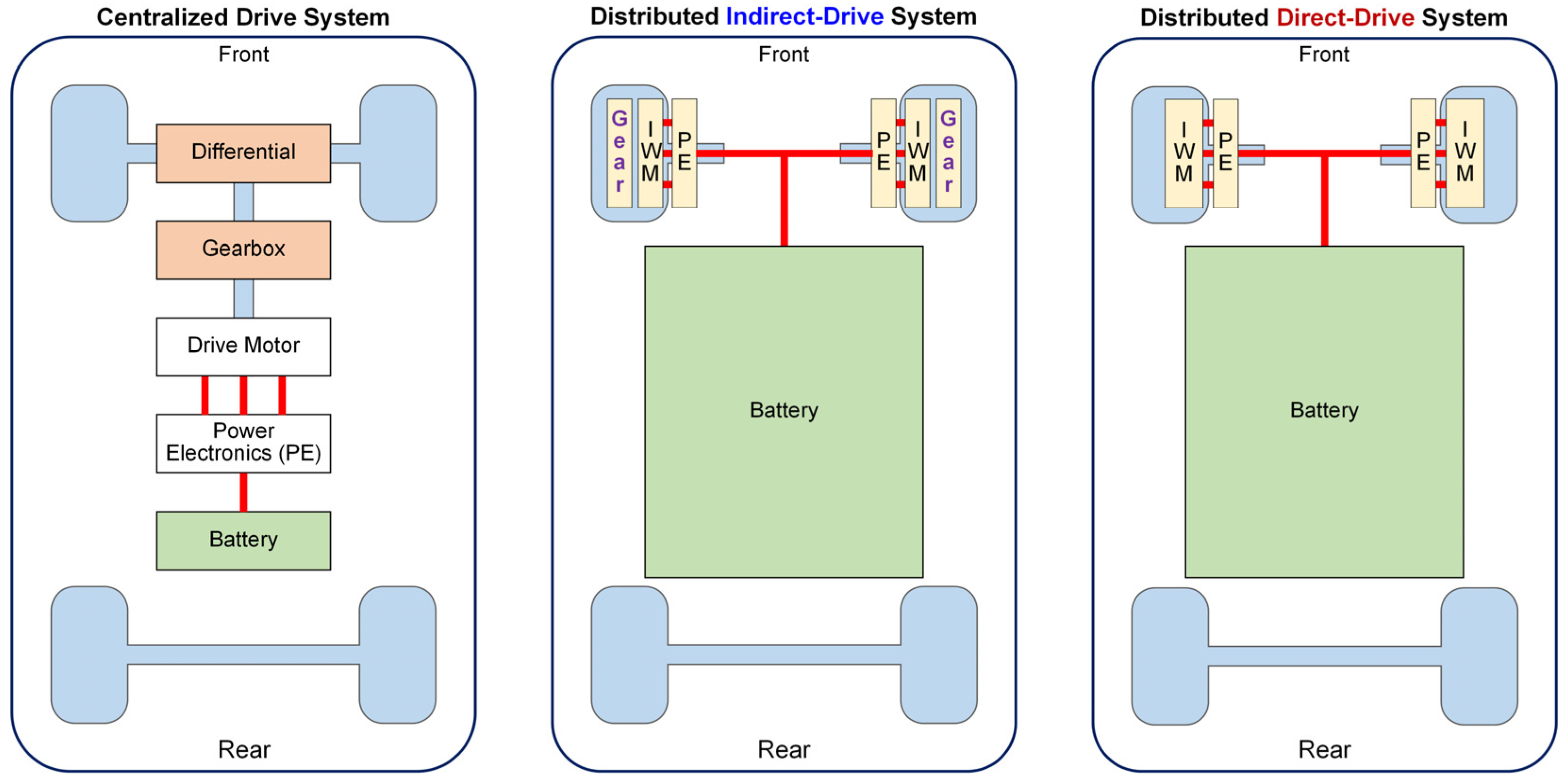
2. Main Challenges and Design Specifications of Mass-Produced Direct-Drive IWMs
2.1. Main Challenges of IWMs
- (a)
- High Torque Density
- (b)
- Low Cost
- (c)
- Robustness
- (d)
- High Efficiency
- (e)
- Ease of Production
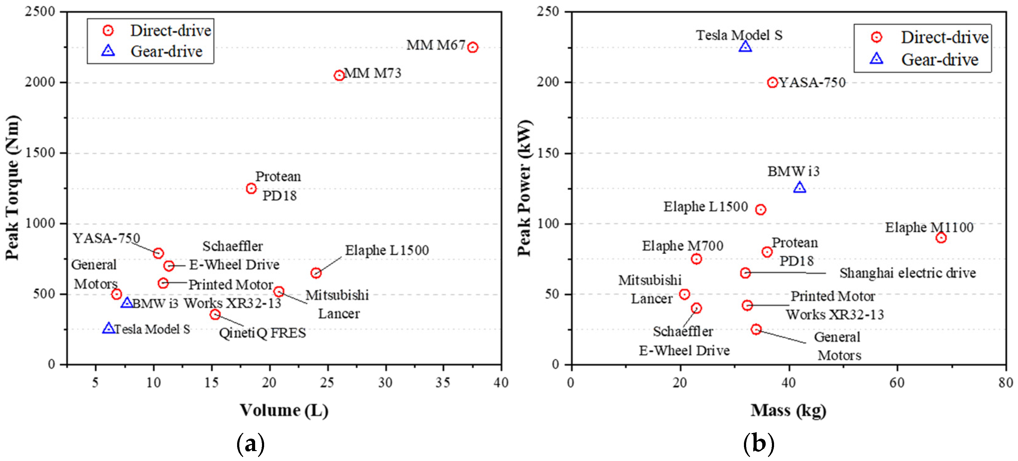
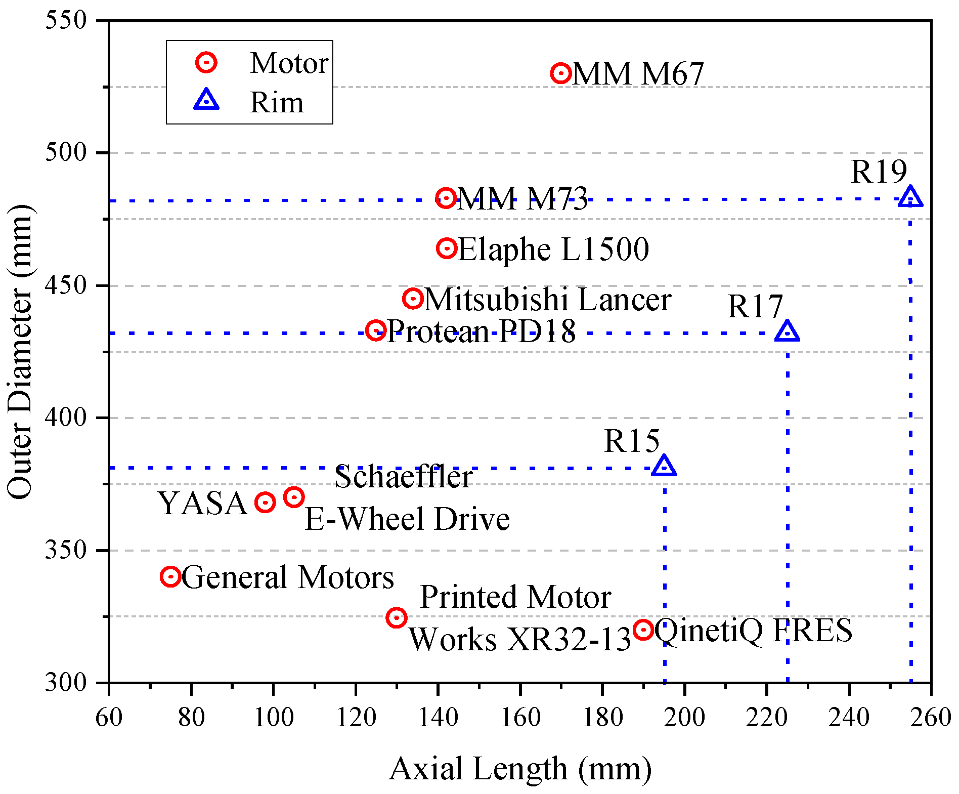
2.2. Design Specifications of IWMs
- (a)
- Dimensions
- (b)
- Power, Torque, and Speed Range
- (c)
- Weight
- (d)
- Thermal Design
3. Classifications of IWMs
3.1. Classification of IWMs Based on Airgap Flux Direction
- (a)
- Radial Flux IWMs
- (b)
- Axial Flux IWMs
- (c)
- Radial-Axial Flux IWMs
3.2. Classification of IWMs Based on Machine Topology
4. Overview and Comparative Study of Different IWM Topologies
4.1. Overview of Diverse IWM Topologies
4.1.1. Asynchronous IWMs
4.1.2. Synchronous Non-PM IWMs
4.1.3. Conventional PMSM Based IWMs
- (a)
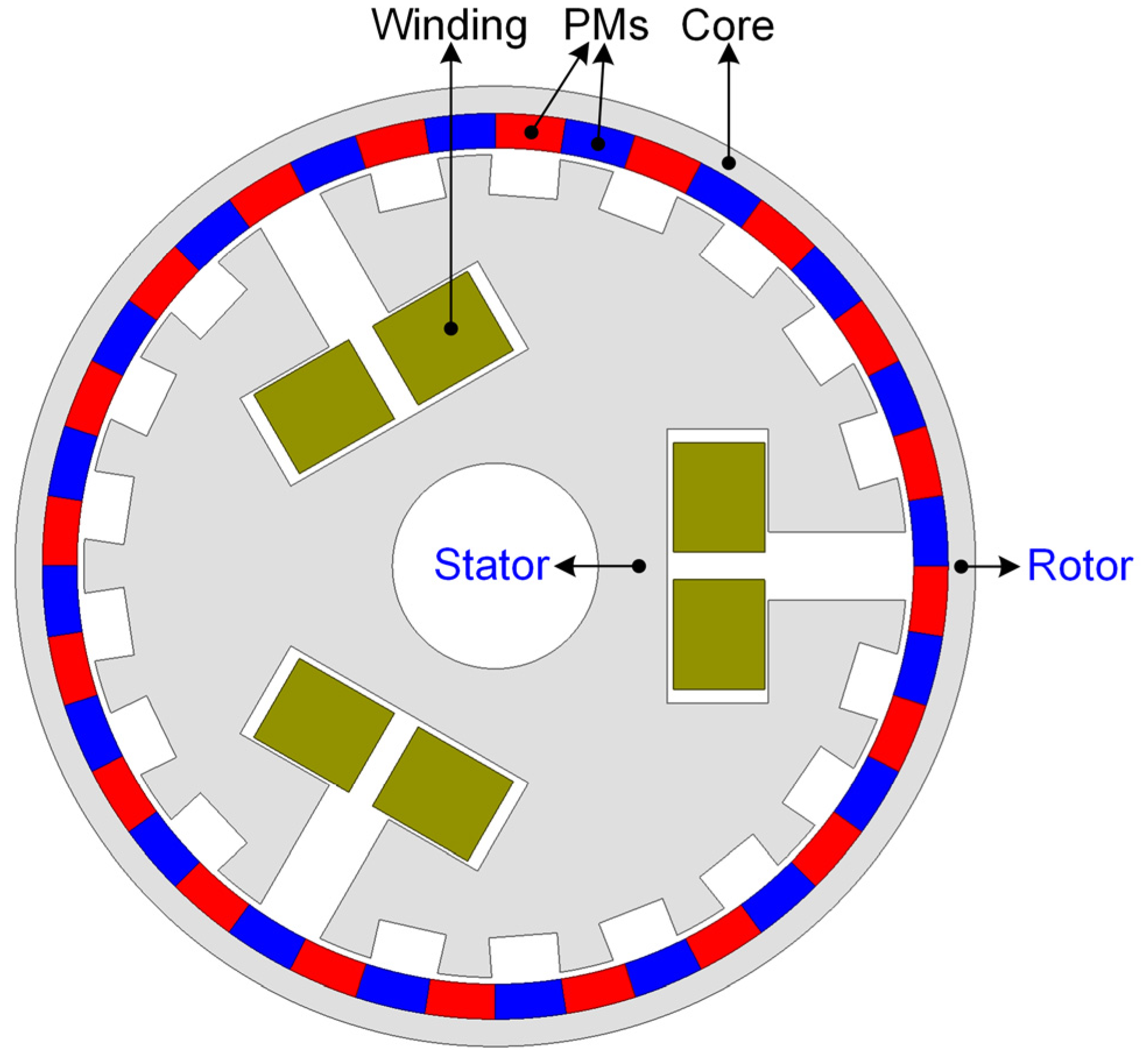
- Fractional Slot Concentrated Winding PMSM-based IWMs
- (b)
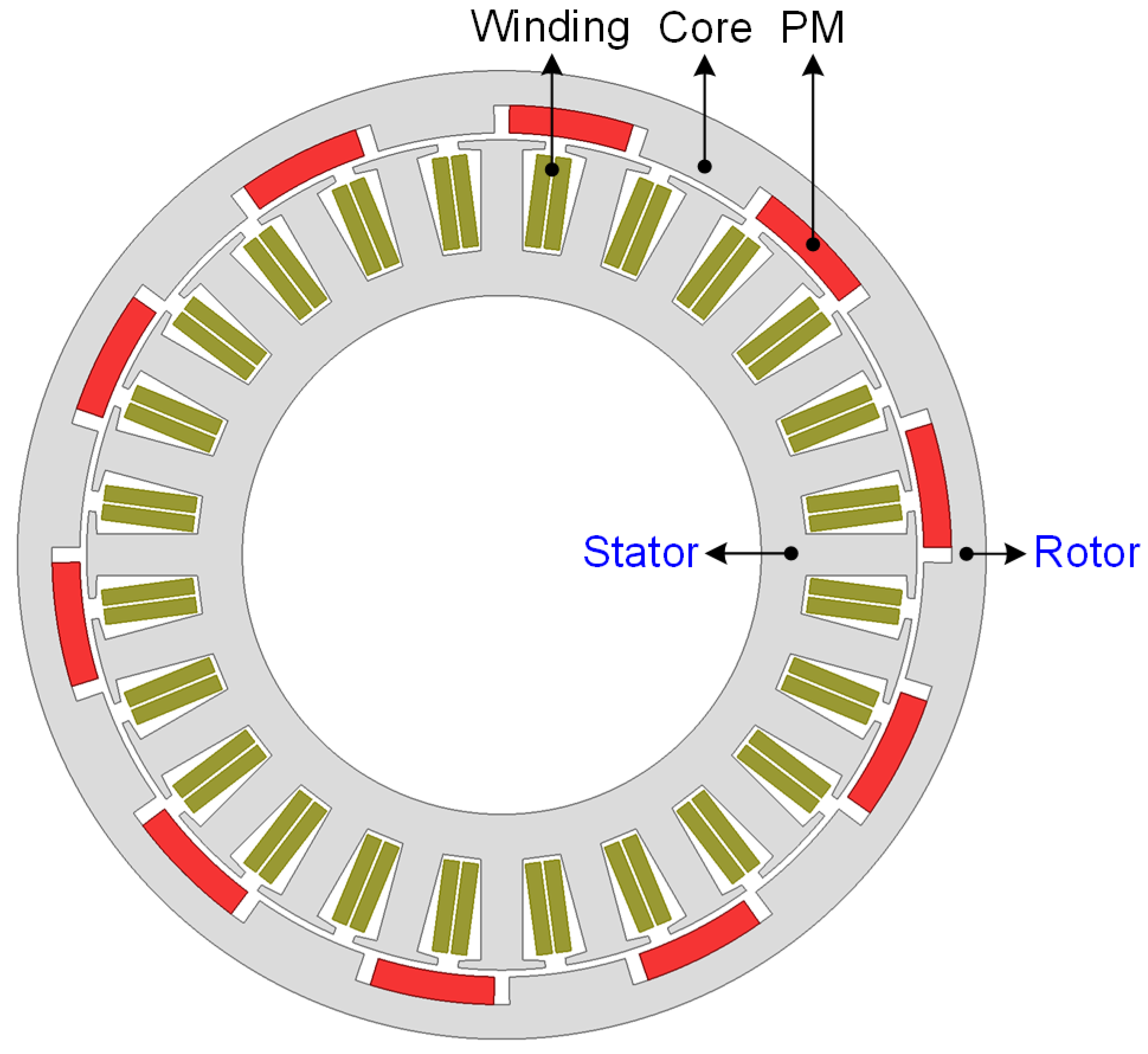
- Consequent Pole PMSM-based IWMs
4.1.4. Flux-Modulated PM IWMs
- (a)
- Magnetic Gear IWMs
- (b)
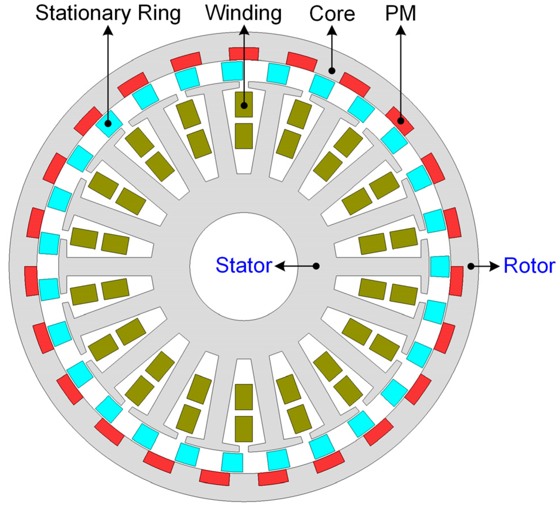
- Permanent Magnet Vernier IWMs
- (c)
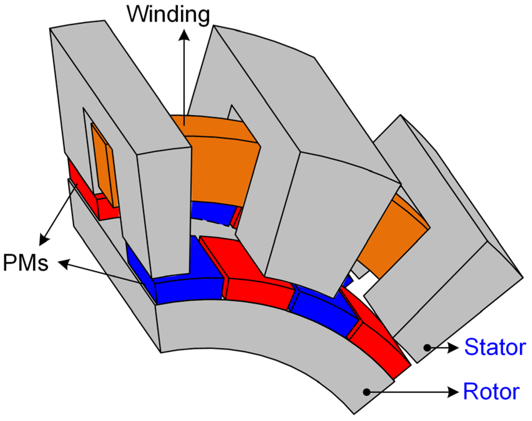
- Transverse Flux PM IWMs
- (d)
- Flux-Switching Permanent-Magnet IWMs
- (e)
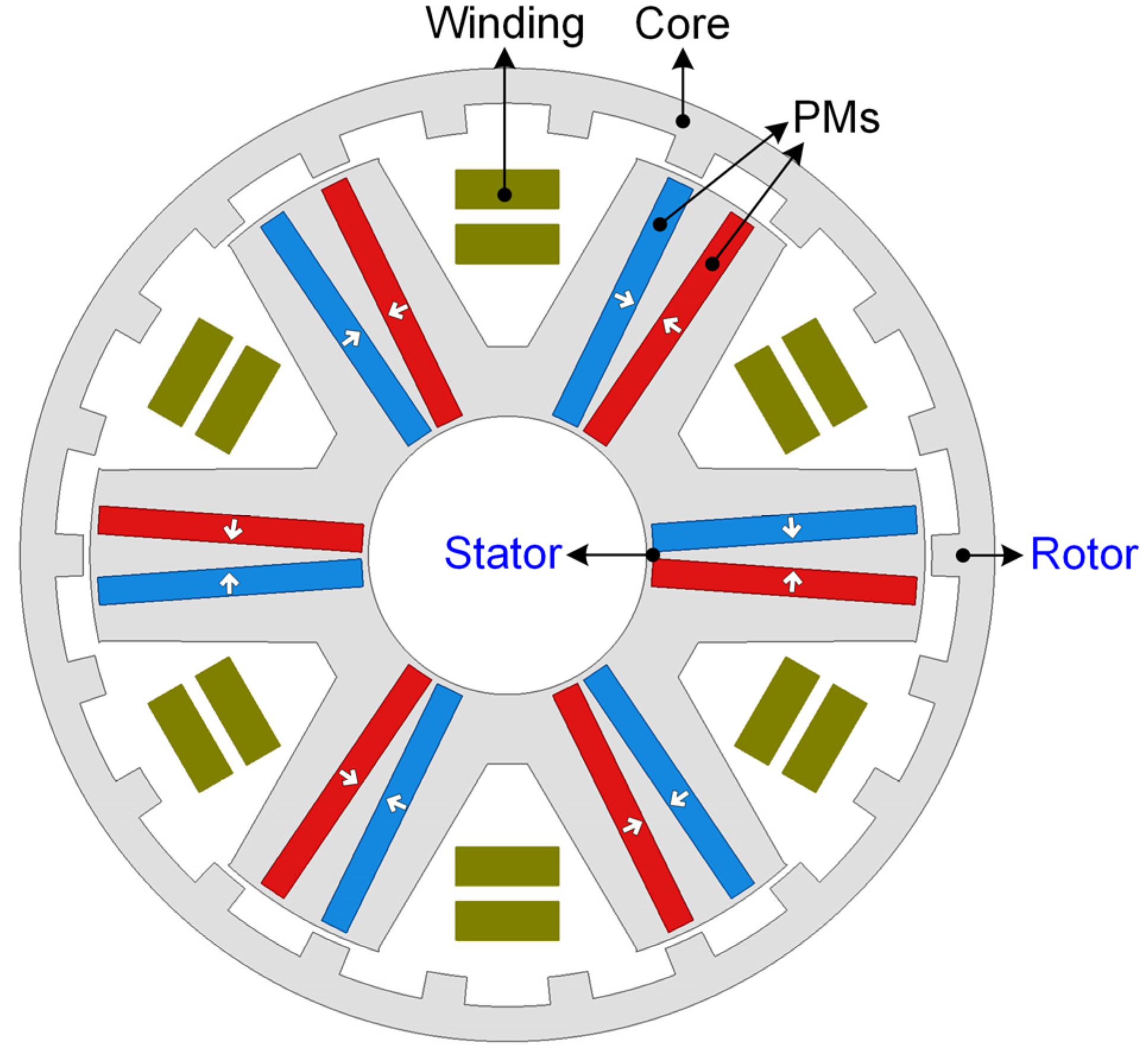
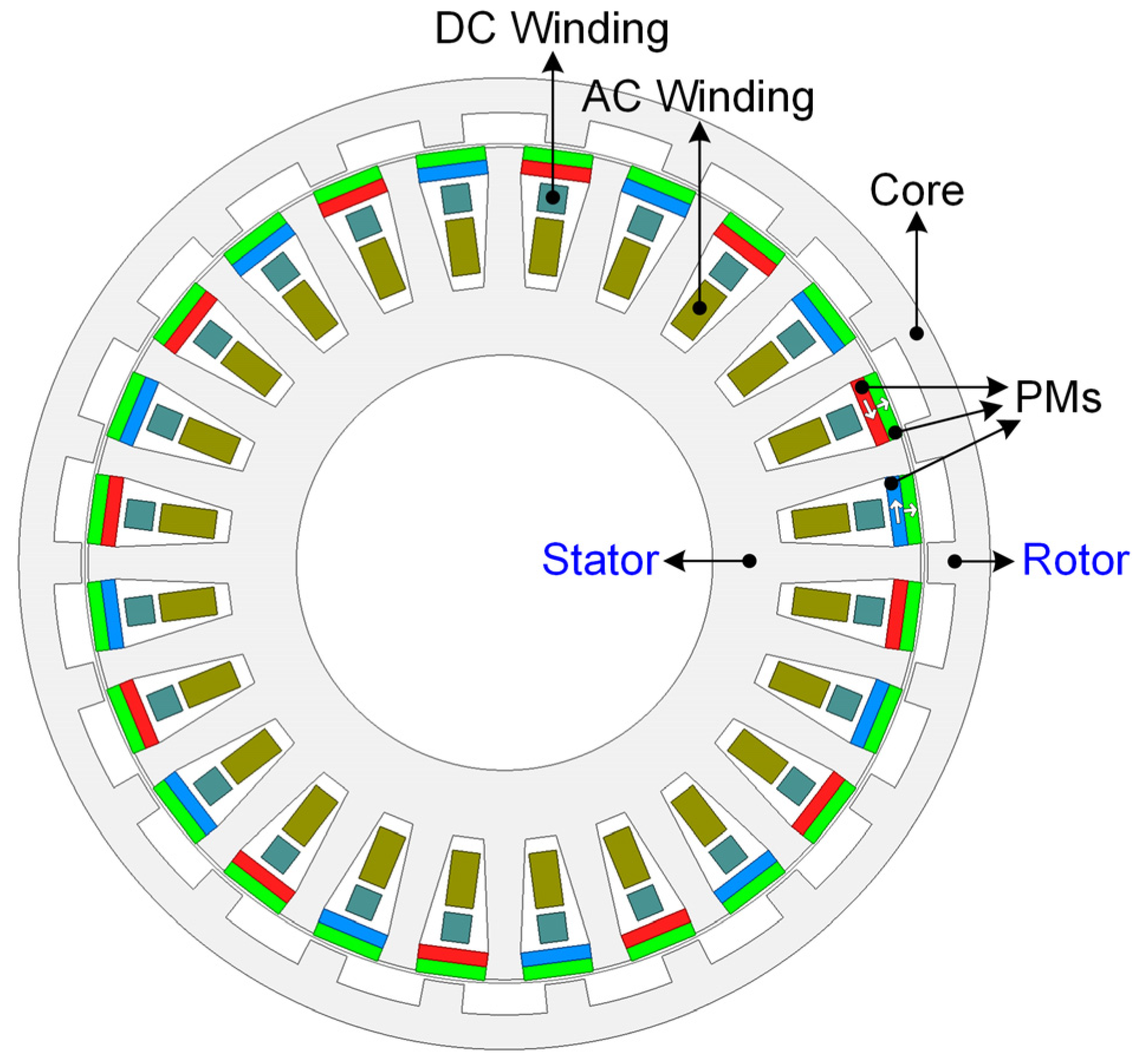
- Hybrid Excited IWMs
4.2. Comparative Study of Selected IWM Topologies
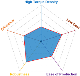
- (a)
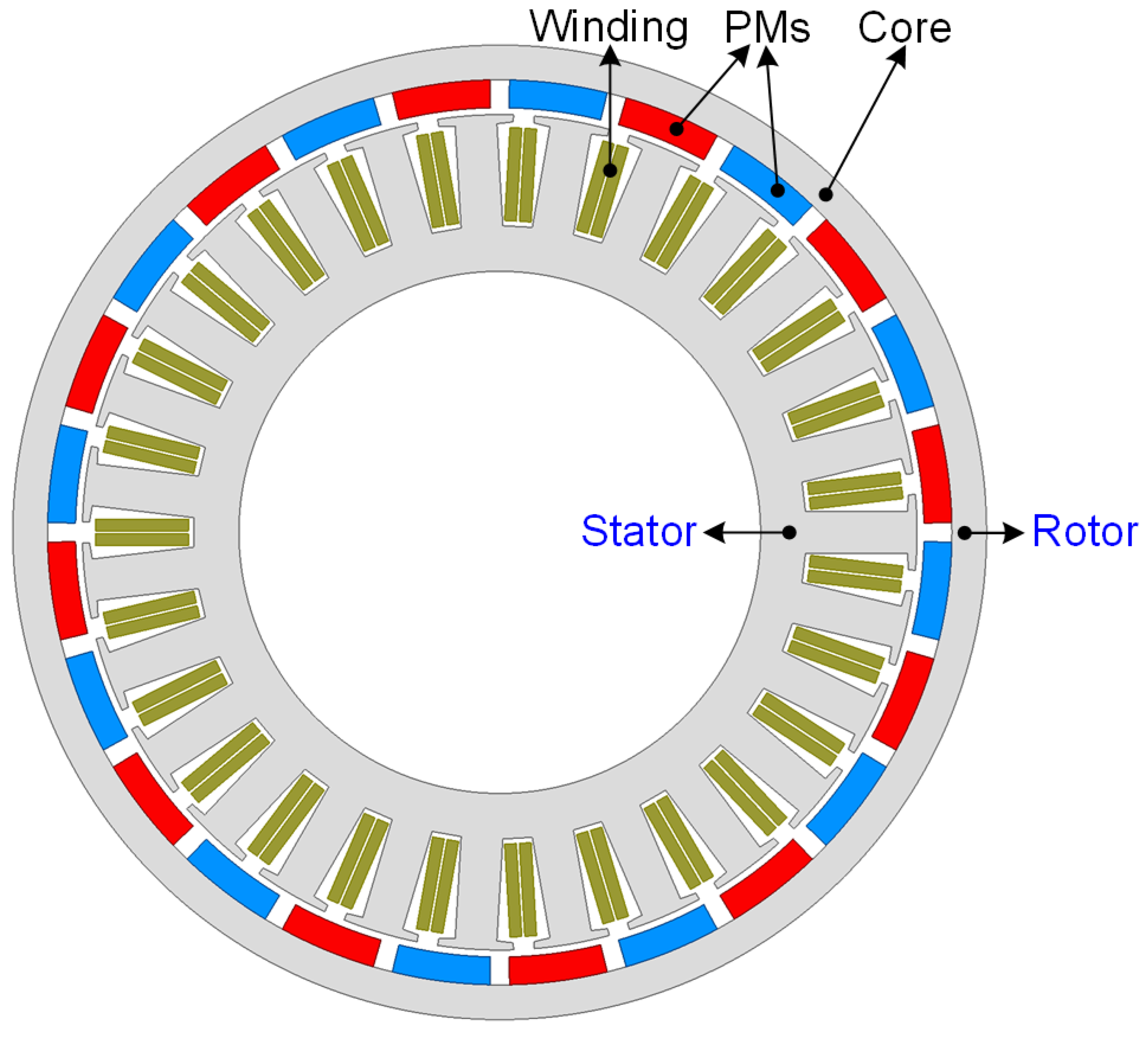
- Fractional Slot Concentrated Winding PMSM-based IWM
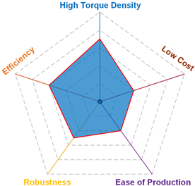
- (b)
- Permanent Magnet Vernier IWM
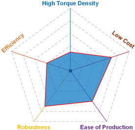
- (c)
- Transverse Flux PM IWM
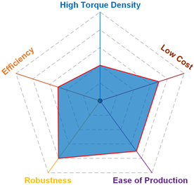
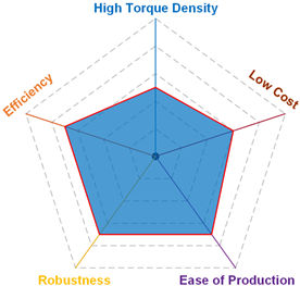
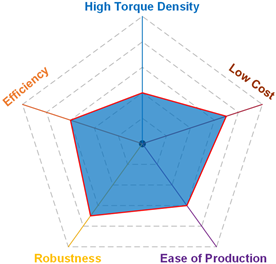
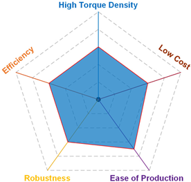
5. Comprehensive Evaluations of the Different IWM Topologies
5.1. Comprehensive Evaluations
- Torque density is uniformly defined as the torque output per unit volume.
- Efficiency refers to motor efficiency and excludes the inverter section.
- Cost measurement encompasses both the materials and manufacturing.
- Reliability metrics include PM demagnetization risk, unbalanced magnetic pull and PM detachment risk, back electromotive force under faults, structural reliability, thermal constraint, torque ripple, etc.
- Ease of assembly is assessed based on existing manufacturing processes.
- Lower torque density and efficiency: Induction motors, switched reluctance motors, synchronous reluctance motors, and consequent-pole motors, despite their excellent reliability and relatively lower manufacturing costs, still lag in torque density, a crucial quality for IWMs. They may be more suitable for other application scenarios, like household appliances.
- Relatively complex manufacturing methods and lower cost-effectiveness: Transverse flux and magnetic gear machines, where industrial applications often prioritize ease of mass production, lack a competitive edge in this aspect, with other aspects also lacking strong persuasiveness.
- Lower power factor: This is prevalent in non-PMSM topologies, potentially exacerbating motor controller costs.
5.2. Discussions
- The flux modulation motor mechanism determines their high torque density. More forms of topologies warrant exploration, considering robustness, efficiency, power factors, and other performance metrics.
- Enhancing the manufacturing processes of AF motors and exploring motor topologies based on manufacturing constraints are crucial to fully leverage the inherent advantages of high torque density in AF motors. Additionally, the operational reliability of AF motors should be a focal point of consideration.
- In addition to motor topologies, new materials [164,165], heat dissipation methods [166], manufacturing processes (such as high-slot fill factor windings and stacking of ultra-thin silicon steel laminations [167]), superconducting windings [168], etc., can all contribute to enhancing motor efficiency, specific power, and torque density to meet the requirements of direct-drive in-wheel applications. This is worth further exploration and research.
6. Conclusions
Author Contributions
Funding
Conflicts of Interest
References
- Cai, S.; Kirtley, J.L.; Lee, C.H.T. Critical Review of Direct-Drive Electrical Machine Systems for Electric and Hybrid Electric Vehicles. IEEE Trans. Energy Convers. 2022, 37, 2657–2668. [Google Scholar] [CrossRef]
- Chau, K.T. Pure Electric Vehicles. In Alternative Fuels and Advanced Vehicle Technologies for Improved Environmental Performance—Towards Zero Carbon Transportation; Folkson, R., Ed.; Woodhead Publishing: Sawston, UK, 2014; pp. 655–684. [Google Scholar]
- Wang, C.; Han, J.; Zhang, Z.; Hua, Y.; Gao, H. Design and Optimization Analysis of Coreless Stator Axial-Flux Permanent Magnet In-Wheel Motor for Unmanned Ground Vehicle. IEEE Trans. Transp. Electrif. 2022, 8, 1053–1062. [Google Scholar] [CrossRef]
- Feng, Y.; Li, F.; Huang, S.; Yang, N. Variable-flux outer-rotor permanent magnet synchronous motor for in-wheel direct-drive applications. Chin. J. Electr. Eng. 2018, 4, 28–35. [Google Scholar] [CrossRef]
- Vassallo, J. On Delivery First Electric Motors in the Scheffler Wheel. Available online: https://techgameworld.com/on-delivery-first-electric-motors-in-the-scheffler-wheel/ (accessed on 31 July 2023).
- Wang, W.; Chen, X.; Wang, J. Motor/Generator Applications in Electrified Vehicle Chassis—A Survey. IEEE Trans. Transp. Electrif. 2019, 5, 584–601. [Google Scholar] [CrossRef]
- Lee, C.H.T.; Chau, K.T.; Cao, L. Development of Reliable Gearless Motors for Electric Vehicles. IEEE Trans. Magn. 2017, 53, 6500308. [Google Scholar] [CrossRef]
- Wenqiang, C.; Chenglin, G. Application status and developing tend of in-wheel motors used for electric automobile. Electr. Mach. Control. Appl. 2007, 34, 1–5. [Google Scholar]
- Peng, H.; Wang, W.; Xiang, C.; Li, L.; Wang, X. Torque coordinated control of four in-wheel motor independent-drive vehicles with consideration of the safety and economy. IEEE Trans. Veh. Technol. 2019, 68, 9604–9618. [Google Scholar] [CrossRef]
- Fan, Y.; Zhu, W.; Zhang, X.; Cheng, M.; Chau, K.T. Research on a Single Phase-Loss Fault-Tolerant Control Strategy for a New Flux-Modulated Permanent-Magnet Compact In-Wheel Motor. IEEE Trans. Energy Convers. 2016, 31, 658–666. [Google Scholar] [CrossRef]
- Li, Z.; Zheng, L.; Gao, W.; Zhan, Z. Electromechanical Coupling Mechanism and Control Strategy for In-Wheel-Motor-Driven Electric Vehicles. IEEE Trans. Ind. Electron. 2019, 66, 4524–4533. [Google Scholar] [CrossRef]
- Oksuztepe, E. In-Wheel Switched Reluctance Motor Design for Electric Vehicles by Using a Pareto-Based Multiobjective Differential Evolution Algorithm. IEEE Trans. Veh. Technol. 2017, 66, 4706–4715. [Google Scholar] [CrossRef]
- Tang, Y.; Chen, L.; Chai, F.; Chen, T. Thermal Modeling and Analysis of Active and End Windings of Enclosed Permanent-Magnet Synchronous In-Wheel Motor Based on Multi-Block Method. IEEE Trans. Energy Convers. 2020, 35, 85–94. [Google Scholar] [CrossRef]
- Cakir, K.; Sabanovic, A. In-wheel motor design for electric vehicles. In Proceedings of the 9th IEEE International Workshop on Advanced Motion Control, 2006, Istanbul, Turkey, 27–29 March; 2006; pp. 613–618. [Google Scholar]
- Zhao, Z.; Taghavifar, H.; Du, H.; Qin, Y.; Dong, M.; Gu, L. In-Wheel Motor Vibration Control for Distributed-Driven Electric Vehicles: A Review. IEEE Trans. Transp. Electrif. 2021, 7, 2864–2880. [Google Scholar] [CrossRef]
- Stefe, B.; Jenko, M. Modeling of Insulation Paper Damage in the Assembly of a Solid Slot Winding. IEEE Access 2020, 8, 27831–27850. [Google Scholar] [CrossRef]
- Ren, H.; Zhang, R. Research and development of in-wheel motor drive technology. J. Chongqing Univ. Technol. 2015, 29, 10–18. [Google Scholar]
- Dobzhanskyi, O.; Gottipati, P.; Karaman, E.; Luo, X.; Mendrela, E.A.; Trzynadlowski, A.M. Multilayer-Winding Versus Switched-Flux Permanent-Magnet AC Machines for Gearless Applications in Clean-Energy Systems. IEEE Trans. Ind. Appl. 2012, 48, 2296–2302. [Google Scholar] [CrossRef]
- Yan, K.; Hu, Z.; Hu, J.; Li, J.; Zhang, B.; Song, J.; Li, J.; Chen, L.; Li, H.; Xu, L.; et al. A critical review of radial field in-wheel motors: Technical progress and future trends. eTransportation 2024, 22, 100353. [Google Scholar] [CrossRef]
- Kim, D.-M.; Benoliel, P.; Kim, D.-K.; Lee, T.H.; Park, J.W.; Hong, J.-P. Framework Development of Series Hybrid Powertrain Design for Heavy-Duty Vehicle Considering Driving Conditions. IEEE Trans. Veh. Technol. 2019, 68, 6468–6480. [Google Scholar] [CrossRef]
- Watts, A.; Vallance, A.; Whitehead, A.; Hilton, C.; Fraser, A. The Technology and Economics of In-Wheel Motors (2010-01-2307). SAE Intern. J. Passeng. Cars-Electron. Electr. Syst. 2010, 3, 37. [Google Scholar] [CrossRef]
- Deshpande, Y.B.; Toliyat, H.A.; Nair, S.S.; Dhinagar, S.J.; Immadisetty, S.; Nalakath, S. High-Torque-Density Single Tooth-Wound Bar Conductor Permanent-Magnet Motor for Electric Two Wheeler Application. IEEE Trans. Ind. Appl. 2015, 51, 2123–2135. [Google Scholar] [CrossRef]
- Yang, F.; Zhao, L.; Yu, Y.; Zhou, C. Analytical description of ride comfort and optimal damping of cushion-suspension for wheel-drive electric vehicles. Int. J. Automot. Technol. 2017, 18, 1121–1129. [Google Scholar] [CrossRef]
- Anderson, M. Unsprung Mass With in-Wheel Motors-Myths and Realities. Proc. AVEC’10 2010, 261, 261–266. [Google Scholar]
- Lovatt, H.C.; Elton, D.; Cahill, L.; Huynh, D.H.; Stumpf, A.; Kulkarni, A.; Kapoor, A.; Ektesabi, M.; Mazumder, H.; Dittmar, T.; et al. Design procedure for low cost, low mass, direct drive, in-wheel motor drivetrains for electric and hybrid vehicles. In Proceedings of the IECON 2011—37th Annual Conference of the IEEE Industrial Electronics Society, Melbourne, Victoria, Australia, 7–10 November 2011; pp. 4558–4562. [Google Scholar] [CrossRef]
- Takahashi, T.; Takemoto, M.; Ogasawara, S.; Hino, W.; Takezaki, K. Size and Weight Reduction of an In-Wheel Axial-Gap Motor Using Ferrite Permanent Magnets for Electric Commuter Cars. IEEE Trans. Ind. Appl. 2017, 53, 3927–3935. [Google Scholar] [CrossRef]
- Lin, F.; Zuo, S.; Deng, W.; Wu, S. Modeling and Analysis of Acoustic Noise in External Rotor In-Wheel Motor Considering Doppler Effect. IEEE Trans. Ind. Electron. 2018, 65, 4524–4533. [Google Scholar] [CrossRef]
- Luo, Y.; Tan, D. Study on the Dynamics of the In-Wheel Motor System. IEEE Trans. Veh. Technol. 2012, 61, 3510–3518. [Google Scholar] [CrossRef]
- Tan, D.; Lu, C. The Influence of the Magnetic Force Generated by the In-Wheel Motor on the Vertical and Lateral Coupling Dynamics of Electric Vehicles. IEEE Trans. Veh. Technol. 2016, 65, 4655–4668. [Google Scholar] [CrossRef]
- Fraser, A. IN-WHEEL ELECTRIC MOTORS: The Packaging and Integration Challenges. In Proceedings of the 10th International CTI Symposium, Berlin, Germany, 5–8 December 2011; pp. 12–23. [Google Scholar]
- Halvorson, B. Here’s Why Ford Nixed In-Wheel Motors in F-150 Lightning Electric Truck. Available online: https://www.greencarreports.com/news/1132317_here-s-why-ford-nixed-in-wheel-motors-in-f-150-lightning-electric-truck (accessed on 17 November 2022).
- Sato, M.; Yamamoto, G.; Gunji, D.; Imura, T.; Fujimoto, H. Development of Wireless In-Wheel Motor Using Magnetic Resonance Coupling. IEEE Trans. Power Electron. 2016, 31, 5270–5278. [Google Scholar] [CrossRef]
- Perovic, D.K. Making the Impossible, Possible—Overcoming the Design Challenges of In Wheel Motors. World Electr. Veh. J. 2012, 5, 514–519. [Google Scholar] [CrossRef]
- Sakai, S.-I.; Sado, H.; Hori, Y. Motion control in an electric vehicle with four independently driven in-wheel motors. IEEE/ASME Trans. Mechatron. 1999, 4, 9–16. [Google Scholar] [CrossRef]
- Xu, G.; Xu, K.; Zheng, C.; Zhang, X.; Zahid, T. Fully electrified regenerative braking control for deep energy recovery and maintaining safety of electric vehicles. IEEE Trans. Veh. Technol. 2015, 65, 1186–1198. [Google Scholar] [CrossRef]
- Xu, W.; Chen, H.; Wang, J.; Zhao, H. Velocity Optimization for Braking Energy Management of In-Wheel Motor Electric Vehicles. IEEE Access 2019, 7, 66410–66422. [Google Scholar] [CrossRef]
- Zhang, X.; Göhlich, D.; Li, J. Energy-Efficient Toque Allocation Design of Traction and Regenerative Braking for Distributed Drive Electric Vehicles. IEEE Trans. Veh. Technol. 2018, 67, 285–295. [Google Scholar] [CrossRef]
- Nishanth, F.; Van Verdeghem, J.; Severson, E.L. A Review of Axial Flux Permanent Magnet Machine Technology. IEEE Trans. Ind. Appl. 2023, 59, 3920–3933. [Google Scholar] [CrossRef]
- Sun, S.; Jiang, F.; Li, T.; Xu, B.; Yang, K. Comparison of a multistage axial flux permanent magnet machine with different stator core materials. IEEE Trans. Appl. Supercond. 2020, 30, 5205906. [Google Scholar] [CrossRef]
- Wang, Y.; Lu, J.; Liu, C.; Lei, G.; Guo, Y.; Zhu, J. Development of a high-performance axial flux PM machine with SMC cores for electric vehicle application. IEEE Trans. Magn. 2019, 55, 8105304. [Google Scholar] [CrossRef]
- Paul, S.; Farshadnia, M.; Pouramin, A.; Fletcher, J.; Chang, J. Comparative analysis of wave winding topologies and performance characteristics in ultra-thin printed circuit board axial-flux pm machine. IET Electr. Power Appl. 2019, 13, 694–701. [Google Scholar] [CrossRef]
- Rallabandi, V.; Han, P.; Wu, J.; Cramer, A.M.; Ionel, D.M.; Zhou, P. Design Optimization and Comparison of Direct-Drive Outer-Rotor SRMs Based on Fast Current Profile Estimation and Transient FEA. IEEE Trans. Ind. Appl. 2021, 57, 236–245. [Google Scholar] [CrossRef]
- Watts, A.; Watts, A.; Vallance, A.; Fraser, A.; Whitehead, A.; Hilton, C.; Monkhouse, H.; Barrie-Smith, J.; George, S.; Ellims, M. Integrating In-Wheel Motors into Vehicles—Real-World Experiences. SAE Int. J. Altern. Powertrains 2012, 1, 289–307. [Google Scholar] [CrossRef]
- Wang, R.; Chen, Y.; Feng, D.; Huang, X.; Wang, J. Development and performance characterization of an electric ground vehicle with independently actuated in-wheel motors. J. Power Sources 2011, 196, 3962–3971. [Google Scholar] [CrossRef]
- Hong, J.; Tan, M.; Zhang, X. Research on Application of In-Wheel Motors on Electric Vehicles. Mech. Electr. Eng. Technol. 2013, 42, 175–178. [Google Scholar] [CrossRef]
- Elaphe. Ltd. Direct-Drive in-Wheel Motors. Available online: https://in-wheel.com/en/ (accessed on 22 June 2022).
- Liang, P.; Chai, F.; Shen, K.; Liu, W. Water Jacket and Slot Optimization of a Water-Cooling Permanent Magnet Synchronous In-Wheel Motor. IEEE Trans. Ind. Appl. 2021, 57, 2431–2439. [Google Scholar] [CrossRef]
- Tan, D.; Xue, H.; Yang, K.; Li, A.; Wang, H. Study on the Thermal Characteristics of In-Wheel Motor Drive System Based on Driving Cycles. IEEE Access 2019, 7, 14463–14471. [Google Scholar] [CrossRef]
- Biček, M.; Pepelnjak, T.; Pušavec, F. Production aspect of direct drive in-wheel motors. Procedia CIRP 2019, 81, 1278–1283. [Google Scholar] [CrossRef]
- Abebe, R.; Vakil, G.; Calzo, G.L.; Cox, T.; Lambert, S.; Johnson, M.; Gerada, C.; Mecrow, B. Integrated motor drives: State of the art and future trends. IET Electr. Power Appl. 2016, 10, 757–771. [Google Scholar] [CrossRef]
- Chen, Q.; Shao, H.; Huang, J.; Sun, H.; Xie, J. Analysis of Temperature Field and Water Cooling of Outer Rotor In-Wheel Motor for Electric Vehicle. IEEE Access 2019, 7, 140142–140151. [Google Scholar] [CrossRef]
- Lipo, T.A. Introduction to AC Machine Design Hoboken; John Wiley & Sons, Inc.: Hoboken, NJ, USA, 2017; p. 507. [Google Scholar]
- Namba, M.; Hiramoto, K.; Nakai, H. Novel Variable-Field Machine with a Three-Dimensional Magnetic Circuit. IEEE Trans. Ind. Appl. 2017, 53, 3404–3410. [Google Scholar] [CrossRef]
- Ifedi, C.J.; Mecrow, B.C.; Brockway, S.T.M.; Boast, G.S.; Atkinson, G.J.; Kostic-Perovic, D. Fault-Tolerant In-Wheel Motor Topologies for High-Performance Electric Vehicles. IEEE Trans. Ind. Appl. 2013, 49, 1249–1257. [Google Scholar] [CrossRef]
- Ifedi, C.J.; Mecrow, B.C.; Widmer, J.D.; Atkinson, G.J.; Brockway, S.T.M.; Kostic-Perovic, D. A high torque density, direct drive in-wheel motor for electric vehicles. In Proceedings of the 6th IET International Conference on Power Electronics, Machines and Drives (PEMD 2012), Bristol, UK, 27–29 March 2012; pp. 1–6. [Google Scholar] [CrossRef]
- Deepak, K.; Frikha, M.A.; Benômar, Y.; El Baghdadi, M.; Hegazy, O. In-Wheel Motor Drive Systems for Electric Vehicles: State of the Art, Challenges, and Future Trends. Energies 2023, 16, 3121. [Google Scholar] [CrossRef]
- Huang, R.; Song, Z.; Zhao, H.; Liu, C. Overview of Axial-Flux Machines and Modeling Methods. IEEE Trans. Transp. Electrif. 2022, 8, 2118–2132. [Google Scholar] [CrossRef]
- Sone, K.; Takemoto, M.; Ogasawara, S.; Takezaki, K.; Akiyama, H. A Ferrite PM In-Wheel Motor without Rare Earth Materials for Electric City Commuters. IEEE Trans. Magn. 2012, 48, 2961–2964. [Google Scholar] [CrossRef]
- Li, T.; Zhang, Y.; Liang, Y.; Ai, Q.; Dou, H. Multiphysics Analysis of an Axial-Flux In-Wheel Motor with an Amorphous Alloy Stator. IEEE Access 2020, 8, 27414–27425. [Google Scholar] [CrossRef]
- Xu, L.; Xu, Y.; Gong, J. Analysis and Optimization of Cogging Torque in Yokeless and Segmented Armature Axial-Flux Permanent-Magnet Machine with Soft Magnetic Composite Core. IEEE Trans. Magn. 2018, 54, 8106005. [Google Scholar] [CrossRef]
- Winterborne, D.; Stannard, N.; Sjöberg, L.; Atkinson, G. An Air-Cooled YASA Motor for in-Wheel Electric Vehicle Applications. IEEE Trans. Ind. Appl. 2020, 56, 6448–6455. [Google Scholar] [CrossRef]
- Madhavan, R.; Fernandes, B.G. Performance Improvement in the Axial Flux-Segmented Rotor-Switched Reluctance Motor. IEEE Trans. Energy Convers. 2014, 29, 641–651. [Google Scholar] [CrossRef]
- Nishanth, F.; Verdeghem, J.V.; Severson, E.L. Recent Advances in Analysis and Design of Axial Flux Permanent Magnet Electric Machines. In Proceedings of the 2021 IEEE Energy Conversion Congress and Exposition (ECCE), Vancouver, BC, Canada, 10–14 October 2021; pp. 3745–3752. [Google Scholar] [CrossRef]
- Hou, J.; Geng, W.; Li, Q.; Zhang, Z. 3-D Equivalent Magnetic Network Modeling and FEA Verification of a Novel Axial-Flux Hybrid-Excitation In-wheel Motor. IEEE Trans. Magn. 2021, 57, 8106912. [Google Scholar] [CrossRef]
- Tak, B.-O.; Ro, J.-S. Analysis and Design of an Axial Flux Permanent Magnet Motor for in-Wheel System Using a Novel Analytical Method Combined with a Numerical Method. IEEE Access 2020, 8, 203994–204011. [Google Scholar] [CrossRef]
- Cavagnino, A.; Lazzari, M.; Profumo, F.; Tenconi, A. A comparison between the axial flux and the radial flux structures for PM synchronous motors. IEEE Trans. Ind. Appl. 2002, 38, 1517–1524. [Google Scholar] [CrossRef]
- Wei, X.; Yang, K.; Pan, Z.; Xie, H.; Zhu, C.; Zhang, Y. Design of a novel axial-radial flux permanent magnet motor. In Proceedings of the 2014 17th International Conference on Electrical Machines and Systems (ICEMS), Hangzhou, China, 22–25 October 2014; pp. 80–84. [Google Scholar] [CrossRef]
- Nasiri-Zarandi, R.; Mirsalim, M.; Tenconi, A. A Novel Hybrid Hysteresis Motor with Combined Radial and Axial Flux Rotors. IEEE Trans. Ind. Electron. 2016, 63, 1684–1693. [Google Scholar] [CrossRef]
- Tsai, M.; Huang, P.; Tsai, M. Research of Axial-Radial Flux Permanent Magnet Integrated Starter/Generator Based on Dual Air-Gap Design. In Proceedings of the 2018 21st International Conference on Electrical Machines and Systems (ICEMS), Jeju, Republic of Korea, 7–10 October 2018; pp. 261–264. [Google Scholar] [CrossRef]
- Jack, A.G.; Mecrow, B.C.; Maddison, C.P. Combined radial and axial permanent magnet motors using soft magnetic composites. In Proceedings of the 1999 Ninth International Conference on Electrical Machines and Drives (Conf. Publ. No. 468), Canterbury, UK, 1–3 September 1999; pp. 25–29. [Google Scholar] [CrossRef]
- Wang, X.; Du, J. Performance Analysis of a Wedgy Airgap Disk Coreless Permanent Magnet Synchronous Motor. In Proceedings of the 2006 International Conference on Mechatronics and Automation, Luoyang, China, 25–28 June 2006; pp. 1811–1816. [Google Scholar] [CrossRef]
- Wang, X.; Tang, R.; Du, J. Optimization of disk coreless permanent magnet synchronous motor based on Halbach-the wedgy airgap motor. Trans. China Electrotech. Soc. 2007, 22, 2–5. [Google Scholar]
- Chen, H.; Demerdash, N.A.O.; Refaie, A.M.E.; Guo, Y.; Hua, W.; Lee, C.H.T. Investigation of a 3D-Magnetic Flux PMSM with High Torque Density for Electric Vehicles. IEEE Trans. Energy Convers. 2022, 37, 1442–1454. [Google Scholar] [CrossRef]
- Linear Labs. Autoblog|The Hunstable Electric Turbine Promises a Revolution in Electric Motors. Available online: https://www.proteanelectric.com/technology/#overview (accessed on 6 December 2024).
- Liang, X.; Ali, M.Z.; Zhang, H. Induction Motors Fault Diagnosis Using Finite Element Method: A Review. IEEE Trans. Ind. Appl. 2020, 56, 1205–1217. [Google Scholar] [CrossRef]
- Bostanci, E.; Moallem, M.; Parsapour, A.; Fahimi, B. Opportunities and Challenges of Switched Reluctance Motor Drives for Electric Propulsion: A Comparative Study. IEEE Trans. Transp. Electrif. 2017, 3, 58–75. [Google Scholar] [CrossRef]
- Murataliyev, M.; Degano, M.; Di Nardo, M.; Bianchi, N.; Gerada, C. Synchronous Reluctance Machines: A Comprehensive Review and Technology Comparison. Proc. IEEE 2022, 110, 382–399. [Google Scholar] [CrossRef]
- Duan, Y.; Ionel, D.M. A Review of Recent Developments in Electrical Machine Design Optimization Methods with a Permanent-Magnet Synchronous Motor Benchmark Study. IEEE Trans. Ind. Appl. 2013, 49, 1268–1275. [Google Scholar] [CrossRef]
- Zhu, X.; Lee, C.H.T.; Chan, C.C.; Xu, L.; Zhao, W. Overview of Flux-Modulation Machines Based on Flux-Modulation Principle: Topology, Theory, and Development Prospects. IEEE Trans. Transp. Electrif. 2020, 6, 612–624. [Google Scholar] [CrossRef]
- Dai, L.; Niu, S.; Gao, J.; Huang, S. Torque Ripple Reduction Design Approach of Permanent Magnet Machines Based on Circumferential Pole Pair Shift. IEEE Trans. Magn. 2025, early access. [Google Scholar] [CrossRef]
- Dai, L.; Niu, S.; Zhang, W.; Gao, J.; Huang, S. Harmonic Modeling and Ripple Suppression of Electromagnetic Torque in IPMSMs. IEEE Trans. Ind. Electron. 2024, 71, 16223–16233. [Google Scholar] [CrossRef]
- Chung, S.-U.; Kim, J.-W.; Chun, Y.-D.; Woo, B.-C.; Hong, D.-K. Fractional Slot Concentrated Winding PMSM with Consequent Pole Rotor for a Low-Speed Direct Drive: Reduction of Rare Earth Permanent Magnet. IEEE Trans. Energy Convers. 2015, 30, 103–109. [Google Scholar] [CrossRef]
- Wang, Q.; Niu, S.; Yang, S. Design Optimization and Comparative Study of Novel Magnetic-Geared Permanent Magnet Machines. IEEE Trans. Magn. 2017, 53, 8104204. [Google Scholar] [CrossRef]
- Niu, S.; Ho, S.L.; Fu, W.N.; Wang, L.L. Quantitative Comparison of Novel Vernier Permanent Magnet Machines. IEEE Trans. Magn. 2010, 46, 2032–2035. [Google Scholar] [CrossRef]
- Husain, T.; Hasan, I.; Sozer, Y.; Husain, I.; Muljadi, E. A Comprehensive Review of Permanent Magnet Transverse Flux Machines: Use in Direct-Drive Applications. IEEE Ind. Appl. Mag. 2020, 26, 87–98. [Google Scholar] [CrossRef]
- Abunike, C.E.; Okoro, O.I.; Far, A.J.; Aphale, S.S. Advancements in Flux Switching Machine Optimization: Applications and Future Prospects. IEEE Access 2023, 11, 110910–110942. [Google Scholar] [CrossRef]
- Yu, Y.; Nakamura, K. Prototype Verification of Flux Reversal Motor with Cross-Pole Shape Stator. IEEE Trans. Magn. 2024, 60, 8204205. [Google Scholar] [CrossRef]
- Zhao, X.; Niu, S.; Fu, W. Design of a Novel Parallel-Hybrid-Excited Dual-PM Machine Based on Armature Harmonics Diversity for Electric Vehicle Propulsion. IEEE Trans. Ind. Electron. 2019, 66, 4209–4219. [Google Scholar] [CrossRef]
- Wang, J.; Atallah, K.; Zhu, Z.Q.; Howe, D. Modular Three-Phase Permanent-Magnet Brushless Machines for In-Wheel Applications. IEEE Trans. Veh. Technol. 2008, 57, 2714–2720. [Google Scholar] [CrossRef]
- Fang, W.; Lu, T.; Wang, M.; Jin, Z.; Lu, S. Control Algorithm Integrated FEM Based Starting Capability Analysis of Induction Motor and PMSM for Electrical Vehicle. In Proceedings of the 2019 IEEE Transportation Electrification Conference and Expo, Asia-Pacific (ITEC Asia-Pacific), Seogwipo, Republic of Korea, 8–10 May 2019; pp. 1–5. [Google Scholar]
- Lipo, T.A.; Liu, W. Comparison of AC Motors to an Ideal Machine Part I—Conventional AC Machines. IEEE Trans. Ind. Appl. 2020, 56, 1346–1355. [Google Scholar] [CrossRef]
- Ghezouani, A.; Gasbaoui, B.; Ghouili, J. Modeling and Sliding Mode DTC of an EV with Four In-Wheel Induction Motors Drive. In Proceedings of the 2018 International Conference on Electrical Sciences and Technologies in Maghreb (CISTEM), Algiers, Algeria, 28–31 October 2018; pp. 1–9. [Google Scholar] [CrossRef]
- Cha, A.H.R.; Jeong, B.T.W.; Im, C.D.Y.; Shin, D.K.J.; Seo, E.Y.J. Design of outer rotor type induction motor having high power density for in-wheel system. In Proceedings of the 2012 15th International Conference on Electrical Machines and Systems (ICEMS), Sapporo, Japan, 21–24 October 2012; pp. 1–4. [Google Scholar]
- Xu, F.; Shi, L. Characteristics analysis of multiple in-wheel-induction-motors drive system. In Proceedings of the 2011 IEEE International Conference on Industrial Technology, Auburn, AL, USA, 14–16 March 2011; pp. 121–126. [Google Scholar] [CrossRef]
- Xue, X.D.; Cheng, K.W.E.; Ng, T.W.; Cheung, N.C. Multi-Objective Optimization Design of In-Wheel Switched Reluctance Motors in Electric Vehicles. IEEE Trans. Ind. Electron. 2010, 57, 2980–2987. [Google Scholar] [CrossRef]
- Upadhyay, P.; Ragavan, K. Design of Two-Phase Switched Reluctance Motor (SRM) for Two-Wheel Electric Vehicle and Torque-Density Based Comparison with Three-Phase SRM. IEEE Trans. Ind. Appl. 2024, 60, 3912–3919. [Google Scholar] [CrossRef]
- Zhu, Y.; Zhao, C.; Zhang, J.; Gong, Z. Vibration Control for Electric Vehicles with In-Wheel Switched Reluctance Motor Drive System. IEEE Access 2020, 8, 7205–7216. [Google Scholar] [CrossRef]
- Anvari, B.; Toliyat, H.A.; Fahimi, B. Simultaneous Optimization of Geometry and Firing Angles for In-Wheel Switched Reluctance Motor Drive. IEEE Trans. Transp. Electrif. 2018, 4, 322–329. [Google Scholar] [CrossRef]
- Chen, Q.; Liao, C.; Ouyang, A.; Li, X.; Xiao, Q. Research and development of in-wheel motor driving technology for electric vehicles. Int. J. Electr. Hybrid Veh. 2016, 8, 242–254. [Google Scholar] [CrossRef]
- Miller, T.J.E. Optimal design of switched reluctance motors. IEEE Trans. Ind. Electron. 2002, 49, 15–27. [Google Scholar] [CrossRef]
- Terashima, M.; Ashikaga, T.; Mizuno, T.; Natori, K.; Fujiwara, N.; Yada, M. Novel motors and controllers for high-performance electric vehicle with four in-wheel motors. IEEE Trans. Ind. Electron. 1997, 44, 28–38. [Google Scholar] [CrossRef]
- Zuo, S.; Lin, F.; Wu, X. Noise Analysis, Calculation, and Reduction of External Rotor Permanent-Magnet Synchronous Motor. IEEE Trans. Ind. Electron. 2015, 62, 6204–6212. [Google Scholar] [CrossRef]
- Reddy, P.B.; Refaie, A.M.E.; Huh, K. Effect of Number of Layers on Performance of Fractional-Slot Concentrated-Windings Interior Permanent Magnet Machines. IEEE Trans. Power Electron. 2015, 30, 2205–2218. [Google Scholar] [CrossRef]
- Bianchi, N.; Fornasiero, E. Impact of MMF Space Harmonic on Rotor Losses in Fractional-Slot Permanent-Magnet Machines. IEEE Trans. Energy Convers. 2009, 24, 323–328. [Google Scholar] [CrossRef]
- Zhang, X.; Zhao, W.; Ji, J.; Zheng, J.; Ling, Z.; Mao, J. Influence of slot-pole configuration on reluctance torque in fractional-slot concentrated-winding interior permanent-magnet machines. Int. J. Appl. Electromagn. Mech. 2017, 54, 525–534. [Google Scholar] [CrossRef]
- Zhang, X.; Ji, J.; Zheng, J.; Zhu, X. Improvement of Reluctance Torque in Fault-Tolerant Permanent-Magnet Machines with Fractional-Slot Concentrated-Windings. IEEE Trans. Appl. Supercond. 2018, 28, 0602205. [Google Scholar] [CrossRef]
- Yang, S.; Baker, N.J.; Mecrow, B.C.; Hilton, C.; Sooriyakumar, G.; Kostic-Perovic, D.; Fraser, A. Cost reduction of a permanent magnet in-wheel electric vehicle traction motor. In Proceedings of the 2014 International Conference on Electrical Machines (ICEM), Berlin, Germany, 2–5 September 2014; pp. 443–449. [Google Scholar] [CrossRef]
- Xie, K.; Li, D.; Qu, R.; Gao, Y. A Novel Permanent Magnet Vernier Machine with Halbach Array Magnets in Stator Slot Opening. IEEE Trans. Magn. 2017, 53, 7207005. [Google Scholar] [CrossRef]
- Gao, Y.; Qu, R.; Li, D.; Li, J.; Zhou, G. Consequent-Pole Flux-Reversal Permanent-Magnet Machine for Electric Vehicle Propulsion. IEEE Trans. Appl. Supercond. 2016, 26, 5200105. [Google Scholar] [CrossRef]
- Chung, S.-U.; Moon, S.-H.; Kim, D.-J.; Kim, J.-M. Development of a 20-Pole–24-Slot SPMSM with Consequent Pole Rotor for In-Wheel Direct Drive. IEEE Trans. Ind. Electron. 2016, 63, 302–309. [Google Scholar] [CrossRef]
- Ma, H.; Wang, W.; Qiu, X.; Yang, J. Inductance Characteristic Analysis of Consequent-Pole Permanent Magnet In-Wheel Motor. IEEE Access 2019, 7, 90507–90516. [Google Scholar] [CrossRef]
- Wang, Y.; Fu, W.; Li, X. A novel axial flux stator and rotor dual permanent magnet machine. CES Trans. Electr. Mach. Syst. 2017, 1, 140–145. [Google Scholar] [CrossRef]
- Chau, K.T.; Zhang, D.; Jiang, J.Z.; Liu, C.; Zhang, Y. Design of a Magnetic-Geared Outer-Rotor Permanent-Magnet Brushless Motor for Electric Vehicles. IEEE Trans. Magn. 2007, 43, 2504–2506. [Google Scholar] [CrossRef]
- Fan, Y.; Zhang, L.; Huang, J.; Han, X. Design, Analysis, and Sensorless Control of a Self-Decelerating Permanent-Magnet In-Wheel Motor. IEEE Trans. Ind. Electron. 2014, 61, 5788–5797. [Google Scholar] [CrossRef]
- Iwaki, K.; Ito, K.; Nakamura, K. A Novel Magnetic-Geared Motor Combining Magnetic Gear and SR Motor. IEEE Trans. Magn. 2023, 59, 8202005. [Google Scholar] [CrossRef]
- Li, J.; Chau, K.T.; Jiang, J.Z.; Liu, C.; Li, W. A New Efficient Permanent-Magnet Vernier Machine for Wind Power Generation. IEEE Trans. Magn. 2010, 46, 1475–1478. [Google Scholar] [CrossRef]
- Jang, D.K.; Chang, J.H. Design of a Vernier Machine with PM on Both Sides of Rotor and Stator. IEEE Trans. Magn. 2014, 50, 877–880. [Google Scholar] [CrossRef]
- Jiang, J.; Niu, S.; Li, Z.; Dai, L.; Wu, W.; Chan, W.L. Design of a Novel Dual-PM Vernier Machine for High-Torque Direct-Drive Application. IEEE Trans. Transp. Electrif. 2024, early access. [Google Scholar] [CrossRef]
- Toba, A.; Lipo, T.A. Generic torque-maximizing design methodology of surface permanent-magnet vernier machine. IEEE Trans. Ind. Appl. 2000, 36, 1539–1546. [Google Scholar] [CrossRef]
- Yu, Y.; Xie, S.; Chai, F.; Pei, Y.; Zhang, X.; Lee, C.H.T. Analysis and Suppression of Core and PM losses in Fractional-Slot Permanent Magnet Vernier Machine and PMSM for In-Wheel Application. IEEE Trans. Ind. Appl. 2025, early access. [Google Scholar] [CrossRef]
- Li, D.; Qu, R.; Lipo, T.A. High-Power-Factor Vernier Permanent-Magnet Machines. IEEE Trans. Ind. Appl. 2014, 50, 3664–3674. [Google Scholar] [CrossRef]
- Li, D.; Qu, R.; Li, J. Topologies and analysis of flux-modulation machines. In Proceedings of the 2015 IEEE Energy Conversion Congress and Exposition (ECCE), Montreal, QC, Canada, 20–24 September 2015; pp. 2153–2160. [Google Scholar]
- Su, S.-B.; Shi, Y.-K.; Yuan, X.-Q.; Han, K.; Cui, T.-T.; Ma, Y. Survey of progress in transverse flux motor. Acta Electonica Sin. 2013, 41, 2290. [Google Scholar]
- Kaiser, B.; Parspour, N. Transverse Flux Machine—A Review. IEEE Access 2022, 10, 18395–18419. [Google Scholar] [CrossRef]
- Arshad, W.M.; Backstrom, T.; Sadarangani, C. Analytical design and analysis procedure for a transverse flux machine. In Proceedings of the IEMDC 2001 IEEE International Electric Machines and Drives Conference (Cat. No.01EX485), Cambridge, MA, USA, 17–20 June 2001; pp. 115–121. [Google Scholar] [CrossRef]
- Henneberger, G.; Bork, M. Development of a new transverse flux motor. In Proceedings of the IEEE Colloquium on New Topologies for Permanent Magnet Machines (Digest No: 1997/090), London, UK, 18 June 1997; pp. 1/1–1/6. [Google Scholar] [CrossRef]
- Baker, N.J.; Atkinson, G.J.; Washington, J.G.; Mecrow, B.C.; Nord, G.; Sjoberg, L. Design of high torque traction motors for automotive applications using modulated pole SMC machines. In Proceedings of the 6th IET International Conference on Power Electronics, Machines and Drives (PEMD 2012), Bristol, UK, 27–29 March 2012; pp. 1–6. [Google Scholar] [CrossRef]
- Martinez-Ocaña, I.; Baker, N.J.; Mecrow, B.C.; Hilton, C.; Brockway, S. Transverse flux machines as an alternative to radial flux machines in an in-wheel motor. J. Eng. 2019, 2019, 3624–3628. [Google Scholar] [CrossRef]
- Anglada, J.R.; Sharkh, S.M. An insight into torque production and power factor in transverse-flux machines. In Proceedings of the 2016 XXII International Conference on Electrical Machines (ICEM), Lausanne, Switzerland, 4–7 September 2016; pp. 120–125. [Google Scholar] [CrossRef]
- Anglada, J.R.; Sharkh, S.M. Analysis of Transverse Flux Machines Using a Virtual Mutual Inductance Approach. IEEE Trans. Energy Convers. 2018, 33, 465–472. [Google Scholar] [CrossRef]
- Bang, D.-J.; Polinder, H.; Shrestha, G.; Ferreira, J.A. Review of generator systems for direct-drive wind turbines. In Proceedings of the European Wind Energy Conference & Exhibition, Brussels, Belgium, 31 March–3 April 2008; pp. 1–11. [Google Scholar]
- Ravichandran, M.; Murali, V.; Vt, S.A.; Joseph, C. A Comprehensive Study on Transverse Flux Motor for Direct Drive Low-Speed Spacecraft Applications. IEEE Trans. Ind. Electron. 2021, 68, 412–422. [Google Scholar] [CrossRef]
- Liu, C.; Lei, G.; Ma, B.; Wang, Y.; Guo, Y.; Zhu, J. Development of a New Low-Cost 3-D Flux Transverse Flux FSPMM with Soft Magnetic Composite Cores and Ferrite Magnets. IEEE Trans. Magn. 2017, 53, 8109805. [Google Scholar] [CrossRef]
- Guo, Y.; Zhu, J.G.; Watterson, P.A.; Wu, W. Development of a PM transverse flux motor with soft magnetic composite core. IEEE Trans. Energy Convers. 2006, 21, 426–434. [Google Scholar] [CrossRef]
- Baker, N.J.; Jordan, S. Comparison of Two Transverse Flux Machines for an Aerospace Application. IEEE Trans. Ind. Appl. 2018, 54, 5783–5790. [Google Scholar] [CrossRef]
- Zhu, X.; Shu, Z.; Quan, L.; Xiang, Z.; Pan, X. Design and Multicondition Comparison of Two Outer-Rotor Flux-Switching Permanent-Magnet Motors for In-Wheel Traction Applications. IEEE Trans. Ind. Electron. 2017, 64, 6137–6148. [Google Scholar] [CrossRef]
- Zhang, H.; Hua, W.; Wu, Z. Modular Spoke-Type Permanent-Magnet Machine for In-Wheel Traction Applications. IEEE Trans. Ind. Electron. 2018, 65, 7648–7659. [Google Scholar] [CrossRef]
- Yang, T.; Paulides, J.J.H.; Lomonova, E.A. Automated Design of DC-Excited Flux-Switching In-Wheel Motor Using Magnetic Equivalent Circuits. IEEE Trans. Magn. 2015, 51, 8103411. [Google Scholar] [CrossRef]
- Su, P.; Hua, W.; Zhang, G.; Chen, Z.; Cheng, M. Analysis and evaluation of novel rotor permanent magnet flux-switching machine for EV and HEV applications. IET Electr. Power Appl. 2017, 11, 1610–1618. [Google Scholar] [CrossRef]
- Lee, C.H.T.; Chau, K.T.; Liu, C.; Ching, T.W.; Li, F. A High-Torque Magnetless Axial-Flux Doubly Salient Machine for In-Wheel Direct Drive Applications. IEEE Trans. Magn. 2014, 50, 8202405. [Google Scholar] [CrossRef]
- Gong, Y.; Chau, K.T.; Jiang, J.Z.; Yu, C.; Li, W. Design of doubly salient permanent magnet motors with minimum torque ripple. IEEE Trans. Magn. 2009, 45, 4704–4707. [Google Scholar] [CrossRef]
- Liu, C.; Chau, K.T.; Li, W. Comparison of fault-tolerant operations for permanent-magnet hybrid brushless motor drive. IEEE Trans. Magn. 2010, 45, 1378–1381. [Google Scholar] [CrossRef]
- Zhao, X.; Niu, S.; Zhang, X.; Fu, W. Flux-Modulated Relieving-DC-Saturation Hybrid Reluctance Machine with Synthetic Slot-PM Excitation for Electric Vehicle In-Wheel Propulsion. IEEE Trans. Ind. Electron. 2021, 68, 6075–6086. [Google Scholar] [CrossRef]
- Zhao, X.; Niu, S.; Zhang, X.; Fu, W. Design of a New Relieving-DC-Saturation Hybrid Reluctance Machine for Fault-Tolerant In-Wheel Direct Drive. IEEE Trans. Ind. Electron. 2020, 67, 9571–9581. [Google Scholar] [CrossRef]
- Huang, S.; Luo, J.; Leonardi, F.; Lipo, T. A comparison of power density for axial flux machines based on general purpose sizing equations. IEEE Trans. Energy Convers. 1999, 14, 185–192. [Google Scholar] [CrossRef]
- Cros, J.; Viarouge, P. Synthesis of high performance PM motors with concentrated windings. IEEE Trans. Energy Convers. 2002, 17, 248–253. [Google Scholar] [CrossRef]
- Yang, S.; Baker, N.J.; Mecrow, B.C.; Smith, D.; Atkinson, G.; Hilton, C.; Perovic, D.K.; Kakavas, I.; Sooriyakumar, G.; Harvey, P. Magnet losses and demagnetisation in a permanent magnet in-wheel electric vehicle traction motor. In Proceedings of the 2015 IEEE International Electric Machines & Drives Conference (IEMDC), Coeur d’Alene, ID, USA, 10–13 May 2015; pp. 1831–1837. [Google Scholar] [CrossRef]
- Refaie, A.M.E. Fractional-Slot Concentrated-Windings Synchronous Permanent Magnet Machines: Opportunities and Challenges. IEEE Trans. Ind. Electron. 2010, 57, 107–121. [Google Scholar] [CrossRef]
- Magnussen, F.; Lendenmann, H. Parasitic Effects in PM Machines with Concentrated Windings. IEEE Trans. Ind. Appl. 2007, 43, 1223–1232. [Google Scholar] [CrossRef]
- Tan, J. Permanent Magnet Brushless DC Motor Technology; Machinery Industry Press: Beijing, China, 2011; p. 335. [Google Scholar]
- Zhu, Z.Q.; Jamil, M.L.M.; Wu, L.J. Influence of slot and pole number combinations on unbalanced magnetic force in permanent magnet machines. In Proceedings of the 2011 IEEE Energy Conversion Congress and Exposition, Phoenix, Arizona, 17–22 September 2011; pp. 3291–3298. [Google Scholar] [CrossRef]
- Zhu, Z.Q.; Jamil, M.L.M.; Wu, L.J. Influence of Slot and Pole Number Combinations on Unbalanced Magnetic Force in PM Machines with Diametrically Asymmetric Windings. IEEE Trans. Ind. Appl. 2013, 49, 19–30. [Google Scholar] [CrossRef]
- Dorrell, D.G.; Popescu, M.; Cossar, C.; Ionel, D. Unbalanced Magnetic Pull in Fractional-Slot Brushless PM Motors. In Proceedings of the 2008 IEEE Industry Applications Society Annual Meeting, Edmonton, AB, Canada, 5–9 October 2008; pp. 1–8. [Google Scholar] [CrossRef]
- Lu, D. Study on Permanent Magnet Brushless Hub Motor Drive System Control for Four-Wheel-Drive Electric Vehicle. Doctor’s Thesis, Tsinghua University, Beijing, China, 2012. [Google Scholar]
- Xie, K.; Li, D.; Qu, R.; Ren, X.; Shah, M.R.; Pan, Y. A New Perspective on the PM Vernier Machine Mechanism. IEEE Trans. Ind. Appl. 2019, 55, 1420–1429. [Google Scholar] [CrossRef]
- Fu, W.N.; Liu, Y. A unified theory of flux-modulated electric machines. In Proceedings of the 2016 International Symposium on Electrical Engineering (ISEE), Hong Kong, China, 14 December 2016; pp. 1–13. [Google Scholar] [CrossRef]
- Ho, S.L.; Niu, S.; Fu, W.N. Design and Comparison of Vernier Permanent Magnet Machines. IEEE Trans. Magn. 2011, 47, 3280–3283. [Google Scholar] [CrossRef]
- Yu, D. Design and Analysis of Permanent Magnet Vernier Machine for In-Wheel Traction Application. Doctor’s Thesis, Zhejiang University, Hangzhou, China, 2019. [Google Scholar]
- Schmidt, E.; Brunnschweiler, D.; Berchten, S. Finite element analysis of a transverse flux machine with an external rotor for wheel hub drives. In Proceedings of the XIX International Conference on Electrical Machines—ICEM 2010, Rome, Italy, 6–8 September 2010; pp. 1–6. [Google Scholar] [CrossRef]
- Jia, Z.; Lin, H.; Yang, H.; Jia, Z.; Mi, C. Transverse flux permanent magnet motor with double-C stator hoops and flux-concentrated rotor for in-wheel drive electric vehicle. In Proceedings of the 2014 IEEE Energy Conversion Congress and Exposition (ECCE), Pittsburgh, PA, USA, 14–18 September 2014; pp. 4804–4808. [Google Scholar] [CrossRef]
- Baserrah, S.; Rixen, K.; Orlik, B. Transverse flux machines with distributed windings for in-wheel applications. In Proceedings of the 2009 International Conference on Power Electronics and Drive Systems (PEDS), Taipei, Taiwan, 2–5 November 2009; pp. 102–108. [Google Scholar] [CrossRef]
- Takizawa, D.; Takahashi, T.; Shimizu, H.; Kato, R. Development of transverse flux motor with improved material and manufacturing method. SAE Int. J. Passeng. Cars-Electron. Electr. Syst. 2013, 6, 366–376. [Google Scholar] [CrossRef]
- Hsu, Y.S.; Tsai, M.C. Development of a Novel Transverse Flux Wheel Motor. IEEE Trans. Magn. 2011, 47, 3677–3680. [Google Scholar] [CrossRef]
- Tsamakis, D.M.; Ionnides, M.G.; Nicolaides, G.K. Torque transfer through plastic bonded Nd2Fe14B magnetic gear system. J. Alloys Compd. 1996, 241, 175–179. [Google Scholar] [CrossRef]
- Gao, X.; Zhang, Y.; Fang, H.; Li, D.; Cheng, Y.; Qu, R. A Novel Topology with the Combination of Superconducting Magnet and Permanent Magnet for the Propulsion Motor of eVTOL Aircraft. IEEE Trans. Appl. Supercond. 2025, 35, 3600605. [Google Scholar] [CrossRef]
- Yu, Y.; Chai, F.; Pei, Y.; Zhang, X.; Lee, C.H.T. Comparative Thermal Analysis of Two Permanent Magnet Machines with Improved Heat Dissipation for in-Wheel Traction Application. IEEE Trans. Ind. Appl. 2025. [CrossRef]
- Infantraj, A.; Augustine, M.; Raj, E.F.I.; Appadurai, M. Investigation of Various Laminating Materials for Interior Permanent Magnet Brushless DC Motor for Cooling Fan Application. CES Trans. Electr. Mach. Syst. 2023, 7, 422–429. [Google Scholar] [CrossRef]
- Kalsi, S.S.; Storey, J.G.; Brooks, J.M.; Lumsden, G.; Badcock, R.A. Superconducting Synchronous Motor Development for Airplane Applications—Mechanical and Electrical Design of a Prototype 100 kW Motor. IEEE Trans. Appl. Supercond. 2023, 33, 5201806. [Google Scholar] [CrossRef]


| Pull Away at 30% Grade | Pull Away at 6% Grade | Braking at 1 g | |
|---|---|---|---|
| Torque | 1300 Nm | 600 Nm | 5000 Nm |
| Power | / | 80 kW | 700 kW |
| Manufacture | Peak Torque (Nm) | Peak Power (kW) | Peak Speed, V (rpm) | Speed Ratio of Reducer, R | Speed Without Reducer V/R (rpm) |
|---|---|---|---|---|---|
| NTN | 60 | 33 | 15,000 | 11 | 1363.6 |
| Toyota | 68 | 40 | 14,400 | 8.5 | 1694.1 |
| ZF | 44 | 40 | 21,600 | 16 | 1350 |
| Schaeffler | 132 | 31 | 4450 | 3.18 | 1399.4 |
| YASA | 390 | 320 | 8000 | 5 | 1600 |
| Manufacture | Peak Torque (Nm) | Peak Power (kW) | Motor Weight (kg) | Torque Density (Nm/kg) | Power Density (kW/kg) |
|---|---|---|---|---|---|
| Shanghai Electric Drive | 640 | 65 | 32 | 20.6 | 2.03 |
| Protean | 1250 | 75 | 36 | 34.7 | 2.08 |
| Elpha | 700 | 60 | 25.2 | 27.8 | 2.38 |
| ENSRTOL ERMAX | 240 | 80 | 12.3 | 19.5 | 6.50 |
| GAC GROUP [45] | 800 | 83 | 31 | 25.8 | 2.7 |
| Elaphe M700 [46] | >700 | 75 | 23 | >30.4 | 3.3 |
| Elaphe M1100 [46] | 1100 | 90 | 40 | 27.5 | 2.3 |
| Elaphe L1500 [46] | 1500 | 110 | 34.8 | 43.1 | 3.2 |
| Requirements | Rated Speed (rpm) | Peak Speed (rpm) | Rated Torque (Nm) | Peak Torque (Nm) |
|---|---|---|---|---|
| Value | 480 | 1500 | 260 | 630 |
| Parameters | |||||
|---|---|---|---|---|---|
| Rotor outer diameter (mm) | Rotor inner diameter (mm) | Core length (mm) | Airgap length (mm) | PM thickness (mm) | |
| Value | 420 | 390.44 | 115 | 0.776 | 4 |
| Rated voltage (V) | Rated Current (A) | Rated torque (Nm) | Rated speed (rpm) | Slot Fill | |
| Value | 150 | 20 | 290 | 800 | 0.43 |
| Turns per coil | Branches | Coil pitch | Core material | PM material | |
| Value | 15 | 1 | 1 | M19-24G | N40UH |
| Parameters | |||||
|---|---|---|---|---|---|
| Rotor outer diameter (mm) | Rotor inner diameter (mm) | Core length (mm) | Airgap length (mm) | PM thickness (mm) | |
| Value | 420 | 393.12 | 115 | 1 | 6.72 |
| Rated voltage (V) | Rated Current (A) | Rated torque (Nm) | Rated speed (rpm) | Slot Fill | |
| Value | 150 | 20 | 290 | 600 | 0.47 |
| Turns per coil | Branches | Coil pitch | Core material | PM material | |
| Value | 40 | 1 | 1 | M19-24G | NdFe35 |
| Parameters | |||||
|---|---|---|---|---|---|
| Rotor outer diameter (mm) | Rotor inner diameter (mm) | Core length (mm) | Airgap length (mm) | PM thickness (mm) | |
| Value | 420 | 393.12 | 115 | 1 | 6.72 |
| Rated voltage (V) | Core material | PM material | Rated speed (rpm) | Rotor poles | |
| Value | 150 | M19-24G | NdFe35 | 600 | 120 |
| RF-FSPMM | RF-PMSM | RF-CPPMSM |
 |  |  |
| RF-PMVM | RF-SRM | TFPMM |
 |  |  |
| RF-IM | RF-MGM | RF-PMaSynRM |
 |  |  |
| AF-IM | AF-PMSM | AF-PMVM |
 |  |  |
Disclaimer/Publisher’s Note: The statements, opinions and data contained in all publications are solely those of the individual author(s) and contributor(s) and not of MDPI and/or the editor(s). MDPI and/or the editor(s) disclaim responsibility for any injury to people or property resulting from any ideas, methods, instructions or products referred to in the content. |
© 2025 by the authors. Licensee MDPI, Basel, Switzerland. This article is an open access article distributed under the terms and conditions of the Creative Commons Attribution (CC BY) license (https://creativecommons.org/licenses/by/4.0/).
Share and Cite
Li, L.; Dai, L.; Niu, S.; Fu, W.; Chau, K.T. Critical Review of Direct-Drive In-Wheel Motors in Electric Vehicles. Energies 2025, 18, 1521. https://doi.org/10.3390/en18061521
Li L, Dai L, Niu S, Fu W, Chau KT. Critical Review of Direct-Drive In-Wheel Motors in Electric Vehicles. Energies. 2025; 18(6):1521. https://doi.org/10.3390/en18061521
Chicago/Turabian StyleLi, Liang, Litao Dai, Shuangxia Niu, Weinong Fu, and K. T. Chau. 2025. "Critical Review of Direct-Drive In-Wheel Motors in Electric Vehicles" Energies 18, no. 6: 1521. https://doi.org/10.3390/en18061521
APA StyleLi, L., Dai, L., Niu, S., Fu, W., & Chau, K. T. (2025). Critical Review of Direct-Drive In-Wheel Motors in Electric Vehicles. Energies, 18(6), 1521. https://doi.org/10.3390/en18061521