Article

Adaptive Gain-Based Double-Loop Full-Order Terminal Sliding Mode Control of a Surface-Mounted PMSM System

1
School of Electrical and Electronic Engineering, Harbin University of Science and Technology, Harbin 150080, China
2
Institute of Electrical Engineering, Chinese Academy of Sciences, Beijing 100190, China
3
CATARC New Energy Vehicle Research and Inspection Center (Tianjin) Co., Ltd., Tianjin 300300, China
*
Author to whom correspondence should be addressed.
Energies 2025, 18(8), 2112; https://doi.org/10.3390/en18082112
Submission received: 18 March 2025 / Revised: 14 April 2025 / Accepted: 18 April 2025 / Published: 19 April 2025

Abstract

:
This article proposes a new adaptive gain, full-order terminal sliding mode control algorithm for the speed regulation of a surface-mounted permanent magnet synchronous motor (SPMSM) control system. To deal with the mismatched uncertainties in the double-loop nonlinear system of the SPMSMs, a virtual control technique is constructed with the full-order terminal sliding mode control to ensure that the tracking error trajectory can converge to equilibrium in finite time. Owing to the integral control law, the output signals of the controllers are smoothed, with the chattering phenomenon attenuated and the gain-margin overestimation avoided. Comprehensive simulation and experimental results have been carried out to demonstrate the superiority of the proposed method in improving tracking accuracy, rapidness, and robustness to the matched and mismatched uncertainties.

1. Introduction

The surface-mounted permanent magnet synchronous motor (SPMSM), renowned for its high power factor and fast dynamic response, is widely used in industrial applications [1,2]. The inherent nonlinear characteristics of the PMSM, coupled with external disturbances such as load torque variations and parameter deviations, render the design of its controller a challenging endeavor. This complexity has motivated the development of diverse control methodologies for PMSM systems, encompassing techniques such as proportional-integral (PI) control, adaptive control, model predictive control, and sliding mode control (SMC) [3,4,5,6,7].
Generally, the mathematical model of the SPMSM belongs to a category of second-order nonlinear systems characterized by both matched and mismatched uncertainties [8,9]. In the field orientation control (FOC) of SPMSMs, the matched uncertainties composed of the parameter variations in the current loops can be compensated by the voltage control law, whereas the mismatched uncertainties containing both parameter variations and load torque fluctuations in the speed loop cannot be handled straightforwardly [10,11]. In existing works, the controllers are generally based on the reduced-order model of the SPMSM without considering the influence of mismatched uncertainties [12,13]. In [12], a model predictive current control based on a sliding mode speed controller is proposed for the PMSM system by designing the speed and current controllers separately. In reference [13], a novel reaching law based on sliding mode control (SMC) is introduced for the speed regulation of PMSMs. However, the current controller is implemented as a PI controller, which fails to account for the second-order characteristics inherent in the PMSM dynamics. Consequently, there is a need for advanced control strategies for the SPMSMs that can effectively counteract the effects of mismatched uncertainties and enhance disturbance rejection capabilities.
Thanks to the strong robustness to external disturbances and low sensitivity to modeling errors and system parameter perturbations, the SMC has attracted significant attention in many applications, especially in the PMSM control system [14,15,16]. Some SMC-based methods have been proposed to deal with mismatched uncertainties [17,18,19,20,21]. In [17], a quasi-sliding mode controller utilizing the saturation function is designed for the PMSM system with mismatched uncertainties. However, the boundary-layer-based SMC would decrease the control accuracy. The integral sliding mode control (ISMC) ensures that system states asymptotically converge to zero [18], while the mismatched disturbances are constrained under the assumptions of being slowly varying or constant [19]. In [20], a disturbance observer-based sliding mode control (DOBSMC) is developed to suppress persistent uncertainties in the system, provided they can be accurately estimated. However, this approach also inherits the restrictive assumptions, like those in ISMC [21]. Both ISMC and DOBSMC commonly rely on the premise that disturbances are either slowly varying or constant, which fundamentally limits the robustness and efficacy of these control methodologies.
The inherent chattering imperfection caused by the high-frequency switching function becomes an extreme restriction in applying SMC [22,23]. In the d- and q-axis current controllers, the output voltages are designed to be smooth, necessarily because the α- and β-axis voltages transformed from the output voltages, regarded as the input signals of the space vector pulse width modulation (SVPWM), must be continuous without chattering. Therefore, a chattering-free algorithm is needed in the control law design for the current controllers. In the speed controller, the output currents must be continuous for two reasons:
  • The d- and q-axis currents cannot track their high-frequency switching references generated by traditional SMC methods.
  • The d- and q-axis voltages contain the derivatives of the d- and q-axis currents, and the derivatives of high-frequency switching currents would lead to singularity [24,25].
Unless the chattering problem can be solved, the traditional SMC should not be directly applied to PMSM control systems. Meanwhile, there is still no SMC-based method that can take into account the smoothness of the output signals in both the speed and the current controllers for PMSM control systems with mismatched uncertainties, although many chattering-free SMC-based methods have already been proposed [26,27,28].
After thoroughly reviewing and analyzing the existing literature, this paper proposes a full-order terminal sliding mode (FOTSM) control algorithm-based virtual control technique for dealing with the matched and mismatched uncertainties in the SPMSM control system. The chattering is attenuated, and the smooth output signals of speed and current controllers can be acquired employing integral control law [29]. The accuracy, rapidness, and anti-disturbance of controllers can be improved, and the high-performance control of the SPMSM control system can be realized. The innovation and challenges can be outlined as follows:
  • Disturbance-rejection performance for both the matched and mismatched uncertainties in SPMSM systems is simultaneously improved when designing the speed and current controllers.
  • The distinctive integral-type control law guarantees continuous control input, which is indicative of rapid and precise system response. This control strategy introduces a distinctive approach to resolving the chattering phenomenon observed in both virtual and real control signals, thereby mitigating the ripple effect in speed and current dynamics.
  • The adaptive switching gain is designed to prevent the overcontrol deficiency caused by the algebraic loop issue and to save energy in the dynamic procedure of the SPMSM control system.
This paper is structured as follows: Section 2 presents the mathematical model of the SPMSM under matched and mismatched disturbances. Section 3 designs the control frameworks based on FOTSM. Section 4 demonstrates simulation and experimental results. Finally, Section 5 provides the concluding remarks.

2. The Model of SPMSM with Uncertainties

The mathematical model of SPMSM is expressed by
ω ˙ = ( 1.5 P n ψ f i q T L ) / J i ˙ q = ( R i q + u s q P n ω ( L i d + ψ f ) ) / L i ˙ d = ( R i d + u s d + P n ω L i q ) / L
where usd,q are the stator voltages of d- and q- axis, and id,q are the stator currents of the d- and q-axis. The d-axis and q-axis inductances of SPMSM are equal to L. R is the stator resistance, ψf the flux linkage, Pn the number of pole pairs, ω the rotor mechanical angular velocity, J the moment of inertia, and TL the load torque.
It defines speed tracking error and current tracking errors as eω = ωrefω, eiq = iqrefiq, eid = idrefid; then, according to (1), the error dynamics can be expressed by
e ˙ ω = ω ˙ r e f G i q + T L / J i ˙ q = P n ω i d P i q Q P n ψ f ω + Q u s q e ˙ i d = P n ω i q + P i d Q u s d
where G = 3Pnψf/(2J), P = R/L,Q = 1/L. The virtual control signal is defined by u ~  = Giqref.
Considering the influence of aging and temperature, the parameters of the SPMSMs may be changed by
R = R 0 + Δ R , L = L 0 + Δ L , J = J 0 + Δ J
where · 0 and · are the nominal and the changed values.
In order to analyze the mismatched and matched uncertainties, some definitions are expressed as
δ = 1 ( J 0 + Δ J ) 1 J 0 = Δ J J 0 ( J 0 + Δ J ) , Δ Q = 1 L 0 + Δ L 1 L 0 = Δ L L 0 ( L 0 + Δ L ) , Δ P = R 0 + Δ R L 0 + Δ L R 0 L 0 = L 0 Δ R R 0 Δ L L 0 ( L 0 + Δ J )
and the boundaries of the uncertainties are assumed by
δ M δ < 1 ,   T L / J M T L / J ,   Δ P M R / L ,   T ˙ L / J M d T L / J , Δ Q M 1 / L ,   u s d , q 2 u e ,   i d , q 2 i e
where Mδ, MTL/J, MR/L, MdTL/J, and M1/L are positive constants, ue is the rated voltage, and ie the rated current.
Therefore, the error dynamics can be rewritten as follows:
e ˙ ω = ω ˙ r e f u ~ + d ω + G e i q i ˙ q = P n ω i d P 0 i q + ( Q 0 + Δ Q ) u s q Q 0 P n ψ f ω + d i q e ˙ i d = P n ω i q + P 0 i d ( Q 0 + Δ Q ) u s d + d i d
where the uncertainties are expressed by
d ω = T L / J δ u ~ ,   d i q = Δ P i q Δ Q P n ψ f ω ,   d i d = Δ P i d
The matched uncertainties and their derivatives are assumed bounded, which should satisfy the following conditions:
d i d M d d ,   d i q M d q ,   d ˙ i d M d d d ,   d ˙ i q M d d q
where
M d d = M R / L i d ,   M d q = M R / L i q + M 1 / L P n ψ f ω M d d d = M R / L ( P 0 i d + ( Q 0 + M 1 / L ) 2 u e + M d d ) M d d q = M R / L ( P 0 i q + ( Q 0 + M 1 / L ) 2 u e + M d q ) + M 1 / L P n ψ f ( 1.5 P n ψ f i q / J + M T L / J )
To achieve decoupling between the d- and q-axis currents and voltages, a feedforward compensation term is developed for the d- and q-axis voltages as follows:
u s = T H + u
where us = [usq, usd]T, u = [uq, ud]T, i = [iq, id]T, T = [0, Pnω/Q; −Pnω/Q, 0], and H = [Pn ψf ω, 0]T.
Therefore, (6) can be reformed into
e ˙ ω = ω ˙ r e f u ~ + d ω + G e i q
i ˙ q = P 0 i q + Q 0 u q + Δ Q u q + d i q
e ˙ i d = P 0 i d Q 0 u d + Δ Q u d + d i d
The block diagram of the FOC system for the SPMSM is presented in Figure 1.
The speed error dynamics and the q-axis current dynamics collectively constitute a second-order, single-input, single-output (SISO) nonlinear system characterized by parameter mismatches and uncertainties.
Lemma 1. 
(Finite-time convergence [30]) Consider the system x ˙ = f(x), f(x) = 0, x ∈ Rn, if there exists a positive definite continuous function V(x): U→R, real number c and α satisfy c > 0, 0 < α < 1, and a neighborhood U0 ⸦ U of the origin such that V ˙ (x) + cVα(x) ≤ 0, x ⸦ U0, then V(x) can converge to zero in a finite time tr, tr ≤ V1−α(x(0))/(c(1 − α)).

3. Controller Design Based on the FOTSM

This paper aims to design a full-order sliding mode-based controller such that the speed can track its reference accurately and rapidly even in the presence of mismatched uncertainties. The full-order sliding mode controller design for the SPMSM can be divided into two steps:
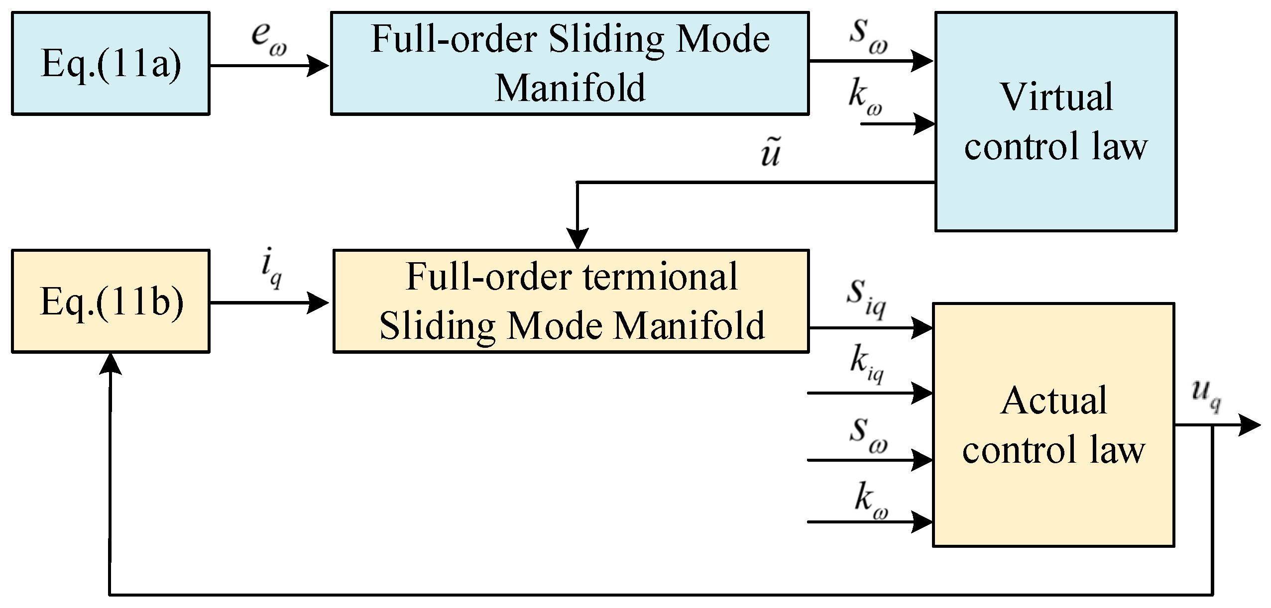
  • The speed controller is designed to make the speed track its reference, i.e., dω can be forced to approach zero rapidly by the VCL ũ. The virtual control technique is synthesized into the design of the speed controller, and the VCL ũ is utilized to cope with the mismatched uncertainties dω;
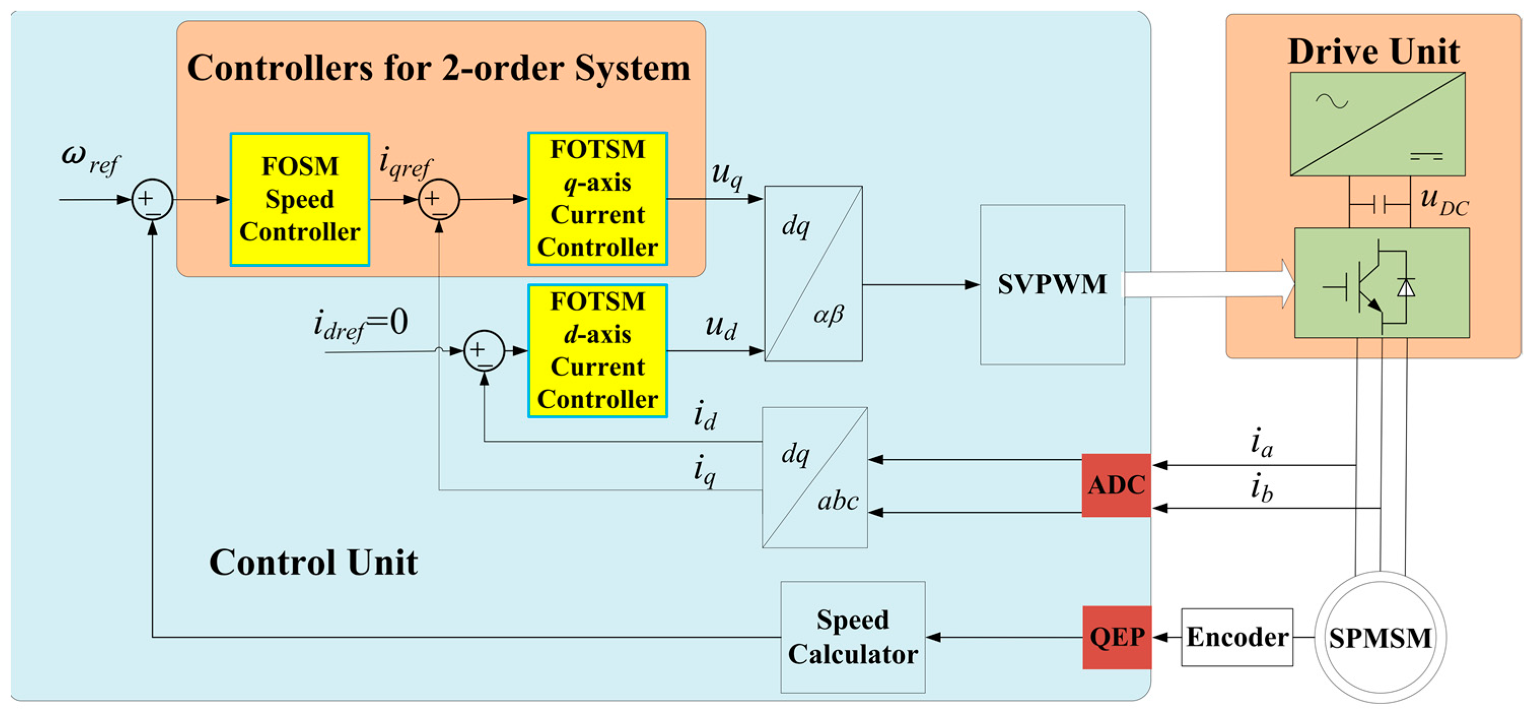
  • In the current loops, the control strategy of iref = 0 is adopted to realize the decoupled control for the FOC system based on the SPMSM. The d- and q-axis current controllers are designed to make the d- and q-axis currents id,q track their references accurately and rapidly. The current errors eid,iq can be forced to converge to zero in finite time by the actual control laws ud,q, which are used to compensate the matched uncertainties did,iq.
For the speed-loop error dynamics (11a), a full-order sliding manifold sω is designed as
s ω = e ˙ ω + C 1 e ω
where C1 is a positive constant.
Remark 1. 
The sliding manifold is designed utilizing the full-order sliding mode (FOSM) approach [29], thus, the error systems behave as desirable full-order dynamics rather than reduced-order dynamics during the sliding-mode motion. The control law can be designed as the integral type, which avoids the introduction of the high-frequency switching signal. Due to eliminating the high-frequency switching signal in the VCL, iqref is a smooth signal, which means the chattering in iqref can be eliminated. Benefitting from the above characteristics, the q-axis current can be forced to track its reference quickly and accurately, and, meanwhile, the singularity problem caused by the derivative of the q-axis reference current can be avoided.
Proposition 1. 
Considering the speed-loop error dynamics (11a), a full-order sliding manifold (12) is defined, and the FOSM speed controller incorporating integral virtual control with adaptive gain is designed, ensuring that the speed error dynamics approach zero provided that the q-axis current error converges to zero. The corresponding equations are detailed as follows:
u ~ = u ~ e q + u ~ n
u ~ e q = ω ˙ r e f + C 1 e ω
u ~ n = 0 t k ω sgn ( s ω ) d τ
k ω = M δ M d ω e q + M d T L / J + η ω 1 M δ
where Mdωeq is the upper bound of ũ and ηω is a positive constant.
Proof. 
Substituting (11), (13a), and (13b) into (12), the full-order sliding manifold is
s ω = ω ˙ r e f u ~ + d ω + G e i q + C 1 e ω = u ~ n δ u ~ n + G e i q + T L / J
Selecting the Lyapunov function Vω = 0.5 s ω 2 and computing its time derivative yields
V ˙ ω = s ω s ˙ ω = s ω u ~ ˙ n s ω δ u ~ ˙ + s ω T ˙ L / J + s ω G e ˙ i q = s ω u ~ ˙ n s ω δ u ~ ˙ n s ω δ u ~ ˙ e q + s ω T ˙ L / J + s ω G e ˙ i q
Combining with the boundaries (5) and the integral switching law (13c) will yield
V ˙ ω k ω ( 1 M δ ) s ω + M δ s ω u ~ ˙ e q + s ω M d T L / J + s ω G e ˙ i q
The derivative of u ~ ˙ e q (13b) can be expressed as
u ~ ˙ e q = ω ¨ r e f + C 1 e ˙ ω
The upper bound of u ~ ˙ e q can be estimated as
u ~ ˙ e q M d ω e q
where Mdωeq can be expressed by
M d ω e q = ω ¨ r e f + C 1 ( ω ˙ r e f + G ( 1 + M δ ) 2 i e + M T L / J )
Then, it will yield
V ˙ ω s ω ( k ω ( 1 M δ ) M δ M d ω e q M d d ) + G s ω e ˙ i q
Considering the adaptive gain (13d), it can yield
V ˙ ω η ω 2 V ω 1 / 2 + G s ω e ˙ i q
According to Lemma 1, it is obvious that if the q-axis current tracking error eiq and its derivative e ˙ i q can converge to zero in finite time by the later Theorem 1, it will yield
V ˙ ω 2 η ω V ω 1 / 2 < 0 ,   for   V ω 0 .
As seen from (22), the speed error dynamics (11a) can reach the sliding manifold sω = 0 in a finite time t ≤ |sω0|/ηω. Afterwards, eω and its derivative e ˙ ω can be forced to asymptotically approach to zero along the manifold sω(t) = 0, where the mismatched uncertainties can be handled by the VCL u ~ . Hence, the proof is completed. □
Considering the q-axis current dynamics in (11b), a full order terminal sliding manifold siq can be constructed by
s i q = e ˙ i q + C 2 e i q p / q
where C2 is a positive constant, and p and q are odd, which should satisfy 0 < p/q < 1.
Theorem 1. 
For the q-axis current dynamics in (11b), a full order terminal sliding manifold in (23) is first chosen. Then, an FOTSM-based q-axis current controller with both the integral actual and virtual control laws in Proposition 1 can be designed, where the q-axis current dynamics can be regulated to reach the ideal sliding motion siq(t) = 0 from the initial condition siq(t) ≠ 0 in finite time trq, trq ≤ |srq(0)|/ηiq, and afterwards, eiq and its derivative e ˙ i q can converge to zero in finite time tsq from any initial condition siq(t) ≠ 0, tsq ≤ trq +q |eiq (trq)|/(C2(q − p)). Related equations can be found by
u q = u q n + u q e q
u q e q = Q 0 1 ( P 0 i q + C 2 e p / q + G 1 ( ω ¨ r e f + C 1 ω ˙ r e f ) ) Q 0 1 G 1 ( C 1 G i q k ω sgn s ω )
u n = 0 t k i q sgn ( s i q ) d τ
k i q = M 1 / L M d q e q + M d d q + G 1 C 1 M d T L / J + η i q Q 0 M 1 / L
where Mdωeq is the upper bound of the derivative of uqeq, as illustrated by
M d q e q = ( P 0 + C 2 ) ( P 0 i q + ( Q 0 + M 1 / L ) 2 u e + M d q )
and ηiq is a positive constant.
Proof. 
Substituting (11b) and (24a) into (23), the full order terminal sliding manifold is reformed into
s i q = i ˙ q r e f + P 0 i q Q 0 u q Δ Q u q d i q + C 2 e i q p / q = Q 0 u q n Δ Q u q d i q + C 1 G 1 d ω
Selecting the Lyapunov function Viq = 0.5 s i q 2 and computing its time derivative yields
V ˙ i q = s i q s ˙ i q = s i q ( Q 0 u ˙ q u + Δ Q u ˙ q + d ˙ i q C 1 G 1 d ˙ ω )
which can then be rewritten as
V ˙ i q = s i q s ˙ i q = s i q ( Q 0 u ˙ q n + Δ Q u ˙ q + d ˙ i q ) + s i q C 1 G 1 ( T ˙ L / J δ u ~ ˙ )
Substituting (24a) into (28) will yield
V ˙ i q = s i q ( Q 0 u ˙ q n + Δ Q u ˙ q n + Δ Q u ˙ q e q + d ˙ i q ) + s i q C 1 G 1 ( T ˙ L / J δ u ~ ˙ ) s i q ( k i q Q 0 + k i q | Δ Q | + | Δ Q | | u ˙ q e q | | d ˙ i q | ) + s i q C 1 G 1 ( | T ˙ L / J | + | δ | | u ~ ˙ | )
According to (13) and (19), the upper bound of ũ is estimated by
| u ~ ˙ | | u ~ ˙ e q | + | u ~ ˙ n | M d ω e q + 2 k ω
Combined with variable switching gain (24d), it will yield
V ˙ i q 2 η i q V 1 / 2 < 0 ,   for   V i q 0 .
The q-axis current dynamics (11b) can reach the sliding manifold siq(t) = 0 from any initial condition siq(t) ≠ 0 in finite time trq ≤ |siq(0)|/ηiq. The total time tsq from siq(t) ≠ 0 to e ˙ i q = 0 and eiq = 0 satisfies
t s q t r q + q | e i q ( t r q ) | 1 p / q / ( C 2 ( q p ) )
The speed-loop error eω can be guaranteed to converge to zero when eiq and e ˙ i q converge to zero. Hence, the proof is completed. □
Remark 2. 
The simple diagram of the FOTSM controller for the second-order SISO system, as proposed in the paper, is shown in Figure 2. Under the action of the integral actual control law, the output signal can be smoothed without the high-frequency switching signal. Hence, the FOTSM can guarantee that the control system has finite-time convergence and a strong disturbance rejection capability to uncertainties.
Considering the d-axis current error dynamics in (11c), it can be assumed to be a first-order system, which means only the matched uncertainties exist. Therefore, a full-order terminal sliding manifold can be constructed by
s i d = e ˙ i d + C 3 e i d p / q
where C3 is a positive constant, and p and q are odd, which should meet 0 < p/q < 1.
Theorem 2. 
For the d-axis current error dynamics (11c), a full-order terminal sliding manifold (33) is selected, and an FOTSM-based d-axis current controller with the integral actual control law and the variable gain is designed, in which the d-axis current error dynamics can reach the ideal sliding motion si (t) = 0 from the initial condition sid (t) ≠ 0 in finite time trd, trd ≤ |sid (0)|/ηid, then eid and its derivative e ˙ i d   can be forced to converge to zero in finite time tsd, tsd ≤ trd +q |eid (trd)|/(C3(q − p)). Related equations can be found by
u d = u d n + u d e q
u d e q = P 0 i d / Q 0
u d n = 0 t k i d sgn ( s i d ) d τ
k i d = M 1 / L M d d e d + M d d d + η i d Q 0 M 1 / L
where Mdqeq is the upper bound of uqeq, as illustrated by
M d q e q = ( P 0 + C 2 ) ( P 0 | i q | + ( Q 0 + M 1 / L ) 2 u e + M d q )
and ηiq is a positive constant.
Proof. 
Substituting (34a) and (34b) into (33), the full order terminal sliding manifold is reformed into
s i d = P 0 i d Q 0 u d Δ Q u d d i d + C 3 e i d p / q = Q 0 u d n Q u d d i d
Selecting the Lyapunov function V i d = 0.5 s i d 2 and computing its time derivative yields
V ˙ i d = s i d s ˙ i d = s i d ( Q 0 u ˙ d n + Δ Q u ˙ d + d ˙ i d )
Substituting (34a) into (37) will yield
V ˙ i d = s i d ( Q 0 u ˙ d n + Δ Q u ˙ d n + Δ Q u ˙ d e q + d ˙ i d ) s i d ( k i d Q 0 + k i d | Δ Q | + | Δ Q | | u ˙ d e q | + | d ˙ i d | )
Combined with (34d) will yield
V ˙ i d 2 η i d V i d 1 / 2 < 0 ,   for   : V i d 0
Similar to Theorem 1, the d-axis current error dynamics in (11c) can reach sid = 0 from any initial condition sid ≠ 0 in a finite time trd, trd ≤ |sid (0)|/ηid. Then, eid and e ˙ id can converge to zero in finite time. The total time from sid ≠ 0 to eid = 0 and e ˙ id = 0 satisfies
t s d t r d + q | e i d ( t r d ) | 1 p / q / ( C 3 ( q p ) )
Hence, the proof is completed. □
Remark 3. 
Using the virtual law ũ and actual laws ud,q, the matched and mismatched uncertainties in the FOC system based on the SPMSM can be thoroughly compensated, which can improve the rapidity, accuracy, and disturbance rejection capability of the SPMSM system.

4. Experiments

To validate the effectiveness of the proposed method, a comprehensive experiment was conducted on an SPMSM experimental platform (Wuhan Heli Changrong Electromechanical Co., Ltd., Wuhan, China) utilizing the TMS320F28335 controller (Texas Instruments, Dallas, TX, USA), driven by an inserted PMSM (IPMSM), as depicted in Figure 3. The SPMSM parameters are provided in Table 1, while the speed and current controller parameters for the three methods are detailed in Table 2. Considering uncertainties arising from aging and temperature variations, the values of R, L, and J in the control algorithm are adjusted to 150% of their nominal values.

4.1. Response to Small Load Addition

A comprehensive comparative analysis is conducted to evaluate the start-up and load addition performance under the three control methods (PI, LSM, and FOTSM). The reference speed is prescribed at 500 rpm, with a load torque of 5 N m introduced at 10 s. As illustrated in Figure 4, the speed and current responses of the three methods are presented for detailed comparison. Observing Figure 4a, the PI method exhibits a significant overshoot of 25.6%, whereas the other two methods demonstrate minimal overshoot. The settling times of the speed response during the initialization phase are recorded as 0.439 s, 0.236 s, and 0.205 s for PI, LSM, and FOTSM, respectively. Upon the application of the load torque at 10 s, the speed degradation under the three methods is measured as 93 rpm, 65 rpm, and 50 rpm, respectively. Furthermore, the recovery period of the speed response under each method is observed to be 0.41 s, 0.38 s, and 0.08 s, respectively. These results indicate that the proposed FOTSM method achieves superior dynamic characteristics in terms of response rapidity and resilience against disturbances compared to the other two methods.
From Figure 4b, it is evident that the q-axis current regulated by FOTSM attains steady state more promptly than the other two approaches. Specifically, the FOTSM exhibits a lower current ripple magnitude compared to LSM, which underscores its enhanced ability to attenuate chattering and produce a smoother output signal, facilitated by the integral control law.

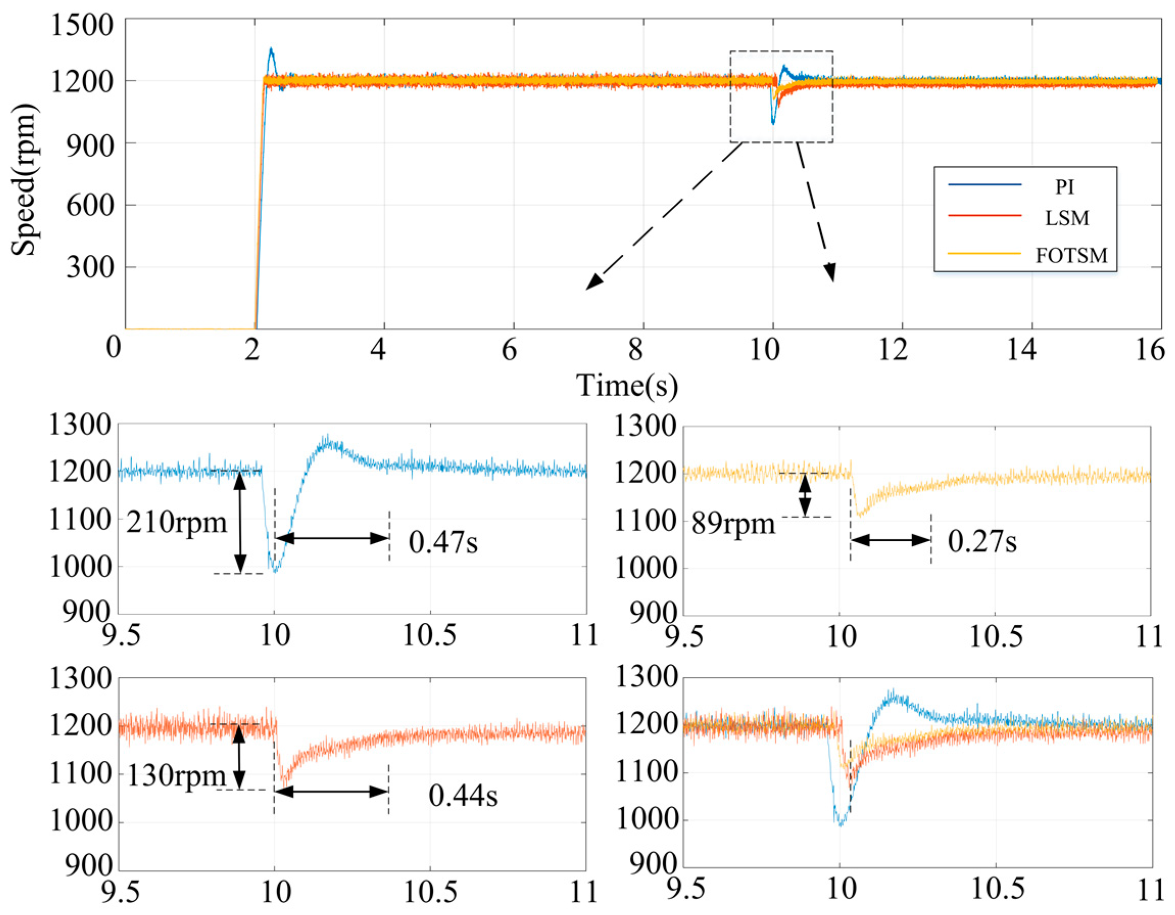
4.2. Response to Large Load Addition

To further investigate the disturbance rejection capability of the proposed approach, an augmented load torque of 10 N m is applied at 10 s. A comparative analysis of the speed and q-axis current responses under the three control methods is presented in Figure 5. As shown in Figure 5a, the speed decrements under the three methods are 115 rpm, 99 rpm, and 53 rpm, respectively. The corresponding response recovery times for the speed are 0.42 s, 0.4 s, and 0.096 s, respectively, which highlights that the FOTSM exhibits superior disturbance rejection capability with faster convergence compared to the other methods. Furthermore, as depicted in Figure 5b, the q-axis current response by FOTSM demonstrates faster dynamic characteristics during both the start-up and load addition processes, outperforming both PI and LSM in terms of response speed. Additionally, the q-axis current ripple by FOTSM is significantly smaller than that by LSM, which further validates the effectiveness of the proposed method in suppressing chattering and achieving smoother current regulation.

4.3. Speed-Reverse Response

The comparison of speed performance under the three methods is shown in Figure 6 under the speed-reverse condition where the reference speed is from 0 rpm to 500 rpm at 2 s, and back to −500 rpm at 10 s. From Figure 6a, it is noted that only the PI has an overshoot of the speed while the other two methods exhibit minimal overshoot during the transient of the speed-reverse operation. The recovery time under the three methods is 0.31 s, 0.35 s, and 0.13 s, respectively, which illustrates that FOTSM has better dynamic performance in rapidity. It can be concluded that the q-axis current ripple and chattering under FOTSM are much smaller than those under LSM.

4.4. High-Speed Response

The speed performances of the SPMSM under the three methods are evaluated under high-speed conditions. The reference speed is set to 1200 rpm, and a load of 5 N m is applied at 10 s. The results clearly demonstrate that only the PI method exhibits an overshoot, while the other two methods do not. Furthermore, the proposed method achieves the reference speed more rapidly than both PI and LSM during the start-up process, as illustrated in Figure 7. The speed drops under the three methods are 210 rpm, 130 rpm and 89 rpm, respectively, when adding the load. The recovery time of the speed response under the three methods is 0.47 s, 0.44 s, and 0.27 s, respectively, which further illustrates that the FOTSM has the best performance in terms of anti-disturbance and rapidity.
Moreover, to make the comparative results more comprehensive in this paper, the improved sliding mode reaching law (SMRL)-based SMC in [26] and predictive function control (PFC) in [31] is shown in Table 3. The reference speeds for both SMRL and PFC are 1600 rpm and 500 rpm. The set values of the load in [26,31] are 5 N m and 2.5 N m. As depicted in Table 3, the proposed method has a slight advantage in rapidness and disturbance rejection capability.

5. Conclusions

This research presents an innovative adaptive-gain FOTSM control strategy tailored for double-loop SPMSM systems subjected to mismatched uncertainties. Our contribution lies in the development of a unique FOTSM-based VCL, which enables high-performance control of the SPMSM system. Distinguishing itself from existing control methods, the proposed approach is derived from the full-order nonlinear mathematical model of the SPMSM, ensuring that both matched and mismatched uncertainties in the system are comprehensively addressed. This enhances the disturbance rejection capability of the SPMSM system significantly. By leveraging the virtual control methodology based on FOTSM, the speed and current tracking errors are driven to converge to zero. The proposed method reveals three significant advantages.
  • The matched and mismatched uncertainties in SPMSM systems are incorporated into the control algorithm design, and the virtual control signal is specially engineered to effectively counteract these uncertainties, ensuring robust control performance under diverse operating conditions.
  • The innovatively designed integral-type law addresses the chattering prompted by high-frequency switching terms, thus deriving smooth current-reference and voltage signals, which are essential for precise system control.
  • The adaptive law for the switching gain is proven highly effective in suppressing the over-control caused by the algebraic loop issue, thus leading to energy savings in the convergence procedure of the SPMSM control system.
Although the control performance of the proposed method is excellent, the definition of the disturbance boundary is too conservative, and an adaptive method can be used to improve it in the future.

Author Contributions

M.Z.: conceptualization, methodology, supervision; X.F.: data curation, visualization, software, validation, writing—original draft; W.X.: conceptualization of this paper, formal analysis, supervision; W.C.: formal analysis, methodology, project administration, resources, supervision; Y.X.: writing—review and editing, validation, investigation; Z.Q.: formal analysis, supervision, validation. All authors have read and agreed to the published version of the manuscript.

Funding

This work is supported by the National Natural Science Foundation of China (under Grant U21A20145); by the National Natural Science Foundation of China (under Grant 52477041); by the Natural Science Foundation for Excellent Young Scholars of Heilongjiang Province (under Grant YQ2024E043); and by the China Postdoctoral Science Foundation (Grant 2023MD744204).

Data Availability Statement

The original contributions presented in this study are included in the article. Further inquiries can be directed to the corresponding author.

Acknowledgments

This research was funded by the New Energy Motor System and Key Materials Innovation Center at Harbin University of Science and Technology.

Conflicts of Interest

Author Zizhen Qiu was employed by the CATARC New Energy Vehicle Research and Inspection Center (Tianjin) Co., Ltd. The remaining authors declare that the research was conducted in the absence of any commercial or financial relationships that could be construed as a potential conflict of interest. The funders had no role in the design of the study; in the collection, analyses, or interpretation of data; in the writing of the manuscript; or in the decision to publish the results.

Abbreviations

The following abbreviations are used in this manuscript:
SPMSMsurface-mounted permanent magnet synchronous motor
VCLvirtual control law
PIproportional-integral
SMCsliding mode control
FOCfield orientation control
ISMCI integral sliding mode control
DOBSMCdisturbance observer-based sliding mode control
SVPWMspace vector pulse width modulation
FOTSMfull-order terminal sliding mode
SISOsingle-input single-output
LSMlinear sliding mode
IPMSMinserted permanent magnet synchronous motor
SMRLsliding mode reaching law

References

  1. Huang, Y.; Liu, S.; Pang, R.; Liu, X.; Rao, X. Model Predictive Current Control for Six-Phase PMSM with Steady-State Performance Improvement. Energies 2024, 17, 5273. [Google Scholar] [CrossRef]
  2. Ji, X.; He, X.; Lv, C.; Liu, Y.; Wu, J. Adaptive-neural-network-based robust lateral motion control for autonomous vehicle at driving limits. Control Eng. Pract. 2018, 76, 41–53. [Google Scholar] [CrossRef]
  3. Seok, J.; Lee, J.K.; Lee, D. Sensorless speed control of nonsalient permanent-magnet synchronous motor using rotor-position-tracking PI controller. IEEE Trans. Ind. Electron. 2006, 53, 399–405. [Google Scholar] [CrossRef]
  4. Peng, H.; Li, J.; Andreas, T.; Deng, K.; Cem, U.; Lars, L.; Kay, H. A scalable, causal, adaptive rule-based energy management for fuel cell hybrid railway vehicles learned from results of dynamic programming. eTransportation 2020, 4, 100057. [Google Scholar] [CrossRef]
  5. Li, L.; Pei, G.; Liu, J.; Du, P.; Pei, L.; Zhong, C. 2-DOF robust H control for permanent magnet synchronous motor with disturbance observer. IEEE Trans. Power Electron. 2021, 36, 3462–3472. [Google Scholar] [CrossRef]
  6. Tan, B.; Li, H.; Zhao, D.; Liang, Z.; Ma, R.; Huangfu, Y. Finite-control-set model predictive control of interleaved DC-DC boost converter Based on Kalman observer. eTransportation 2022, 11, 100158. [Google Scholar] [CrossRef]
  7. Qu, L.; Qiao, W.; Qu, L. An extended-state-observer-based sliding-mode speed control for permanent-magnet synchronous motors. IEEE J. Emerg. Sel. Top. Power Electron. 2021, 9, 1605–1613. [Google Scholar] [CrossRef]
  8. Dai, C.; Guo, T.; Yang, J.; Li, S. A disturbance observer-based current constrained controller for speed regulation of PMSM systems subject to unmatched disturbances. IEEE Trans. Ind. Electron. 2021, 68, 767–775. [Google Scholar] [CrossRef]
  9. Kong, D.; Cai, H.; Zeng, W. Fast Terminal Sliding-Mode Predictive Speed Controller for Permanent-Magnet Synchronous Motor Drive Systems. Energies 2024, 17, 3767. [Google Scholar] [CrossRef]
  10. Pashaei, S.; Badamchizadeh, M. A new fractional-order sliding mode controller via a nonlinear disturbance observer for a class of dynamical systems with mismatched disturbances. ISA Trans. 2016, 63, 39–48. [Google Scholar] [CrossRef]
  11. He, X.; Liu, Y.; Lv, C.; Ji, X.; Liu, Y. Emergency steering control of autonomous vehicle for collision avoidance and stabilisation. Veh. Syst. Dyn. 2019, 57, 1163–1187. [Google Scholar] [CrossRef]
  12. Zhao, K.; Zhou, R.; She, J.; Zhang, C.; He, J.; Li, X. A model predictive current control based on sliding mode speed controller for PMSM. In Proceedings of the 13th International Conference on Human System Interaction Tokyo, Tokyo, Japan, 6–8 June 2020; pp. 229–233. [Google Scholar]
  13. Zhang, Z.; Yang, X.; Wang, W. Enhanced Sliding Mode Control for PMSM Speed Drive Systems Using a Novel Adaptive Sliding Mode Reaching Law Based on Exponential Function. IEEE Trans. Ind. Electron. 2024, 71, 11978–11988. [Google Scholar] [CrossRef]
  14. Yu, X.; Feng, Y.; Man, Z. Terminal sliding mode control-an overview. IEEE Open J. Ind. Electron. Soc. 2021, 2, 36–52. [Google Scholar] [CrossRef]
  15. Zhang, X.; Sun, L.; Zhao, K.; Sun, L. Nonlinear speed control for PMSM system using sliding-mode control and disturbance compensation techniques. IEEE Trans. Power Electron. 2013, 28, 1358–1365. [Google Scholar] [CrossRef]
  16. Liao, Z.; Hao, Y.; Guo, T.; Lv, B.; Wang, Q. Second-Order Sliding Mode Control of Permanent Magnet Synchronous Motor Based on Singular Perturbation. Energies 2022, 15, 8028. [Google Scholar] [CrossRef]
  17. Huang, C.F.; Liao, T.L.; Chen, C.Y.; Yan, J. The design of quasisliding mode control for a permanent magnet synchronous motor with unmatched uncertainties. Comput. Math. Appl. 2012, 64, 1036–1043. [Google Scholar] [CrossRef]
  18. Xu, Q. Digital Integral terminal sliding mode predictive control of piezoelectric-driven motion system. IEEE Trans. Ind. Electron. 2016, 63, 3976–3984. [Google Scholar] [CrossRef]
  19. Do, V.T.; Lee, S. Neural integral backstepping hierarchical sliding mode control for a ridable ballot under uncertainties and input saturation. IEEE Trans. Syst. Man. Cybern. Syst. 2021, 51, 7214–7227. [Google Scholar] [CrossRef]
  20. Yang, J.; Li, S.; Yu, X. Sliding-mode control for systems with mismatched uncertainties via a disturbance observer. IEEE Trans. Ind. Electron. 2013, 60, 160–169. [Google Scholar] [CrossRef]
  21. Chiu, C. Derivative and integral terminal sliding mode control for a class of MIMO nonlinear systems. Automatica 2011, 48, 316–326. [Google Scholar] [CrossRef]
  22. Edwards, C.; Spurgeon, S. Sliding Mode Control: Theory and Applications; CRC Press: Boca Raton, FL, USA, 1998. [Google Scholar]
  23. Shtessel, Y.; Edwards, C.; Fridman, L. Sliding Mode Control and Observation; Springer: New York, NY, USA, 2014; pp. 213–249. [Google Scholar]
  24. Minh Trieu, N.; Tan No, N.; Nguyen Vu, T.; Thinh, N.T. Chattering-Free PID-Nested Nonsingular Terminal Sliding Mode Controller Design for Electrical Servo Drives. Mathematics 2025, 13, 1197. [Google Scholar] [CrossRef]
  25. Yao, Y.; Zhuang, Y.; Xie, Y.; Xu, P.; Wu, C. Prescribed Performance Global Non-Singular Fast Terminal Sliding Mode Control of PMSM Based on Linear Extended State Observer. Actuators 2025, 14, 65. [Google Scholar] [CrossRef]
  26. Junejo, A.K.; Xu, W.; Mu, C.; Ismail, M.; Liu, Y. Adaptive speed control of PMSM drive system based a new sliding-mode reaching law. IEEE Trans. Power Electron. 2020, 35, 12110–12121. [Google Scholar] [CrossRef]
  27. Shi, S.; Gu, J.; Xu, S.; Min, H. Globally fixed-time high-order sliding mode control for new sliding mode systems subject to mismatched terms and its application. IEEE Trans. Ind. Electron. 2020, 67, 10776–10786. [Google Scholar] [CrossRef]
  28. Hou, Q.; Ding, S. GPIO based super-twisting sliding mode control for PMSM. IEEE Trans. Circuits Syst. II-Express Briefs 2021, 68, 747–751. [Google Scholar] [CrossRef]
  29. Feng, Y.; Han, F.; Yu, X. Chattering free full-order sliding-mode control. Automatica 2014, 50, 1310–1314. [Google Scholar] [CrossRef]
  30. Bhat, S.; Bernstein, D. Finite-time stability of continuous autonomous systems. SIAM J. Control Optim. 2000, 38, 751–766. [Google Scholar] [CrossRef]
  31. Liu, H.; Li, S. Speed control for PMSM servo system using predictive functional control and extended state observer. IEEE Trans. Ind. Electron. 2012, 59, 1171–1183. [Google Scholar] [CrossRef]
Figure 1. Block diagram of the FOC system based on the SPMSM.
Energies 18 02112 g001
Figure 2. Simple diagram of the FOTSM controller for the 2-SISO system.
Energies 18 02112 g002
Figure 3. The SPMSM experiment platform.
Energies 18 02112 g003
Figure 4. Responses with the load (5 N m) under PI, LSM, and FOTSM: (a) Speed; (b) q-current.
Energies 18 02112 g004
Figure 5. Responses with the load (10 N m) under PI, LSM, and FOTSM: (a) Speed; (b) q-current.
Energies 18 02112 g005
Figure 6. Responses with the speed-reverse under PI, LSM, and FOTSM: (a) Speed; (b) q-current.
Energies 18 02112 g006
Figure 7. Responses to high speed (1200 rpm) under PI, LSM, and FOTSM.
Energies 18 02112 g007
Table 1. Main parameters of the SPMSM.
SymbolNameValue and Unit
PRated power3 kW
nNRated speed 2000 rpm
PnPolar logarithm3
RStator resistance0.8 Ω
LStator inductance5 mH
JMoment of inertia0.00378 kg·m2
ψfRotor flux linkage0.35 Wb
TRated torque14 N m
ueRated voltage380 V
ieRated current5.2 A
Table 2. Controller design parameters in experiment.
Method Controller NameGain Value
PISpeed PIkp = 50, ki = 20
Current PIkp = 110, ki = 50
linear sliding mode (LSM)Speed LSMs = 10eω, k = 1100
Current PIkp = 50, ki = 30
FOTSMSpeed FOSM s ω = e ˙ ω + 500 e ω , η ω = 15
q-axis current FOTSM s i q = e ˙ i q + 500 e i q 3 / 5 , η i q = 15
d-axis current FOTSM s i d = e ˙ i d + 500 e i d 3 / 5 , η i d = 15
Table 3. Performance comparison of controllers.
ItemsControl SchemePIPFCSMRLFOTSM
Start up-low speedSettling time (s)0.440.24-0.205
Overshoot (%)255.7-0
Add load-low speedSpeed drop (rpm)9336-50
Recovery time (s)0.410.193-0.096
Start up-high speedSettling time (s)0.23-0.0450.133
Overshoot (%)9.2-00
Add load-high speedSpeed drop (rpm)445-39092
Recovery time (s)0.7-0.40.31
Disclaimer/Publisher’s Note: The statements, opinions and data contained in all publications are solely those of the individual author(s) and contributor(s) and not of MDPI and/or the editor(s). MDPI and/or the editor(s) disclaim responsibility for any injury to people or property resulting from any ideas, methods, instructions or products referred to in the content.

