
A Comprehensive Review of Shaft Voltages and Bearing Currents, Measurements and Monitoring Systems in Large Turbogenerators


Abstract
:1. Introduction
2. Shaft Voltage and Bearing Current Phenomena
2.1. Sources of the Shaft Voltage and Bearing Current
2.1.1. Electrostatic Discharge (ESD)
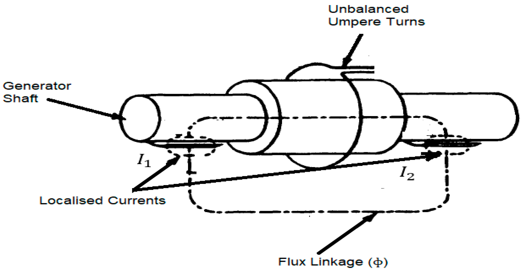
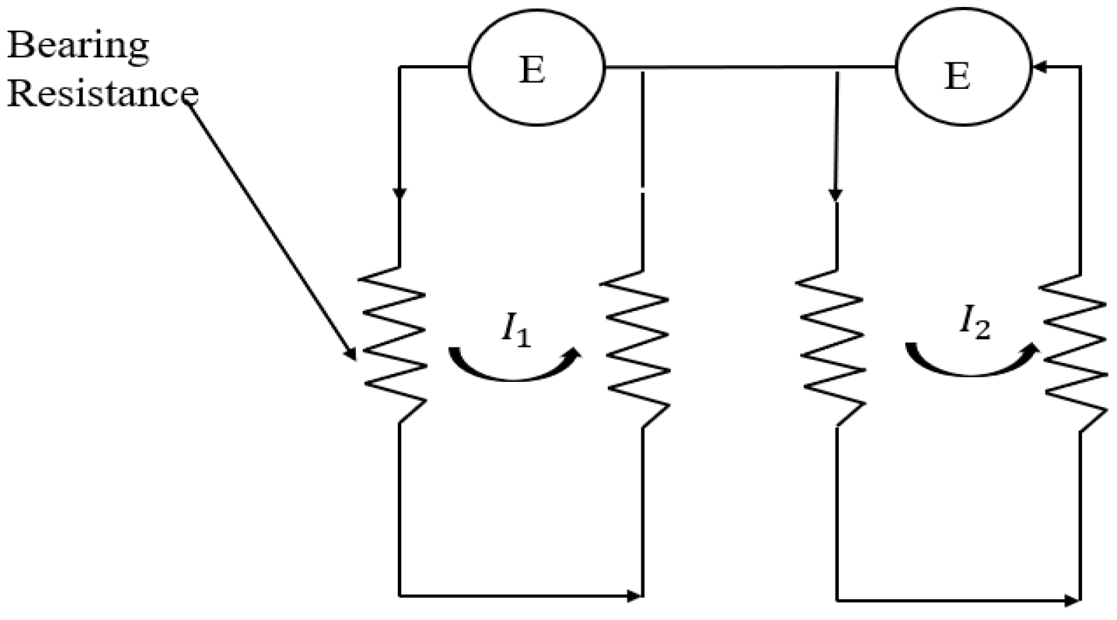
2.1.2. Magnetic Asymmetries in an Electrical Winding
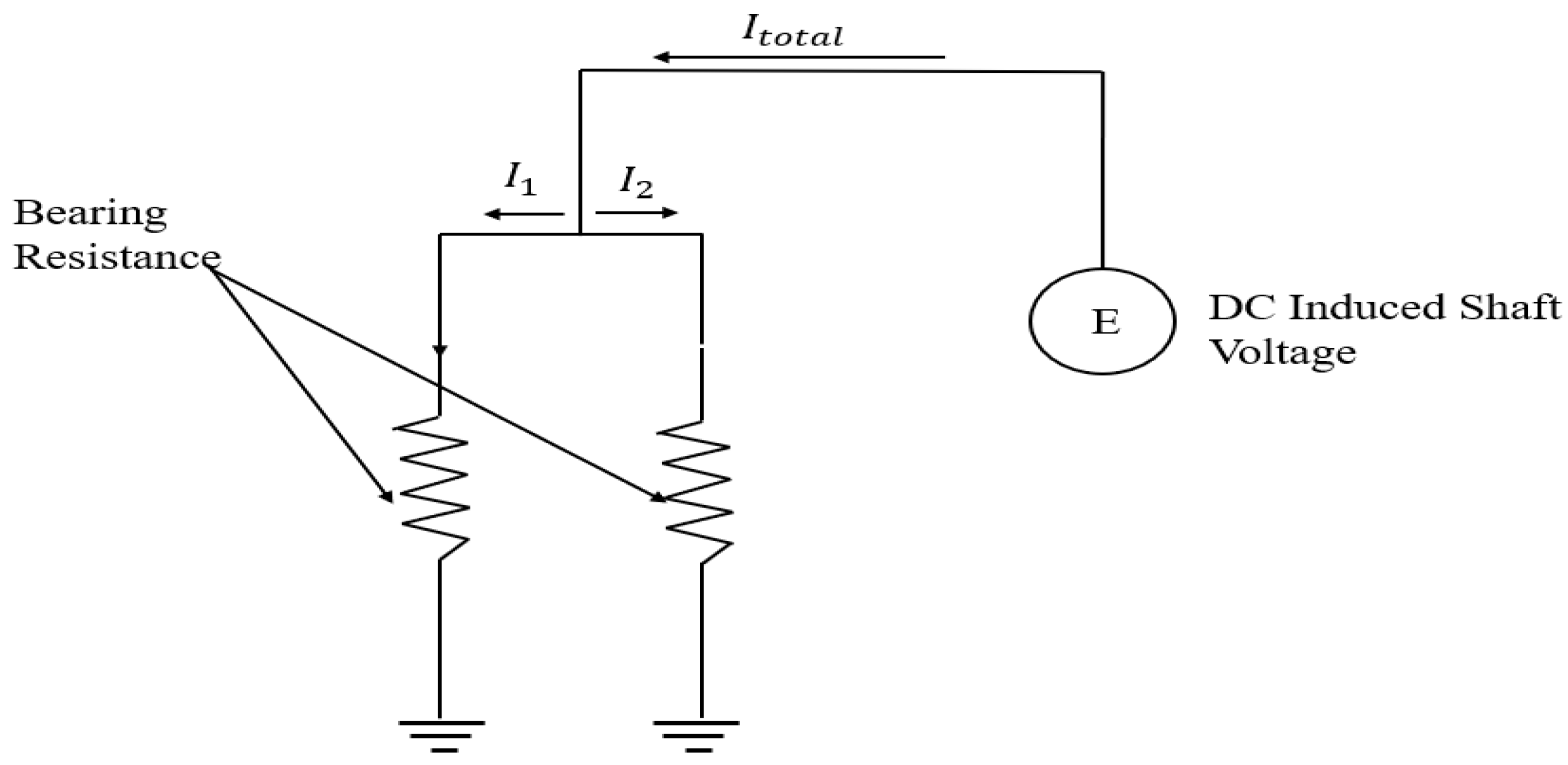
2.1.3. Shaft Magnetization
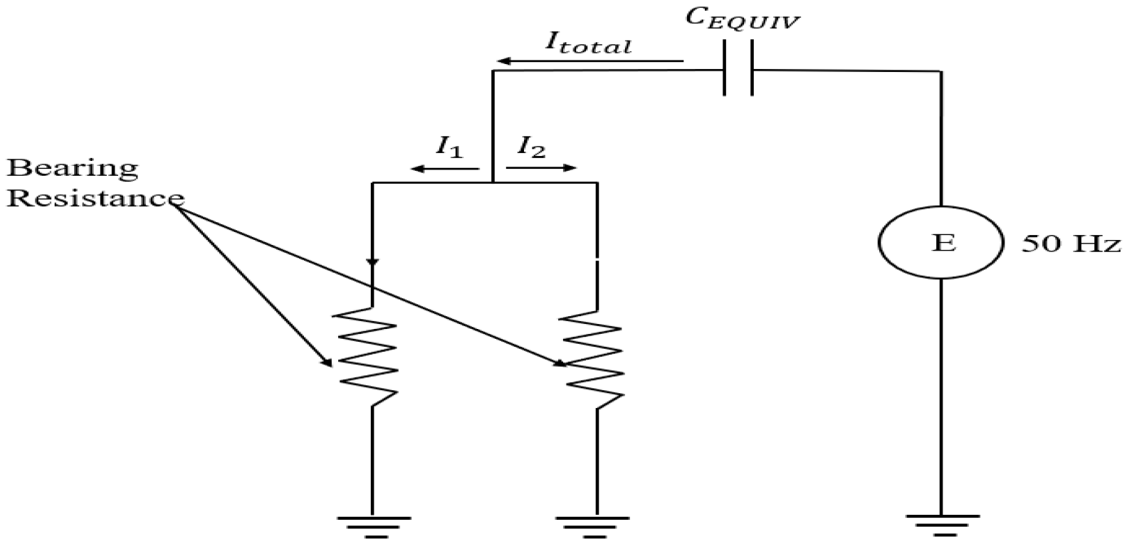
2.1.4. Excitation System Developed Shaft Voltage
2.2. Shaft Voltage Waveform Charecteristics

| Shaft Voltage Source | Mechanism of Generation | Nature of Waveform | Source Impedance | Typical Mitigation Strategies | References |
|---|---|---|---|---|---|
| Electrostatic Discharge | Friction-induced charge accumulation (e.g., wet steam rubbing turbine blades, creating static charge on rotor). | - DC buildup with periodic discharge; - Sawtooth voltage rises and sudden drop (polarity constant, with pulses). | High—generates high voltage (tens to hundreds of volts) but only microamp–milliamp currents (high internal resistance). | - Shaft grounding brushes to bleed off charge; - Maintain oil film strength (prevent oil breakdown and sparking). | [8,26] |
| Magnetic Asymmetry | Asymmetric magnetic flux linkage through shaft (due to design tolerances, air-gap eccentricity, or winding imbalances) causes an induced end-to-end shaft voltage. | AC voltage (alternating) at fundamental machine frequency and its harmonics; continuous sinusoidal-like waveform. | Low—low impedance source (electromagnetic induction) capable of driving large AC circulating currents through bearings and frame. | - Insulate one bearing (usually NDE) to open the circuit; - Minimize magnetic imbalances in design and maintenance. | [3,8] |
| Shaft Magnetization | Residual magnetism in shaft/rotor (from welding, rubs, etc.) produces a homopolar (zero-sequence) flux that induces a DC shaft voltage; can form a self-excited loop through bearings. | - Predominantly DC voltage (steady bias in shaft potential); - In spectrum, appears as a DC component (0 Hz) with minimal alternating content. | - Low—behaves like a low-impedance DC source; - A magnetized rotor can drive continuous DC bearing currents (limited only by circuit resistance). | - Demagnetize shaft/rotor before and during service to eliminate residual magnetism; - Avoid practices that induce magnetization. | [8,27] |
| Excitation-Induced | Common-mode and high-frequency voltages from static excitation system coupling capacitively onto the rotor (field winding to shaft capacitance). Often exacerbated by fast thyristor or diode switching in the exciter. | Mixed DC and AC waveform: a DC offset (from field voltage) plus superimposed high-frequency AC ripple or spikes (e.g., rectifier ripple, switching transients). | - High—the coupling is through small capacitances, so source impedance is high (voltage spikes with negligible steady current); - Significant current flows only during brief discharges. | - High-quality shaft grounding/earthing brushes to clamp shaft potential; - Filters or capacitive shields in the excitation circuit to block or absorb high-frequency components. | [6,7] |
2.3. Shaft Voltage and Bearing Current Implications
2.3.1. Bearings, Seals, and Gears Failures
2.3.2. Reduced Operational Reliability
2.3.3. Costly Repairs and Downtime
2.4. Types of Bearing Currents in Large Turbine Generators
2.4.1. Parasitic Capacitance Quantification
2.4.2. Bearing Currents
- 1.
- Electrostatic Discharge Currents
- 2.
- Grounding Bearing Currents
- 3.
- Capacitive Induced Currents
- 4.
- Circulating Bearing Currents
2.5. Damage of Bearings Caused by Bearing Currents
2.5.1. Source Impedance Classification
2.5.2. Impact on Damage Severity
2.5.3. Bearing Current Damage Type
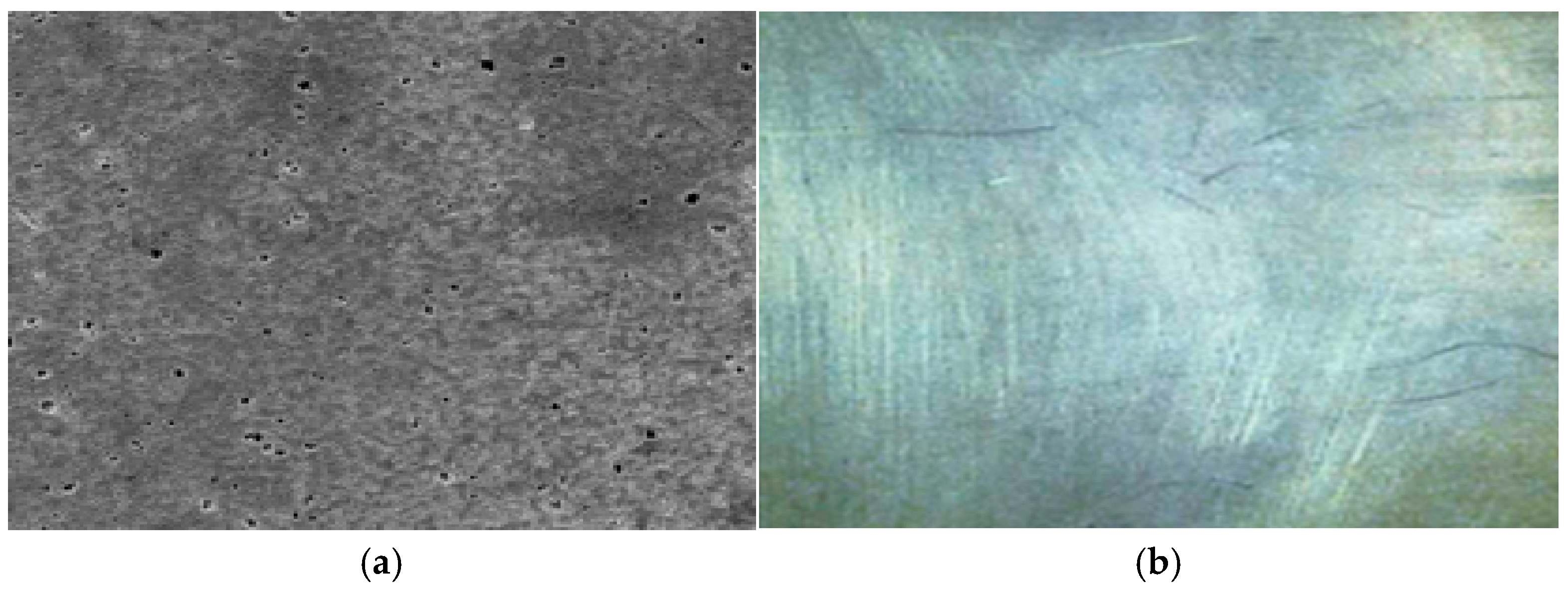
- Frosting: The most common type, caused by electrostatic discharge breaking down the oil film’s resistance;
- Pitting: Similar to frosting but with larger irregularities due to stronger discharge sources. It is less common and affects localized areas;
- Spark Tracks: Visible damage caused by electrical arcing and oil contamination, forming consistent-depth tracks, often aligned with rotation;
- Welding: Occurs due to extremely high circulating currents, leading to severe damage detectable through visual inspection.
2.5.4. Classification of Bearing Currents and Damage Severity
2.5.5. Damage Types and Diagnostic Methods
3. Mitigation of Shaft Voltage-Induced Bearing Failures in Turbine Generators
3.1. Validation of Shaft Voltage Suppression Techniques
3.2. Case Studies on Mitigation Effectiveness
3.3. Scalability of Motor-Based Strategies
3.4. Grounding System Technical Performance Evaluation
3.5. Safety and Technical Standards Considerations Related to Shaft Grounding
- Installed at a single, low-impedance point near the exciter or turbine end;
- Routinely inspected for wear, contamination, and continuity;
- Verified during outages through shaft voltage trending and discharge current logging;
4. Measurement of Shaft Voltage and Bearing Current in Turbine Generators
5. Turbogenerator Condition Monitoring and Health Assessment
5.1. Bearing Current Monitoring and Predictive Fault Detection in Large Generators
5.2. Bearing Current Prediction
5.3. Existing Shaft Voltage and Current Condition Monitoring Tools
5.4. Diagnostic Signal Processing Correlation
5.5. Health Assessment Tools for Turbine Generators
6. Reliability and Maintenance Implications of Shaft Voltage Mitigation
7. Economic Impact of Shaft Voltage and Bearing Current Mitigation
8. Conclusions
- Real-time waveform classification and suppression feedback;
- Scalable implementation of AI-based diagnostics;
- Long-term field validation of grounding materials under harsh environmental conditions.
Author Contributions
Funding
Conflicts of Interest
References
- Stone, G.; Lloyd, B.; Sasic, M. Monitoring of shaft voltages and grounding currents in rotating machines. In Proceedings of the IEEE 17th International Conference Electrical Machine Systems, Hangzhou, China, 22–25 October 2014. [Google Scholar]
- Nippes, P.I.; Elizabeth, P.E.; Galano, S. Understanding Shaft Voltage and Ground Currents of Turbine Generators; Gaussbusters: Holmdel, NJ, USA, 2005; Available online: www.gaussbusters.com (accessed on 5 October 2024).
- White, N.M.; Harvey, T.J.; Wang, L.; Esmaeili, K. Electrical Discharges in Oil-Lubricated Rolling Contacts and Their Detection Using Electrostatic Sensing Technique. Sensors 2022, 22, 392. [Google Scholar] [CrossRef]
- Buckley, G.W.; Corkins, R.J.; Stephens, R.N. The Importance of grounding brushes to safe operations of large turbine generators. IEEE Trans. Energy Convers. 1988, 3, 607–612. [Google Scholar] [CrossRef]
- Pedneault-Desroches, J.; Merkhouf, A.; Al-Haddad, K. Hydrogenerators’ vulnerability towards bearing Insulation systems, shaft voltage and current. In Proceedings of the 2023 IEEE Electrical Insulation Conference (EIC), Quebec City, QC, Canada, 18–21 June 2023. [Google Scholar]
- Verma, S.P. Damages due to shaft-potentials in modern generators. In Proceedings of the Joint International Power Conference Athens Power Tech, Athens, Greece, 5–8 September 2002. [Google Scholar]
- Nippes, P.I. Early warning of developing problems in rotating machinery as provided by monitoring shaft voltages and grounding currents. IEEE Trans. Energy Convers. 2004, 19, 340–345. [Google Scholar] [CrossRef]
- de Canha, D.; Cronje, W.A.; Meyer, A.S.; Hoffe, S.J. Methods for diagnosing static-eccentricity in a synchronous 2 pole generator. In Proceedings of the IEEE Lausanne Power Tech, Lausanne, Switzerland, 1–5 July 2007; pp. 2162–2167. [Google Scholar]
- Ong, R.; Dymond, J.; Findlay, R. Comparison of techniques for measurement of shaft currents in rotating machines. IEEE Trans. Energy Convers. 1997, 12, 363–367. [Google Scholar] [CrossRef] [PubMed]
- Ammann, C.; Posedel, Z.; Joho, R.; Reichert, K. Shaft voltages in generators with static excitation systems—Problems and Solutions. IEEE Trans Energy Convers. 1988, 3, 409–419. [Google Scholar] [CrossRef] [PubMed]
- Datta, A.K.; Dubey, M.; Jain, S. Effect of static power supply in alternator used for short-circuit testing-observation of shaft voltage. IEEE Trans. Power Electron. 2014, 29, 6074–6080. [Google Scholar] [CrossRef]
- Costello, M.J. Shaft voltages and rotating machinery. IEEE Trans. Ind. Appl. 1993, 29, 419–426. [Google Scholar] [CrossRef]
- Muetze, A. On a New type of Inverter-Induced bearing current in large drives with one journal bearing. IEEE Trans. Ind. Appl. 2010, 46, 240–248. [Google Scholar] [CrossRef]
- Alger, P.L.; Samson, H.W. Shaft currents in electric machines. Trans. Am. Inst. Electr. Eng. 1924, 42, 235–245. [Google Scholar] [CrossRef]
- Zhang, S.; Zhang, S.; Wang, B.; Habetler, T.G. Deep Learning Algorithms for Bearing Fault Diagnostics—A Comprehensive Review. IEEE Access 2020, 8, 29857–29881. [Google Scholar] [CrossRef]
- Muetze, A.; Binder, A. Calculation of circulating bearing currents in Machines of Inverter-Based Drive Systems. IEEE Trans. Ind. Electron. 2007, 54, 932–938. [Google Scholar] [CrossRef]
- Pe, T.; Zhang, H.; Hua, W.; Zhang, F. Comprehensive Review of Bearing Currents in Electrical Machines: Mechanisms, Impacts, and Mitigation Techniques. Energies 2025, 18, 517. [Google Scholar] [CrossRef]
- Tawfiq, B.K.; Güleç, M.; Sergeant, P. Bearing current and shaft voltage in electrical machines: A comprehensive research review. Machines 2023, 11, 550. [Google Scholar] [CrossRef]
- Pedneault-Desroches, J.; Merkhouf, A.; Al-Haddad, K. Shaft current diagnostics in large salient-pole generators. In Proceedings of the 2022 IEEE International Conference on Electrical Machines (ICEM), Valencia, Spain, 5–8 September 2022. [Google Scholar]
- Hadden, T.; Jiang, J.W.; Bilgin, B.; Yang, Y.; Sathyan, A.; Dadkhah, H.; Emadi, A. A Review of Shaft Voltages and Bearing Currents in EV and HEV Motors. In Proceedings of the IECON 2016—42nd Annual Conference of the IEEE Industrial Electronics Society, Florence, Italy, 23–26 October 2016; pp. 1578–1583. [Google Scholar]
- Matthias, M.; Kovács, G.; Loinig, M.; Brückl, H. Condition Monitoring of Ball Bearings Based on Machine Learning with Synthetically Generated Data. Sensors 2022, 22, 2490. [Google Scholar] [CrossRef]
- Saad, A.; Usman, A.; Arif, S.; Liwick, M.; Almqvist, A. Bearing Fault Detection Scheme Using Machine Learning for Condition Monitoring Applications. In Proceedings of the International Conference on Mechanical, Automotive and Mechatronics Engineering (ICMAME 2023), Dubai, United Arab Emirates, 29–30 April 2023. [Google Scholar]
- Ilić, D.; Žarković, M.; Stojković, Z. Artificial intelligence system for stator condition diagnostic. Electr. Eng. 2022, 104, 1503–1513. [Google Scholar] [CrossRef]
- Ziemianek, B.M. Steam Turbine Generator Shaft Grounding. Master’s Thesis, Lehigh University, Bethlehem, PA, USA, 1981. [Google Scholar]
- Gruber, J.M.; Hansen, E.F. Electrostatic shaft voltage on steam turbine Rotors. Trans. ASME 1959, 81, 97–210. [Google Scholar] [CrossRef]
- Vance, J.; Palazzolo, A.; Zeidan, F. Electric Shaft Currents in Turbomachinery; Texas A&M University: College Station, TX, USA, 1987; pp. 51–63. [Google Scholar]
- Salazar, M.; Minakata, K.; Reznikov, M. Electrostatic enforcement of steam power plant. In Proceedings of the 2013 IEEE Industry Applications Society Annual Meeting, Lake Buena Vista, FL, USA, 6–11 October 2013. [Google Scholar]
- Mekawey, S.; Snyder, M. Electrostatic Discharge on a Large Steam Turbine Generator. Orbit 2007, 27, 26–35. [Google Scholar]
- Kerszenbaum, I. Shaft currents in electric machines fed by solid-state. In Proceedings of the Industrial and Commercial Power Systems Technical Conference, Pittsburgh, PA, USA, 27–30 April 1992; pp. 71–79. [Google Scholar]
- Nippes, P.I.; Sohre, J.S. Electromagnetic Shaft Currents and Demagnetization on Rotors of Turbines and Compressors; Texas A&M University: College Station, TX, USA, 1978. [Google Scholar]
- Vostrov, K.; Pyrhönen, J.; Ahola, J. Shielding the end windings to reduce bearing currents. In Proceedings of the 2020 International Conference on Electrical Machines (ICEM), Gothenburg, Sweden, 23–26 August 2020. [Google Scholar]
- Oh, H.W.; Willwerth, A. Willwerth Shaft Grounding—A Solution to Motor Bearing Currents. ASHRAE Trans. 2008, 114, 246–251. [Google Scholar]
- Bjekić, M.; Rosić, M.; Bozic, M.; Stojanovic, D. Analysis of mitigation techniques for bearing currents in PWM inverter drives. Metal. Int. 2013, 18, 91–97. [Google Scholar]
- Ahmed, M.S.; Mahdi, H.F. Investigation of bearing current in a Gas Turbine generator due to static excitation system. In Proceedings of the 2013 IEEE Student Conference on Research and Development, Putrajaya, Malaysia, 16–17 December 2015. [Google Scholar]
- Ma, J.; Xue, Y.; Han, Q.; Li, X.; Yu, C. Review on motor bearing damage Induced by bearing current. Machines 2022, 10, 1167. [Google Scholar] [CrossRef]
- Nippes, P.I. Magnetism and stray currents in rotating machinery. Trans. ASME 1996, 118, 228. [Google Scholar] [CrossRef]
- Xie, L.; Yuan, X. Common-Mode Current Reduction at DC and AC Sides in Inverter Systems by Passive Cancellation. IEEE Trans. Power Electron. 2021, 36, 9069–9079. [Google Scholar] [CrossRef]
- Muetze, A.; Oh, H.W. Design aspects of conductive microfiber rings for shaft-grounding purposes. IEEE Trans. Ind. Appl. 2007, 44, 1749–1757. [Google Scholar] [CrossRef]
- Zhu, W.; De Gaetano, D.; Chen, X.; Jewell, G.W.; Hu, Y. A Review of modeling and mitigation techniques for bearing currents in electrical machines with variable-frequency drives. IEEE Access 2022, 10, 125279–125297. [Google Scholar] [CrossRef]
- Ong, R. An Investigation of Shaft Current in a Large Sleeve Bearing Induction Machine. Ph.D. Thesis, McMaster University, Hamilton, ON, Canada, 1999. [Google Scholar]
- Schiferl, R.; Melfi, M. Bearing current remediation options. IEEE Ind. Appl. Mag. 2004, 10, 40–50. [Google Scholar] [CrossRef]
- Berhausen, S.; Jarek, T. Method of limiting shaft voltages in AC electric machines. Energies 2021, 14, 3326. [Google Scholar] [CrossRef]
- Rabuzin, T. Shaft Current Protection. Master’s Thesis, KTH Electrical Ngineering, Stockholm, Sweden, 2015. [Google Scholar]
- Ogasawara, S.; Zhang, S.; Akagi, H. Configurations and characteristics of active canceling and compensating circuits for reducing commonmode voltage generated by voltage-source PWM inverters. In Proceedings of the Conference Record of the 2000 IEEE Industry Applications Conference. Thirty-Fifth IAS Annual Meeting and World Conference on Industrial Applications of Electrical Energy (Cat. No.00CH37129), Rome, Italy, 8–12 October 2002; pp. 57–65. [Google Scholar]
- Ogasawara, S.; Akagi, H.; Ayano, H. An active circuit for cancellation of common-mode voltage generated by a PWM inverter. IEEE Trans. Power Electron. 1998, 13, 835–841. [Google Scholar] [CrossRef]
- User’s Guide, RARIC Shaft-Current Relay; ABB: Zurich, Switzerland, 2004.
- IEEE 112-2017; IEEE Standard Test Procedure for Polyphase Induction Motors and Generators. IEEE: Piscataway, NJ, USA, 2017.
- IEC TS 60034-25; Rotating Electrical Machines—Part 25: AC Electrical Machines Used in Power Drive Systems—Application Guide. Technical Specification IEC TS 60034-25. IEC: Geneva, Switzerland, 2022.
- Sun, Y.; Esmaeli, A.; Sun, L.; Kang, E. Investigation and Suppression of Conducted EMI and Shaft Voltage in Induction Motor Drive System. In Proceedings of the 6th World Congress on Intelligent Control and Automation, Dalian, China, 21–23 June 2006. [Google Scholar]
- Sohre, J.S. Shaft riding brushes to control electric stray currents. In Proceedings of the 20th Turbomachinery Symposium; Turbomachinery Laboratories, Texas A&M University: College Station, TX, USA, 1991; pp. 63–76. [Google Scholar]
- Plazenet, T.; Boileau, T.; Caironi, C.; Nahid-Mobarakeh, B. Comprehensive study on shaft voltages and bearing currents in rotating machines. IEEE Trans. Ind. Appl. 2018, 54, 72–77. [Google Scholar] [CrossRef]
- Chmelik, K.; Cech, V.; Foldyna, J. Devices for prevention of bearings devaluation by electric current. In Proceedings of the 2007 IEEE International Symposium on Diagnostics for Electric Machines, Power Electronics and Drives, Cracow, Poland, 6–8 September 2007. [Google Scholar]
- Shaft Grounding Rings; AEGIS Databook: Mechanic Falls, ME, USA, 2016.
- Copper Braids Generator Health Monitoring Rotor Shaft Voltage for Online Condition Monitoring; GE Power: Atlanta, GA, USA, 2008.
- IEEE 80-2013; IEEE Guide for Safety in AC Substation Grounding. IEEE: Piscataway, NJ, USA, 2015.
- IEC 60034-1:2022; Rotating Electrical Machines. IEC: Geneva, Switzerland, 2022.
- Ray, W.F.; Hewson, C.R. High performance Rogowski current transducers. In Proceedings of the Conference Record of the 2000 IEEE Industry Applications Conference. Thirty-Fifth IAS Annual Meeting and World Conference on Industrial Applications of Electrical Energy, Rome, Italy, 8–12 October 2002; Volume 5, pp. 3083–3090. [Google Scholar]
- Ong, R.; Dymond, J.H.; Findlay, R.D.; Szabados, B. Shaft current in AC induction machine. An online monitoring system and prediction rules. IEEE Trans. Ind. Appl. 2002, 37, 1189–1196. [Google Scholar] [CrossRef]
- Samimi, M.H.; Mahari, A.; Farahnakian, M.A.; Mohseni, H. The Rogowski Coil Principles and Applications: A Review. IEEE Sens. J. 2015, 15, 651–658. [Google Scholar] [CrossRef]
- Nippes, P.I. Shaft Voltage Current Monitoring System for Early Warning and Problem Detection. U.S. Patent 6 460 013B1, 1 October 2002. [Google Scholar]
- Doorsamy, W.; Cronje, W.A.; Meyer, A.S. Multiple fault diagnosis on a synchronous 2 pole generator using shaft and flux probe signals. In Proceedings of the 2013 IEEE International Conference on Industrial Technology (ICIT), Cape Town, South Africa, 25–28 February 2013; pp. 362–367. [Google Scholar]
- Ahola, J.; Sarkimaki, V.; Muetze, A.; Tamminen, J. Radio-frequency based detection of electrical discharge machining bearing currents. IET Elect. Power Appl. 2011, 5, 386–395. [Google Scholar] [CrossRef]
- Sarkimaki, V. Radio Frequency Measurement Method for Detecting Bearing Currents in Induction Motors. Ph.D. Dissertation, Lappeenranta University of Technology, Lappeenranta, Finland, 2009. [Google Scholar]
- Immovilli, F.; Bellini, A.; Rubini, R.; Tassoni, C. Diagnosis of Bearing Faults in Induction Machines by Vibration or Current Signals. In Proceedings of the 2008 IEEE Industry Applications Society Annual Meeting, Edmonton, AB, Canada, 5–9 October 2008; pp. 1350–1359. [Google Scholar]
- Wang, C.; Lu, Z.; Zhou, B. Intelligent fault diagnosis of rolling bearing using hierarchical convolutional network based health state classification. Adv. Eng. Inform. 2017, 32, 139–151. [Google Scholar]
- Su, H.; Xi, W.; Chong, K. Vibration Signal Analysis for Electrical Fault Detection of Induction Machine Using Neural Networks. In Proceedings of the 2007 International Symposium on Information Technology Convergence (ISITC 2007), Jeonju, Republic of Korea, 23–24 November 2007. [Google Scholar]
- Hameed, V.S.; Shameer, K.M. Proactive condition monitoring systems for power plants. Int. J. Sci. Res. Publ. 2013, 3, 2250–3153. [Google Scholar]
- Doorsamy, W.; Cronje, W.A. Optimisation of shaft voltage based condition monitoring in generators using a Bayesian approach. In Proceedings of the 7th IET International Conference on Power Electronics, Machines and Drives (PEMD 2014), Manchester, UK, 8–10 April 2014; IET: Manchester, UK; pp. 1–9. [Google Scholar]
- Rankin, D.R.; Wilson, I. The use of shaft voltage to detect air gap eccentricity and shorted-turns in salient pole alternators. In Proceedings of the 1995 Seventh International Conference on Electrical Machines and Drives (Conf. Publ. No. 412), Durham, UK, 11–13 September 1995; pp. 194–197. [Google Scholar]
- Torlay, J.-E.; Corenwinder, C.; Audoli, A.; Herigault, J.; Foggia, A. Analysis of shaft voltages in large synchronous generators. In Proceedings of the IEEE International Electric Machines and Drives Conference (IEMDC’99), Seattle, WA, USA, 9–12 May 1999. [Google Scholar]
- Darques, K.; Tounzi, A.; Menach, Y.L.; Beddek, K. Analysis of shaft voltage of large turbo-generators for rotor defect detection purposes. In Proceedings of the 19th International Symposium on Electromagnetic Fields in Mechatronics, Electrical and Electronic Engineering (ISEF), Nancy, France, 29–31 August 2019. [Google Scholar]
- Hsu, J.S.; Stein, J. Shaft signal of salient pole synchronous machines for eccentricity and short field coil detections. IEEE Trans. Energy Convers. 1994, 9, 572–578. [Google Scholar] [CrossRef]


| Shaft Voltage Source | Impedance and Discharge Characteristics | Typical Damage Potential | References |
|---|---|---|---|
| Electrostatic buildup (e.g., friction of steam turbine blades) | High source impedance—can reach tens to ~100 V on shaft but only μA–mA discharge currents. Discharges are intermittent (charge–breakdown cycles) and unipolar. | Gradual pitting and frosting over time due to repetitive sparks. Fluting patterns may develop as microscopic pits accumulate. Generally, no immediate catastrophic damage, but progressive erosion and lubricant contamination occur if unmitigated. | [6,12] |
| Magnetic asymmetry (induced circulating AC) | Low source impedance—typically <1 V induced, but the shaft-frame loop offers a very low resistance. Even a few millivolts can drive high AC currents (tens of A) through bearings. Discharges can occur every half-cycle if a path is present. | Rapid frosting and fluting of bearing races due to continuous spark erosion at line frequency. Can lead to pronounced washboard patterns in a short time. Potential for spark tracks or thermal damage if currents are very high. | [6,12] |
| Shaft magnetization (homopolar DC shaft voltage) | The system has low source impedance and produces a steady DC voltage (typically a few millivolts to ~1 V) due to an internal DC generator effect. With minimal resistance in the metal path, significant continuous current can flow if a closed loop exists. | DC circulating currents can cause localized pitting, continuous arcing, and electrical wear at contact points, leading to unidirectional bearing fluting or material transfer. Prolonged exposure may result in uneven wear or even welding. | [12,30] |
| Excitation system and converter-induced common-mode (e.g., static exciters, inverter drives) | Moderate-to-high impedance at DC, but low impedance at high frequency. Imposes a DC bias plus fast voltage transients (dv/dt in kV/μs range). The capacitive coupling allows high-frequency discharge pulses (EDM events). | Electric discharge machining (EDM) effects on bearings, frequent high-frequency sparks cause fluting, pitting, and erosion of races. Can lead to premature bearing failure similar to high-impedance electrostatic cases but occurring at high repetition rates. | [6,10] |
| Shaft Voltage Source Type | Bearing Current Damage Type | Mitigation Techniques |
|---|---|---|
| High Impedance Source | Pitting and Frosting—Initial fine pits develop into a frosted appearance, removing top metal surfaces. | Shaft grounding, insulated bearings, filters, optimized machine design, monitoring, and maintenance. |
| Contaminated lubrication oil damage | Improved lubrication, sealed bearing housings, oil monitoring, synthetic lubricants, contamination prevention. | |
| Low Impedance Source | Pitting and Frosting—Higher current levels cause severe damage in a shorter time compared to high-impedance sources. | Shaft grounding, insulated bearings, filters, optimized. |
| Spark Tracking—Electrical discharges leave visible scratch-like marks; melted metal at the track bottom. | Shaft grounding rings, carbon brushes, common-mode chokes, ceramic-coated bearings, hybrid bearings, real-time monitoring. | |
| Welding—Excessive shaft current causes localized heating, welding metal surfaces together, leading to catastrophic failure. | Low-impedance grounding, electrically insulated bearings, high-resistance greases, monitoring, and diagnostics. | |
| Contaminated Lubrication Oil Damage—Higher particle concentration in oil leads to severe wear and damage. | Improved lubrication, sealed bearing housings, oil monitoring, synthetic lubricants, contamination prevention. |
| Severity Stage | Current Range | Frequency Content | Damage Type | Typical Source | References |
|---|---|---|---|---|---|
| Stage 1—Pitting | <10 mA | HF (1–20 kHz), sporadic | Small craters, light erosion | Electrostatic discharge, HF ripple | [11,12,35] |
| Stage 2—Frosting | 10–50 mA | HF or AC (50 Hz) repetitive | Surface dullness, lubricant damage | HF excitation-induced currents | [6,12,43] |
| Stage 3—Fluting | >50 mA | 50/60 Hz (line frequency) | Grooving/fluting pattern | Magnetic asymmetry, circulating current loop | [12,30,43] |
| Stage 4—Welding | >100 mA | DC or AC | Severe arc damage, welding | Shaft magnetization, ground fault loops | [6,10,43] |
| Sources | Solution | Description | Merits | Drawbacks | References |
|---|---|---|---|---|---|
| High-impedance source | Insulated bearings | Use insulated bearings at the non-drive end to block circulating shaft currents. | Effectively isolates bearings from shaft currents, reducing damage risk. | High cost, complex installation, potential mechanical performance impact. | [5,43,52] |
| Shaft grounding brushes | Install grounding brushes on the rotor shaft to provide a low-impedance discharge path. | Cost-effective, easy to install, widely used in generators. | Brushes wear out over time, requiring regular replacement and maintenance. | [1,2,3,4,30] | |
| RC shaft earthing circuit | Use of a resistor-capacitor (RC) circuit to ground the shaft and dissipate high-frequency currents. | Reduces transient voltage buildup, prevents excessive shaft voltages. | Requires careful tuning of RC components, not effective for all voltage ranges. | [10,34] | |
| Low-impedance source | Bonding strap between generator and frame | A conductive strap connecting the generator casing and frame to equalize potential differences. | Prevents potential buildup and reduces unwanted circulating currents. | Requires proper connection design to avoid unintended current loops. | [17,41] |
| Shaft grounding rings | Conductive rings that provide a controlled low-resistance path for shaft currents. | Effectively prevents shaft currents from damaging bearings. | Subject to wear and degradation over time. | [38,43,53] | |
| Electrostatic shielding | Incorporation of conductive shielding around critical components to minimize induced voltages. | Reduces capacitive coupling and unwanted voltage buildup. | Increases system complexity and cost, requires design optimization. | [31,51] | |
| Coupling and mechanical interface effects | Insulated coupling | Insulated coupling between the generator and turbine to prevent current transfer. | Prevents shaft currents from reaching turbine components. | Expensive, adds mechanical constraints. | [5,52] |
| Excitation system-induced currents | Filters and chokes | Use of inductive chokes or passive filters to suppress high-frequency components in the excitation circuit. | Reduces voltage fluctuations and transient surges. | Complex filter design, may introduce power losses. | [39,49] |
| Active shaft voltage suppression | Use of active compensation circuits to counteract induced shaft voltages. | Adaptive control improves suppression across different operating conditions. | High complexity, requires continuous monitoring. | [17,37,44,45] | |
| Lubrication-related effects | Sealed bearing housings | Fully sealed bearing enclosures to prevent contamination from electrical discharge. | Extends bearing lifespan, reduces need for frequent maintenance. | Adds system complexity, may increase operating temperature. | [3,17] |
| High-resistivity lubricants | Use of special synthetic lubricants with high dielectric strength to minimize conductive paths. | Increases insulation between bearing surfaces, reducing discharge risk. | May alter other lubricant properties, requiring formulation adjustments. | [3,17] |
| Brush Type | Contact Resistance | Wear Rate | Maintenance Cycle | Oil/Dust Tolerance | Frequency Suitability | Field Proven Use |
|---|---|---|---|---|---|---|
| Carbon/Graphite Brushes | 10–100 mΩ | High | 6–12 months | Low | 50/60 Hz | Widely used |
| Gold-Bristle Brushes | <10 mΩ (stable) | Low | 1 year+ | High | Low to mid frequency | Moderate |
| Copper-Braid Brushes | ~20–50 mΩ | Moderate | 1–3 years | Moderate to High | Low to mid frequency | Common in steam TGs |
| Microfiber Grounding Rings | ~0.01–0.5 Ω (dynamic) | Negligible | Maintenance-free | Very High | kHz–MHz range | Emerging best practice |
| Measuring Methods | Description | Merits | Drawbacks | References |
|---|---|---|---|---|
| RARIC Shaft-Current Relay Method | A current transformer (CT) is placed around the shaft to measure the induced current. It converts the shaft current into a proportional secondary current. | It provides accurate monitoring, electrical isolation, long-term reliability, and isolated measurements. | Requires installation space and can be influenced by the core’s magnetic properties, complex installation, and space requirements. | [43,46] |
| Rogowski Coil | A Rogowski coil is a non-magnetic coil wound around the shaft. It measures the rate of change of current and provides a voltage output proportional to the current. | Measures real shaft currents including high-frequency currents. | Requires integration and calibration for accurate measurement, susceptible to noise, complex installation, and it’s intrusive | [9,57] |
| Shaft Earthing System Method | Earthing brushes, made of conductive carbon or metal braids, are a widely used shaft earthing method. | Effective mitigation includes various materials, real-time monitoring, and continuous online integration into condition monitoring systems. | Regular maintenance is needed due to brush wear, poor shaft contact, and environmental contamination, which can degrade performance. | [1,7] |
| Shaft Grounding Rings | Shaft grounding rings are non-contact earthing devices that use conductive microfibers or brushes arranged in a circular ring around the shaft. | Non-contact design reduces wear and maintenance, while effectively handling high-frequency currents induced by the excitation system. | It is sensitive to alignment, with limited flexibility for online replacement and maintenance, and may be less effective in contaminated or oily environments. | [38,53] |
| Shunt or ammeter Method | In this method, a low-resistance shunt is placed across the shaft bearings, and an ammeter measures the current passing through the shunt to determine shaft currents. | Simple, straightforward to implement and understand, direct measurement readings. | Inaccurate, provides only an estimate of the shaft current. | [43,47] |
| High-Frequency Voltage Probe | The Aegis High-Frequency Voltage Probe is designed to measure shaft voltage in rotating machinery, effectively detecting high-frequency voltages from discharges, grounding issues, or operational anomalies. | Monitors shaft voltage with a wide bandwidth and measures high-frequency voltages with minimal distortion. | The probe is sensitive to environmental factors, shaft pollution, and high-frequency signals, making it prone to electromagnetic interference (EMI). | [51] |
| Nonintrusive radiofrequency (RF) Detection Method | It uses RF sensors to detect electromagnetic emissions from electrical discharges or circulating currents in the rotor and shaft. | Highly sensitive to high-frequency electromagnetic emissions, enabling early fault detection, with lower maintenance needs compared to carbon brushes or slip rings. | Susceptible to electromagnetic interference (EMI), requiring shielding and filtering for accuracy, and has high implementation costs | [62,63] |
| Signal Feature | Analysis Technique | Associated Fault Type | Fault Source/Mechanism | Characteristic Frequency/Domain | References |
|---|---|---|---|---|---|
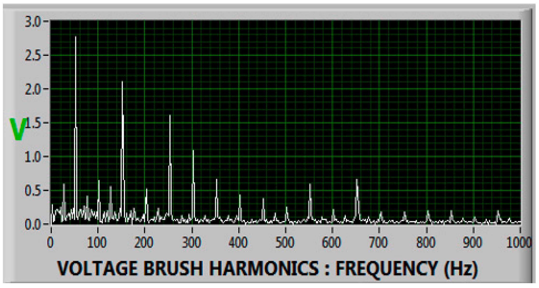
| 3rd, 5th, 7th harmonics | FFT | Static eccentricity | Magnetic asymmetry, rotor-stator misalignment | Odd multiples of 50/60 Hz | [8,72] |
| High-frequency spikes/bursts | Wavelet/Time domain | Electric Discharge Machining (EDM) | Oil film breakdown, excitation ripple discharge | >1 kHz transients | [1,10,11,12,43] |
| Sawtooth waveform | Time-domain/FFT | Homopolar voltage | Thyristor ripple, rotor magnetization | Fundamental + 150–300 Hz ripple | [4,12] |
| Random spike trains | Wavelet/Time domain | Electrostatic discharge (ESD) | Shaft charging/discharging events | Irregular transient bursts | [4,12,25,28] |
| Elevated neutral current amplitude | Current signature | Field winding asymmetry | Interturn shorts, excitation imbalance | Imbalance at stator frequency | [8,70] |
| Even-order harmonics (2nd, 4th) | FFT | Rotor winding faults | Asymmetric EMF from faulted coils | 100 Hz, 200 Hz in 50 Hz systems | [10,12] |
| Vibration sidebands | FFT/STFT | Bearing defects (outer/inner) | Mechanical resonance modulation from damaged elements | Mechanical modulating frequency | [64,66] |
| DC offset with ripple | Oscilloscope + FFT | Homopolar shaft voltage | Static excitation system asymmetry, field imbalance | DC + ripple voltage | [4,10,12,34] |
| Case Study/System | Mitigation Strategy | Reliability Metric | Improvement Observed | References |
|---|---|---|---|---|
| Multi-unit thermal plant (IRIS Power study) | Shaft condition monitoring (SCM) and grounding brushes | MTBF | Increased from 5.8 to 8.1 years (+39.6%) | [1] |
| 350 MW steam turbine generator | Silver-braid grounding retrofit | Bearing life expectancy | Increased from 3.5 to >7 years | [4] |
| Hydro-generator fleet (195 units) | Improved shaft insulation systems (Type 2) | Bearing insulation failure rate | Reduced by 56% over 15 years | [5] |
| Lab-scale 10 HP system | Conductive microfiber ring | Shaft voltage and bearing wear | Voltage < 2 V; bearing life doubled | [38] |
| Thermal generators (ABB/IRIS systems) | RARIC relay + shaft monitoring | MTBF and catastrophic failures | MTBF +30%; failures reduced by 50% | [43] |
| Fault Type/Cause | Typical Economic Impact (ZAR) | Mitigation Strategy | Economic Benefit/Cost Saving (ZAR) | References |
|---|---|---|---|---|
| Electrical Discharge Machining (EDM) of bearings | R555,000–R1,480,000 per unit failure (including downtime + replacements) | Shaft grounding rings/brushes | Up to R675,000 annual maintenance reduction per unit | [38,40,53] |
| Seal oil degradation due to shaft current | R185,000–R925,000 per event (seal repair + H2 loss + downtime) | Insulated bearings + microfiber grounding rings | Reduced H2 top-up and repair frequency; improved safety | [5,53] |
| Generator unplanned outage | R1.85 million–R9.25 million/day for 100–500 MW unit | Online monitoring + suppression systems | Increased MTBF (from 5.8 to 8.1 years); ROI within 1–2 outages | [1,7] |
| Shaft magnetization issues | R92,500–R277,500 (flange repair + rotor demagnetization and rebalancing) | Demagnetization + shaft voltage trending | Avoids rotor dismantling; improves predictive maintenance scheduling | [30,60] |
| VFD/Static Exciter transient discharge | >R462,500 per failure (excitation system + sensor damage + unscheduled repair) | High-frequency filtering + gold-bristle brushes | Significant reduction in equipment burnout; improved system reliability | [10,11,50] |
| Fleet-level degradation over time | Multimillion-Rand bearing and stator core damage across large fleets (e.g., Eskom or SAPP fleets) | Hybrid grounding + insulation systems | R54 million in bearing damage avoided over 15 years in 195-unit hydro fleet | [5,9] |
Disclaimer/Publisher’s Note: The statements, opinions and data contained in all publications are solely those of the individual author(s) and contributor(s) and not of MDPI and/or the editor(s). MDPI and/or the editor(s) disclaim responsibility for any injury to people or property resulting from any ideas, methods, instructions or products referred to in the content. |
© 2025 by the authors. Licensee MDPI, Basel, Switzerland. This article is an open access article distributed under the terms and conditions of the Creative Commons Attribution (CC BY) license (https://creativecommons.org/licenses/by/4.0/).
Share and Cite
Mailula, K.O.; Saha, A.K. A Comprehensive Review of Shaft Voltages and Bearing Currents, Measurements and Monitoring Systems in Large Turbogenerators. Energies 2025, 18, 2067. https://doi.org/10.3390/en18082067
Mailula KO, Saha AK. A Comprehensive Review of Shaft Voltages and Bearing Currents, Measurements and Monitoring Systems in Large Turbogenerators. Energies. 2025; 18(8):2067. https://doi.org/10.3390/en18082067
Chicago/Turabian StyleMailula, Katudi Oupa, and Akshay K. Saha. 2025. "A Comprehensive Review of Shaft Voltages and Bearing Currents, Measurements and Monitoring Systems in Large Turbogenerators" Energies 18, no. 8: 2067. https://doi.org/10.3390/en18082067
APA StyleMailula, K. O., & Saha, A. K. (2025). A Comprehensive Review of Shaft Voltages and Bearing Currents, Measurements and Monitoring Systems in Large Turbogenerators. Energies, 18(8), 2067. https://doi.org/10.3390/en18082067