
Sliding Wear Performance of AlCrN Coating on TiB2/Ti Composites at High Temperatures

 ,
, 
 ,
,  ,
,  and
and 
Abstract
:1. Introduction
2. Materials and Methods
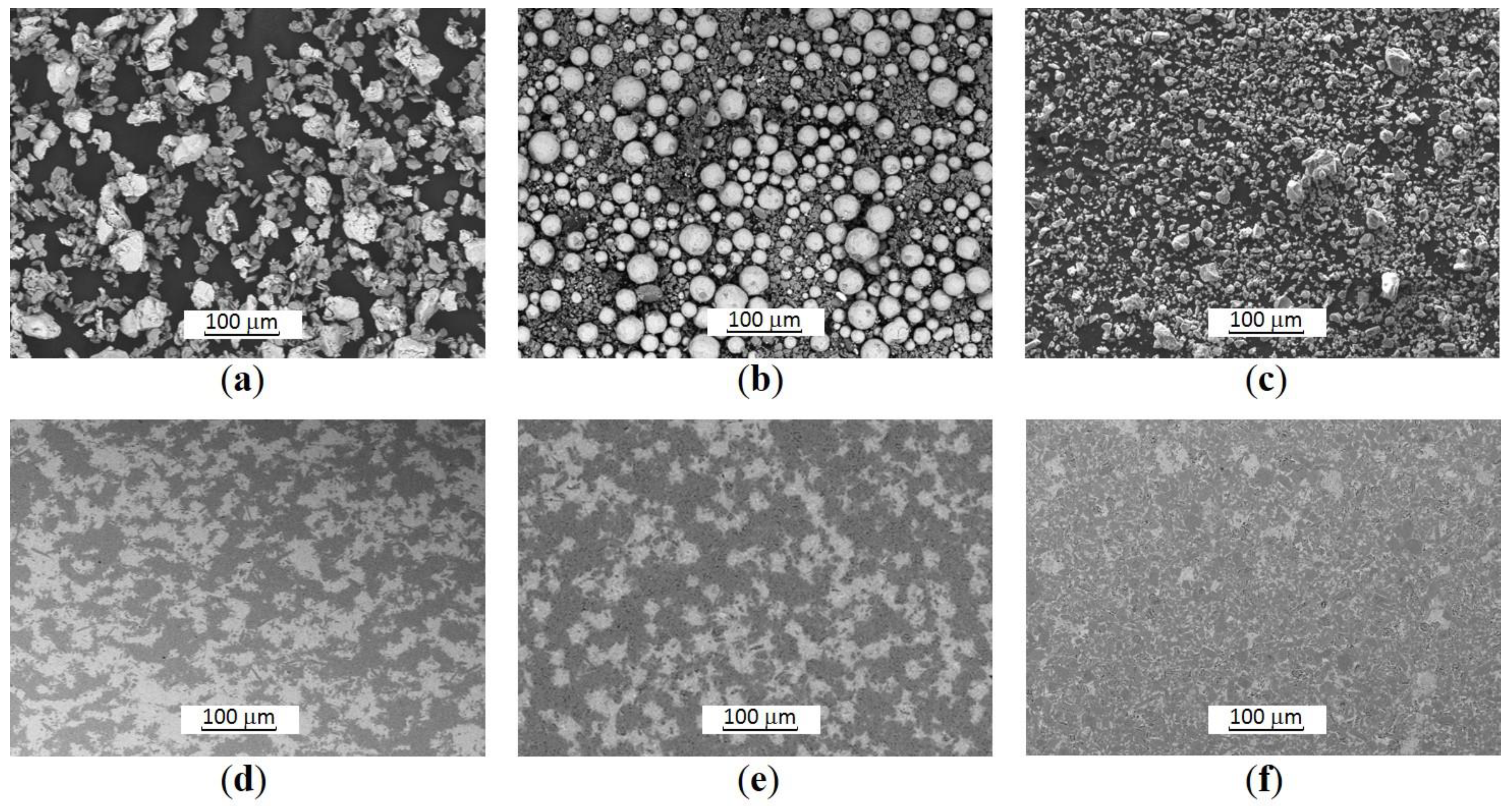
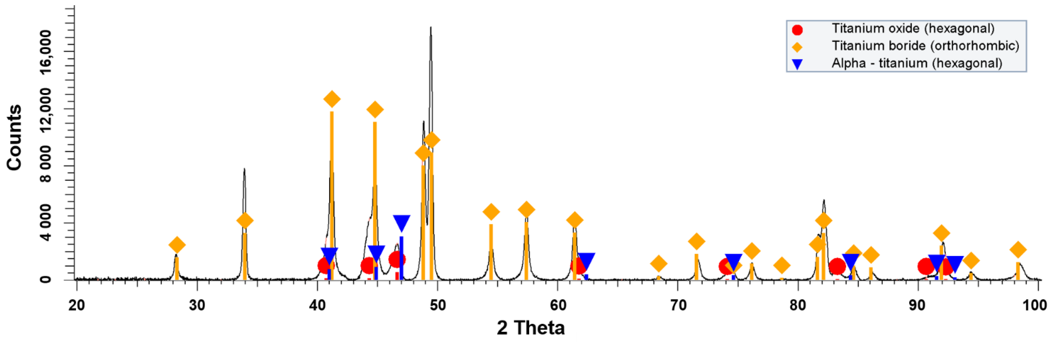
2.1. TiB2/Ti Composites
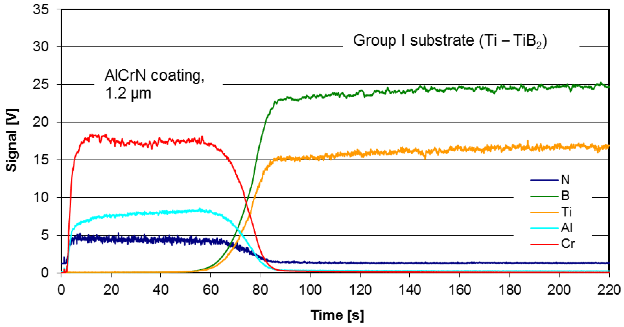
2.2. AlCrN Coating
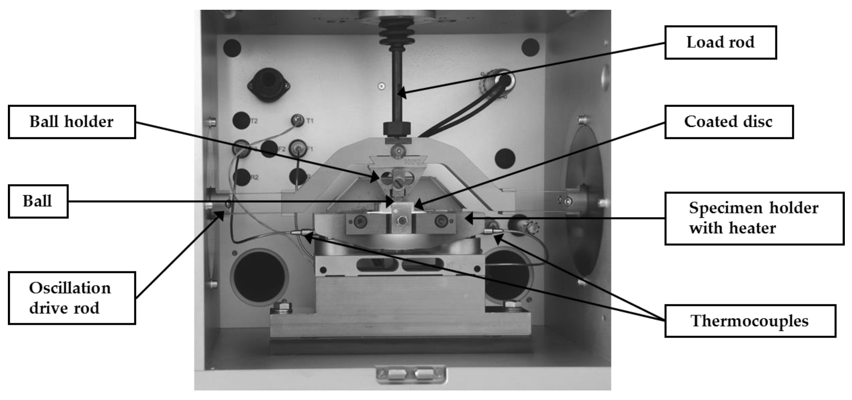
2.3. Wear Tests
3. Results and Discussion
4. Conclusions
- The conducted research on ceramic-based discs of Ti/TiB2 has demonstrated that the selection of input powder mixtures and methods of their consolidation are the important issues to be taken into consideration for successful design of PVD coatings intended for high-temperature applications.
- The composites were manufactured by spark plasma sintering (SPS) from three variants of powders mixtures: Ti with TiB2, Ti6Al4V with TiB2 as well as Ti with B, using (five) different sintering temperatures. The composites made of Ti6Al4V-TiB2 require further optimization to reach the level of porosity and homogeneity adequate for proper finishing of the surface, which is crucial for coating deposition and the assessment of adhesion and wear resistance. The composites made of powders mixtures: Ti with TiB2, as well as Ti and B with different sintering temperatures are suitable for obtaining sufficient surface finish and to be coated in PVD process.
- The coating adhesion, measured using critical loads, obtained for the coating deposited on the surface of composites, depend on sintering temperature. The highest values of critical loads were obtained for the coated samples fabricated from the powder mixture prepared of the pure titanium and titanium diboride raw powders (Ti-TiB2). The first brittle cracks were found at loads a bit above 30 N, the partial delamination in the range of 36–40 N, and exposure of the substrate (total removal of the coating) at loads slightly above 75 N.
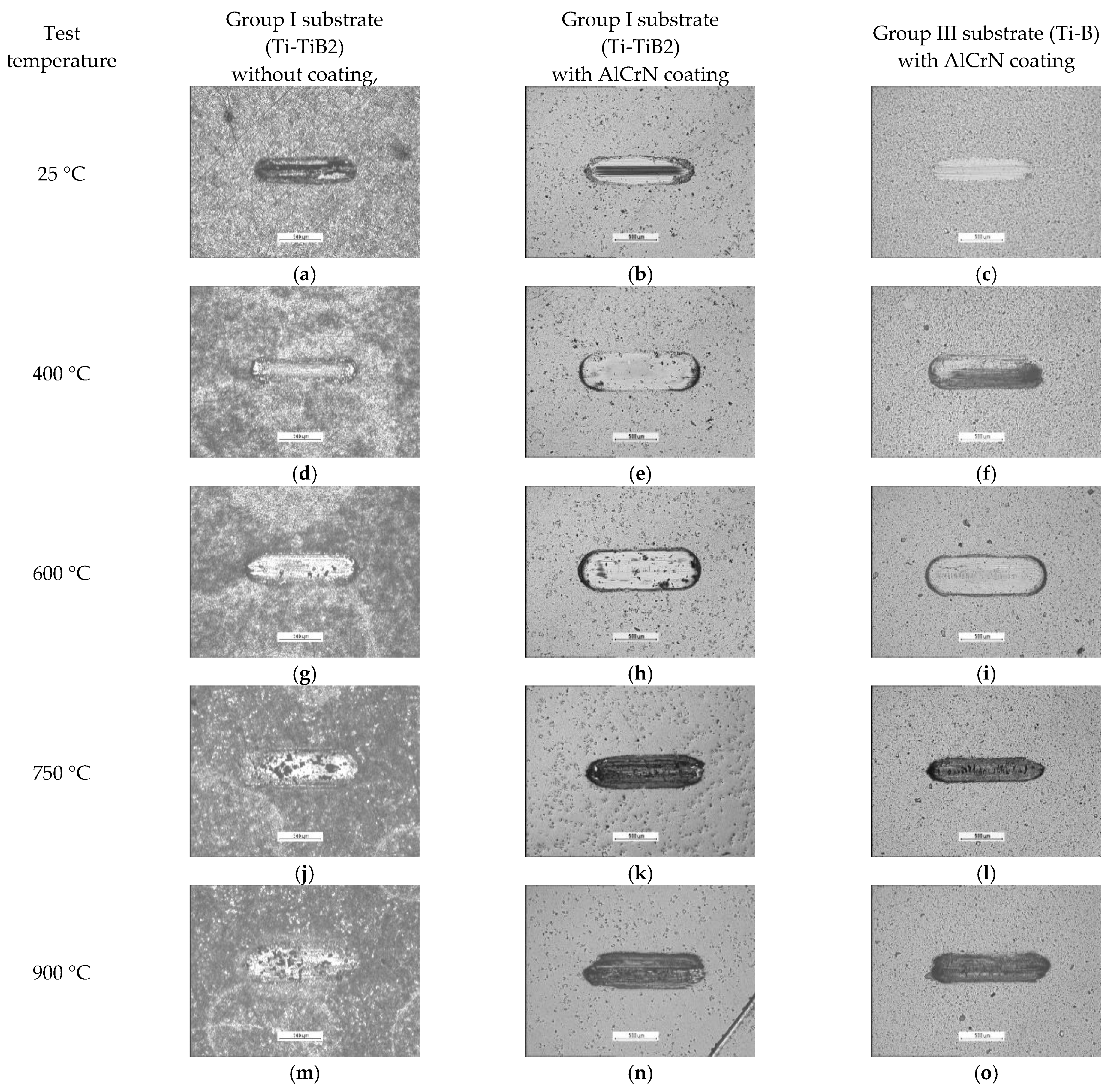
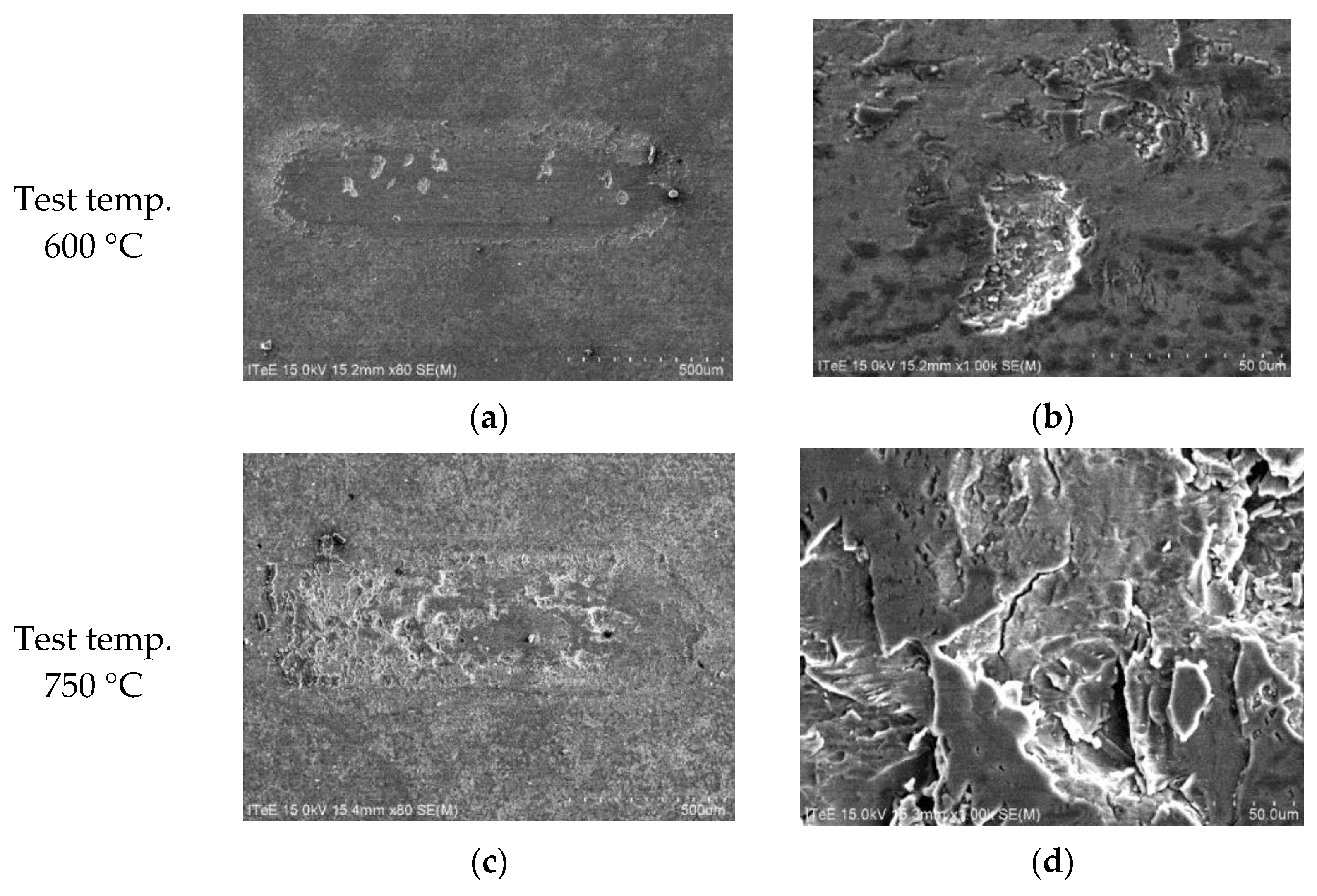
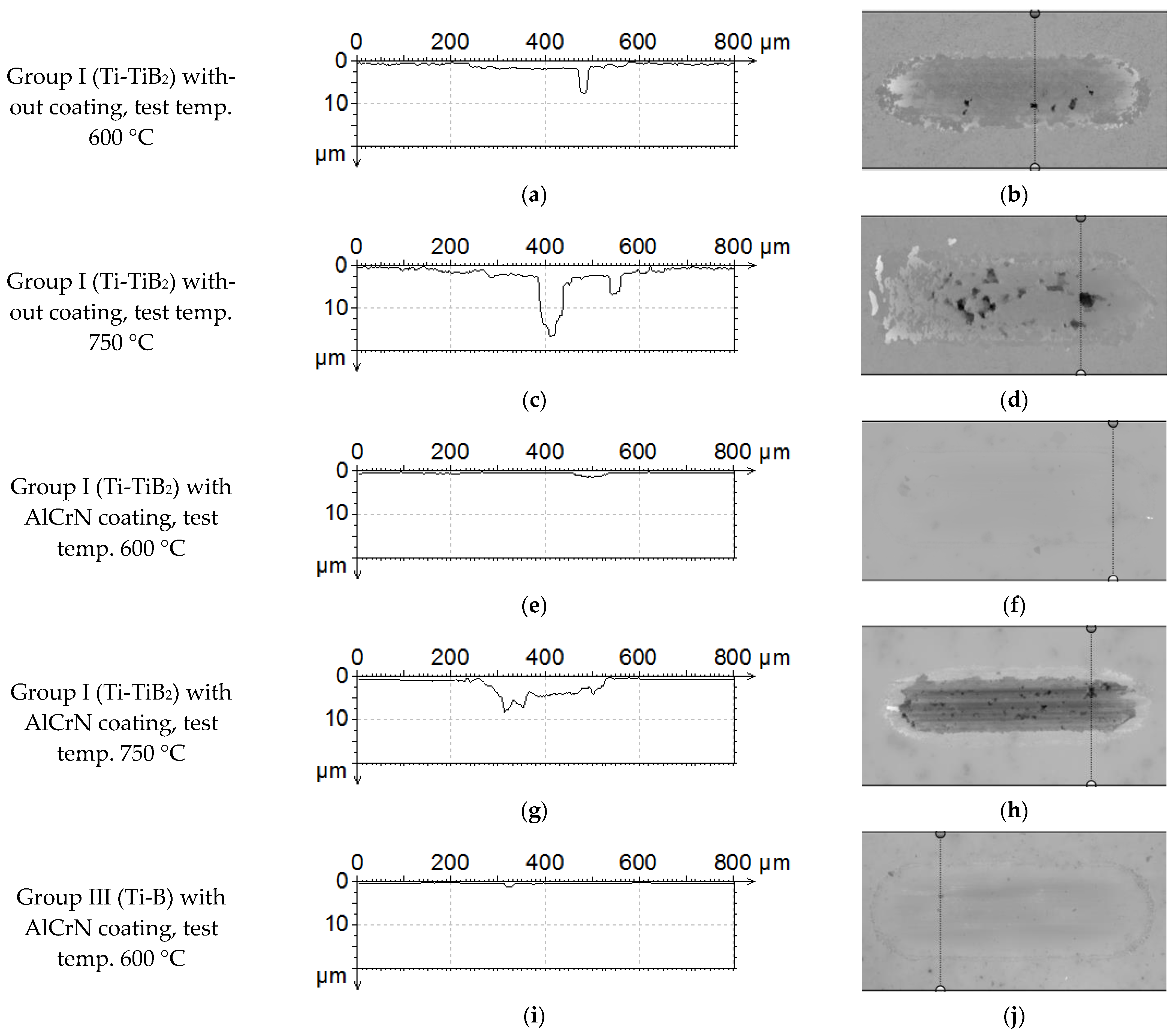
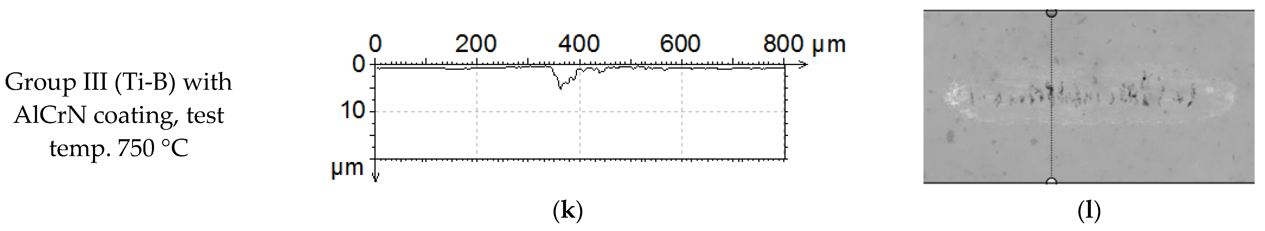
- The volumetric wear of the uncoated composites is found to be stable up to 400 °C, but further temperature rise, leads to two-fold increase in volumetric wear at 600 °C and 7-fold and 10-fold at 750 °C and 900 °C, respectively.
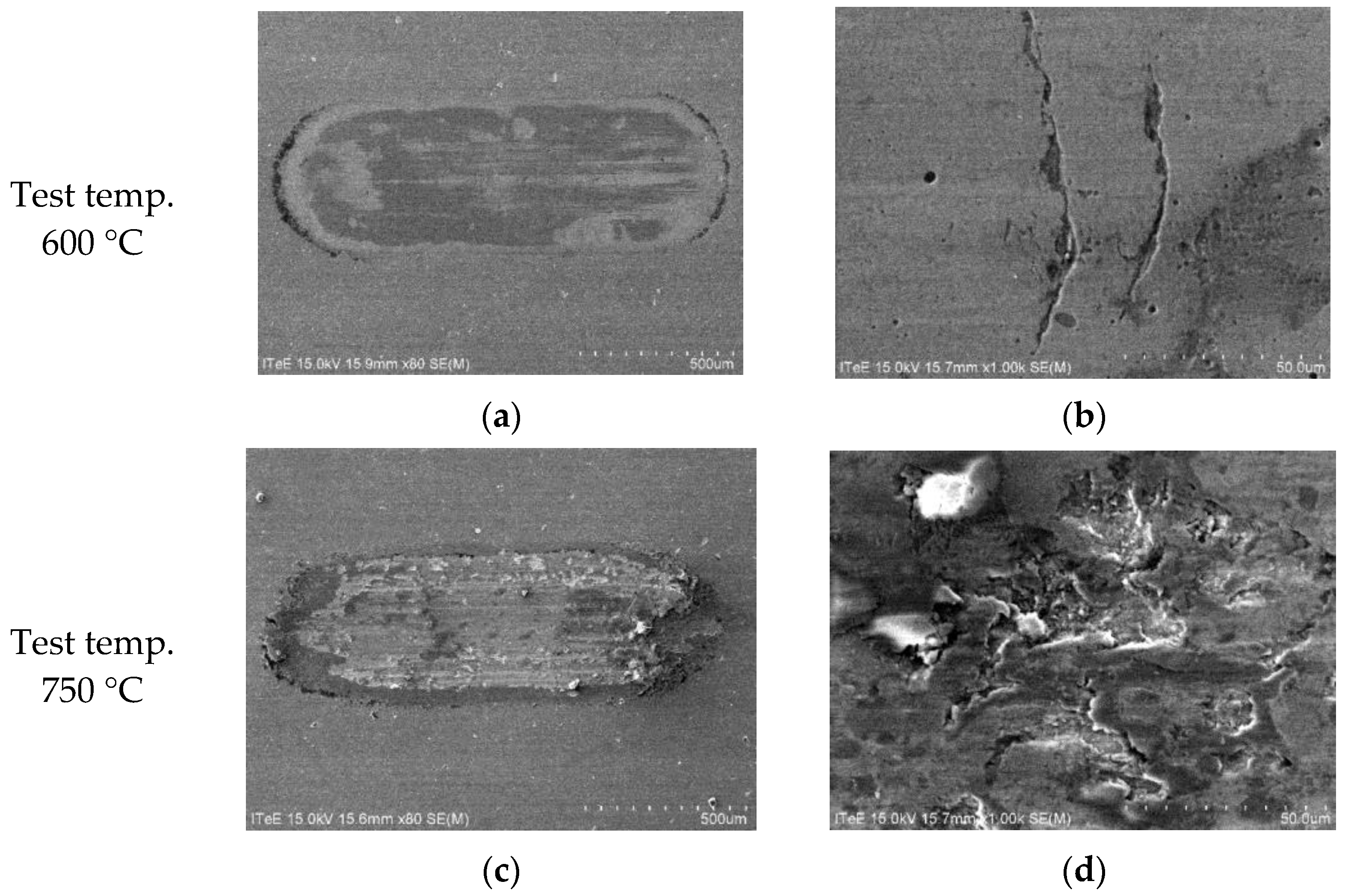
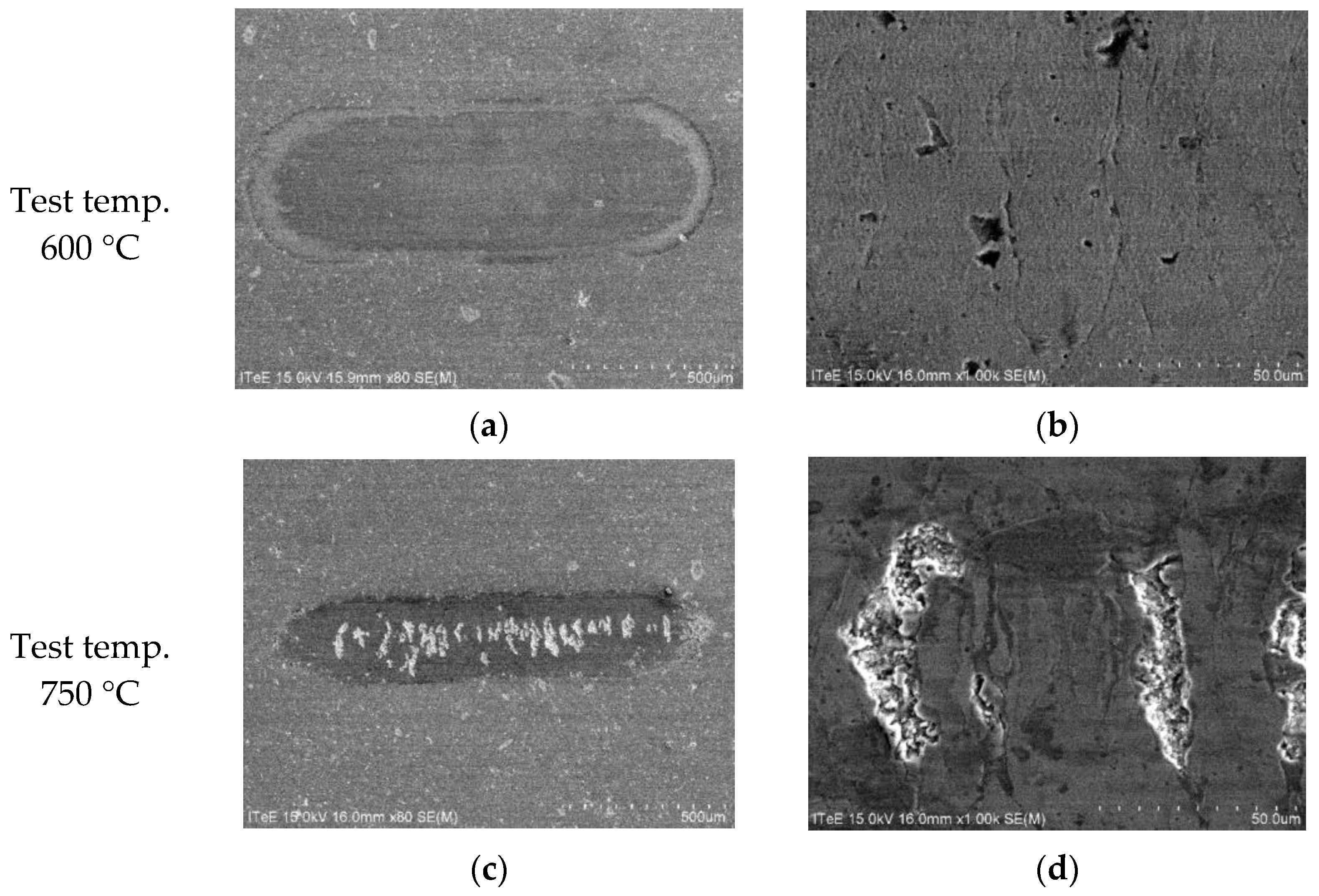
- The AlCrN coating can provide protection of the composites against the wear in the wide range of temperatures (from room temperature up to 900 °C).
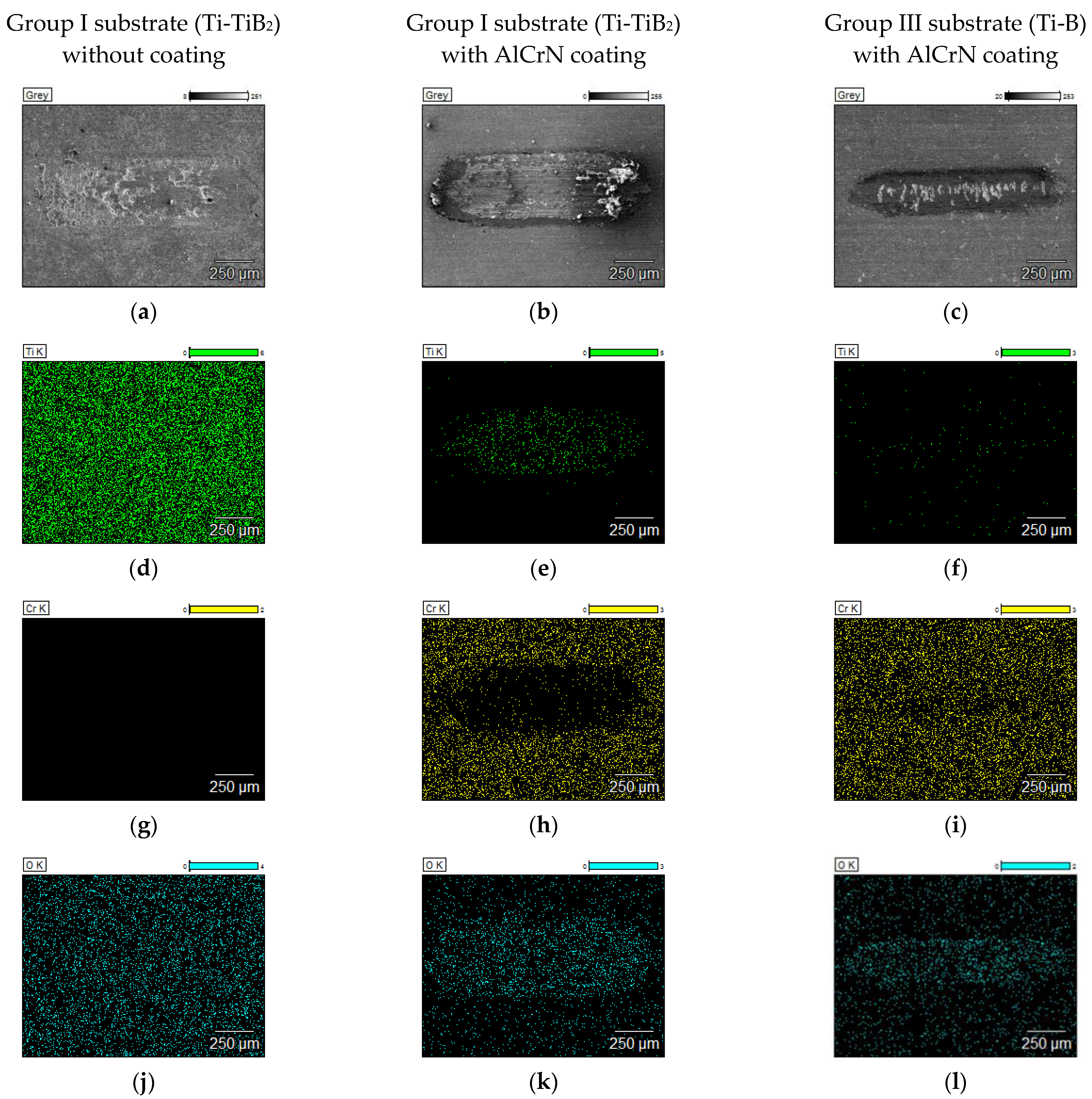
- In the case of uncoated composite, two processes play a major role during wear: cracking propagation and surface oxidation. Both processes are temperature dependent. The presence of AlCrN coating on the composite surface protects the surface against deep cracking and surface oxidation.
- The composites of Group I, from a mixture of pure Ti and TiB2 as well as Group III from a mixture of pure Ti and B allow to the achievement of a satisfactory surface quality, high adhesion of the PVD coating and moderate wear at high temperatures. However, the composite made of pure Ti and B seems to be better solution for temperatures exceeding 600 °C.
Author Contributions
Funding
Institutional Review Board Statement
Informed Consent Statement
Data Availability Statement
Conflicts of Interest
References
- Varga, M.; Leroch, S.; Eder, S.J.; Rojacz, H.; Ripoll, M.R. Influence of velocity on high-temperature fundamental abrasive contact: A numerical and experimental approach. Wear 2019, 426–427, 370–377. [Google Scholar] [CrossRef]
- Torres, H.; Ripoll, M.R.; Prakash, B. Tribological behaviour of self-lubricating materials at high temperatures. Int. Mater. Rev. 2018, 63, 309–340. [Google Scholar] [CrossRef]
- Torres, H.; Slawik, S.; Gachot, C.; Prakash, B.; Ripoll, M.R. Microstructural design of self-lubricating laser claddings for use in high temperature sliding applications. Surf. Coat. Technol. 2018, 337, 24–34. [Google Scholar] [CrossRef]
- Liu, L.; Minasyan, T.; Ivanov, R.; Aydinyan, S.; Hussainova, I. Selective laser melting of TiB2-Ti composite with high content of ceramic phase. Ceram. Int. 2020, 46, 21128–21135. [Google Scholar] [CrossRef]
- Liu, L.; Aydinyan, S.; Minasyan, T.; Hussainova, I. SHS Produced TiB2-Si Powders for Selective Laser Melting of Ceramic-Based Composite. Appl. Sci. 2020, 10, 3283. [Google Scholar] [CrossRef]
- Kumar, C.; Das, M.; Paul, C.; Bindra, K. Comparison of bead shape, microstructure and mechanical properties of fiber laser beam welding of 2 mm thick plates of Ti-6Al-4V alloy. Opt. Laser Technol. 2018, 105, 302–361. [Google Scholar] [CrossRef]
- Zhang, Q.; Zhou, Y.; Wang, L.; Cui, X.; Wang, S. Investigation on tribo-layers and their function of a titanium alloy during dry sliding. Tribol. Int. 2016, 94, 541–549. [Google Scholar] [CrossRef]
- Umanskyi, O.; Storozhenko, M.; Hussainova, I.; Terentjev, O.; Kovalchenko, A.; Antonov, M. Effect of TiB2 Additives on Wear Behavior of NiCrBSi-Based Plasma-Sprayed Coatings. Mater. Sci. 2016, 22, 15–19. [Google Scholar] [CrossRef] [Green Version]
- Basu, B.; Raju, G.B.; Suri, A.K. Processing and properties of monolithic TiB2 based materials. Int. Mater. Rev. 2006, 51, 352–374. [Google Scholar] [CrossRef]
- Zhang, Z.; Dong, H. A State-of-the-art overview. Recent development in low friction and wear-resistant coatings and surfaces for high-temperature forming tools. Manuf. Rev. 2014, 1, 24. [Google Scholar] [CrossRef] [Green Version]
- Wu, L.; Qiu, L.; Du, Y.; Zeng, F.; Lu, Q.; Tan, Z.; Yin, L.; Chen, L.; Zhu, J. Structure and Mechanical Properties of PVD and CVD TiAlSiN Coatings Deposited on Cemented Carbide. Crystals 2021, 11, 598. [Google Scholar] [CrossRef]
- Moghaddam, P.V.; Prakash, B.; Vuorinen, E.; Fallqvist, M.; Andersson, J.M.; Hardell, J. High temperature tribology of TiAlN PVD coating sliding against 316L stainless steel and carbide-free bainitic steel. Tribol. Int. 2021, 159, 106847. [Google Scholar] [CrossRef]
- Scheerer, H.; Berger, C. Wear Mechanisms of (Cr,Al,Y)N PVD Coatings at Elevated Temperatures. Plasma Process. Polym. 2009, 6, S157–S161. [Google Scholar] [CrossRef]
- Žemlička, R.; Alishahi, M.; Jílek, M.; Souček, P.; Daniel, J.; Kluson, J.; Bolvardi, H.; Lümkemann, A.; Vašina, P. Enhancing mechanical properties and cutting performance of industrially sputtered AlCrN coatings by inducing cathodic arc glow discharge. Surf. Coat. Technol. 2021, 422, 127563. [Google Scholar] [CrossRef]
- Mayrhofer, P.; Music, D.; Reeswinkel, T.; Fuß, H.-G.; Schneider, J. Structure, elastic properties and phase stability of Cr1−xAlxN. Acta Mater. 2008, 56, 2469–2475. [Google Scholar] [CrossRef]
- Souza, P.S.; Santos, A.J.; Cotrim, M.A.; Abrao, A.; Câmara, M.A. Analysis of the surface energy interactions in the tribological behavior of ALCrN and TIAlN coatings. Tribol. Int. 2020, 146, 106206. [Google Scholar] [CrossRef]
- Tang, J.-F.; Lin, C.-Y.; Yang, F.-C.; Chang, C.-L. Influence of Nitrogen Content and Bias Voltage on Residual Stress and the Tribological and Mechanical Properties of CrAlN Films. Coatings 2020, 10, 546. [Google Scholar] [CrossRef]
- Michalczewski, R.; Kalbarczyk, M.; Piekoszewski, W.; Szczerek, M.; Tuszyński, W. The rolling contact fatigue of WC/C-coated spur gears. Proc. Inst. Mech. Eng. Part J J. Eng. Tribol. 2013, 227, 850–860. [Google Scholar] [CrossRef]
- Michalczewski, R.; Kalbarczyk, M.; Mańkowska-Snopczyńska, A.; Osuch-Słomka, E.; Piekoszewski, W.; Snarski-Adamski, A.; Szczerek, M.; Tuszyński, W.; Wulczyński, J.; Wieczorek, A. The Effect of a Gear Oil on Abrasion, Scuffing, and Pitting of the DLC-Coated 18CrNiMo7-6 Steel. Coatings 2018, 9, 2. [Google Scholar] [CrossRef] [Green Version]
- Tuszynski, W.; Kalbarczyk, M.; Michalak, M.; Michalczewski, R.; Wieczorek, A. The Effect of WC/C Coating on the Wear of Bevel Gears Used in Coal Mines. Mater. Sci. 2015, 21, 358–363. [Google Scholar] [CrossRef] [Green Version]
- Michalak, M.; Michalczewski, R.; Wulczyński, J.; Szczerek, M. The method of tribotesting of PVD coated elements in oscillatory motion at high temperatures. Tribologia 2015, 259, 77–94. [Google Scholar]
- Antonov, M.; Hussainova, I.; Sergejev, F.; Kulu, P.; Gregor, A. Assessment of gradient and nanogradient PVD coatings behaviour under erosive, abrasive and impact wear conditions. Wear 2009, 267, 898–906. [Google Scholar] [CrossRef]
- Madej, M.; Ozimina, D.; Kurzydlowski, K.; Płociński, T.; Wieciński, P.; Styp-Rekowski, M.; Matuszewski, M. Properties of diamond-like carbon coatings deposited on CoCrMo alloys. Trans. FAMENA 2015, 39, 79–88. [Google Scholar]
- Michalczewski, R.; Kalbarczyk, M.; Slomka, Z.; Hussainova, I.; Liu, L.; Antonov, M. Adhesion of AlCrN coating deposited on TiB2/Ti composites sintered by SPS dedicated for high temperature tribological applications. IOP Conf. Ser. Mater. Sci. Eng. 2021, 1140, 012010. [Google Scholar] [CrossRef]
- Namini, A.S.; Dilawary, S.A.A.; Motallebzadeh, A.; Asl, M.S. Effect of TiB2 addition on the elevated temperature tribological behavior of spark plasma sintered Ti matrix composite. Compos. Part B Eng. 2019, 172, 271–280. [Google Scholar] [CrossRef]
- Kumar, R.; Liu, L.; Antonov, M.; Ivanov, R.; Hussainova, I. Hot Sliding Wear of 88 wt.% TiB–Ti Composite from SHS Produced Powders. Materials 2021, 14, 1242. [Google Scholar] [CrossRef]
- Kumar, R.; Antonov, M.; Liu, L.; Hussainova, I. Sliding wear performance of in-situ Spark Plasma Sintered Ti-TiB2 composites at temperatures up to 900 °C. Wear 2021, 476, 203663. [Google Scholar] [CrossRef]
- Michalak, M.; Michalczewski, R.; Osuch-Słomka, E.; Maldonado-Cortés, D.; Szczerek, M. The Effect of Temperature on Wear Mechanism of the AlCrN Coated Components. Key Eng. Mater. 2016, 674, 233–238. [Google Scholar] [CrossRef]
- Michalczewski, R.; Kalbarczyk, M.; Maldonado-Cortés, D. The method of tribotesting of PVD coated elements in oscillation motion at high temperature. IOP Conf. Ser. Mater. Sci. Eng. 2021, 1140, 012024. [Google Scholar] [CrossRef]
- Barshilia, H.C.; Prakash, M.S.; Jain, A.; Rajam, K. Structure, hardness and thermal stability of TiAlN and nanolayered TiAlN/CrN multilayer films. Vacuum 2005, 77, 169–179. [Google Scholar] [CrossRef]


| Name | Temp. | Ra | HRC |
|---|---|---|---|
| [°C] | [µm] | - | |
| Group I (Ti-TiB2) | 1250 | 0.091 ± 0.008 | 76 ± 2 |
| 1450 | 0.067 ± 0.007 | 77 ± 1 | |
| Group II (Ti6Al4V-TiB2) | 1050 | 1.599 ± 0.200 | 58 ± 9 |
| 1150 | 0.853 ± 0.080 | 70 ± 2 | |
| 1250 | 0.461 ± 0.005 | 75 ± 2 | |
| Group III (Ti-B) | 1050 | 0.034 ± 0.004 | 79 ± 1 |
| 1150 | 0.036 ± 0.005 | 80 ± 1 | |
| 1350 | 0.044 ± 0.004 | 79 ± 1 |
| Name | Temp. | LC1 | LC2 | LC3 |
|---|---|---|---|---|
| [°C] | [N] | [N] | [N] | |
| Group I (Ti-TiB2) | 1250 | 28.0 | 38.5 | 77.8 |
| 1450 | 36.9 | 38.9 | 75.4 | |
| Group II (Ti6Al4V-TiB2) | 1050 | not measurable | not measurable | not measurable |
| 1150 | not measurable | not measurable | not measurable | |
| 1250 | not measurable | not measurable | not measurable | |
| Group III (Ti-B) | 1050 | 15.0 | 38.0 | 61.7 |
| 1150 | 14.2 | 33.8 | 71.2 | |
| 1350 | 16.0 | 36.1 | 66.4 |
Publisher’s Note: MDPI stays neutral with regard to jurisdictional claims in published maps and institutional affiliations. |
© 2021 by the authors. Licensee MDPI, Basel, Switzerland. This article is an open access article distributed under the terms and conditions of the Creative Commons Attribution (CC BY) license (https://creativecommons.org/licenses/by/4.0/).
Share and Cite
Michalczewski, R.; Kalbarczyk, M.; Słomka, Z.; Osuch-Słomka, E.; Łuszcz, M.; Liu, L.; Antonov, M.; Hussainova, I. Sliding Wear Performance of AlCrN Coating on TiB2/Ti Composites at High Temperatures. Materials 2021, 14, 6771. https://doi.org/10.3390/ma14226771
Michalczewski R, Kalbarczyk M, Słomka Z, Osuch-Słomka E, Łuszcz M, Liu L, Antonov M, Hussainova I. Sliding Wear Performance of AlCrN Coating on TiB2/Ti Composites at High Temperatures. Materials. 2021; 14(22):6771. https://doi.org/10.3390/ma14226771
Chicago/Turabian StyleMichalczewski, Remigiusz, Marek Kalbarczyk, Zbigniew Słomka, Edyta Osuch-Słomka, Maciej Łuszcz, Le Liu, Maksim Antonov, and Irina Hussainova. 2021. "Sliding Wear Performance of AlCrN Coating on TiB2/Ti Composites at High Temperatures" Materials 14, no. 22: 6771. https://doi.org/10.3390/ma14226771
APA StyleMichalczewski, R., Kalbarczyk, M., Słomka, Z., Osuch-Słomka, E., Łuszcz, M., Liu, L., Antonov, M., & Hussainova, I. (2021). Sliding Wear Performance of AlCrN Coating on TiB2/Ti Composites at High Temperatures. Materials, 14(22), 6771. https://doi.org/10.3390/ma14226771