
Design and Fabrication of Extremely Lightweight Truss-Structured Metal Mirrors

 ,
,
Abstract
:1. Introduction
2. Design of the Truss-Structured Mirrors
2.1. Truss Cell
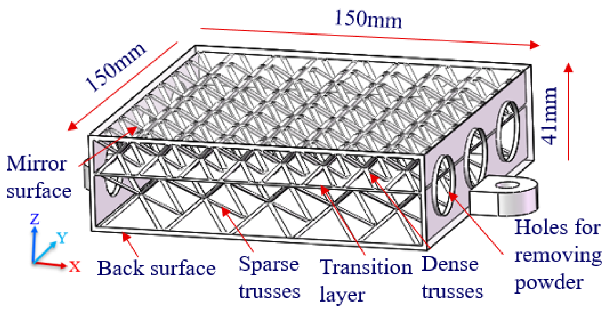
2.2. Truss Mirrors
2.3. FEA Verifications
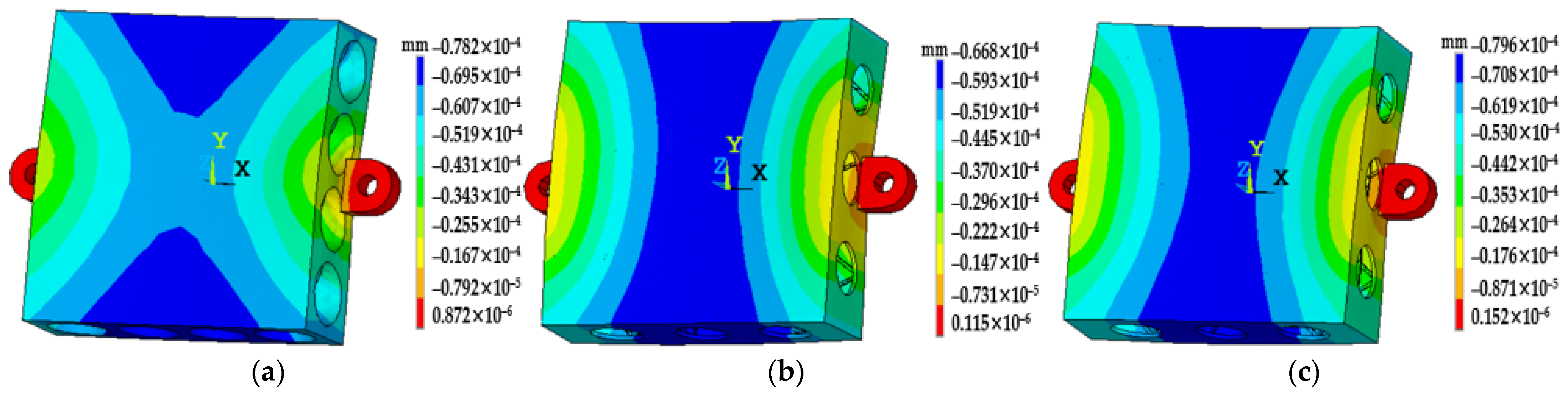
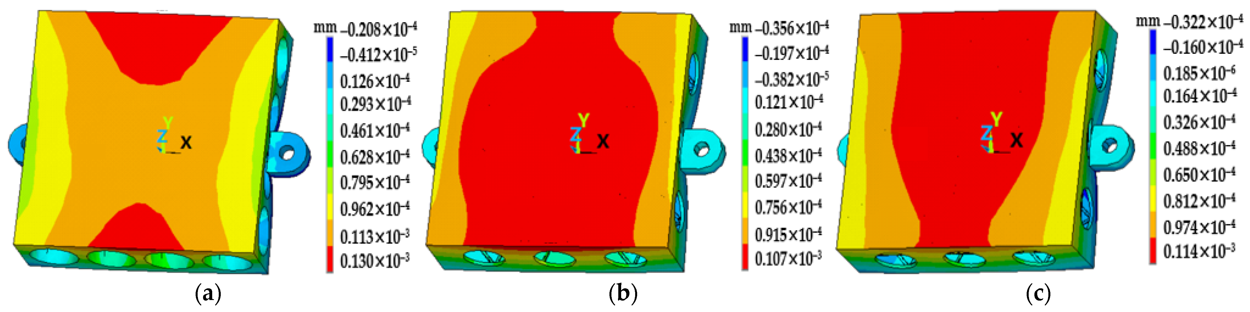
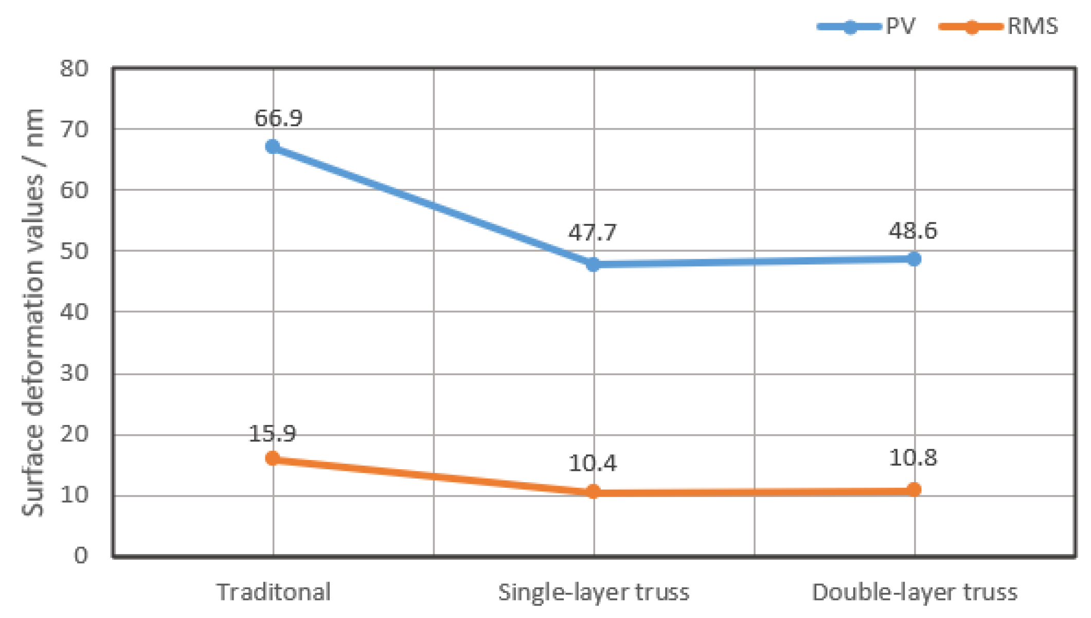
2.3.1. Surface Shape Deformation
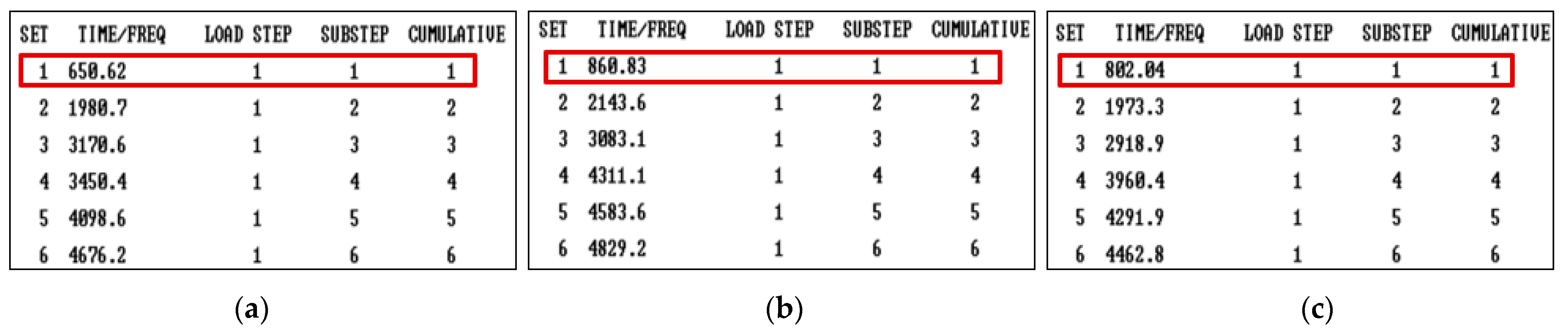
2.3.2. Modal Analysis
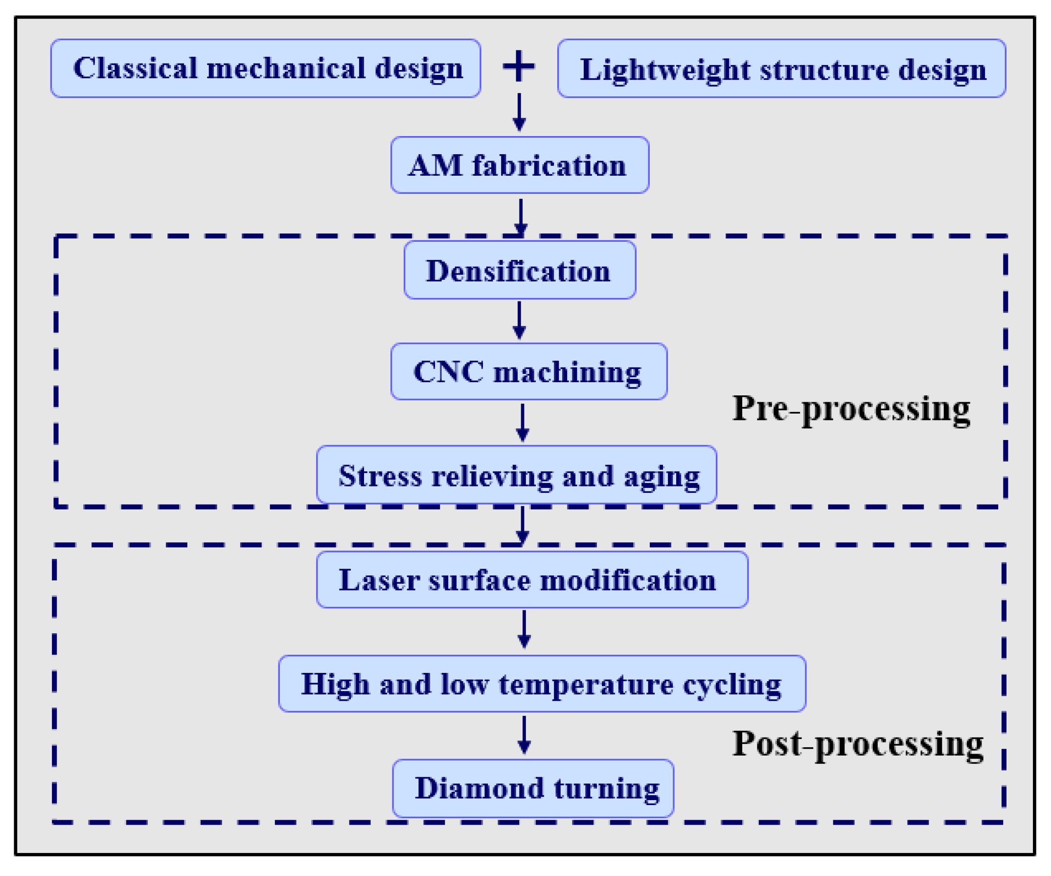
3. Fabrication of Truss-Structured Mirrors
3.1. Mirror Blanks Fabrication
3.2. Preprocessing for Mirror Blank Stabilization
3.3. Postprocessing for Surface Modification
3.4. Finish Machining of Mirror Surfaces
4. Conclusions
- Truss-structured mirrors show a better structural stability than that of conventional mirrors;
- A very high weight reduction of up to 85% with nearly the same stiffness as traditional mirrors could be obtained;
- By hot isostatic pressing, the porosity of AM mirror blanks was reduced. Through the aging treatment, the residual stress in the mirror blank after semi-finish machining was also eliminated;
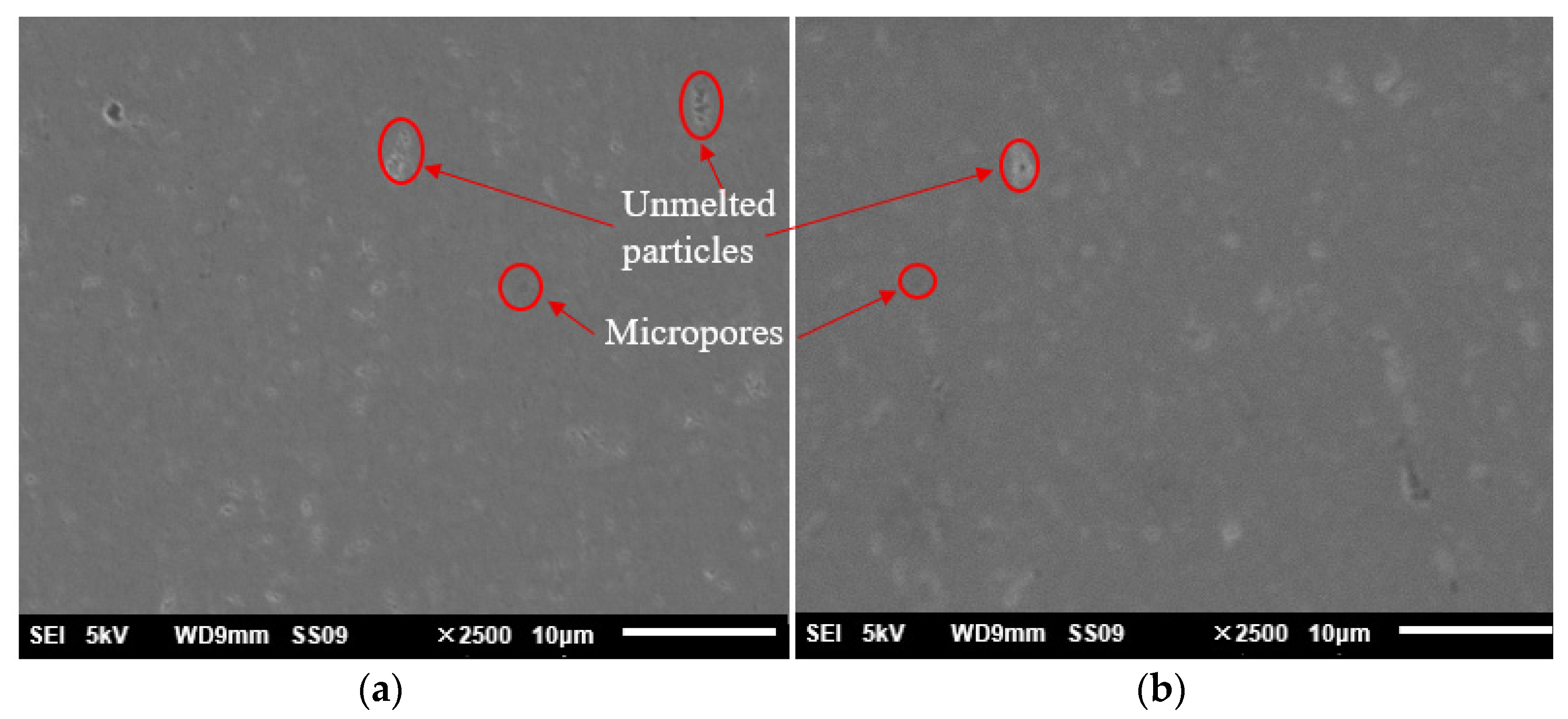
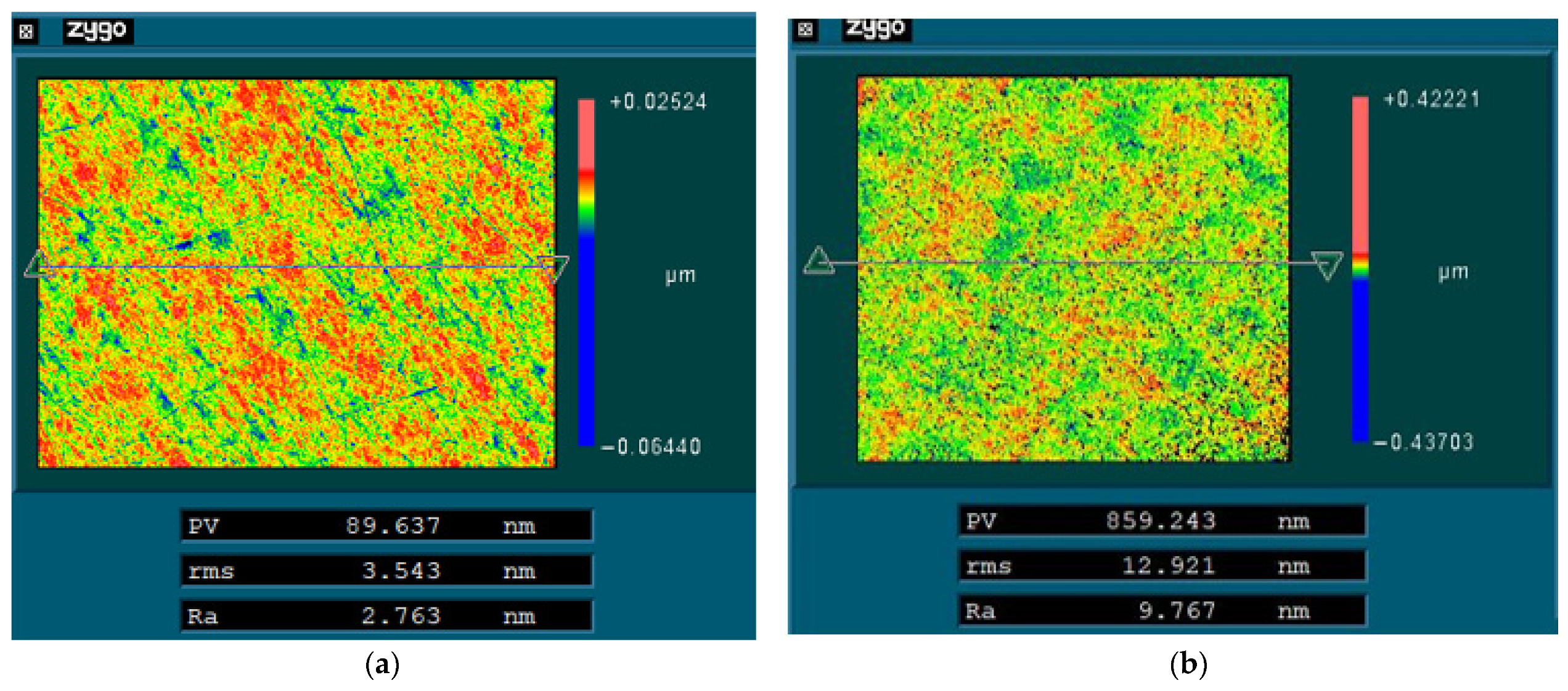
- After laser modification, the mirror surface had a uniform metallographic structure without obvious unmolten particles and microscopic pores.
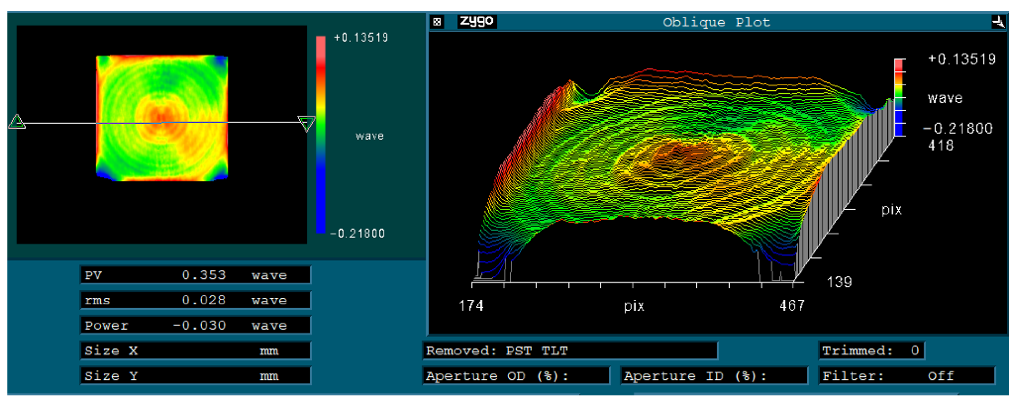
- After finishing, the surface shape accuracy was 0.353 λ (PV) and 0.028 λ (RMS) (λ = 632.8 nm). The surface roughness (Ra) of the mirrors was better than 3 nm for a bare metal mirror without NiP coating.
- The truss-structured mirrors had strong temperature stability, due to the complete elimination of the bimetallic effect.
Author Contributions
Funding
Institutional Review Board Statement
Informed Consent Statement
Data Availability Statement
Acknowledgments
Conflicts of Interest
References
- Gardner, J.P.; Mather, J.C.; Clampin, M.; Doyon, R.; Greenhouse, M.A.; Hammel, H.B.; Wright, G.S. The james webb space telescope. Space Sci. Rev. 2006, 123, 485–606. [Google Scholar] [CrossRef] [Green Version]
- Hilpert, E.; Hartung, J.; Risse, S.; Eberhardt, R.; Tünnermann, A. Precision manufacturing of a lightweight mirror body made by selective laser melting. Precis. Eng. 2018, 53, 310–317. [Google Scholar] [CrossRef] [Green Version]
- Atkins, C.; Brzozowski, W.; Dobson, N.; Milanova, M.; Todd, S.; Pearson, D.; Nistea, I.T. Additively manufactured mirrors for CubeSats. Proc. SPIE 2019, 11116, 1111616. [Google Scholar]
- Azam, F.I.; Rani, A.M.A.; Altaf, K.; Rao, T.V.V.L.N.; Zaharin, H.A. An in-depth review on direct additive manufacturing of metals. IOP Publ. 2018, 328, 012005. [Google Scholar] [CrossRef]
- Bai, Y.; Shi, Z.; Yan, J.L.; Wang, H. Optical surface generation on additively manufactured AlSiMg0.75 alloys with ultrasonic vibration-assisted machining. J. Mater. Process. Technol. 2020, 280, 116597. [Google Scholar] [CrossRef]
- Heidler, N.; Hilpert, E.; Hartung, J.; Von Lukowicz, H.; Damm, C.; Peschel, T.; Risse, S. Additive manufacturing of metal mirrors for TMA telescope. Proc. SPIE 2018, 10692, 106920C. [Google Scholar]
- Yin, G.; Ding, F.; Wang, H.; Bai, Y.; Liu, X. Connection performance in steel–concrete composite truss bridge structures. J. Bridge Eng. 2017, 22, 04016126. [Google Scholar] [CrossRef]
- Glassman, T.; Levi, J.; Liepmann, T.; Hahn, W.; Bisson, G.; Porpora, D.; Hadjimichael, T. Alignment of the James Webb Space Telescope optical telescope element. Proc. SPIE 2016, 9904, 99043Z. [Google Scholar]
- Craig, U. Autonomous Assembly of a Reconfiguarble Space Telescope (AAReST)-A CubeSat/Microsatellite based technology demonstrator. In Proceedings of the 27th Annual AIAA/USU Conference on Small Satellites, Utah State University, Logan, UT, USA, 12–15 August 2013; pp. 1–7. [Google Scholar]
- Valente, T.M.; Vukobratovich, D. A Comparison of the merits of open-back, symmetric sandwich, and contoured back mir-rors as light-weighted optics. In Proceedings of the 33rd Annual Technical Symposium: Precision Engineering and Optomechanics, San Diego, CA, USA, 7–11 August 1989; pp. 20–36. [Google Scholar]
- Hu, H.; Guan, Y.; Zhao, S.; Zheng, L. Analysis led design and optimization for large aperture mirror. J. Syst. Simula-Tion 2013, 25, 990–994. [Google Scholar]
- Gussev, M.N.; Sridharan, N.; Thompson, Z.; Terrani, K.A.; Babu, S.S. Influence of hot isostatic pressing on the performance of aluminum alloy fabricated by ultrasonic additive manufacturing. Scr. Mater. 2018, 145, 33–36. [Google Scholar] [CrossRef]
- Pan, W.; Ye, Z.; Zhang, Y.; Liu, Y.; Liang, B.; Zhai, Z. Research on microstructure and properties of AlSi10Mg fabricated by selective laser melting. Materials 2022, 15, 2528. [Google Scholar] [CrossRef] [PubMed]
- Zhang, H.; Wang, Y.; Wang, J.J.; Ni, D.R.; Wang, D.; Xiao, B.L.; Ma, Z.Y. Achieving superior mechanical properties of selective laser melted AlSi10Mg via direct aging treatment. J. Mater. Sci. Technol. 2022, 108, 226–235. [Google Scholar] [CrossRef]
- Khaimovich, A.; Erisov, Y.; Shishkovsky, I. Thermodynamic Conditions for Consolidation of Dissimilar Materials in Bimetal and Functional Graded Structures. Materials 2022, 15, 825. [Google Scholar] [CrossRef] [PubMed]
- Ren, Y.; Zhang, Z. Formation mechanism of nanosecond-laser-induced microstructures on amorphous silicon film surfaces. Opt. Express 2021, 29, 33804–33817. [Google Scholar] [CrossRef] [PubMed]
- Zhang, D.; Yu, J.; Li, H.; Zhou, X.; Song, C.; Zhang, C.; Shen, S.; Liu, L.; Dai, C. Investigation of laser polishing of four selective laser melting alloy samples. Appl. Sci. 2020, 10, 760. [Google Scholar] [CrossRef] [Green Version]
- Gibson, I.; Rosen, D.W.; Stucker, B.; Khorasani, M. Additive Manufacturing Technologies; Springer: Berlin/Heidelberg, Germany, 2021; Volume 17. [Google Scholar]


| Density/(g/cm3) | t/mm | Young’s Modulus/GPa | Poisson’s Ratio | Coefficient of Thermal Expansion/°C | P/Pa |
|---|---|---|---|---|---|
| 2.7 | 2 | 70 | 0.3 | 21 ×10−6 | 52.3 |
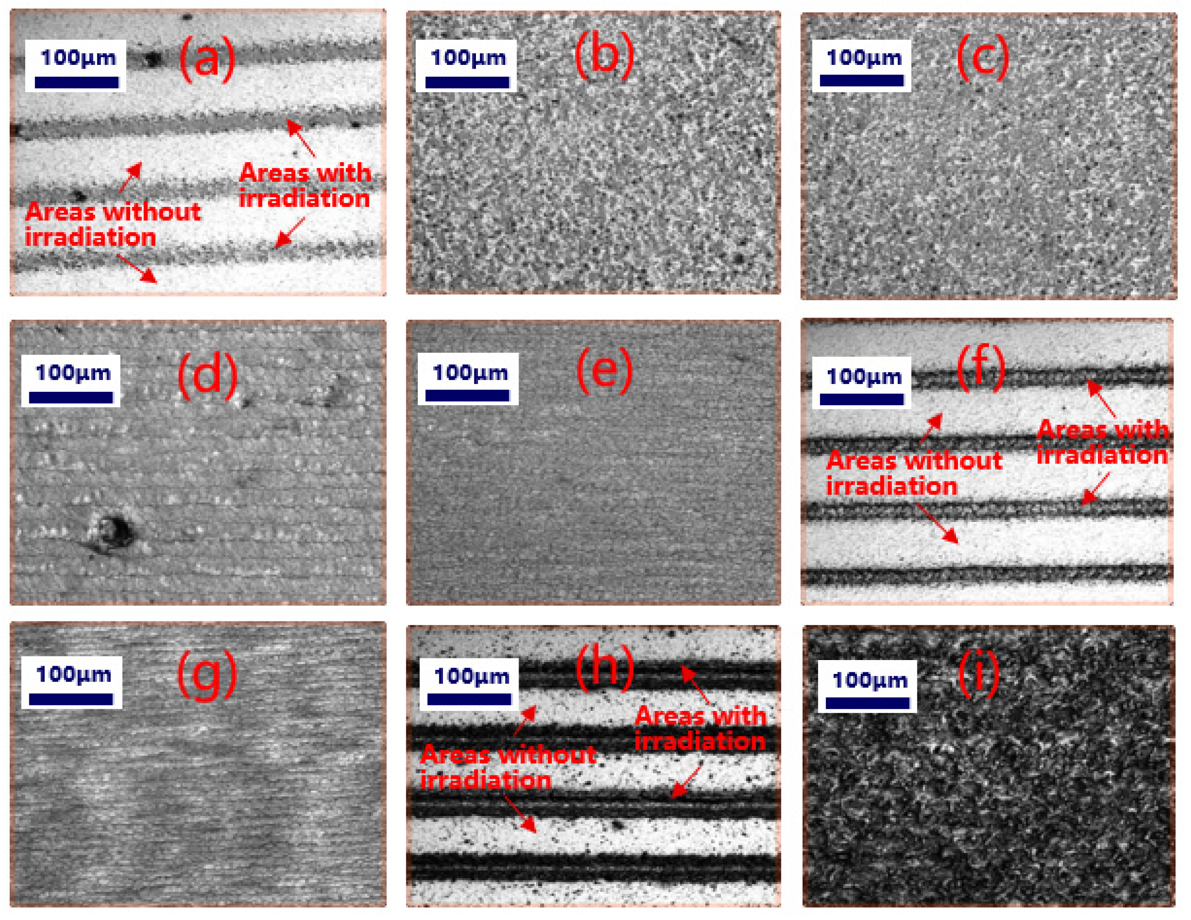
| Regions * | Power (W) | Scanning Speed (mm/s) | Line Spacing (μm) |
|---|---|---|---|
| (a) | 5 | 250 | 100 |
| (b) | 5 | 500 | 10 |
| (c) | 5 | 1000 | 1 |
| (d) | 10 | 250 | 10 |
| (e) | 10 | 500 | 1 |
| (f) | 10 | 1000 | 100 |
| (g) | 15 | 250 | 1 |
| (h) | 15 | 500 | 100 |
| (i) | 15 | 1000 | 10 |
| Cutting Tool | Single-Crystal Diamond Tool |
|---|---|
| Tool nose radius | 1 mm |
| Rake angle | 0° |
| Relief angle | 10° |
| Feed rate | 2 μm/rev |
| Speed of the spindle | 1000 rev/min |
| Depth of cut | 2 μm |
Publisher’s Note: MDPI stays neutral with regard to jurisdictional claims in published maps and institutional affiliations. |
© 2022 by the authors. Licensee MDPI, Basel, Switzerland. This article is an open access article distributed under the terms and conditions of the Creative Commons Attribution (CC BY) license (https://creativecommons.org/licenses/by/4.0/).
Share and Cite
Liu, C.; Xu, K.; Zhang, Y.; Hu, H.; Tao, X.; Zhang, Z.; Deng, W.; Zhang, X. Design and Fabrication of Extremely Lightweight Truss-Structured Metal Mirrors. Materials 2022, 15, 4562. https://doi.org/10.3390/ma15134562
Liu C, Xu K, Zhang Y, Hu H, Tao X, Zhang Z, Deng W, Zhang X. Design and Fabrication of Extremely Lightweight Truss-Structured Metal Mirrors. Materials. 2022; 15(13):4562. https://doi.org/10.3390/ma15134562
Chicago/Turabian StyleLiu, Chen, Kai Xu, Yongqi Zhang, Haifei Hu, Xiaoping Tao, Zhiyu Zhang, Weijie Deng, and Xuejun Zhang. 2022. "Design and Fabrication of Extremely Lightweight Truss-Structured Metal Mirrors" Materials 15, no. 13: 4562. https://doi.org/10.3390/ma15134562