
A Novel NDT Scanning System Based on Line Array Fast Neutron Detector and D-T Neutron Source

Abstract
:1. Introduction
2. Facility
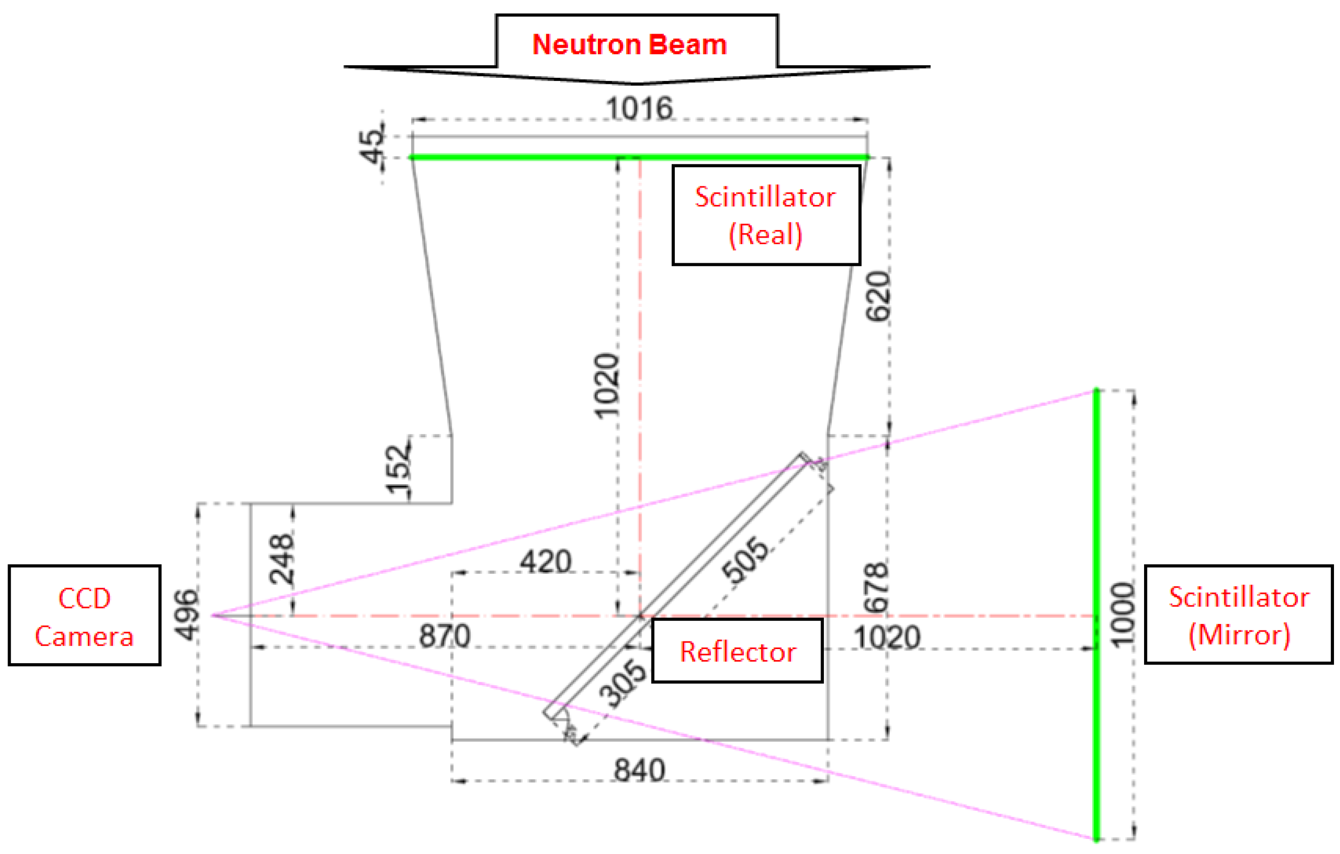
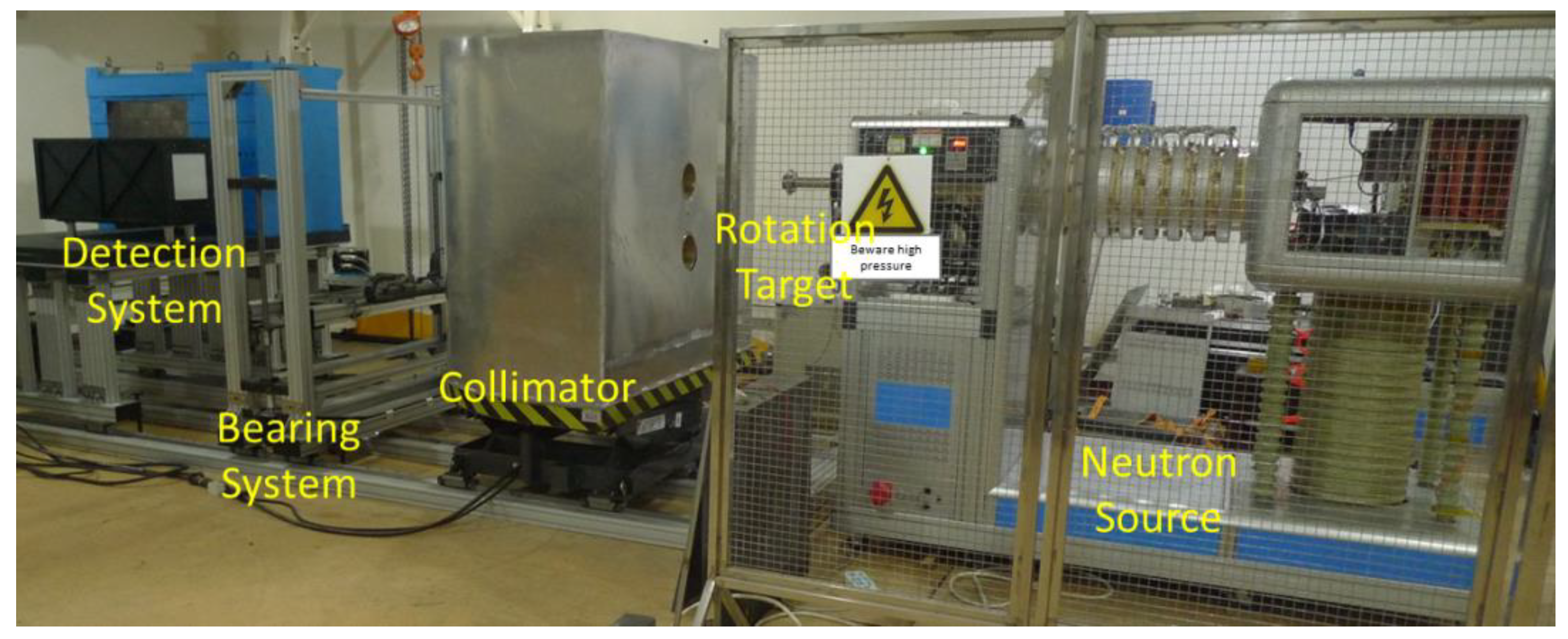
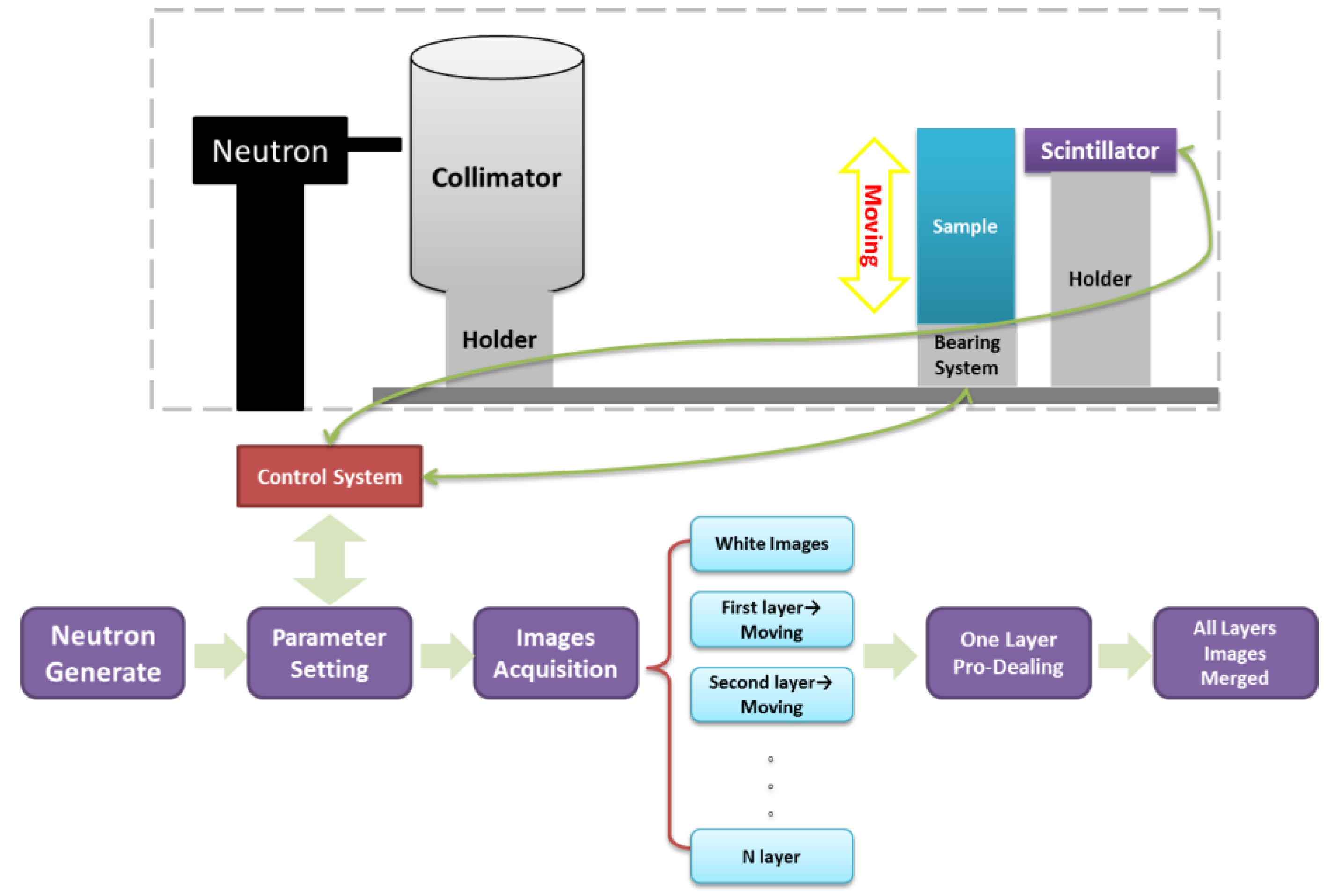
2.1. System Overview
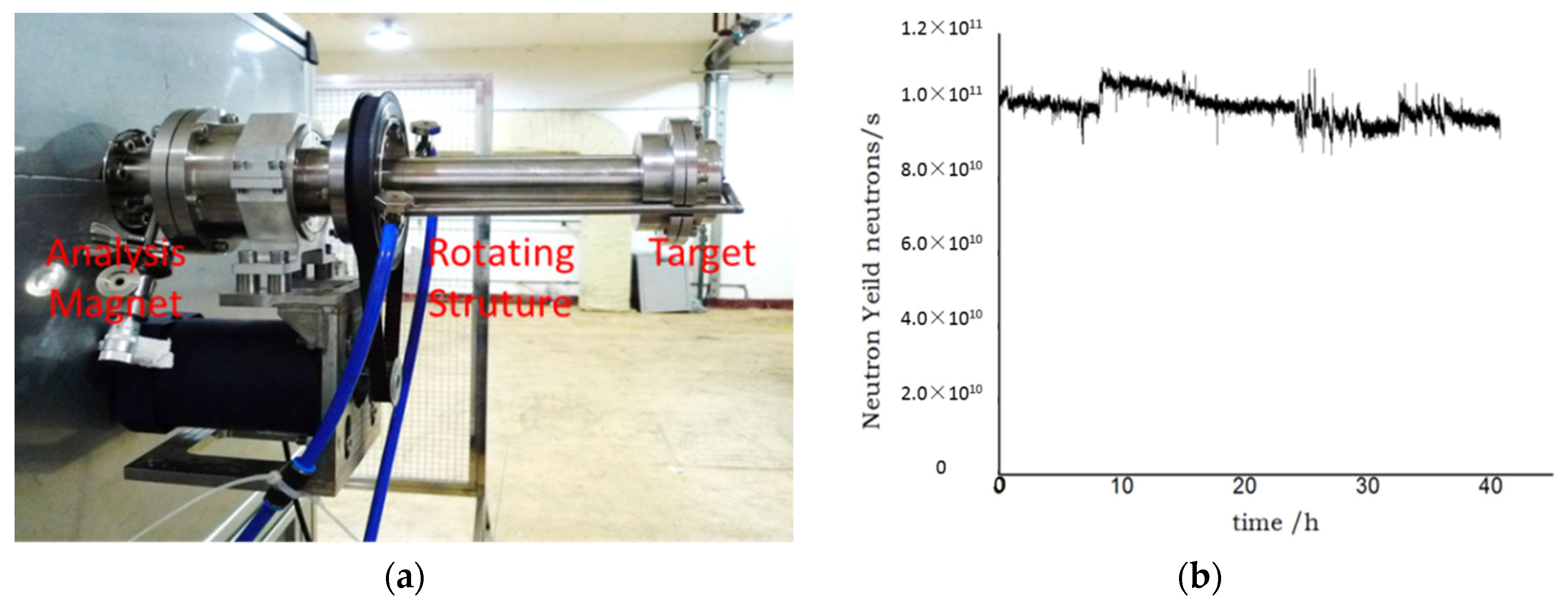
2.2. Neutron Source
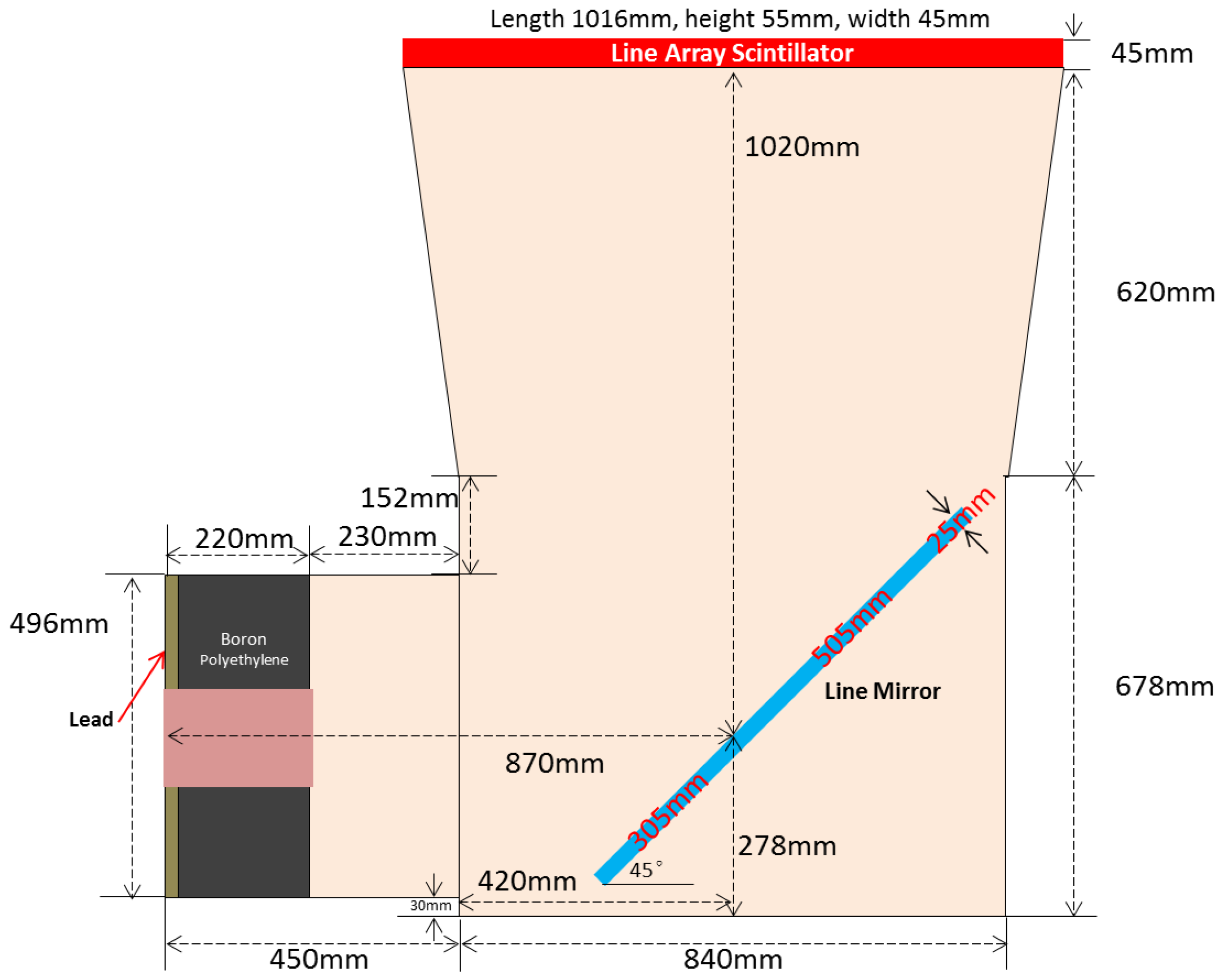
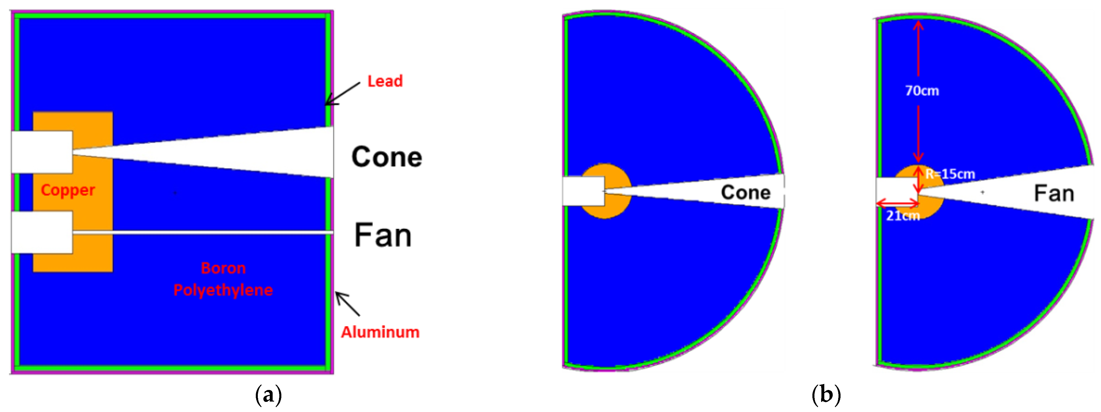
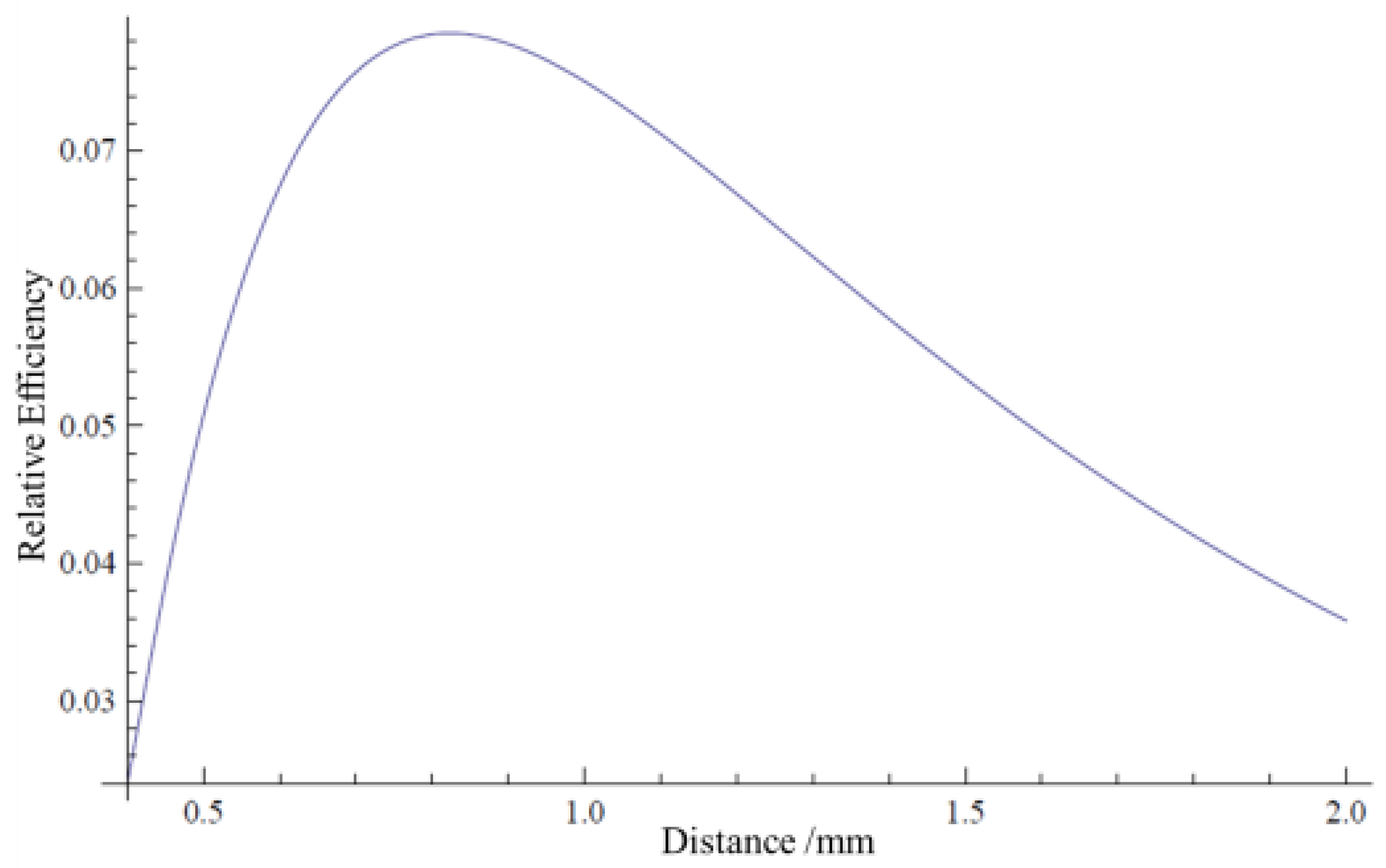
2.3. Collimator
2.4. Line Array Scintillator
2.5. Imaging System
3. Imaging Results
3.1. Scanning Imaging
3.2. Fast Neutron Tomography
4. Conclusions
Author Contributions
Funding
Institutional Review Board Statement
Informed Consent Statement
Data Availability Statement
Conflicts of Interest
References
- Lehmann, E.H.; Vontobel, P.; Hermann, A. Non-destructive analysis of nuclear fuel by means of thermal and cold neutrons. Nucl. Instrum. Methods Phys. Res. Sect. A 2003, 515, 745–759. [Google Scholar] [CrossRef]
- Lehmann, E.H.; Kaestner, A.; Josic, L.; Hartmann, S.; Mannes, D. Imaging with cold neutrons. Nucl. Instrum. Methods Phys. Res. Sect. A 2011, 651, 161–165. [Google Scholar] [CrossRef]
- Strickland, J.; Tassenberg, K.; Sheppard, G.; Nenchev, B.; Perry, S.; Li, J.; Dong, H.B.; Burca, G.; Kelleher, J.; Irwin, S. 2D single crystal Bragg-dip mapping by time-of-flight energy-resolved neutron imaging on IMAT@ISIS. Sci. Rep. 2020, 10, 20751. [Google Scholar] [CrossRef] [PubMed]
- Ryzeewski, K.; Herringer, S.; Bilheux, H.; Walker, L.; Sheldon, B.; Voisin, S.; Bilheux, J.C.; Finocchiaro, V. Neutron Imaging of Archaeological Bronzes at the Oak Ridge National Laboratory. Phys. Procedia 2013, 43, 343–351. [Google Scholar] [CrossRef] [Green Version]
- Bingham, P.; Santos-Villalobos, H.; Lavrik, N.; Gregor, J.; Bilheux, H. Magnified Neutron Radiography with Coded Sources. Phys. Procedia 2015, 69, 218–226. [Google Scholar] [CrossRef] [Green Version]
- Bücherl, T.; von Gostomski, C.L.; Breitkreutz, H.; Jungwirth, M.; Wagner, F.M. NECTAR—A fission neutron radiography and tomography facility. Nucl. Instrum. Methods Phys. Res. Sect. A 2011, 651, 86–89. [Google Scholar] [CrossRef]
- Nelson, R.O.; Vogel, S.C.; Hunter, J.F.; Watkins, E.B.; Losko, A.S.; Tremsin, A.S.; Borges, N.P.; Cutler, T.E.; Dickman, L.T.; Espy, M.A.; et al. Neutron Imaging at LANSCE—From Cold to Ultrafast. J. Imaging 2018, 4, 45. [Google Scholar] [CrossRef] [Green Version]
- Lee, S.; Rinckel, T.; Doskow, J.; Sokol, P.E. Three-dimensional (3D) Fast Neutron Tomography at the Low Energy Neutron Source (LENS). Phys. Procedia 2014, 60, 118–124. [Google Scholar] [CrossRef] [Green Version]
- Dangendorf, V.; Laczko, G.; Reginatto, M.; Vartsky, D.; Goldberg, M.; Mor, I.; Breskin, A.; Chechik, R. Detectors for time-of-flight fast-neutron radiography 1. Neutron-counting gas detector. Nucl. Instrum. Methods Phys. Res. Sect. A 2005, 542, 197–205. [Google Scholar] [CrossRef] [Green Version]
- Daniels, G.C.; Franklyn, C.B.; Dangendorf, V.; Buffler, A.; Bromberger, B. Fast neutron radiography at an RFQ accelerator system. Phys. Procedia 2015, 69, 109–114. [Google Scholar] [CrossRef] [Green Version]
- Pei, Y.Y.; Zou, Y.B.; Guo, Z.Y.; Tang, G.Y.; Xu, J.G.; Guo, J.M.; Zhang, G.H.; Guo, L.A. Research on neutron radiography of accelerator neutron source using D-Be reaction. Nucl. Tech. 2007, 4, 265–268. [Google Scholar]
- Tang, B.; Zhou, C.G.; Huo, H.Y.; Wu, Y.; Liu, B.; Lou, B.C.; Sun, Y. The pilot experimental study of 14 MeV fast neutron digital radiography. Sci. China 2009, 39, 1090–1096. [Google Scholar] [CrossRef]
- Wang, S.; Yin, W.; Liu, B.; Li, H.; Sun, Y.; Cao, C.; Wu, Y.; Huo, H.Y.; Zhu, S.L.; Lou, B.C.; et al. A moveable neutron imaging facility using D-T neutron source based on a compact accelerator. Appl. Radiat. Isot. 2021, 169, 109564. [Google Scholar] [CrossRef] [PubMed]
- Wang, S.; Yin, W.; Li, H.; Sun, Y.; Cao, C.; Wu, Y.; Huo, H.Y.; Zhu, S.L.; Lou, B.C.; Wu, C.L.; et al. Experimental study of thermal neutron tomography based on D-T neutron source with mobile compact accelerator. At. Energy Sci. Technol. 2019, 53, 739–746. [Google Scholar]
- Yin, W.; Wang, S.; Li, H.; Lou, B.C.; Wu, Y.; Huo, H.Y.; Cao, C.; Sun, Y.; Liu, B.; Zhu, S.L.; et al. Experimental study of fast neutron tomography based on an compact accelerator neutron source. Nucl. Tech. 2019, 24, 040201. [Google Scholar]
- Connolly, C. X-ray systems for security and industrial inspection. Sens. Rev. 2008, 28, 194–198. [Google Scholar] [CrossRef]
- Xiang, D.; Guo, L.Y.; Ling, Q.; Zhao, L.H.; Qu, G.P. X ray Line Sensor Scanning Radiograph. J. Nanhua Univ. (Sci. Technol.) 2006, 20, 23–25. [Google Scholar]
- Tang, B.; Wu, Y.; Li, H.; Sun, Y.; Huo, H.Y.; Liu, B.; Tang, K.; Yin, W.; Cao, C. The physics analysis and experiment study of zinc sulphide scintillator for fast neutron radiography. Nucl. Instrum. Methods Phys. Res. A 2013, 729, 327–333. [Google Scholar] [CrossRef]
- Li, H.; Wu, Y.; Cao, C.; Huo, H.Y.; Tang, B. Design optimization, manufacture and response measurements for fast-neutron radiography converters made of scintillator and wavelength-shifting fibers. Nucl. Instrum. Methods Phys. Res. A 2014, 762, 64–69. [Google Scholar] [CrossRef]
- Wu, Y.; Huo, H.Y.; Li, H.; Wang, S.; Cao, C.; Sun, Y.; Yin, W.; Liu, B.; Tang, B. Study on Optical Fiber Conversion Screen for 14 MeV Fast Neutron Radiography. At. Energy Sci. Technol. 2019, 53, 2460. [Google Scholar]
- Vala, S.; Abhangi, M.; Kumar, R.; Sarkar, B.; Bandopadhyay, M. Rotating tritium target for intense 14-MeV neutron source. Fusion Eng. Des. 2017, 123, 77–81. [Google Scholar] [CrossRef]
- Ren, H.T.; Peng, S.X.; Lu, P.N.; Yan, S.; Zhou, Q.F.; Zhao, J.; Yuan, Z.X.; Guo, Z.Y.; Chen, J.E. Intense beams from gases generated by a permanent magnet ECR ion source at PKU. Rev. Sci. Instrum. 2012, 83, 02B905. [Google Scholar]
- Agostinelli, S.; Allison, J.; Amako, K.; Apostolakis, J.; Araujo, H.; Arcelmx, P.; Asaig, M.; Axen, D.; Banerjee, S.; Barrand, G.; et al. Geant4—A simulation toolkit. Nucl. Instrum. Methods Phys. Res. A 2003, 506, 250–303. [Google Scholar] [CrossRef] [Green Version]
- Chadwick, M.B.; Oblozinský, P.; Herman, M.; Greene, N.M.; McKnight, R.D.; Smith, D.L.; Young, P.G.; MacFarlane, R.E.; Hale, G.M.; Frankle, S.C.; et al. ENDF/B-VII.0: Next generation evaluated nuclear data library for nuclear science and Technology. Nucl. Data Sheets 2006, 107, 2931–3060. [Google Scholar] [CrossRef] [Green Version]
- Gordon, R.; Bender, R.; Herman, G.T. Algebraic Reconstruction Techniques (ART) for three-dimensional electron microscopy and X-ray photography. J. Theor. Biol. 1970, 29, 471–476. [Google Scholar] [CrossRef]


| Facility Name | Accelerator Type | Neutron Flux (n/cm2/s) | Field of View (mm) | Spatial Resolution (mm) | Tomography |
|---|---|---|---|---|---|
| This Facility | Cascade | ~2 × 10⁵ | 1000 | 0.5 | yes |
| LENS [8] | Linac | ~1 × 10⁶ | 200 | 0.2 | yes |
| PTB Accelerator Facility [9] | Linac | 2–4 × 10⁵ | 330 | ~0.5 | no |
| Necsa RFQ Facility [10] | Linac | ~1.5 × 10⁴ | ~200 | ~0.4 | no |
Publisher’s Note: MDPI stays neutral with regard to jurisdictional claims in published maps and institutional affiliations. |
© 2022 by the authors. Licensee MDPI, Basel, Switzerland. This article is an open access article distributed under the terms and conditions of the Creative Commons Attribution (CC BY) license (https://creativecommons.org/licenses/by/4.0/).
Share and Cite
Wang, S.; Cao, C.; Yin, W.; Wu, Y.; Huo, H.; Sun, Y.; Liu, B.; Yang, X.; Li, R.; Zhu, S.; et al. A Novel NDT Scanning System Based on Line Array Fast Neutron Detector and D-T Neutron Source. Materials 2022, 15, 4946. https://doi.org/10.3390/ma15144946
Wang S, Cao C, Yin W, Wu Y, Huo H, Sun Y, Liu B, Yang X, Li R, Zhu S, et al. A Novel NDT Scanning System Based on Line Array Fast Neutron Detector and D-T Neutron Source. Materials. 2022; 15(14):4946. https://doi.org/10.3390/ma15144946
Chicago/Turabian StyleWang, Sheng, Chao Cao, Wei Yin, Yang Wu, Heyong Huo, Yong Sun, Bin Liu, Xin Yang, Rundong Li, Shilei Zhu, and et al. 2022. "A Novel NDT Scanning System Based on Line Array Fast Neutron Detector and D-T Neutron Source" Materials 15, no. 14: 4946. https://doi.org/10.3390/ma15144946
APA StyleWang, S., Cao, C., Yin, W., Wu, Y., Huo, H., Sun, Y., Liu, B., Yang, X., Li, R., Zhu, S., Wu, C., Li, H., & Tang, B. (2022). A Novel NDT Scanning System Based on Line Array Fast Neutron Detector and D-T Neutron Source. Materials, 15(14), 4946. https://doi.org/10.3390/ma15144946