
Study on Influencing Factors of Ground Pressure Behavior in Roadway-Concentrated Areas under Super-Thick Nappe

Abstract
:1. Introduction
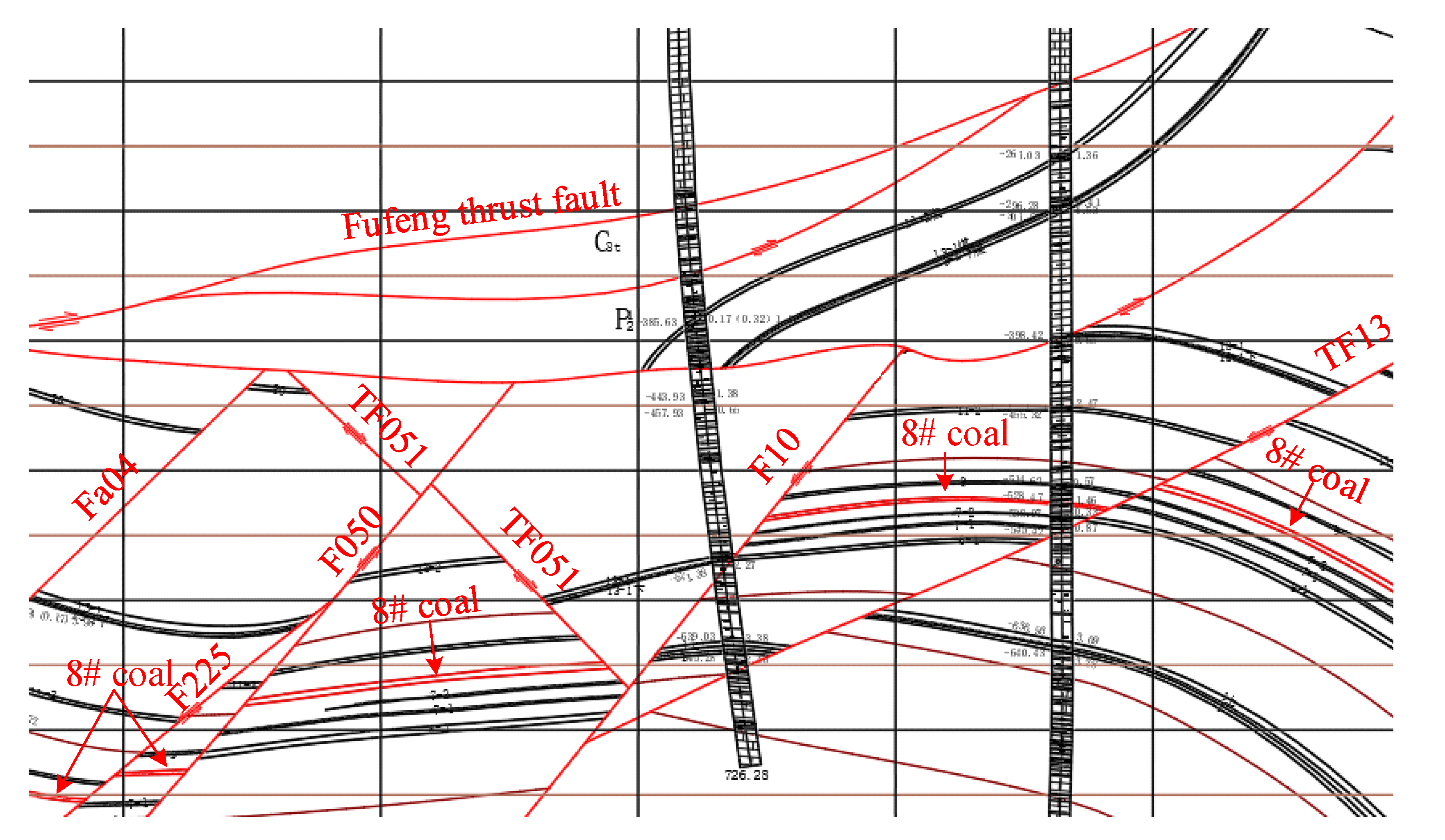
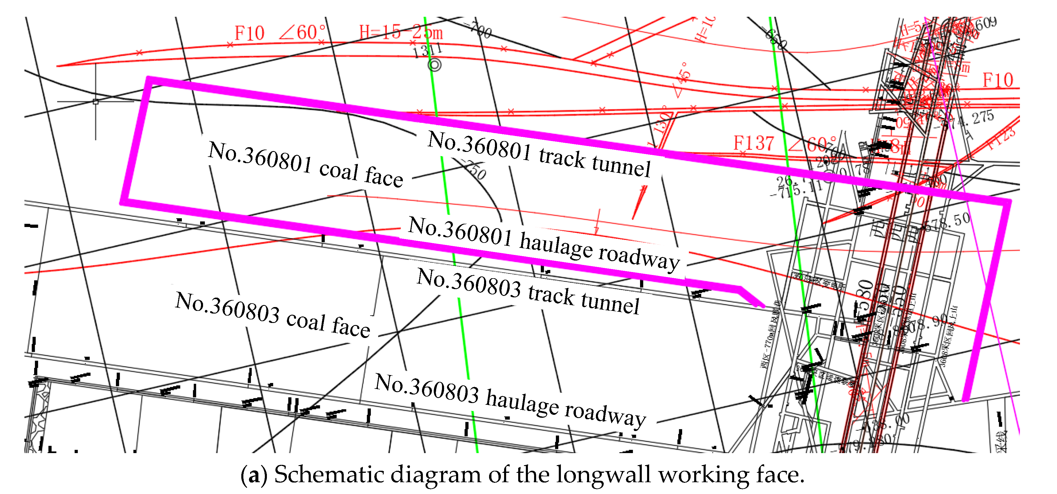
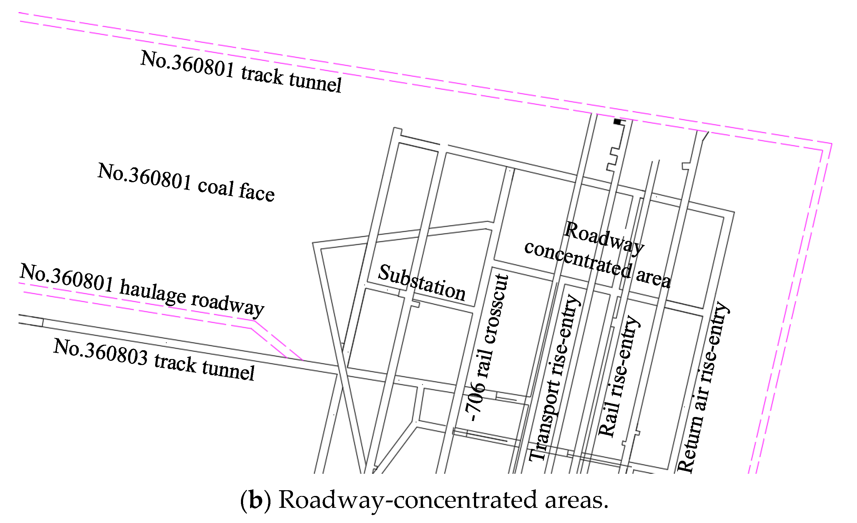
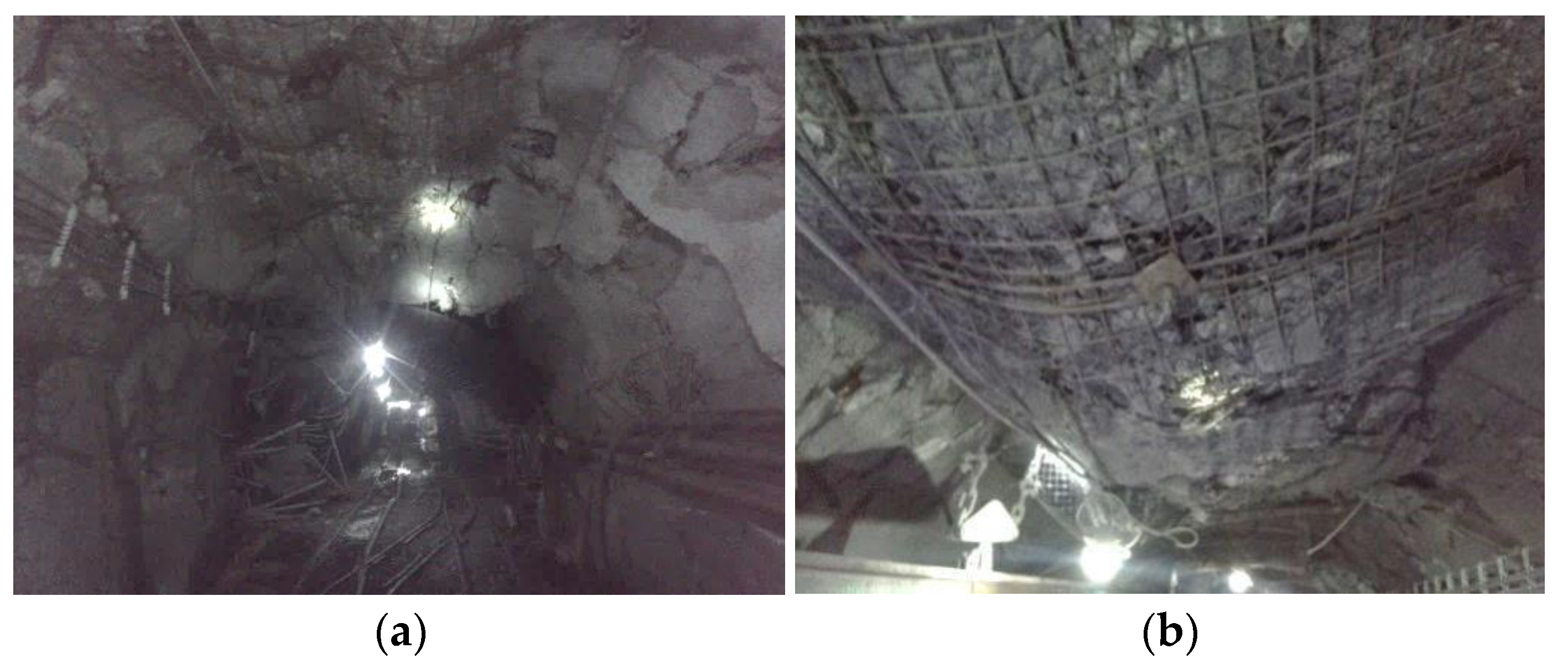
2. Project Profile
3. Factors and Methods
3.1. Analysis of the Main Factors
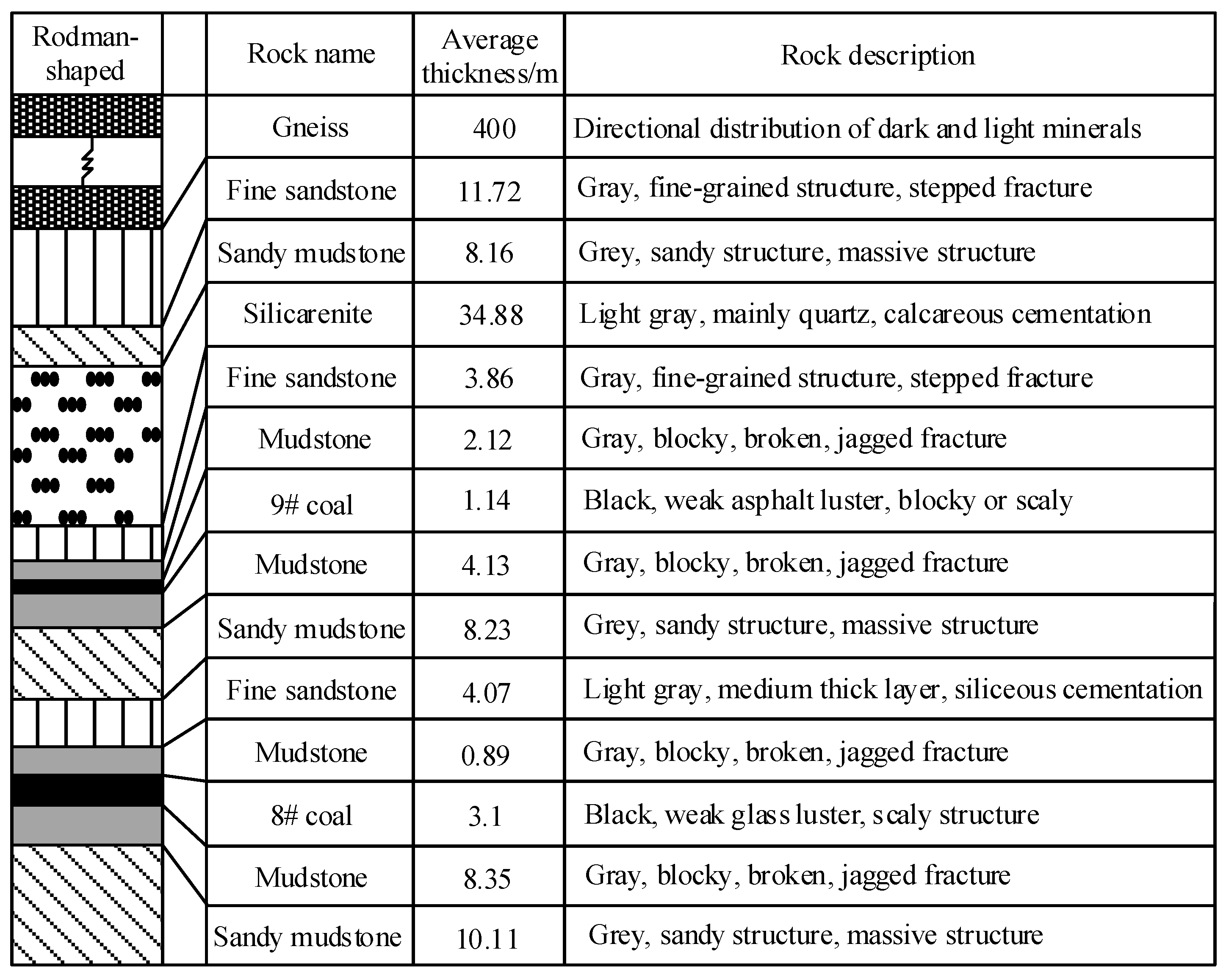
3.1.1. Geologic Factor
- (1)
- Roof lithology
- (2)
- Thickness of nappe
3.1.2. Mining Technological Factors
- (1)
- Mining height
- (2)
- Rise-entry barrier coal pillar size
3.1.3. Time Factor
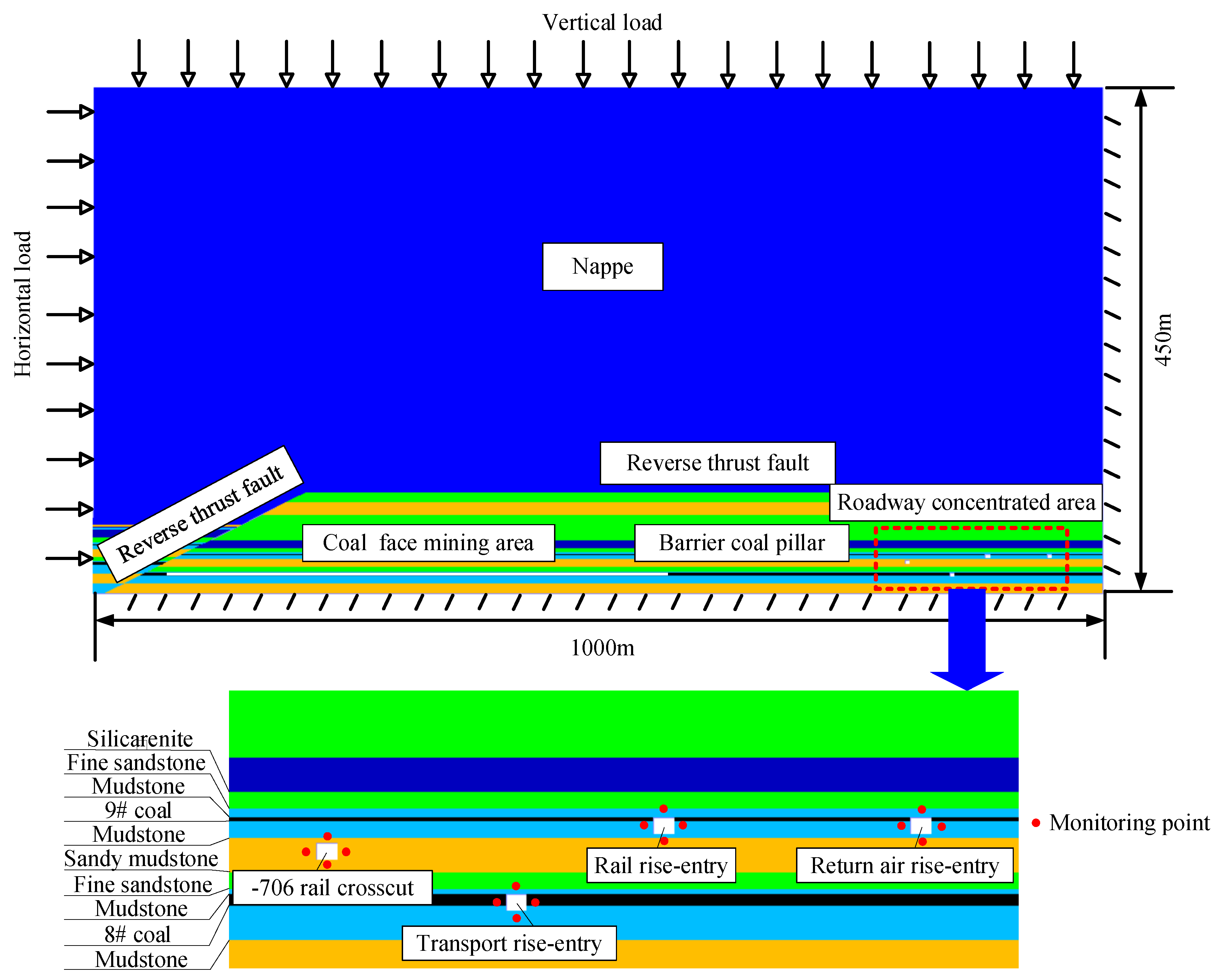
3.2. Construction of the Numerical Model
3.3. Simulation Scheme Design under Different Influence Factors
3.3.1. Geologic Factor
- (1)
- Roof lithology
- (2)
- Thickness of nappe
3.3.2. Mining Technologic Factors
- (1)
- Mining height
- (2)
- Rise-entry barrier coal pillar size
3.3.3. Time Factor
4. Results
4.1. Appearance Law of Ground Pressure Behavior in Roadway-Concentrated Areas under Actual Engineering Conditions
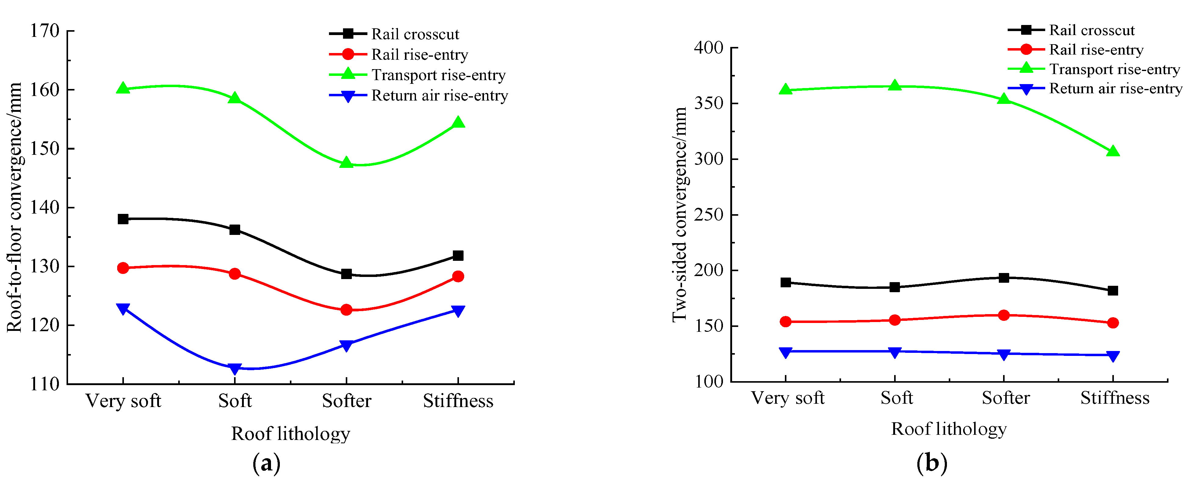
4.2. Influence Law of Roof Lithology
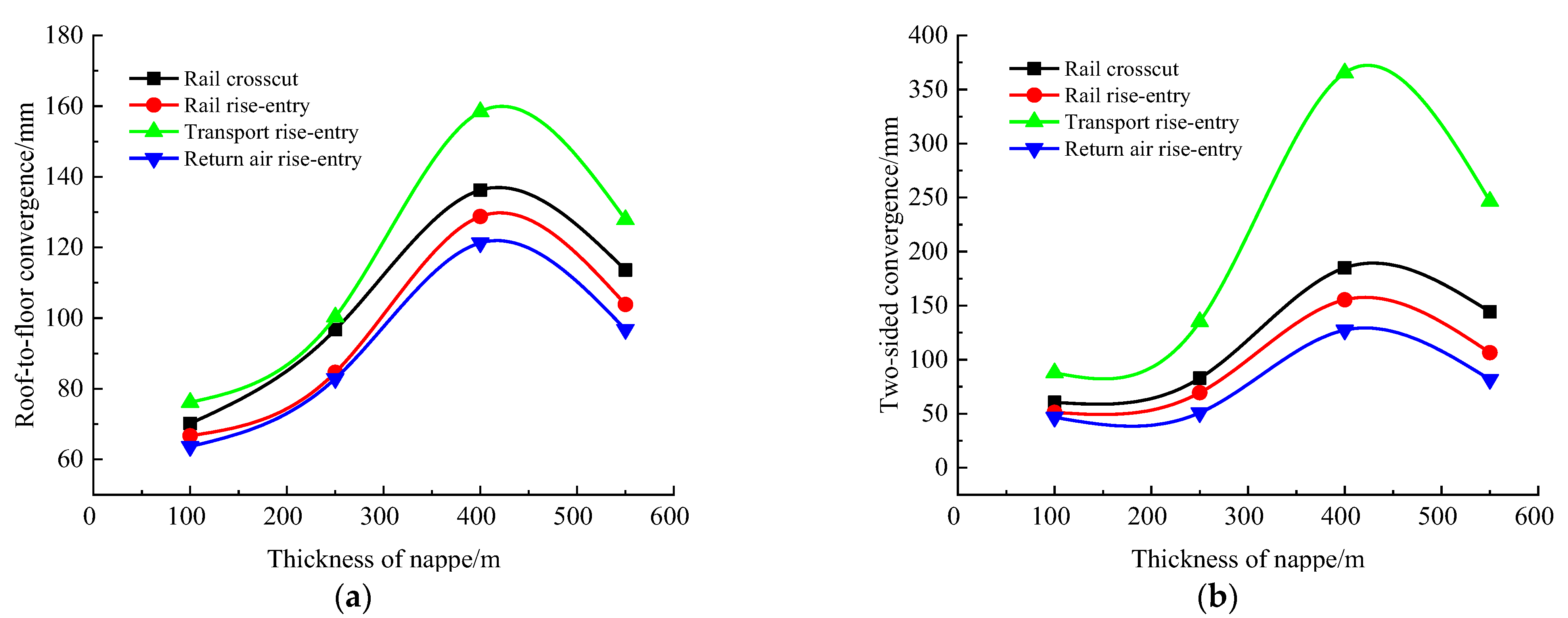
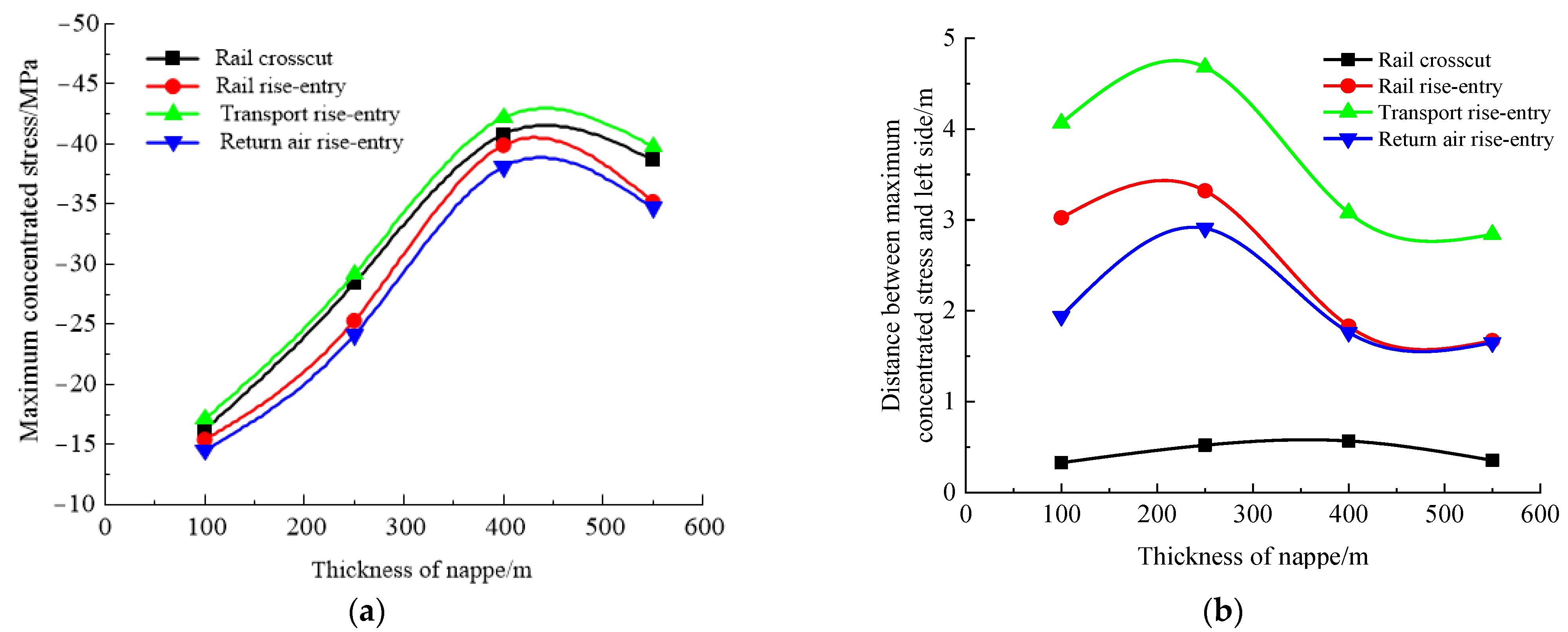
4.3. Influence Law of Nappe Thickness
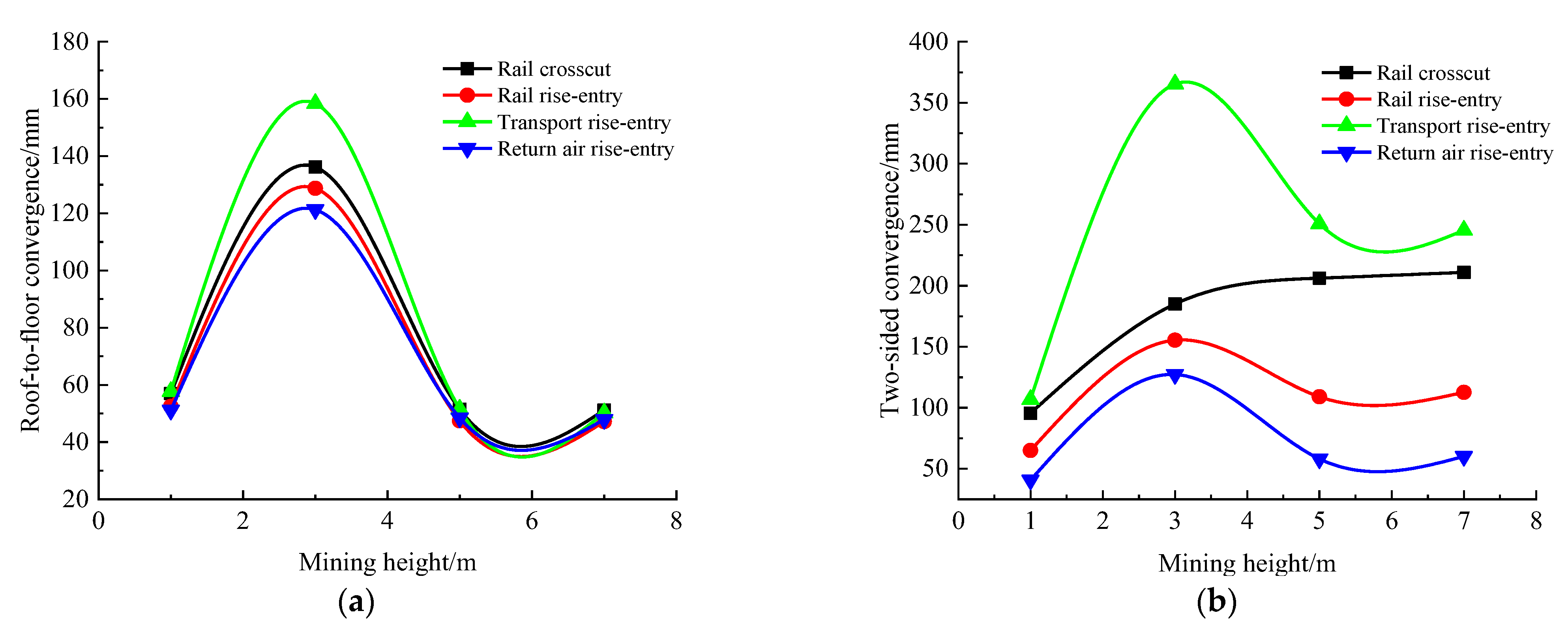
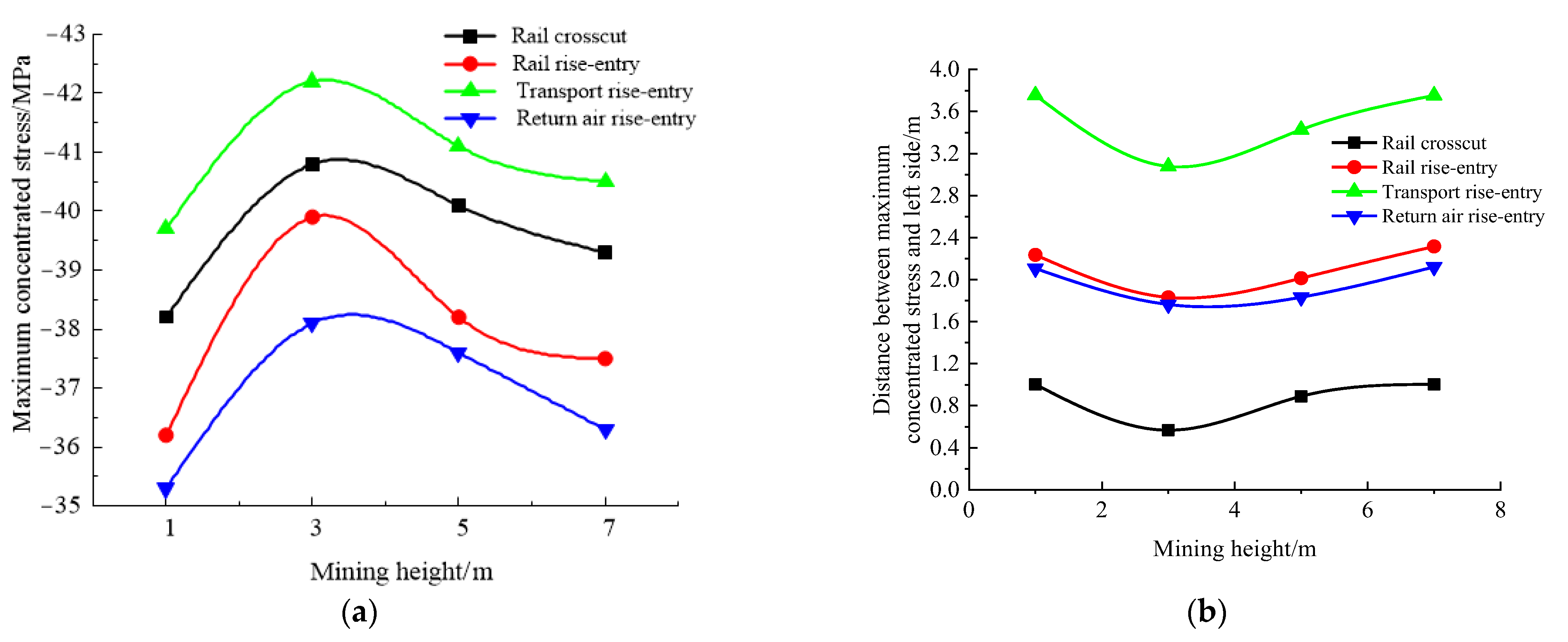
4.4. Influence Law of Mining Height
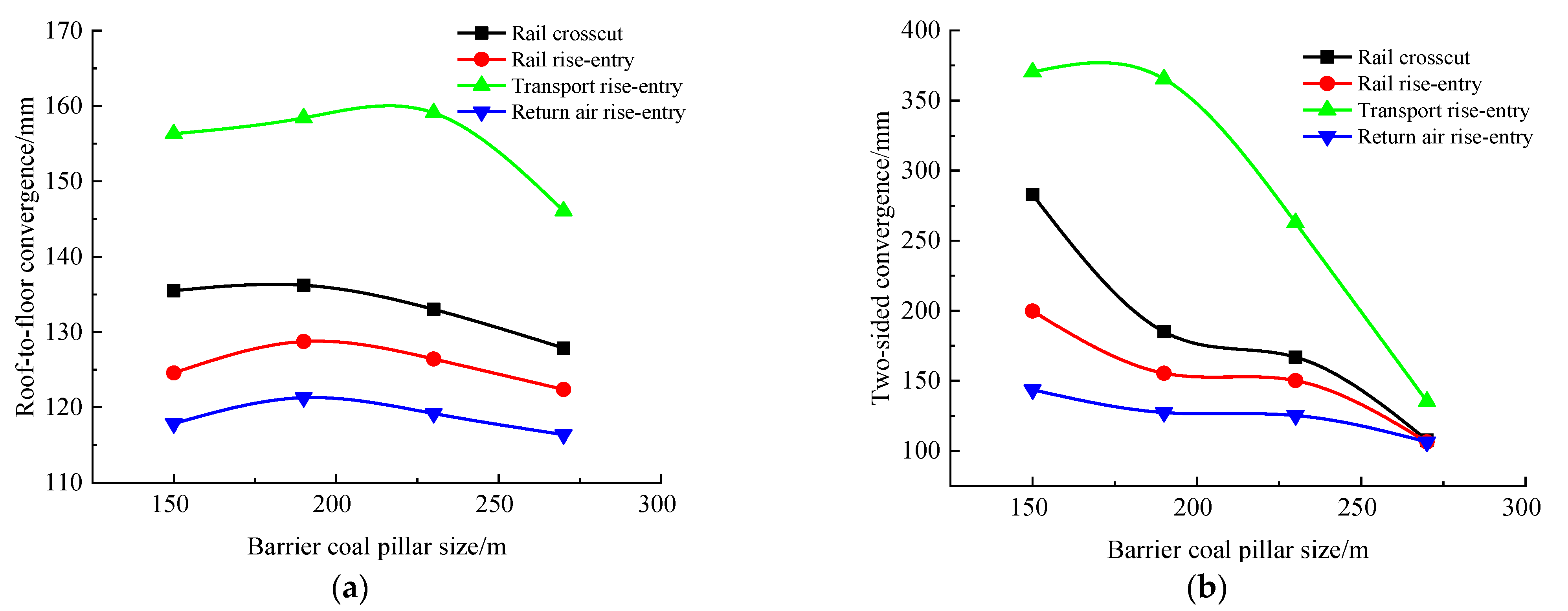
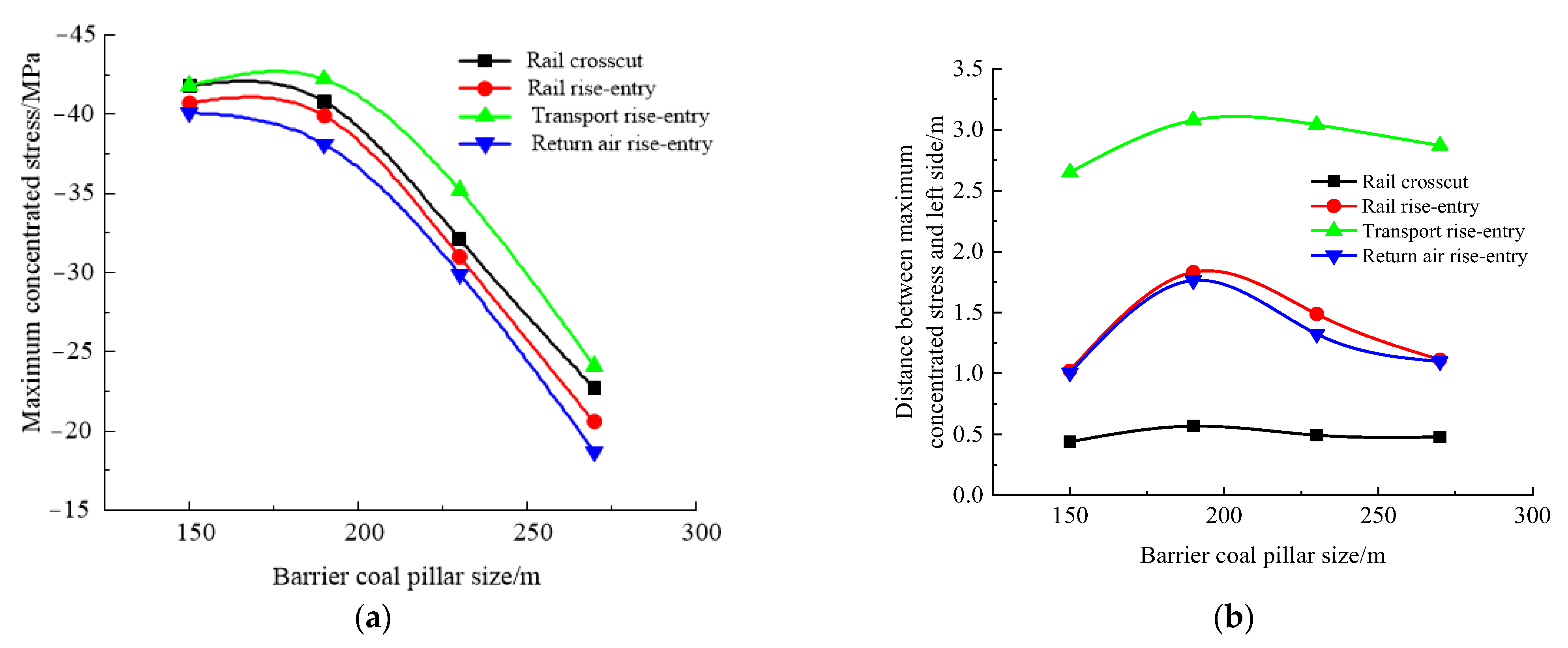
4.5. Influence Law of Rise-Entry Barrier Coal Pillar Size
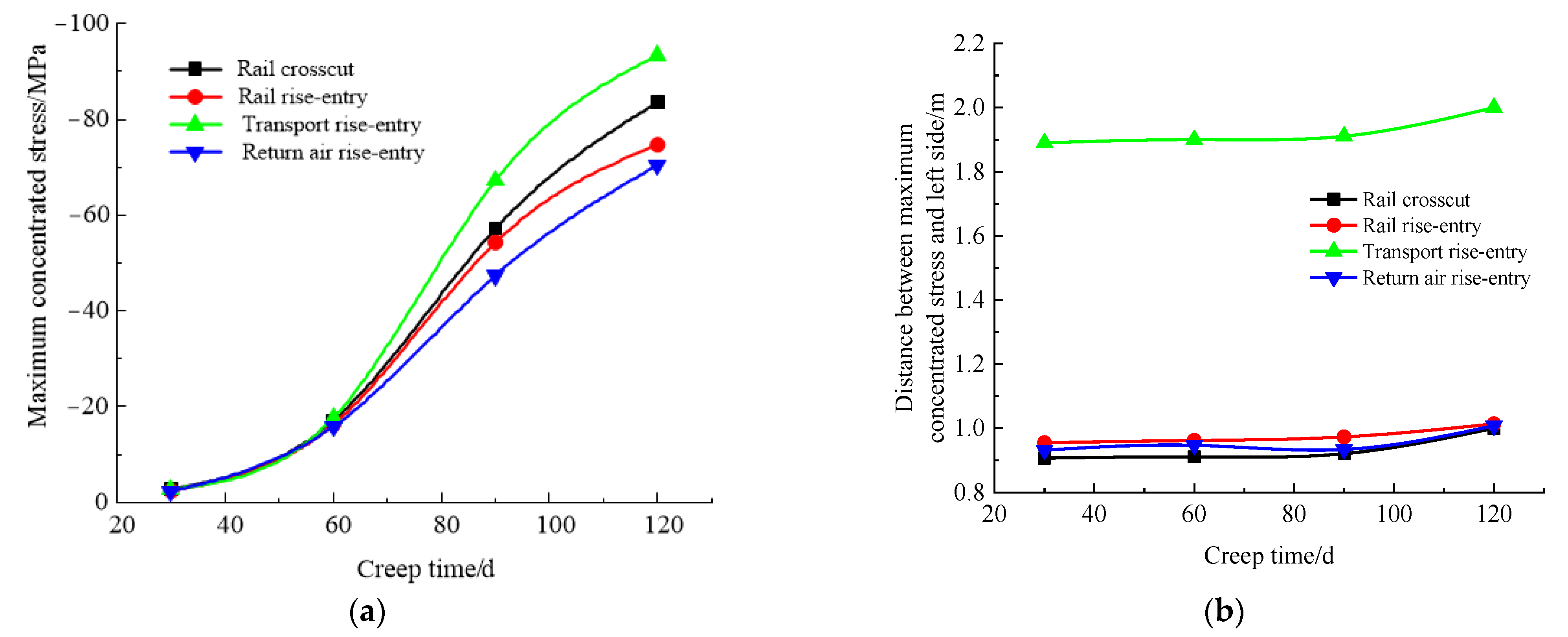
4.6. Influence Law of Creep Time
4.7. Comparative Analysis of Factors
5. Conclusions
- (1)
- According to the actual geological mining conditions of the No. 36 district in the Xinji No. 1 Mine, the influencing factors of ground pressure behavior in roadway-concentrated areas under super-thick nappe were analyzed from three aspects: geological factors, mining technology factors, and time factors. The main influencing factors were determined as roof lithology, the thickness of the nappe, the mining height, the size of the rise-entry barrier coal pillar, and the creep time.
- (2)
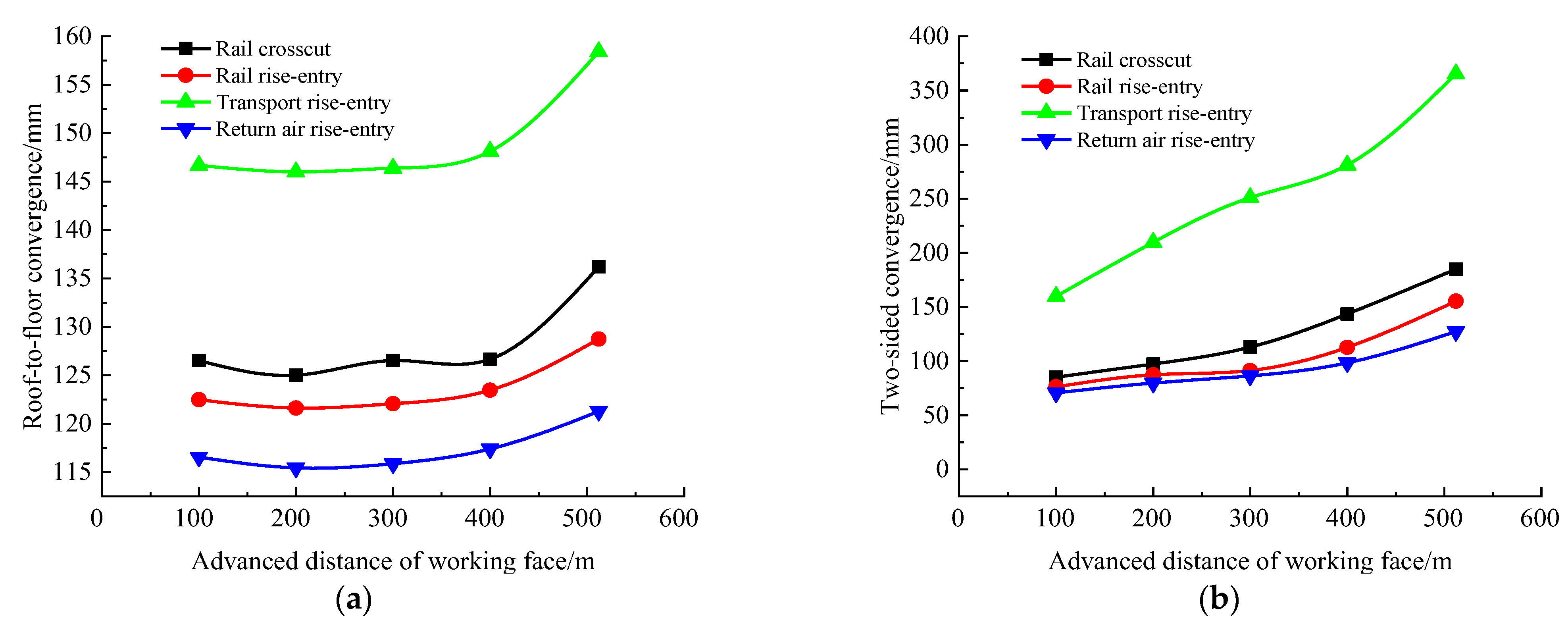
- With the advancement of the No. 360801 coal face, the roof-to-floor convergence, the two-sided convergence, and the maximum concentrated stress of each roadway in the roadway-concentrated areas gradually increased, the distance between the position of the maximum concentrated stress and the side gradually decreased, and the deformation of the two-sided convergence was significantly greater than that of the roof-to-floor convergence. Among them, the two-sided convergence and the maximum concentrated stress can reach 365.4 mm and 42.2 MPa.
- (3)
- By comparing the influence of various factors on the ground pressure behavior in roadway-concentrated areas, it can be concluded that: the greater the thickness of nappe and the greater the mining height, the longer the creep time, the stronger the mine pressure behavior, the greater the size of the rise-entry barrier coal pillar, and the stronger the roof lithology, and the ground pressure behavior tends to be gentle.
- (4)
- By comparing the degree of mine pressure behavior in each roadway under the influence of different factors, it can be found that: The intensity of mine pressure behavior in each roadway was mainly affected by the strata. The closer the roadway was to the coal seam roof, the stronger the mine pressure behavior, while the farther away from the coal seam roof, the gentler the mine pressure behavior. Transport rise-entry was the closest to the coal seam roof, followed by the rail crosscut, so the impact on these two roadways was greater than on the rail rise-entry and the return air rise-entry.
Author Contributions
Funding
Institutional Review Board Statement
Informed Consent Statement
Data Availability Statement
Acknowledgments
Conflicts of Interest
Nomenclature
| Terminology | Representative meaning |
| Thrust fault | A large reverse fault with a dip angle of about 30° or less. |
| Nappe | A huge rock mass structure formed by thrust faults that cause the hanging wall to move thousands or even tens of thousands of meters along the fault plane. |
| Ground pressure behavior | Mine pressure phenomenon shown by surrounding rock movement and support force under the mine pressure. |
| Barrier coal pillar | It refers to the part of the coal body that is specially left underground and is not mined, and the purpose is to protect the above-mentioned protected objects inside the rock stratum and on the surface from mining. |
| Creep | The phenomenon that the deformation of rock increases with time under the continuous action of an external force whose size and direction do not change. |
| Numerical simulation | By means of electronic computers, combined with the concept of finite element or finite volume, through numerical calculation and image display, with the purpose of studying engineering and physical problems and even various problems in nature. |
| Gneiss | Rocks formed by deep metamorphism of magmatic or sedimentary rocks. |
| Immediate roof | Refers to the rock strata directly above the ore layer and can fall down in time during caving. |
| Main roof | The roof located on the direct roof or coal seam, also known as the old roof. Usually large thickness and rock strength, difficult to collapse rock. |
| Rail crosscut | Transport is the main task in the inner track of the connecting roadway through the coal seam. |
| Rail rise-entry | Inclined roadway upward from the transport layer. |
| Transport rise-entry | Roadways for transporting ores when mining deposits above the mining level. |
| Return air rise-entry | A roadway extending upward from a mining level for ventilation. |
| Roof-to-floor convergence | Under the support of hydraulic support, the mining space is affected by mining, the reflection of rock deformation, and movement. |
References
- Kayabasi, A.; Gokceoglu, C. Coal mining under difficult geological conditions: The Can lignite open pit (Canakkale, Turkey). Eng. Geol. 2012, 135, 66–82. [Google Scholar] [CrossRef]
- Zhao, T.; Zhang, Z.; Tan, Y.; Shi, C.; Wei, P.; Li, Q. An innovative approach to thin coal seam mining of complex geological conditions by pressure regulation. Int. J. Rock Mech. Min. Sci. 2014, 71, 249–257. [Google Scholar] [CrossRef]
- Kang, H. Support technologies for deep and complex roadways in underground coal mines: A review. Int. J. Coal Sci. Technol. 2014, 1, 261–277. [Google Scholar] [CrossRef] [Green Version]
- Yao, N.; Yi, W.; Yao, Y.; Song, H.; Li, W.; Peng, T.; Sun, X. Progress of drilling technologies and equipments for complicated geological conditions in underground coal mines in China. Coal Field Geol. Explor. 2020, 48, 1–7. [Google Scholar]
- Elizalde, C.; Griffith, W.A.; Miller, T. Thrust fault nucleation due to heterogeneous bedding plane slip: Evidence from an Ohio coal mine. Eng. Geol. 2016, 206, 1–17. [Google Scholar] [CrossRef]
- Liu, X.; Fan, D.; Tan, Y.; Ning, J.; Song, S.; Wang, H.; Li, X. New detecting method on the connecting fractured zone above the coal face and a case study. Rock Mech. Rock Eng. 2021, 54, 4379–4391. [Google Scholar] [CrossRef]
- Jing, F.; Wei, Q.; Wang, C.; Yao, S.-L.; Zhang, Y.; Han, R.-J.; Wei, X.-Z.; Li, Z.-C. Analysis of rock burst mechanism in extra-thick coal seam controlled by huge thick conglomerate and thrust fault. J. China Coal Soc. 2014, 39, 1191–1196. [Google Scholar]
- Zhao, Y.; Wang, H.; Jiao, Z.; Zhang, X. Experimental study of the activities of reverse fault induced by footwall coal mining. J. China Coal Soc. 2018, 43, 914–922. [Google Scholar]
- Batugin, A.; Wang, Z.; Su, Z.; Sidikovna, S.S. Combined support mechanism of rock bolts and anchor cables for adjacent roadways in the external staggered split-level panel layout. Int. J. Coal Sci. Technol. 2021, 8, 659–673. [Google Scholar] [CrossRef]
- Tan, Y.; Fan, D.; Liu, X.; Song, S.; Li, X.; Wang, H. Numerical investigation on failure evolution of surrounding rock for super-large section chamber group in deep coal mine. Energy Sci. Eng. 2019, 7, 3124–3146. [Google Scholar] [CrossRef] [Green Version]
- Liu, X.; Fan, D.; Tan, Y.; Song, S. Failure evolution and instability mechanism of surrounding rock for close-distance parallel chambers with super-large section in deep coal mines. Int. J. Geomech. 2021, 21, 04021049. [Google Scholar] [CrossRef]
- Wu, Q.; Jiang, L.; Wu, Q. Study on the law of mining stress evolution and fault activation under the influence of normal fault. Acta Geodyn. Geomater. 2017, 14, 357–369. [Google Scholar] [CrossRef] [Green Version]
- Jiao, Z.; Jiang, Y.; Zhao, Y.; Hu, H. Study of dynamic mechanical response characteristics of working face passing through reverse fault. J. China Univ. Min. Technol. 2019, 48, 54–63. [Google Scholar]
- Jiao, Z.; Zhao, Y.; Jiang, Y.; Wang, H.; Lu, Z.G.; Wang, X.Z. Fault damage induced by mining and its sensitivity analysis of influencing factors. J. China Coal Soc. 2017, 42 (Suppl. S1), 36–42. [Google Scholar]
- Sainoki, A.; Schwartzkopff, A.K.; Jiang, L.; Mitri, H.S. Numerical Modeling of Complex Stress State in a Fault Damage Zone and Its Implication on Near-Fault Seismic Activity. J. Geophys. Res. Solid Earth 2021, 126, e2021JB021784. [Google Scholar] [CrossRef]
- Li, Z.; Wang, C.; Shan, R.; Yuan, H.; Zhao, Y.; Wei, Y. Study on the influence of the fault dip angle on the stress evolution and slip risk of normal faults in mining. Bull. Eng. Geol. Environ. 2021, 80, 3537–3551. [Google Scholar] [CrossRef]
- Chen, X.; Li, W.; Yan, X. Analysis on rock burst danger when fully-mechanized caving coal face passed fault with deep mining. Saf. Sci. 2012, 50, 645–648. [Google Scholar] [CrossRef]
- Zhang, X.; Zhou, F.; Zou, J. Numerical Simulation of Gas Extraction in Coal Seam Strengthened by Static Blasting. Sustainability 2022, 14, 12484. [Google Scholar] [CrossRef]
- Cao, A.; Jing, G.; Ding, Y.; Liu, S. Mining-induced static and dynamic loading rate effect on rock damage and acoustic emission characteristic under uniaxial compression. Saf. Sci. 2019, 116, 86–96. [Google Scholar] [CrossRef]
- Cao, A.; Hu, Y.; Li, B. Research and application on anchor cable reinforcement of distressed zone in sidewall along roadway under dynamic disturbance. Coal Sci. Technol. Mag. 2021, 42, 39–46. [Google Scholar]
- Zhang, F.; Cui, L.; An, M.; Elsworth, D.; He, C. Frictional stability of Longmaxi shale gouges and its implication for deep seismic potential in the southeastern Sichuan Basin. Deep. Undergr. Sci Eng. 2022, 1, 3–14. [Google Scholar] [CrossRef]
- Kong, P.; Jiang, L.; Shu, J.; Wang, L. Mining stress distribution and fault-slip behavior: A case study of fault-influenced longwall coal mining. Energies 2019, 12, 2494. [Google Scholar] [CrossRef] [Green Version]
- Wu, Q.; Wu, Q.; Yuan, A.; Wu, Y. Analysis of mining effect and fault stability under the influence of normal faults. Geotech. Geol. Eng. 2021, 39, 49–63. [Google Scholar] [CrossRef]
- Jiao, Z.; Wang, L.; Zhang, M.; Wang, J. Numerical Simulation of Mining-Induced Stress Evolution and Fault Slip Behavior in Deep Mining. Adv. Mater. Sci. Eng. 2021. [Google Scholar] [CrossRef]
- Islan, M.R.; Shinjo, R. Mining-induced fault reactivation associated with the main conveyor belt roadway and safety of the Barapukuria coal mine in Bangladesh: Constraints from BEM simulations. Int. J. Coal Geol. 2009, 79, 115–130. [Google Scholar] [CrossRef]
- Zhang, D.; Duan, Y.; Du, W.; Chai, J. Experimental Study on Physical Similar Model of Fault Activation Law Based on Distributed Optical Fiber Monitoring. Shock. Vib. 2021. [Google Scholar] [CrossRef]
- Wang, A.; Pan, Y.; Li, Z.; Liu, C.S.; Han, R.J.; Lv, X.F.; Lu, H.Q. Similar experimental study of rock burst induced by mining deep coal seam under fault action. Rock Soil Mech. 2014, 35, 2486–2492. [Google Scholar]
- Luo, H.; Li, Z.; Wang, A.; Xiao, Y.-H. Study on the evolution law of stress field when approaching fault in deep mining. J. China Coal Soc. 2014, 39, 322–327. [Google Scholar]
- Wang, H.; Jiang, Y.; Xue, S.; Mao, L.; Lin, Z.; Deng, D.; Zhang, D. Influence of fault slip on mining-induced pressure and optimization of roadway support design in fault-influenced zone. J. Rock Mech. Geotech. Eng. 2016, 8, 660–671. [Google Scholar] [CrossRef] [Green Version]
- Cai, W.; Dou, L.; Wang, G.; Hu, Y. Mechanism of fault reactivation and its induced coal burst caused by coal mining activities. J. Min. Saf. Eng. 2019, 36, 1193–1202. [Google Scholar]
- Babets, D.; Sdvyzhkova, O.; Shashenko, O.; Kravchenko, K.; Cabana, E.C. Implementation of probabilistic approach to rock mass strength estimation while excavating through fault zones. Min. Miner. Depos. 2019, 13, 72–83. [Google Scholar] [CrossRef] [Green Version]
- Han, Z.; Li, D.; Li, X. Dynamic mechanical properties and wave propagation of composite rock-mortar specimens based on SHPB tests. Int. J. Min. Sci. Technol. 2022, 32, 793–806. [Google Scholar] [CrossRef]
- Cao, A.; Chen, F.; Liu, Y.; Dou, L.M.; Wang, C.B.; Yang, X.; Bai, X.Q.; Song, S.K. Response characteristics of rupture mechanism and source parameters of mining tremors in frequent coal burst area. J. China Coal Soc. 2022, 47, 722–733. [Google Scholar]
- Fan, D.; Liu, X.; Tan, Y.; Li, X.; Lkhamsuren, P. Instability energy mechanism of super-large section crossing chambers in deep coal mines. Int. J. Min. Sci. Technol. 2022, 32, 1075–1086. [Google Scholar] [CrossRef]
- Luo, S.; Gong, F. Evaluation of rock burst proneness considering specimen shape by storable elastic strain energy. Deep Underground Sci. Eng. 2022, 1–15. [Google Scholar]
- Ji, H.; Ma, H.; Wang, J.; Zhang, Y.H.; Cao, H. Mining disturbance effect and mining arrangements analysis of near-fault mining in high tectonic stress region. Saf. Sci. 2012, 50, 649–654. [Google Scholar] [CrossRef]
- Potvin, Y.; Jarufe, J.; Wesseloo, J. Interpretation of seismic data and numerical modeling of fault reactivation at El Teniente, Reservas Norte sector. Trans. Inst. Min. Metall. 2015, 119, 175–181. [Google Scholar]
- Begalinov, A.; Almenov, T.; Zhanakova, R.; Bektur, B. Analysis of the stress deformed state of rocks around the haulage roadway of the Beskempir field (Kazakhstan). Min. Miner. Depos. 2020, 14, 28–36. [Google Scholar] [CrossRef]
- Wang, H.; Shi, R.; Song, J.; Tian, Z.; Deng, D.; Jiang, Y. Mechanical model for the calculation of stress distribution on fault surface during the underground coal seam mining. Int. J. Rock Mech. Min. Sci. 2021, 144, 104765. [Google Scholar] [CrossRef]
- Dokht, R.M.H.; Smith, B.; Kao, H.; Visser, R.; Hutchinson, J. Reactivation of an intraplate fault by mine-blasting events: Implications to regional seismic hazard in Western Canada. J. Geophys. Res. Solid Earth 2020, 125. [Google Scholar] [CrossRef]
- Pan, C.; Xia, B.; Zuo, Y.; Yu, B.; Ou, C. Mechanism and control technology of strong ground pressure behavior induced by high-position hard roofs in extra-thick coal seam mining. Int. J. Min. Sci. Technol. 2022, 32, 499–511. [Google Scholar] [CrossRef]
- Tan, Y.L.; Liu, X.S.; Shen, B.; Ning, J.G.; Gu, Q.H. New approaches to testing and evaluating the impact capability of coal seam with hard roof and/or floor in coal mines. Geomech. Eng. 2018, 14, 367–376. [Google Scholar]
- Liu X, S.; Tan Y, L.; Ning J, G.; Lu, Y.W.; Gu, Q.H. Mechanical properties and damage constitutive model of coal in coal-rock combined body. Int. J. Rock Mech. Min. Sci. 2018, 110, 140–150. [Google Scholar] [CrossRef]
- Małkowski, P.; Niedbalski, Z.; Balarabe, T. A statistical analysis of geomechanical data and its effect on rock mass numerical modeling: A case study. Int. J. Coal Sci. Technol. 2021, 8, 312–323. [Google Scholar] [CrossRef]


| Rock Name | Thickness | Density/kg × m−3 | Tensile Strength/MPa | Elastic Modulus/GPa | Cohesion/MPa | The Angle of Internal Friction/° | Poisson’d Ratio | |
|---|---|---|---|---|---|---|---|---|
| 1 | Gneiss | 400 | 2763 | 11.2 | 44.8 | 15 | 40 | 0.25 |
| 2 | Fine sandstone | 12 | 2532 | 5.38 | 37.15 | 3.2 | 42 | 0.27 |
| 3 | Sandy mudstone | 8 | 2562 | 2.6 | 12.08 | 2.45 | 40 | 0.25 |
| 4 | Silicarenite | 35 | 2423 | 4.9 | 21.75 | 21 | 75 | 0.29 |
| 5 | Fine sandstone | 4 | 2532 | 5.38 | 37.15 | 3.2 | 42 | 0.27 |
| 6 | Mudstone | 2 | 2582 | 2.0 | 10.37 | 1.2 | 32 | 0.28 |
| 7 | No. 9 coal seam | 1 | 1401 | 0.3 | 2.79 | 0.8 | 29 | 0.32 |
| 8 | Mudstone | 4 | 2582 | 2.0 | 10.37 | 1.2 | 32 | 0.28 |
| 9 | Sandy mudstone | 8 | 2562 | 2.6 | 12.08 | 2.45 | 40 | 0.25 |
| 10 | Fine sandstone | 4 | 2532 | 5.38 | 37.15 | 3.2 | 42 | 0.27 |
| 11 | Mudstone | 1 | 2582 | 2.0 | 10.37 | 1.2 | 32 | 0.28 |
| 12 | No. 8 coal seam | 3 | 1378 | 0.4 | 1.32 | 0.8 | 29 | 0.31 |
| 13 | Mudstone | 8 | 2582 | 2.0 | 10.37 | 1.2 | 32 | 0.28 |
| 14 | Sandy mudstone | 10 | 2562 | 2.6 | 12.08 | 2.45 | 40 | 0.25 |
| Name | Simulation Scheme | Specific Parameters | |||||
|---|---|---|---|---|---|---|---|
| Density/kg·m−3 | Bulk Modulus/GPa | Shear Modulus/GPa | Internal Friction Angle/° | Cohesion/MPa | Tensile Strength/MPa | ||
| Roof lithology | Very soft | 1378 | 2.8 | 1.51 | 32 | 0.3 | 0.945 |
| Soft | 2582 | 4.23 | 2.3 | 40 | 0.3 | 2.4 | |
| Softer | 2532 | 8.64 | 5.69 | 38 | 2.1 | 4.5 | |
| Stiff | 2532 | 12.64 | 8.69 | 36 | 5.2 | 11.5 | |
Disclaimer/Publisher’s Note: The statements, opinions and data contained in all publications are solely those of the individual author(s) and contributor(s) and not of MDPI and/or the editor(s). MDPI and/or the editor(s) disclaim responsibility for any injury to people or property resulting from any ideas, methods, instructions or products referred to in the content. |
© 2022 by the authors. Licensee MDPI, Basel, Switzerland. This article is an open access article distributed under the terms and conditions of the Creative Commons Attribution (CC BY) license (https://creativecommons.org/licenses/by/4.0/).
Share and Cite
Zhu, R.; Yue, X.; Liu, X.; Shi, Z.; Li, X. Study on Influencing Factors of Ground Pressure Behavior in Roadway-Concentrated Areas under Super-Thick Nappe. Materials 2023, 16, 89. https://doi.org/10.3390/ma16010089
Zhu R, Yue X, Liu X, Shi Z, Li X. Study on Influencing Factors of Ground Pressure Behavior in Roadway-Concentrated Areas under Super-Thick Nappe. Materials. 2023; 16(1):89. https://doi.org/10.3390/ma16010089
Chicago/Turabian StyleZhu, Ruojun, Xizhan Yue, Xuesheng Liu, Zhihan Shi, and Xuebin Li. 2023. "Study on Influencing Factors of Ground Pressure Behavior in Roadway-Concentrated Areas under Super-Thick Nappe" Materials 16, no. 1: 89. https://doi.org/10.3390/ma16010089