Abstract
The incorporation of sustainability into the design of transport vehicles has become increasingly important in recent years. A low carbon footprint makes wood-based structures attractive to replace other lightweight materials such as aluminum or fiber-reinforced plastics. This paper investigates and compares the static and dynamic impact behavior of thin Beech wood veneer laminates in standardized mechanical tests. The results obtained from Quasi-Static Indentation (QSI) and dynamic Low-Velocity Impact (LVI) tests reveal similarities and differences with regard to load vs. displacement behavior, damage mechanisms, permanent deformation, and energy absorption. While yield strength and damage modes are comparable in both test cases, it is found that the bending stiffness is strain-rate sensitive. Plastic deformation in compression is identified as the governing mechanism for energy absorption. These results can guide the design of sustainable wood-based structures for future transport applications where a thorough understanding of impact and crashworthiness is important.
1. Introduction
Wood-based materials have the potential to significantly reduce the world’s greenhouse gas emissions thanks to their carbon-storing capabilities. This motivates exploration of the use of wood in non-conventional applications such as transport vehicles, in particular electromobility [1]. Traditionally, wood has been designed and used for monotonic, static load conditions in construction and infrastructure applications [2]. With the goal of integrating wood-based materials and structures into transport vehicles, multi-axial load conditions need to be considered at different time scales.
Many wood-based products have been engineered in recent decades, such as Cross-Laminated Timber (CLT) and Glulam made from 20 to 45 mm thick sawn boards held together by adhesives [3]. One major drawback of these bulky materials is their inconsistent material properties arising from knots and other natural imperfections [4]. The use of thin veneers (1.5–3 mm thickness) in the form of Laminated Veneer Lumber (LVL) [5] can reduce these variations. Conventionally, cross-ply laminates such as CLT are used, consisting of stacked veneers that are rotated by 0° and 90° with respect to the grain orientation. Adopted from Fiber Reinforced Polymers (FRPs) used in aerospace applications, Reiner et al. [6] investigated quasi-isotropic wood laminates with veneers stacked up in 0°, 90°, and grain direction.
Since a light weight is essential for transport applications, the conventional use of these bulky engineered wood products with solid cross-sections is not feasible due to their substantial weight. Instead, light and strong thin-walled wooden structures can fulfill these strict weight requirements. For example, plywood has been widely used in transport applications. Recently, it has been shown that thin-walled quasi-isotropic wood laminates made from 0.6 mm Beech veneers yield consistent elastic and fracture properties under tensile loadings with standard deviations of less than 10% [6].
Impact resistance and crashworthiness are integral parts of the structural design of vehicle components in transport applications. During service, these structures are exposed to static and transient-dynamic loads. Quasi-Static Indentation (QSI) and Low-Velocity Impact (LVI) tests can examine and analyze the behavior of materials in these load conditions.
Since FRPs have been extensively studied for lightweight transport applications, many researchers have compared QSI and LVI tests of FRPs to answer the question of whether the two tests are interchangeable [7,8,9]. While LVI testing can replicate the high strain rates in real impact loadings more realistically, QSI tests are much easier to perform with low acquisition rates and the absence of oscillations [7]. Furthermore, interrupted QSI tests can provide insight into the evolution of damage sequences and their interaction. In the literature, there is no consensus on the interchangeability of QSI and LVI tests within the wide class of FRP materials [8] due to different rate-dependent mechanical properties.
Wood can undergo complex viscoelastic and viscoplastic deformation [10,11]. Pang et al. [12] demonstrated strain-rate dependencies of Beech wood with compressive yield and ultimate stresses increased by around 250% when comparing quasi-static and transient-dynamic loads with strain rates of up to 2000 s−1.
This paper investigates thin-walled quasi-isotropic Beech veneer laminates subjected to QSI and LVI tests to understand similarities and differences between their static and dynamic impact behavior. The results will pave the way for the design of thin and lightweight engineered wood structures that can be used as sustainable alternatives in future transport applications. Section 2 presents the Beech veneers and the fabrication of quasi-isotropic laminates. After the description of the static and dynamic impact tests in Section 3, results on energy absorption, damage mechanisms, and permanent deformations are compared and discussed in Section 4 and Section 5, respectively, before concluding remarks in Section 6.
2. Material and Manufacturing
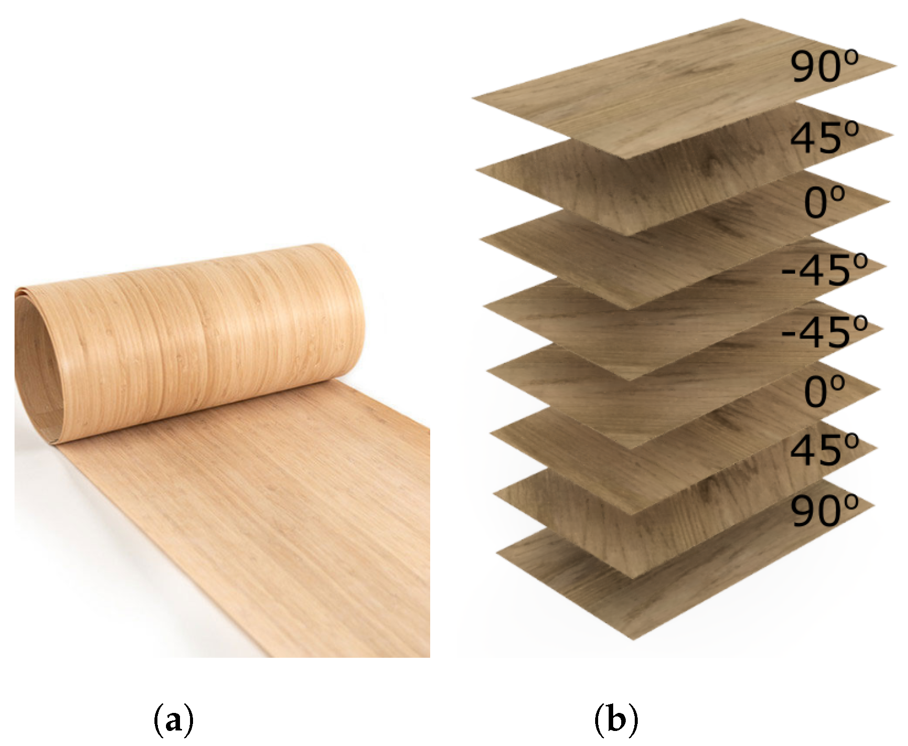
The test specimens were made from rotary-cut European Beech (Fagus sylvatica) veneers. European Beech is one of the most popular species of hardwood in Europe with a high density of 720 , good abrasion resistance, and wear properties [13]. The investigated veneers came in rolls of 200 mm × 5000 mm × 0.6 mm (width × length × thickness), supplied by Metz & Co, Stuttgart, Germany, similar to the roll shown in Figure 1a.

Figure 1.
(a) Single wood veneer roll stacked up in (b) quasi−isotropic [90/45/0/−45]s laminates for their assessment of impact resistance.
Quasi-isotropic [90/45/0/−45]s veneer laminates illustrated in Figure 1b were manufactured by stacking up individual veneer plies with different grain orientations. The adhesive PURBOND HB S109 [14] was applied to each ply with a glue spread of 90–100 g/m2 before consolidating the laminate in a hydraulic press. The laminates were uniformly pressed at 1 MPa for 20 h to ensure complete curing of the adhesive and to remove press time as a potential variable affecting the mechanical behavior. Table 1 shows the recommended manufacturing procedure for veneers using PURBOND HB S109. It should be noted that, while we followed the majority of these recommended parameters, we did not control air humidity and temperature levels since manufacturing was carried out under laboratory conditions where these parameters can fluctuate. After curing, the laminate moisture content was measured (with a PROTIMETER SurveyMaster BLD5365) and test specimens were cut to size using a Makita DXT miter saw with a 1 mm thick disk. The average thickness of these laminates after manufacturing was 4.37 mm. The moisture content of the laminates is approximately 8%–12% [15].

Table 1.
Cure properties for PURBOND HB S109 [14,15].
The quasi-isotropic layup with grain orientations of 0°, 90°, and ±45° is chosen to withstand multi-axial load cases typically observed in transport applications. Furthermore, the use of different grain orientations reduces the variations in mechanical properties.
3. Mechanical Testing & Analyses
The impact resistance of the described quasi-isotropic wood veneer laminates was tested and analyzed. We will compare results obtained from QSI and LVI tests to identify similarities and differences in the material response under static and dynamic load conditions. Due to the absence of standardized dynamic tests for wooden materials, test standards for FRP composites have been adopted. Please note that there are only standardized static (indentation) tests for wooden materials available [16]. It should be further noted that the two standardized test setups and sample geometries derived from FRP composites are not identical.
3.1. Static Indentation
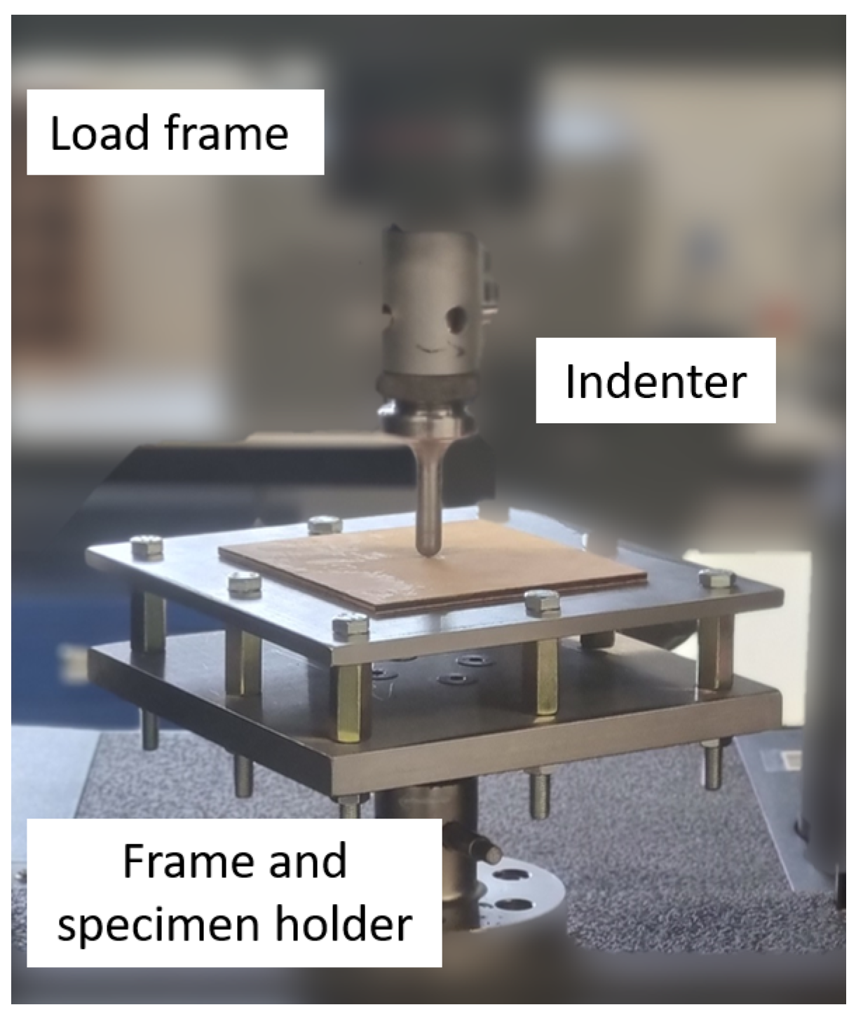
QSI tests were carried out according to the ASTM standard D6264/D6264M-17 for the determination of damage resistance in FRP composites subjected to quasi-static loading. Figure 2 shows the test setup with a 150 mm × 150 mm wood veneer plate being indented while placed on top of a rigid support frame. This frame contains a circular cut-out with a 125 mm diameter to enable plate bending. We applied a cross-head displacement rate of 1 mm/min to the hemispherical indenter (diameter: 12.7 mm) using a 10 kN Instron universal testing machine. The applied displacement and resulting loads from the test machine were recorded. Please note that clamping of the specimen to the support frame is not required according to ASTM D6264/D6264M-17.

Figure 2.
Experimental setup for Quasi-Static Indentation (QSI) tests of [90/45/0/−45]s Beech veneer laminates.
First, QSI tests were performed until complete perforation to identify the maximum indenter displacement at ultimate failure. We then conducted a series of QSI tests up to 40%, 60%, and 80% of the maximum indenter displacement to provide insight into the evolution of damage processes during indentation. Each of these tests was repeated five times. The tests were video-recorded to analyze the displacement of the indenter tip. The dissipated energy during indentation was calculated by evaluating the area under each force vs. displacement curve.
3.2. Dynamic Drop Weight Impact
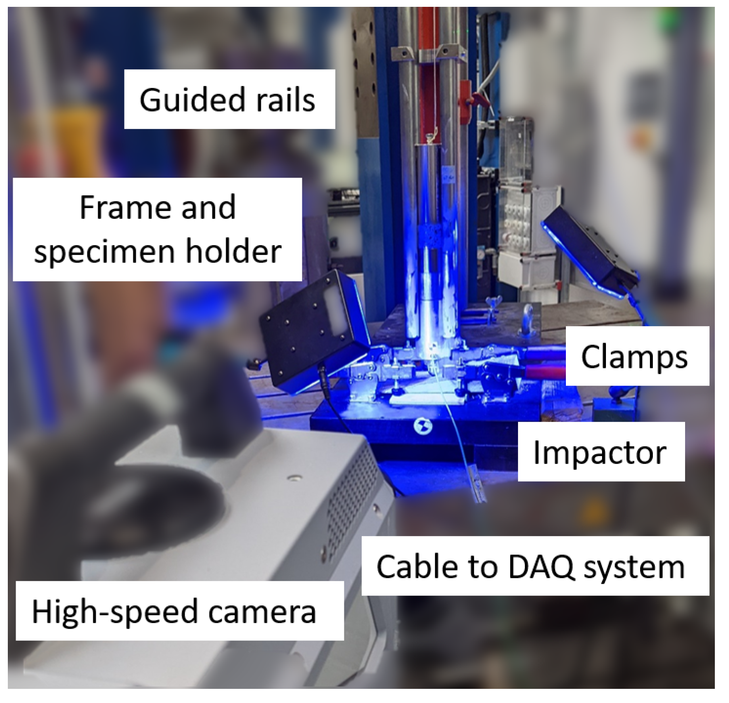
The LVI testing follows the ASTM standard D7136 developed for FRP composites. Figure 3 shows the experimental setup where the 100 mm × 150 mm test samples were impacted with a hemispherical indenter (diameter: 16 mm) guided by rails. Weights were attached to the impactor which can be released from a certain height depending on the target impact energy. The test samples were simply supported and lightly restrained to the specimen holder using four rubber-tipped clamps. The specimen holder contains a 127 mm × 76 mm rectangular cut-out. Multiple impacts were prevented by catching the impactor after the first impact. The dynamic displacement and velocity of the impactor were measured by a high-speed camera (FASTCAM SA-Z type 2100K-M-16 GB with 300,000 frames per second). A force transducer embedded in the impactor recorded the dynamic impact force and was connected to a Data Acquisition (DAQ) system to synchronize displacement and force measurements.

Figure 3.
Experimental setup for Low-Velocity Impact (LVI) tests of [90/45/0/−45]s Beech veneer laminates.
As shown in Table 2, three different impact energies were analyzed by varying the drop weight (0.3 kg to 1.8 kg) while maintaining a constant drop height of mm. Theoretically, the initial velocity at impact is m/s for all tests. We measured an average velocity of 2.0 m/s. The reduction is mainly caused by friction between the guided rails and the impactor. To directly compare equivalent results from quasi-static and dynamic tests, the dissipated energy during impact was calculated in the same manner as mentioned above by integrating each force vs. displacement curve.
Table 2.
Dynamic impact testing of [90/45/0/−45]s Beech veneer laminates with varying impact energies.
3.3. Post-Testing Analyses
Various analysis techniques during and after testing were applied to gain more insight into the material behavior of the quasi-isotropic [90/45/0/−45]s Beech veneer laminates subjected to QSI and LVI loadings.
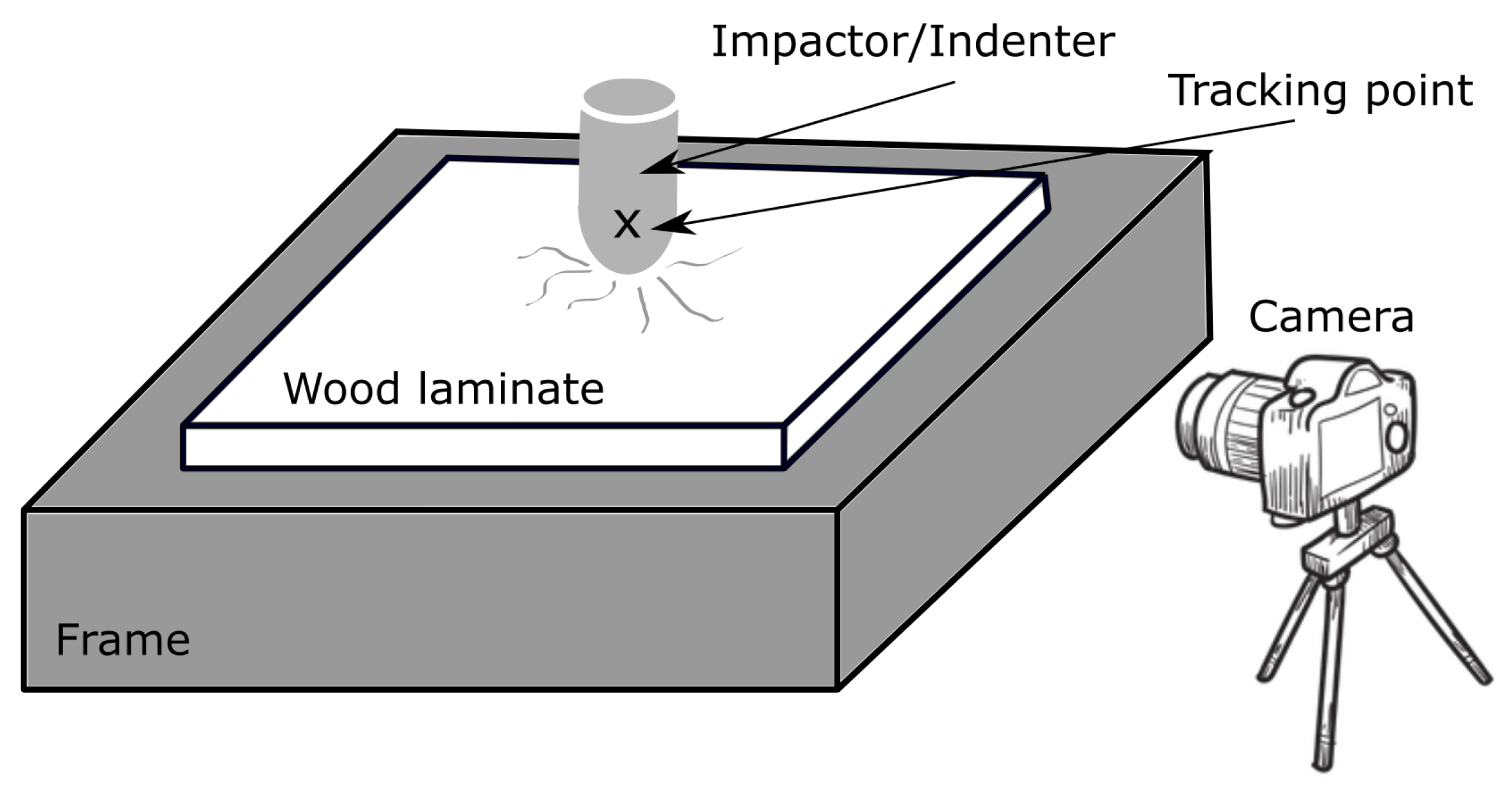
To avoid any influence of machine compliance and to enable a consistent comparison between QSI and LVI tests, we tracked the movement of the indenter/impactor as illustrated in Figure 4. The resulting displacements were synchronized with the measured indentation/impact force. The QSI tests were recorded with a mobile phone while the LVI required the use of high-speed cameras as outlined above.

Figure 4.
Illustration of tracking the impactor/indenter to obtain its displacement during testing.
Composites generally exhibit permanent deformations after indentation/impact which can be visually observed by the presence of a dent and bulge on the upper and lower surface of the test samples [17,18]. We measured the dent of the surface of test samples with a 5X lens on an Alicona microscope to investigate whether the static and dynamic loading induces different permanent deformations on the top surface of the laminates.
Furthermore, we conducted destructive cross-sectional analyses by cutting the samples after testing through the location of indentation/impact. The inspection of these cross-sectional cuts with an Olympus SZ61 optical microscope revealed various failure modes through the thickness of the test samples.
4. Results
The results of the two tests (static and dynamic) will be presented quantifying the overall force vs. displacement behavior as well as permanent deformation and damage sequences. To identify similarities and differences, these results are then compared.
4.1. Quasi-Static Indentation Tests
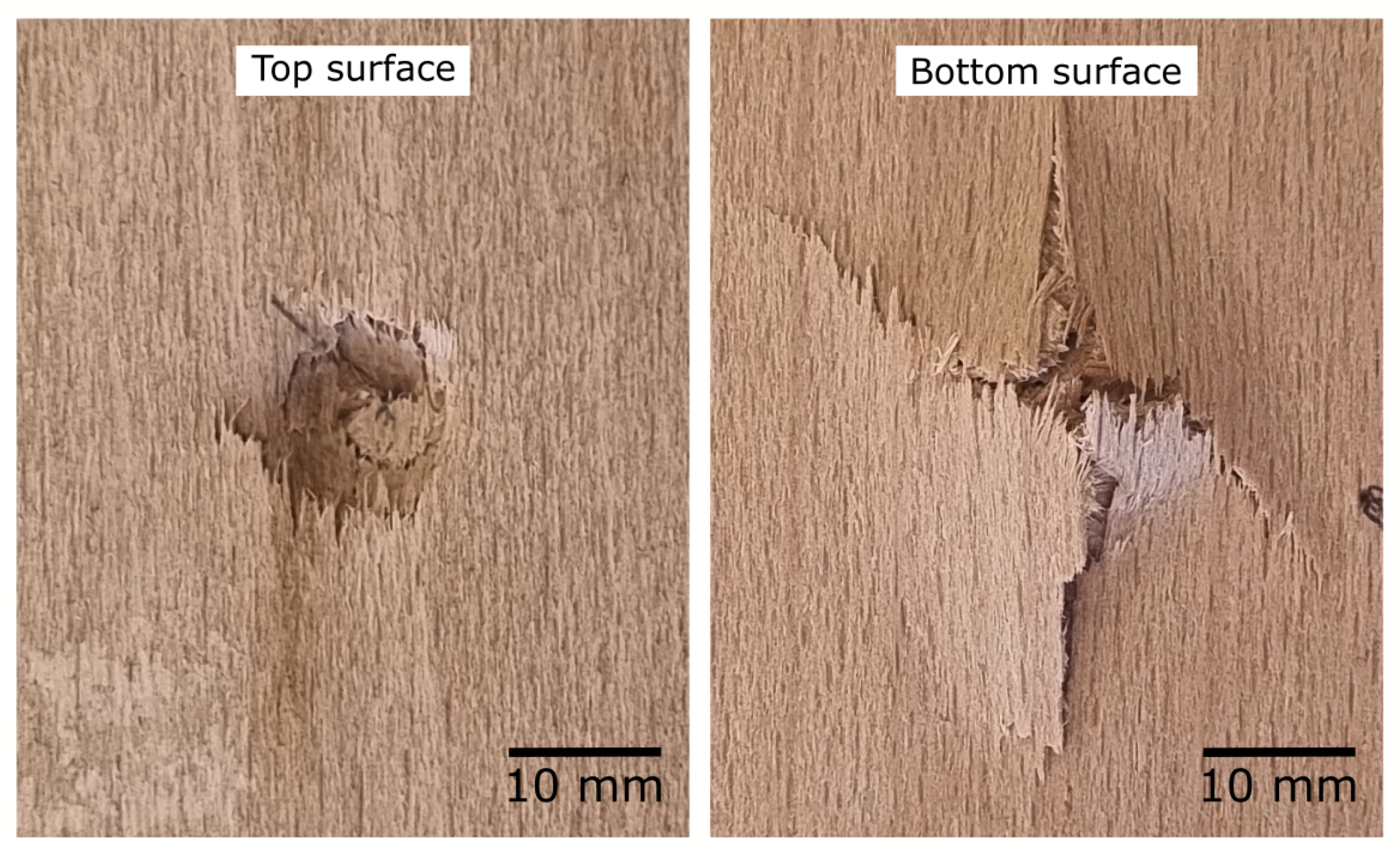
Figure 5 shows the top and bottom surfaces of a completely perforated QSI test sample, respectively. While the shape of the hemispherical indenter (diameter: 12.7 mm) is clearly visible on the top surface due to distinct compressive failure, the bottom surface exhibits more complex failure modes with interacting tensile cracks in various orientations. Based on the maximum displacement at the perforation, we conducted a series of interrupted QSI tests.

Figure 5.
Inspection of top and bottom surfaces after completely perforated Quasi-Static Indentation (QSI) test of [90/45/0/−45]s Beech veneer laminates.
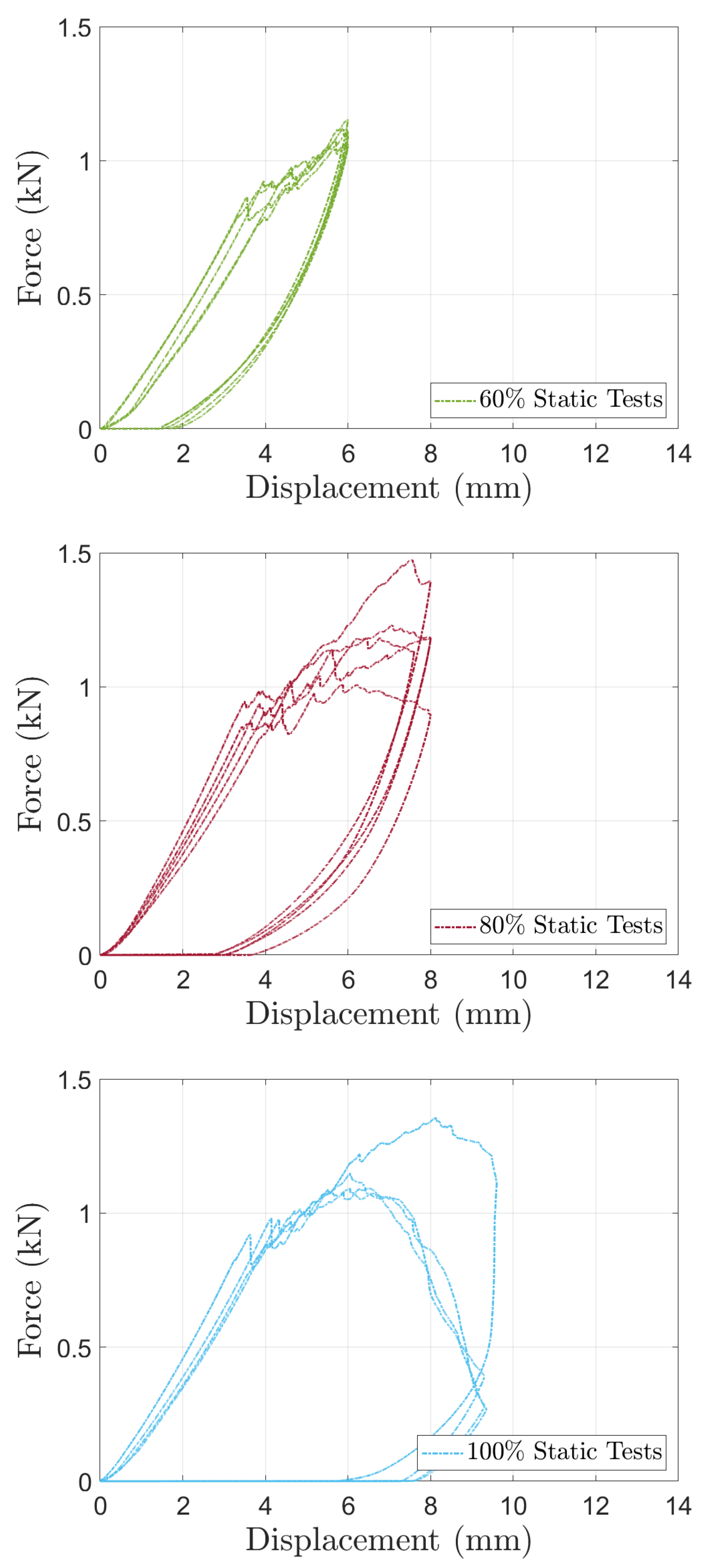
The resulting force vs. displacement curves of these QSI tests (5 samples for each interrupted test at 40%–100% in increments of 20%) are shown in Figure 6. It can be seen that all tests yield an approximate bi-linear behavior with a consistent kink at about 0.8–1.0 kN. In addition, all test samples exhibited permanent deformation after QSI with unloading curves not returning to the origin of the force vs. displacement graph. The consistent kink and the presence of significant permanent deformation indicate that plasticity is one of the governing failure modes in QSI tests. If tensile failure modes were dominant, more severe load drops and a distinct maximum indentation force would be expected due to the brittle nature of these modes as observed in FRP composites [17]. The curves in Figure 6 will be further analyzed in Section 4.3 when directly comparing results obtained from QSI and LVI tests. Overall, the force vs. displacement curves in Figure 6 are very consistent, indicating good repeatability of the QSI tests. This indicates good quality veneers combined with a reliable and consistent manufacturing process.
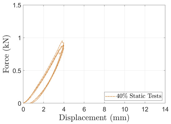
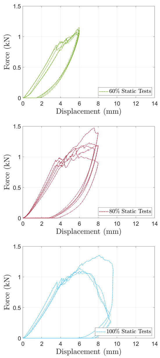
Figure 6.
Force vs. displacement results of interrupted Quasi-Static Indentation (QSI) tests.
By calculating the area under each force vs. displacement curve shown in Figure 6, the dissipated energy during QSI tests can be evaluated. Table 3 shows the average values of dissipated energy for each QSI test alongside the coefficients of variation (CoV). As expected, the dissipated energy increases with a larger indentation depth (displacement). The CoV value of 13.3% for the 100% QSI tests is larger compared to the interrupted counterparts. This can also be seen in the force vs. displacement curves in Figure 6 where the 100% QSI tests show larger variations. These larger discrepancies are additional indicators that many interacting (tensile) failure modes only contribute to energy absorption toward complete perforation while the majority of energy until then is dissipated by plastic deformation. The cross-sectional failure analyses later on will further examine the evolution of failure modes.
Table 3.
Average dissipated energy (in kJ/m2) and coefficient of variation (in brackets) based on force vs. displacement curves of different static indentation tests shown in Figure 6.
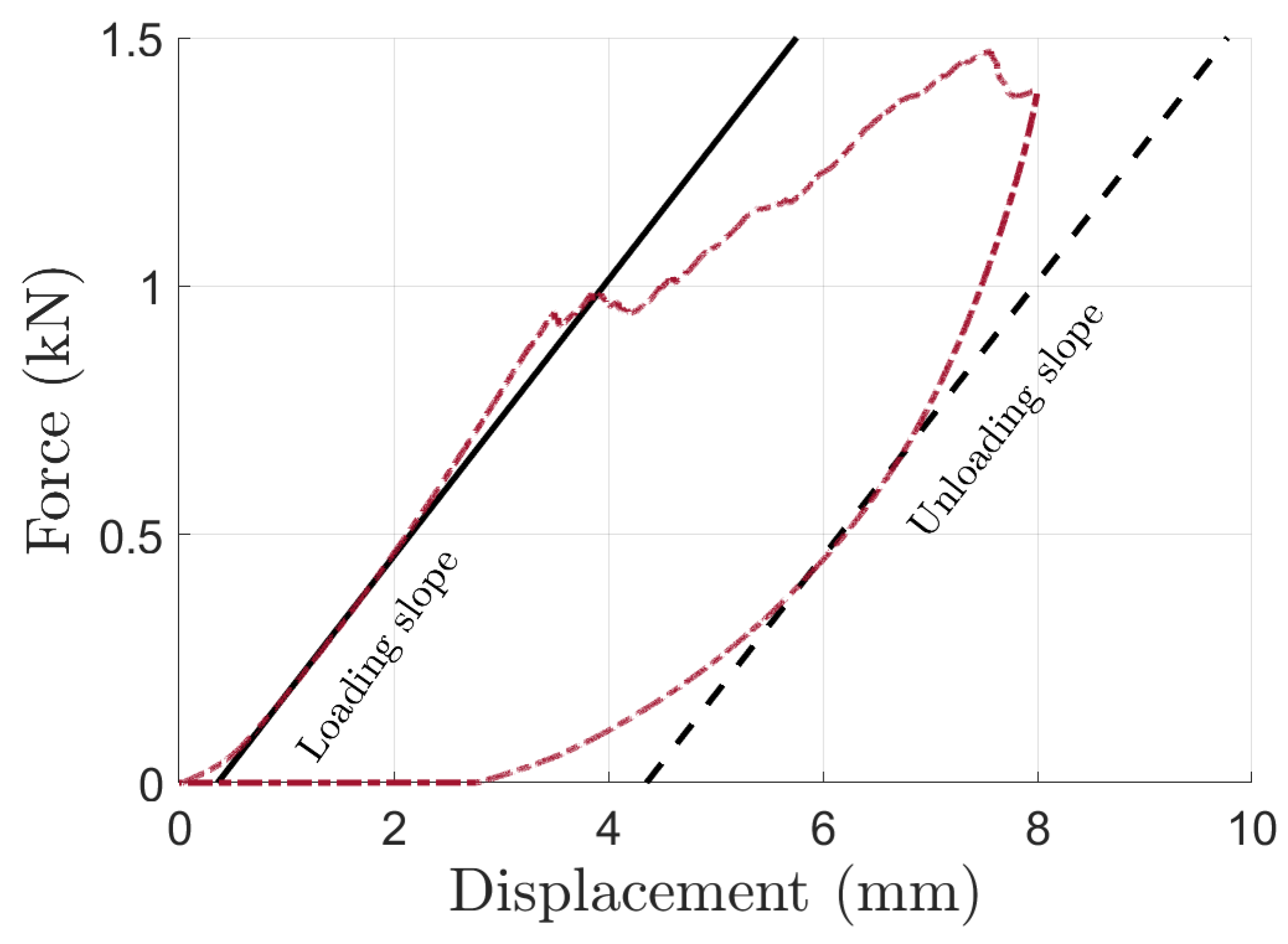
If plasticity is indeed the major mechanism for energy absorption, it is expected that the slope of the force vs. displacement graphs during loading and unloading should be similar. Figure 7 illustrates the measurement of these slopes. Please note that the graphs during unloading are nonlinear, making it difficult to perform a linear fit through the data. Table 4 lists the results of these slope measurements. It can be seen that the slopes during loading and unloading are comparable, indicating that the wood veneers deform plastically during the QSI tests.
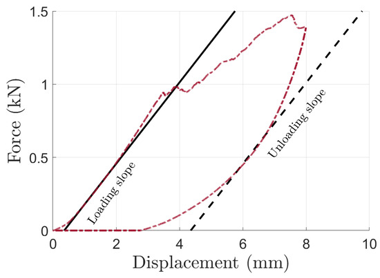
Figure 7.
Illustration of slopes measurements during loading and unloading in Quasi-Static Indentation (QSI) tests of wood veneer laminates.
Table 4.
The average slope (in kN/mm) and coefficient of variation (in brackets) obtained from measurements in QSI tests of wood veneer laminates illustrated in Figure 7.
Figure 8 shows representative surface measurements of each interrupted QSI test to quantify the permanent deformation caused by the quasi-static indentation. Please note that the surfaces after 100% QSI tests are completely perforated as shown in Figure 5, therefore a surface analysis of these test samples is not meaningful. The maximum permanent deformation of the 40%, 60%, and 80% QSI tests in Figure 8 are approximately 0.4 mm, 0.6 mm, and 1.4 mm, respectively. These measurements can be compared to the corresponding values immediately after QSI in the force vs. displacement curves in Figure 6 where the unloading curves intercept the x-axis. It can be seen that the 40%, 60% and 80% QSI tests yield around 0.5 mm, 1.8 mm, and 3.5 mm of permanent deformation immediately after QSI, respectively. The differences between the measured deformations from the force vs. displacement curves (immediately after testing) and from the surface analysis can be explained by the viscoelastic and viscoplastic behavior of wood. Springback is a well-known mechanism in the viscoplastic behavior of wood where thickness is recovered over time after the release of compressive loads. It can be seen that the permanent deformation from the surface analysis is similar for the 40% and 60% QSI tests. In contrast, the 80% QSI tests result in significantly larger deformations. This is another indication that failure modes other than plasticity do not influence the structural response in QSI tests until 80%–100% of the ultimate displacement at perforation.
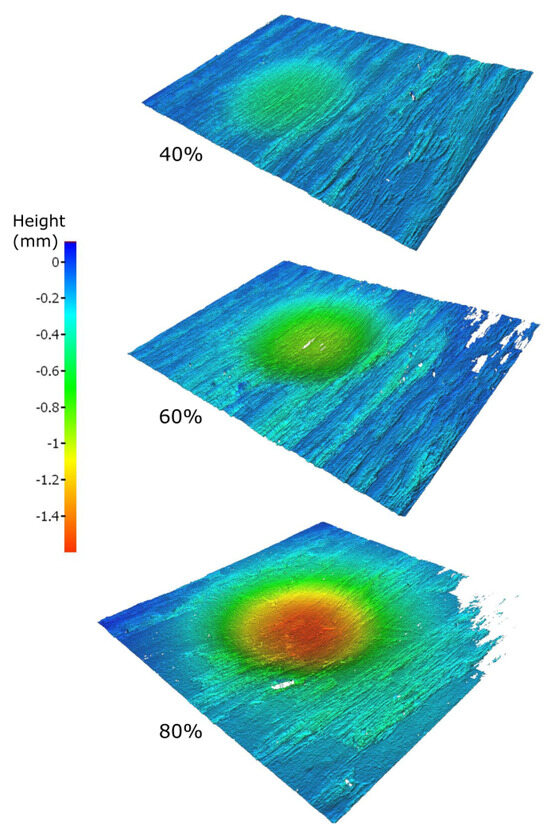
Figure 8.
Surface analysis to measure permanent deformation after Quasi−Static Indentation (QSI) tests of [90/45/0/−45]s Beech veneer laminates.
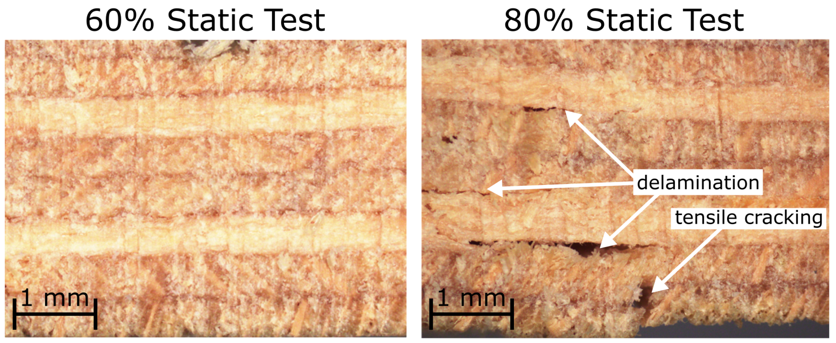
The results of the destructive cross-sectional microscopy analysis are shown in Figure 9. The cross-section around the indentation location of a 60% QSI test does not show any obvious cracks. The same observation was made in test samples after 40% QSI tests. In contrast, the cross-sectional cut of a test sample after 80% QSI testing shown in Figure 9 reveals various locations of delamination and the presence of tensile-induced cracks toward the bottom surface. These findings confirm the previous observations that plasticity in compression is the governing failure mode in QSI tests of Beech veneer laminates as hypothesized based on (i) the shapes of the force vs. displacement curves in Figure 6 and (ii) the presence of permanent deformations with respect to energy dissipation and surface analyses.

Figure 9.
Cross-section microscopy to identify failure modes after Quasi-Static Indentation (QSI) tests of [90/45/0/−45]s Beech veneer laminates.
4.2. Dynamic Impact Tests
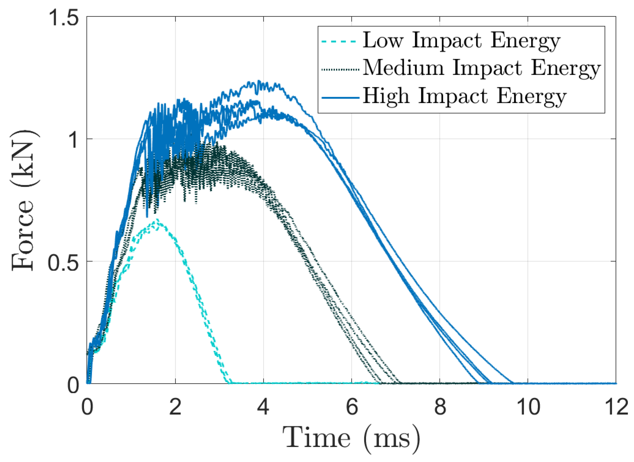
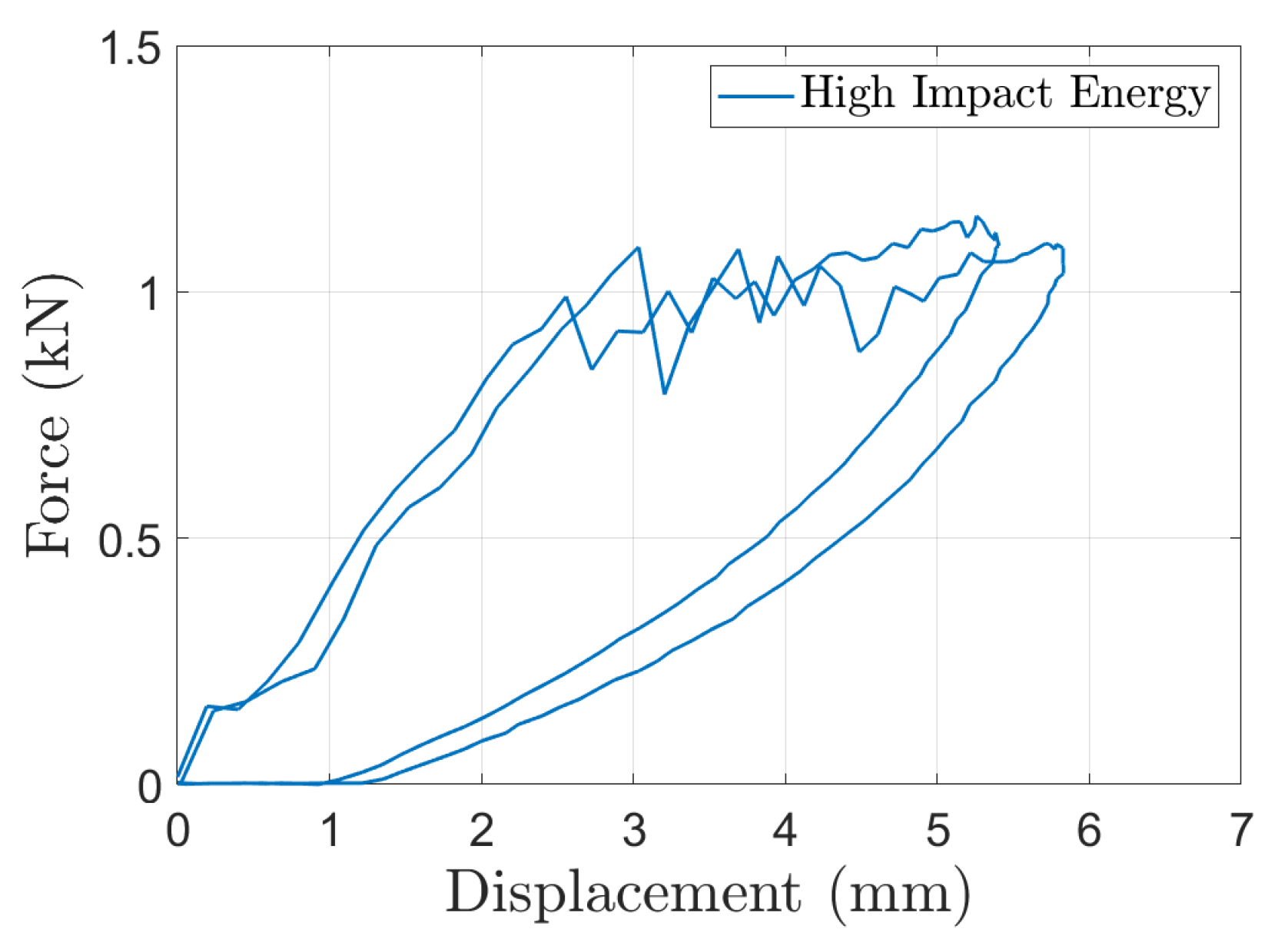
Figure 10 shows the force vs. time results from the LVI tests that are directly measured with the transducer embedded in the impactor. Despite the increased complexity in test equipment, measurement, and analysis, the three LVI test results of each LVI impact energy show a high level of consistency, similar to the results presented from QSI tests in Figure 6. To enable a direct comparison between QSI and LVI results, Figure 11 plots these impact forces vs. the displacement of the impactor measured by the high-speed camera. The force vs. displacement curves show, again, a bi-linear behavior with a kink at similar force levels at 0.8 to 1.0 kN as observed in QSI tests. In the direct comparison between these two tests in Section 4.3, we will investigate the link between the different LVI impact energies and the corresponding interrupted QSI test.

Figure 10.
Force vs. time results of dynamic Low-Velocity Impact (LVI) tests of [90/45/0/−45]s Beech veneer laminates.


Figure 11.
Force vs. displacement results of dynamic Low-Velocity Impact (LVI) tests of [90/45/0/−45]s Beech veneer laminates.
The calculation of the area under each force vs. displacement curve in Figure 11 reveals the dissipated energy during dynamic impact. Table 5 lists the average dissipated energies for the low, medium, and high impact cases, respectively. It can be seen that the low energy case only dissipates a small amount of energy of 0.13 kJ/m2 as the force vs. displacement curves do not reach the critical kink point of around 0.8 to 1.0 kN, and hence predominantly elastic deformation can be considered here. The other two impact cases (medium/high) will be compared to QSI results in Section 4.3.
Table 5.
Average dissipated energy (in kJ/m2) and coefficient of variation (in brackets) based on force vs. displacement curves of different dynamic impact tests shown in Figure 11.
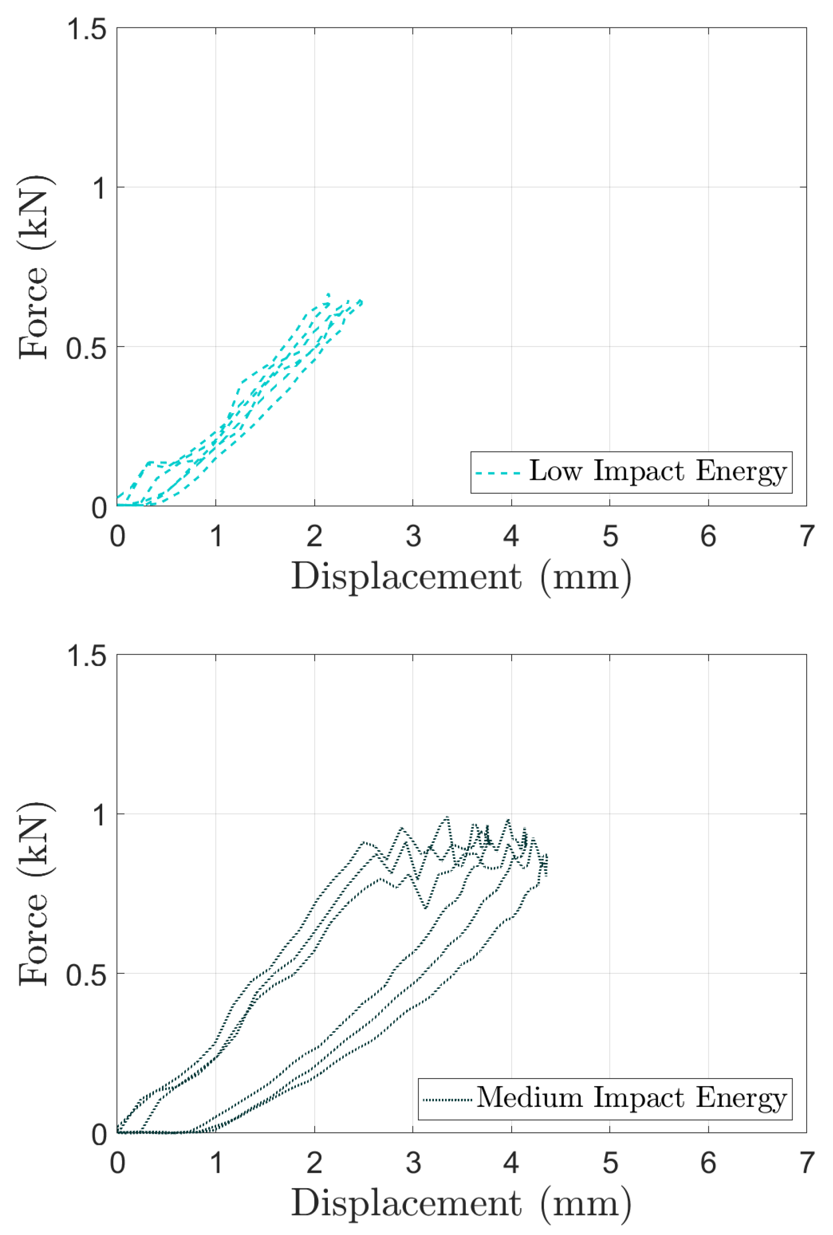
Similar to the slope analysis of the QSI tests shown in Figure 7, Table 6 presents the slope measurements during loading and unloading in the dynamic impact tests. First, it can be seen that the loading slope increases with increasing impact energies, suggesting strain-rate sensitive responses of the wood veneer laminates. Second, the unloading slope remains unchanged from its corresponding linear measure, implying that plasticity is the major energy-absorbing mechanism during LVI tests.
Table 6.
The average slope (in kN/mm) and coefficient of variation (in brackets) obtained from measurements in LVI tests of wood veneer laminates illustrated in Figure 7.
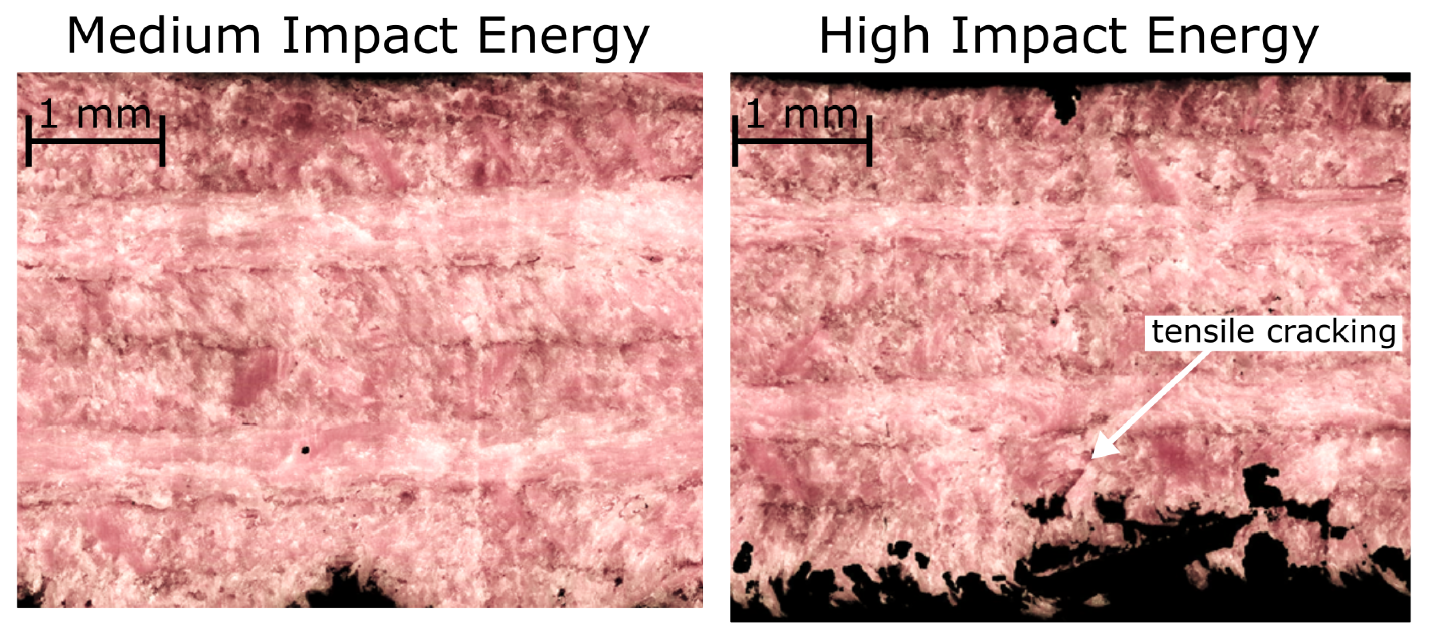
The results from the cross-sectional microscopy after a medium and high energy impact are shown in Figure 12. Please note that the low energy impact case is omitted due to the dominant elastic behavior. No obvious cracks can be observed in the two cross-sectional cuts in Figure 12. The high energy impact analysis shows the onset of tensile cracks close to the bottom surface away from the location of the impactor.

Figure 12.
Cross-section microscopy to identify failure modes after dynamic Low-Velocity Impact (LVI) tests of [90/45/0/−45]s Beech veneer laminates.
4.3. Comparison of Results
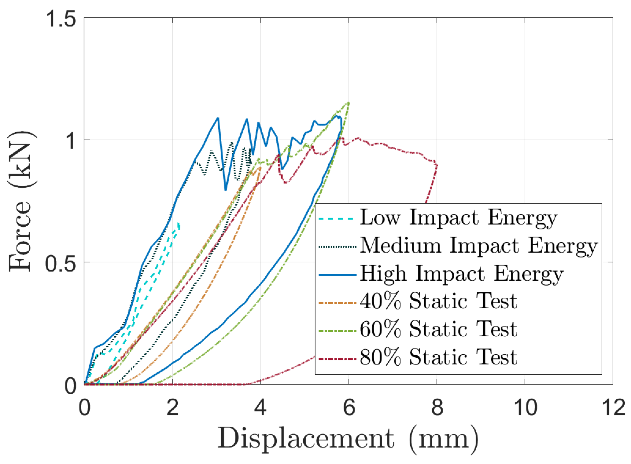
As one of the main objectives is to understand the interchangeability between QSI and LVI tests for wood veneer laminates, Figure 13 directly compares representative force vs. displacement curves from the two tests. The comparison shows that the initial stiffness from the static and dynamic tests differs (influenced by different boundary conditions of the two tests) while the maximum force level at around 1 kN is consistent.
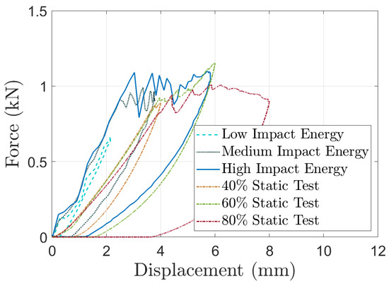
Figure 13.
Comparison of force vs. displacement curves from quasi-static and dynamic impact tests of [90/45/0/−45]s Beech veneer laminates.
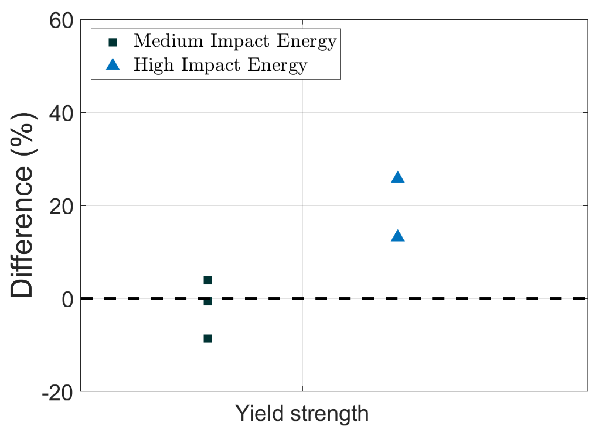
To achieve a quantitative comparison between the two tests, we distinguish the force vs. displacement curves into an elastic and a nonlinear regime as depicted in Figure 14. The evaluation of the slope in the elastic regimen shown in Table 4 reveals that the static tests result in a stiffness of 0.23 kN/mm (±8%). Due to the different boundary conditions of the two ASTM standards for static and dynamic testing, a direct quantitative comparison of the resulting slopes is not possible. However, Table 6 shows that the stiffness from dynamic tests of around 0.36 kN/mm (±9%) increases with increasing impact energy. The onset of the nonlinear regime can be classified as the yield strength. The force vs. displacement curves in Figure 13 do not show obvious differences in yield strength between QSI and LVI tests. The quasi-static tests reveal a strength of 0.88 kN (±7%) while the dynamic LVI tests result in an average yield strength of 0.93 kN (±10%). This is also visualized in the normalized plot with respect to the QSI impact strength in Figure 15 with a slight increase in yield strength for wood veneers subjected to higher impact energies.

Figure 14.
Illustration of elastic and nonlinear regimes in force vs. displacement curves to quantify the comparison between static and dynamic impact test results.

Figure 15.
Comparison of yield strength between different dynamic impact tests normalized with respect to the equivalent values obtained from quasi−static indentation tests.
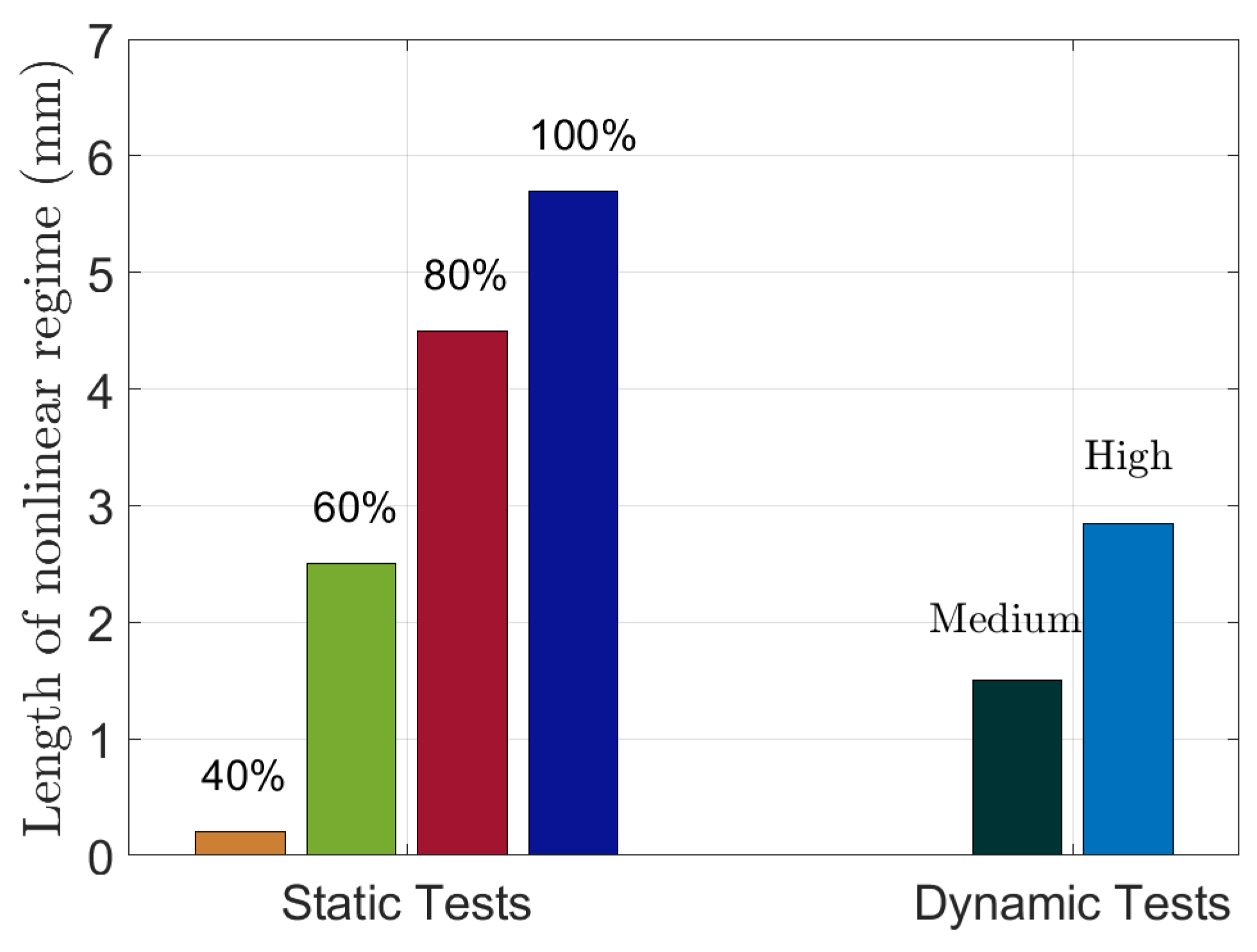
The nonlinear regime is assessed with respect to its slope and length. Please note that the 40% QSI tests and the LVI tests with low impact energy did not enter the nonlinear regime, hence no results on these tests are presented here. Table 7 lists the average slopes of the nonlinear regime measured from three QSI tests (60%, 80%, and 100%) and two LVI tests (medium and high impact energies). The results show that the slope in the nonlinear regime from static tests is significantly larger (0.13 kN/mm) compared to dynamic counterparts (0.05 kN/mm). The length of the nonlinear regime from different tests is shown in Figure 16. These length measurements indicate that energy dissipation (due to plastic deformation and/or damage) caused in the medium dynamic impact test is equivalent to a ≈50% QSI test whereas the high energy impact test is comparable to a 60%–70% QSI test. This finding aligns well with the cross-sectional analyses in Figure 8 and Figure 12. The medium impact and the 60% QSI test samples did not show any obvious failure. The high dynamic impact energy caused some visible tensile cracks but significantly less damage compared to the 80% QSI test. Furthermore, these results agree with the analyses of dissipated energies in static (Table 3) and dynamic (Table 5) test cases where the medium and high dynamic tests yield lower and higher equivalent dissipated energy values compared to the results obtained from 60% QSI tests, respectively.
Table 7.
Average values of slope (kN/mm) in nonlinear regime from quasi-static and dynamic impact tests based on Figure 14.
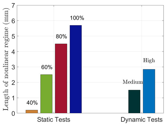
Figure 16.
Comparison of the length of the nonlinear regime from quasi-static and dynamic impact tests on [90/45/0/−45]s Beech veneer laminates based on Figure 14.
5. Discussion
The consistent test results of the investigated thin-walled, quasi-isotropic wood veneer laminates subjected to static and dynamic impact loads confirm findings from previous studies [6] where the authors observed deviations of less than 10% in laminates under pure tensile loads. Here, the results indicate, in both static and dynamic cases, that plasticity in compression is the dominant energy-absorbing mechanism during impact. Figure 9 and Figure 12 show the late development of tensile cracks in 80% QSI and high-impact energy tests, respectively. Such late onset of tensile cracking is an advantageous characteristic of the wood veneer laminates, making them impact-resistant with good residual load-carrying capabilities. Unlike FRP composites under impact loads, the evolution of delamination is not a concern within the wood veneer laminates. Therefore, these laminates can withstand low-velocity impacts, for example during maintenance and service of wood laminates in future transport applications such as tool drop or the impact of debris and rocks. Of course, it is essential to conduct comprehensive investigations into other mechanical properties, such as creep and relaxation, before drawing conclusions regarding the advantageous impact behavior of wood veneer laminates.
As shown in Figure 2 and Figure 3, the setup of the QSI and LVI tests is vastly different. The quasi-static tests can be conducted only using an indenter and specimen holder with a standardized test machine. In contrast, the dynamic impact tests additionally require the use of a (non-) standardized drop tower in combination with high-speed cameras. The following sections will discuss the similarities and differences resulting from these two tests with the goal of determining whether the results obtained from QSI and LVI tests are interchangeable. Please note that the influence of indenter/impactor diameter, sample size, and clamping are neglected here to comply with the corresponding ASTM standards.
5.1. Similarities between Static and Dynamic Impact
The comparison of test results in Section 4.3 reveals that most of the damage measurements after QSI and LVI tests are similar. Figure 15 shows that the measured yield strength values obtained from the static and dynamic tests only differ by up to 5%. Furthermore, the evolution of damage is consistent as observed in the cross-sectional analyses in Figure 9 and Figure 12. Plasticity is identified as the dominant energy-absorbing mechanism with tensile cracks developing at larger indentation/impact depths. Consequently, energy absorption measured from QSI and LVI tests in Table 3 and Table 5, respectively, align well considering that medium impact tests are comparable to 50% QSI counterparts while high impact tests are equivalent to 60%–70% QSI tests.
5.2. Differences between Static and Dynamic Impact
The force vs. displacement curves from representative static and dynamic tests in Figure 13 show that the initial stiffness vastly differs between the two tests with differences of up to 80%. While a direct comparison of these values is limited due to different boundary conditions, the results from the dynamic loading shown in Table 6 show an increasingly stiffer impact response with increasing impact energies. This indicates that the elastic response of the Beech veneer laminates is strain-rate sensitive. This finding is supported by the results obtained from Pang et al. [12] who found that compressive properties of Beechwood are dependent on the strain rate. Similarly, Table 7 shows that the slope of the nonlinear regime varies between static and dynamic testing. With plasticity being the major absorbing mechanism, these findings indicate that plastic hardening is also strain-rate sensitive. It should be noted that more oscillations are observed in the nonlinear regime in dynamic tests (see Figure 13) compared to equivalent static measurements. Unlike QSI tests, the presence of oscillations in force measurements is typical during LVI tests [8]. The simple setup and the absence of oscillations in QSI testing motivate exploring whether static and dynamic tests of wood veneer laminates are interchangeable.
5.3. Interchangeability of Static and Dynamic Tests
Based on the discussed similarities and differences, it can be concluded that QSI and LVI tests of Beech veneer laminates are interchangeable if damage and energy absorption are of interest. However, the findings on the stiffness measurements and related strain-rate effects in dynamic tests do not permit the general interchangeability of the two tests. The strain-rate insensitivity of damage and energy absorption will facilitate the development of efficient finite element simulations [19] to virtually design wood-based components for future transport applications as static damage properties can be used to simulate the dynamic evolution of progressive damage. Nonetheless, dynamic tests will be needed for model validation due to the strain-rate sensitivity during elastic bending of the investigated wood veneer laminates.
5.4. Comparison to Carbon Fiber-Reinforced Laminates
Due to the lack of standardized impact tests of wood veneer laminates, the QSI and LVI tests were adopted from ASTM standards D6264 and D7136 designed for FRP composites. Hence, the presented results can be directly compared with equivalent studies on Carbon Fiber Reinforced Polymers (CFRPs) [17,20]. Sun and Hallett [17] investigated 4 mm thick, quasi-isotropic CFRP laminates subjected to LVI tests. Delamination between CFRP plies was reported as the major failure mode in tests with impact energies of 6–8 J. Maximum impact forces of around 5 kN were measured. The results of the LVI tests on wood veneer laminates in Figure 10 can be directly compared to these findings with an identical quasi-isotropic layup and comparable thickness. The LVI tests yield a maximum force of around 1.2 kN for the high-impact energy case (nominal impact energy of 5 J). As expected, CFRP outperforms the wood laminates with respect to maximum impact forces. However, it should be noted that, unlike in CFRPs, the majority of energy in wood laminates subjected to impact loads is absorbed by plastic deformation. As delamination caused by the impact may not be visible in CFRPs with the susceptibility to unstable crack propagation [18], plasticity in impacted wood laminates is a more favorable mechanism potentially leading to more consistent and controllable residual mechanical properties after impact. Future research will investigate the residual load-carrying capabilities of wood veneer laminates, for example in compression-after-impact tests.
6. Conclusions
This paper compares the static and dynamic impact response of thin-walled, quasi-isotropic Beech wood veneer laminates subjected to Quasi-Static Indentation (QSI) and Low-Velocity Impact (LVI) tests. The simplified setup and analysis of QSI tests make it desirable to interchange the findings of the two tests. It is found that post-peak behavior such as yield strength and damage evolution are interchangeable while LVI tests show that the elastic stiffness is strain-rate sensitive. In both test cases, plasticity is identified as the major energy-absorbing mechanism. These findings are important for the incorporation of sustainable wood veneer laminates into the design of impact-resistant structures in future transport applications.
Author Contributions
Conceptualization, J.R., T.F., M.W., M.J. and M.S.; methodology, J.R., Y.G.I. and M.W.; software, J.R., Y.G.I. and S.O.; formal analysis, J.R., Y.G.I. and S.O.; investigation, J.R., Y.G.I. and S.O.; resources, M.W.; data curation, J.R.; writing—original draft preparation, J.R.; writing—review and editing, T.F., M.W., M.J. and M.S.; supervision, J.R., M.J. and M.S.; All authors have read and agreed to the published version of the manuscript.
Funding
The authors would like to thank the German Academic Exchange Service (DAAD) for providing financial assistance to enable the joint work between Deakin University and the German Aerospace Center.
Data Availability Statement
The data presented in this study is available from the corresponding author upon reasonable request.
Acknowledgments
The authors would like to thank the technical staff of the School of Engineering at Deakin University and Tobias Behling from the German Aerospace Center for their support of the work.
Conflicts of Interest
The authors declare no conflicts of interest.
References
- Große, T.; Fischer, F.; Kohl, D.; Albert, T.; Boese, B.; Enge, J. Verbundprojekt: Strukturbaugruppen auf Basis Nachhaltiger Holzbasierter Materialsysteme zur Reduzierung von Masse und Umweltauswirkungen im Strassen- und Schienenfahrzeugbau; Volkswagen AG: Wolfsburg, Germany, 2020. [Google Scholar] [CrossRef]
- Brandner, R. Cross laminated timber (clt) in compression perpendicular to plane: Testing, properties, design and recommendations for harmonizing design provisions for structural timber products. Eng. Struct. 2018, 171, 944–960. [Google Scholar] [CrossRef]
- Dong, W.; Li, M.; Lee, C.-L.; MacRae, G.; Abu, A. Experimental testing of full-scale glulam frames with buckling restrained braces. Eng. Struct. 2020, 222, 111081. [Google Scholar] [CrossRef]
- As, N.; Goker, Y.; Dundar, T. Effect of knots on the physical and mechanical properties of scots pine (Pinus sylvestris L.). Wood Res. 2006, 51, 51–58. [Google Scholar]
- Fernando, D.; Frangi, A.; Kobel, P. Behaviour of basalt fibre reinforced polymer strengthened timber laminates under tensile loading. Eng. Struct. 2016, 117, 437–456. [Google Scholar] [CrossRef]
- Reiner, J.; Pizarro, S.O.; Hadi, K.; Narain, D.; Zhang, P.; Jennings, M.; Subhani, M. Damage resistance and open-hole strength of thin veneer laminates: Adopting design and testing principles from fibre-reinforced polymers. Eng. Fail. Anal. 2023, 143, 106880. [Google Scholar] [CrossRef]
- Bull, D.; Spearing, S.; Sinclair, I. Investigation of the response to low velocity impact and quasi-static indentation loading of particle-toughened carbon-fibre composite materials. Compos. Part A Appl. Sci. Manuf. 2015, 74, 38–46. [Google Scholar] [CrossRef]
- Spronk, S.; Kersemans, M.; Baerdemaeker, J.; Gilabert, F.; Sevenois, R.; Garoz, D.; Kassapoglou, C.; Van Paepegem, W. Comparing damage from low-velocity impact and quasi-static indentation in automotive carbon/epoxy and glass/polyamide-6 laminates. Polym. Test. 2018, 65, 231–241. [Google Scholar] [CrossRef]
- Castellano, A.; Fraddosio, A.; Piccioni, M.D. Quantitative analysis of qsi and lvi damage in gfrp unidirectional composite laminates by a new ultrasonic approach. Compos. Part B Eng. 2018, 151, 106–117. [Google Scholar] [CrossRef]
- Toson, B.; Viot, P.; Pesqué, J. Finite element modeling of balsa wood structures under severe loadings. Eng. Struct. 2014, 70, 36–52. [Google Scholar] [CrossRef]
- Fothe, T.; Azeufack, U.G.; Kenmeugne, B.; Fogue, M. A one-dimensional elasto-viscoplastic model coupled to damage for the description of creep in wooden materials. J. Wood Sci. 2022, 68, 8. [Google Scholar] [CrossRef]
- Pang, S.; Liang, Y.; Tao, W.; Liu, Y.; Huan, S.; Qin, H. Effect of the strain rate and fiber direction on the dynamic mechanical properties of beech wood. Forests 2019, 10, 881. [Google Scholar] [CrossRef]
- Jahres, D.B.; Baum, D. Die buche—Baum des jahres 2020. Available online: https://www.waldwissen.net/en/forest-ecology/forest-plants/deciduous/the-beech-tree-of-the-year-2022 (accessed on 13 January 2024).
- Henkel. Purbond HB S109 Single-Component Polyurethane Adhesive for the Manufacture of Engineered Wood Products; Techical Report; Henkel: Düsseldorf, Germany, 2013. [Google Scholar]
- Orellana, S.; Hadi, K.; Narain, D.; Jennings, M.; Subhani, M.; Reiner, J. Effects of manufacturing parameters on mechanical interface properties of thin wood veneer laminates. Int. J. Adhes. Adhes. 2024, 130, 103614. [Google Scholar] [CrossRef]
- ISO 2439:2008; Flexible Cellular Polymeric Materials Determination of Hardness (Indentation Technique). International Organization for Standardization: Geneva, Switzerland, 2008. Available online: https://www.iso.org/standard/42717.html (accessed on 29 March 2024).
- Sun, X.; Hallett, S. Barely visible impact damage in scaled composite laminates: Experiments and numerical simulations. Int. J. Impact Eng. 2017, 109, 178–195. [Google Scholar] [CrossRef]
- Sun, X.; Hallett, S. Failure mechanisms and damage evolution of laminated composites under compression after impact (CAI): Experimental and numerical study. Compos. Part A Appl. Sci. Manuf. 2018, 104, 41–59. [Google Scholar] [CrossRef]
- Reiner, J.; Zobeiry, N.; Vaziri, R. Efficient finite element simulation of compression after impact behaviour in quasi-isotropic composite laminates. Compos. Commun. 2021, 28, 100967. [Google Scholar] [CrossRef]
- Chen, C.; Nesbitt, S.; Reiner, J.; Poursartip, A.; Fernlund, G. Cure path dependency of damage resistance in interlayer toughened composite laminates subjected to quasi-static indentation and low-velocity impact. Compos. Part B Eng. 2023, 266, 111000. [Google Scholar] [CrossRef]


Disclaimer/Publisher’s Note: The statements, opinions and data contained in all publications are solely those of the individual author(s) and contributor(s) and not of MDPI and/or the editor(s). MDPI and/or the editor(s) disclaim responsibility for any injury to people or property resulting from any ideas, methods, instructions or products referred to in the content. |
© 2024 by the authors. Licensee MDPI, Basel, Switzerland. This article is an open access article distributed under the terms and conditions of the Creative Commons Attribution (CC BY) license (https://creativecommons.org/licenses/by/4.0/).