Abstract
Accurate longitudinal control is crucial in autonomous driving, but inherent delays and lag in electric vehicle powertrains hinder precise control. This paper presents a two-stage design for a longitudinal speed controller to enhance speed tracking performance in autonomous electric vehicles. The first stage involves designing a Model Predictive Control (MPC) system that accounts for powertrain signal delay and response lag using a First Order Plus Dead Time (FOPDT) model integrated with the vehicle’s longitudinal dynamics. The second stage employs lookup tables for the drive motor and brake system to convert control signals into actual vehicle inputs, ensuring precise throttle/brake pedal values for the desired driving torque. The proposed controller was validated using the CarMaker simulator and real vehicle tests with a Hyundai IONIQ5. In real vehicle tests, the proposed controller achieved a mean speed error of 0.54 km/h, outperforming conventional PID and standard MPC methods that do not account for powertrain delays. It also eliminated acceleration and deceleration overshoots and demonstrated real-time performance with an average computation time of 1.32 ms.
1. Introduction
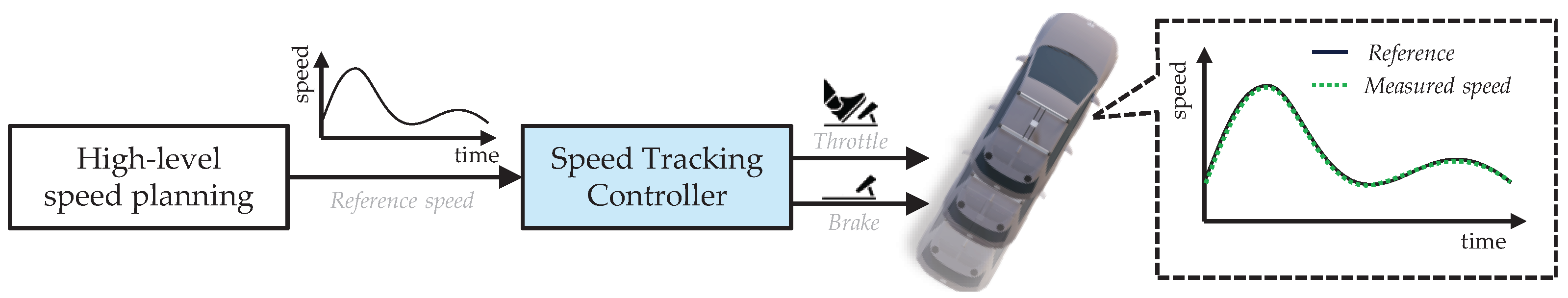
As autonomous driving technology advances, the increasing importance of accurate speed tracking in real driving scenarios such as adaptive cruise control and lane merging has led to a growing demand for improvements in longitudinal control systems. Furthermore, with the advent of Electric Vehicles (EVs) and the shift from internal combustion engines to motor-driven powertrains in recently produced vehicles, significant research and development has focused on longitudinal control methods suited to these new characteristics [1,2,3]. As shown in Figure 1, the longitudinal control systems covered in this paper output throttle or brake pedal commands to track a given speed profile created by the high-level planning system. A key requirement for these control systems is to reduce speed tracking errors without resorting to aggressive brake or throttle operations.

Figure 1.
Longitudinal speed tracking control flow. Speed tracking controller determines appropriate throttle and brake values to follow the reference speed from high-level speed planning.
Traditionally, Proportional-Integral-Derivative (PID) control has been widely utilized for longitudinal speed tracking due to its simplicity and ease of implementation without relying on a system model [4,5,6]. However, PID control does not account for system dynamics and external disturbances, which can lead to significant overshoot or persistent oscillations when subjected to noise or delays [7,8]. To address these limitations, advanced control techniques such as Sliding Mode Control (SMC) [9,10,11], Linear Quadratic Regulator (LQR) [12,13], and Model Predictive Control (MPC) [14,15,16] that directly consider vehicle dynamics have been developed. SMC, for instance, drives the system states toward a predefined sliding surface, ensuring rapid convergence to the desired state based on the designed dynamics. However, these methods are not inherently designed to minimize a given cost function or performance metric and thereby lack the ability to consider multiple objectives such as tracking performance and steering stability in the determination of control actions. In contrast, techniques like LQR and MPC solve optimization problems based on a multivariable objective function, enabling the derivation of optimal control actions that balance tracking accuracy and stability. Notably, MPC has emerged as one of the most widely studied model-based approaches in the field of autonomous driving control [17]. MPC allows for the establishment of goals considering a variety of variables, the definition of constraints on system inputs and states during the initial design phase, and the facilitation of real-time control through a receding horizon technique that continuously updates the prediction horizon [18].
Given the nature of MPC, which predicts and controls the vehicle’s state based on a model, using a model that accurately represents the longitudinal characteristics of actual vehicles can significantly improve tracking performance. Existing MPC studies [14,19,20] have focused primarily on improving vehicle dynamics models. However, to fully replicate the longitudinal behavior of real vehicles, it is crucial to consider factors such as powertrain delays in addition to dynamics. These additional factors are vital because control signals take time to be executed in the actual vehicle and actuator lag further delays the response, regardless of the vehicle model. This delay means that the calculated longitudinal commands will not be executed instantly, leading to a model mismatch and deteriorated performance. As a result, control oscillation and instability can occur.
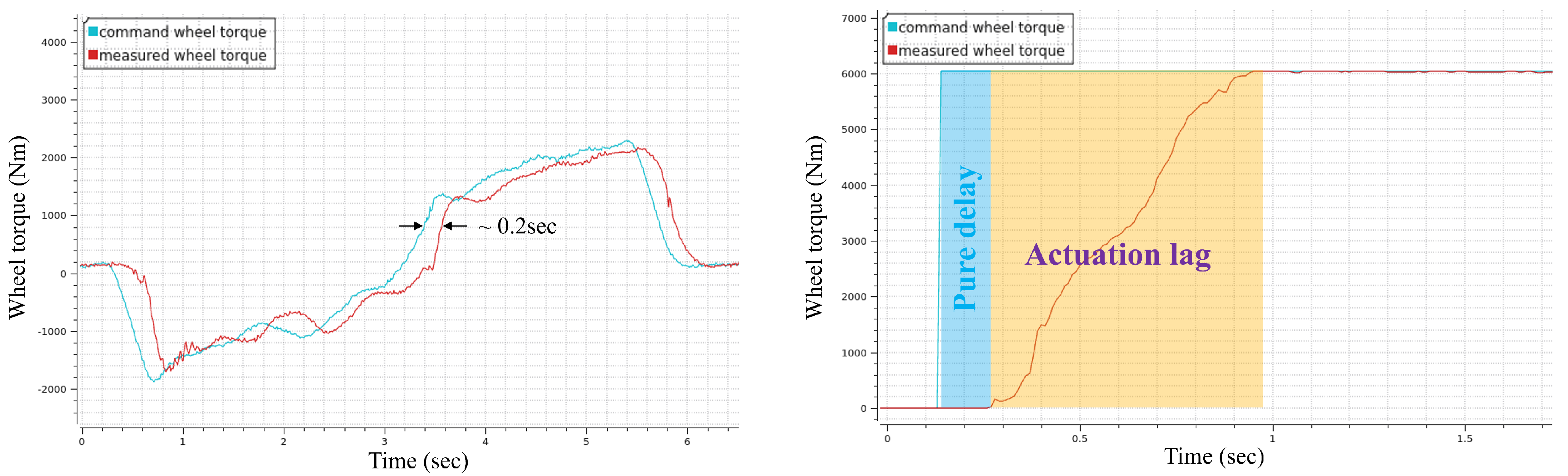
In longitudinal driving, any vehicle will experience delays in response to control inputs. As shown in Figure 2, the overall signal delay observed in our experimental electric vehicle was approximately 0.2 s. Additionally, the powertrain gradually responds after a certain period when a step wheel torque input is applied. Therefore, powertrain delays can be decomposed into pure delay and actuation lag. Pure delay arises from CAN communication and computation processes between the control module and the drive/brake motor system, and driveline freeplay, where gaps in mechanical components cause delays in torque transmission, can also contribute to pure delay. Furthermore, actuation lag occurs because the drive motor or brake actuator requires time to respond to the vehicle, and this lag is influenced by the hardware capability of the actuator and the design of the low-level control system. Moreover, mechanical filtering in the driveline, caused by the elasticity of components such as drive shafts and tires, can exacerbate this lag.
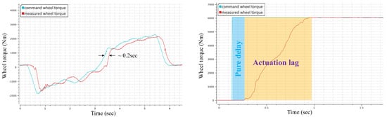
Figure 2.
Response of drive motor in the experimental EV. When comparing the measured driving wheel torque with the commanded driving wheel torque, it can be observed that there is an approximate delay of 0.2 s, which consists of a pure time delay and an actuation lag.
To address these challenges, this paper presents a novel MPC approach for longitudinal control in autonomous electric vehicles that explicitly incorporates powertrain delays into the control model using a First Order Plus Dead Time (FOPDT) model [21]. Unlike existing MPC methods that primarily focus on improving vehicle dynamics models without accounting for actuator delays, our approach models both the pure time delay and actuation lag inherent in electric vehicle powertrains. This integration allows the controller to anticipate and compensate for delays, significantly enhancing speed tracking accuracy and control stability.
Additionally, we develop detailed torque maps for both the motor and brake systems, capturing the non-linear torque characteristics of the electric vehicle’s powertrain. By integrating these torque maps into the control framework, the controller can accurately translate the desired drive force into appropriate throttle and brake inputs, further improving control precision.
The key contributions of this work are as follows:
- By incorporating a FOPDT model into the MPC, the controller effectively handles the inherent delays in electric vehicle powertrains, which has been largely overlooked in previous studies.
- The creation of detailed torque maps for the motor and brake systems, enabling precise control over throttle and brake inputs in response to the target wheel torque.
- A comprehensive evaluation of the proposed controller through both simulation and real-world experiments, demonstrating significant improvements in speed tracking accuracy and control smoothness compared to conventional MPC and PID controllers.
The remainder of this paper is organized as follows. Section 2 introduces the proposed system architecture for longitudinal speed tracking control. Section 3 delves into the MPC considering powertrain delays, while Section 4 discusses the torque map for the throttle and brake pedals. Section 5 presents the experimental results and analysis from both simulations and real vehicles. Finally, Section 6 concludes the paper.
2. Overall System Architecture
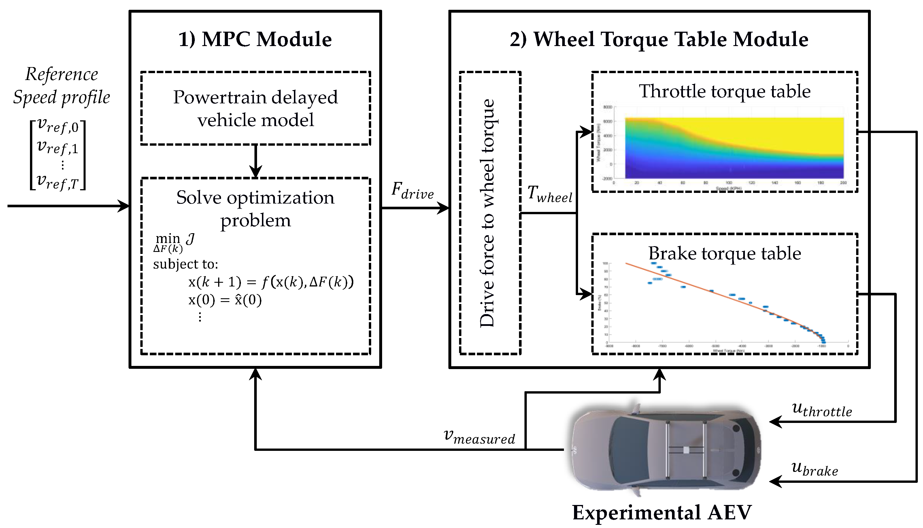
As illustrated in Figure 3, the proposed longitudinal control system for Autonomous Electric Vehicles (AEVs) tracks the reference speed profile planned by the higher-level module and outputs the throttle and brake pedal values for the vehicle. This control system is composed of two key modules: (1) a longitudinal MPC module considering powertrain delays and (2) a wheel torque table module for drive/brake torque and throttle/brake pedal values.
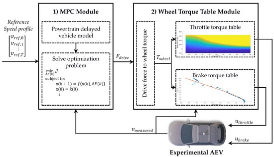
Figure 3.
Overall longitudinal control system architecture. The proposed system consists of two main modules: (1) a longitudinal MPC module that accounts for powertrain delays and (2) a wheel torque table module for converting drive force to throttle and brake pedal values.
The MPC module first receives a reference speed profile, , composed of target speeds over a fixed horizon as input, and outputs the target drive force, F. The currently measured longitudinal speed of the vehicle is used as the initial state of the MPC. The MPC solves an optimization problem using a model that considers powertrain delays, aiming to minimize the difference between the given reference speed profile and the predicted vehicle longitudinal speed.
The wheel torque table module then receives the F output from the MPC module and converts it to the wheel torque . Based on the input, the current vehicle speed, and the throttle torque table during acceleration, or the brake torque table during deceleration, it determines the throttle and brake values. These throttle and brake values are then communicated to the AEV.
This wheel torque table module is designed by acquiring driving data from the vehicle CAN, which consists of pedal positions, motor torque, acceleration, and speed, and then interpolating and smoothing the data to accurately reflect the torque characteristics of the drive motor and brakes.
3. MPC Module
3.1. Baseline Vehicle Model
The longitudinal model used in the proposed MPC system is primarily based on the vehicle’s dynamic model, incorporating factors such as aerodynamic drag, rolling resistance, and gravitational forces [22] as the following equation:
where is the vehicle’s longitudinal acceleration; m is the vehicle’s mass; F is the drive force; represents the vehicle’s pitch (substituting for the ground slope); f is the rolling resistance coefficient; and , , , v represent air density, frontal area of the vehicle, drag coefficient, and longitudinal velocity, respectively. The primary objective of this model is to accurately capture the vehicle’s longitudinal acceleration behavior under varying conditions of force and resistance. To achieve this, the model focuses exclusively on the longitudinal dynamics of the vehicle, which involves a single degree of freedom related to the longitudinal velocity. This approach ensures that the model effectively represents the vehicle’s acceleration response under the influence of longitudinal forces, without incorporating additional complexities such as lateral dynamics, suspension components, driveline, or tire models.
Based on Equation (1), a discrete-time model can be established as follows:
where the change in drive force, , is the input, u, and the speed, v, and drive force, F, are the states, x. The model update interval is represented by , and denotes the model state at time step .
3.2. Powertrain Delayed Vehicle Model
To account for the delay in the vehicle’s powertrain within the MPC model itself, a FOPDT model was integrated with the existing baseline model. This integration approximates the signal delay as dead time and the actuator lag as a first-order system. Although the time delay and lag for the drive motor and brake system can vary, and different time delays and lag parameters may be applied depending on acceleration or deceleration situations, we assume that the delay and lag elements applied to each system are identical. The FOPDT model can be expressed in the differential equation form of a continuous-time model as follows:
In the FOPDT model, represents the system’s input and represents the system’s output at time t. The dead time, D, represents pure signal delay, and the first-order system with time constant corresponds to the actuator’s lag response.
To integrate the FOPDT model into the discrete-time baseline vehicle model, a state augmentation technique was utilized. To implement the dead-time and first-order system, the state was augmented from to . The state was added to represent the first-order system, while to were added to account for the dead time. After state augmentation, the longitudinal vehicle model considering powertrain delays is as follows:
In this augmented model, the states added for dead time simply update with the drive force values from the previous steps, ensuring that the control values affect the actual baseline model after a delay of time. Furthermore, the state , added for the first-order system, ensures that the control values are gradually applied to the baseline model according to the time constant .
Finally, to transform this model into a Quadratic Programming (QP) form and solve it as a linear MPC problem, the model was linearized using a Taylor first-order expansion around the operating point based on the reference speed profile and the driving force from previous solved states. This can be expressed mathematically as follows:
Applying the powertrain delayed vehicle model to the above equation can be expressed as follows:
3.3. MPC Problem Formulation
The longitudinal MPC controller aims to minimize the error between the reference speed and the amount of change in drive force, solving a multivariable optimization problem as follows:
where Q is a diagonal weight matrix for state error and R is a weight for the change in driving force, used to find the optimal driving force that minimizes the objective function. The MPC model utilizes the linearized delayed powertrain vehicle model, with constraints on the driving force to prevent excessively large acceleration or deceleration. The resulting quadratic problem was addressed using the gradient-based, interior-point solver HPIPM [23], which uses the BLASFEO [24] linear algebra software framework. The HPIPM solver was chosen for its efficiency in handling structured QP problems typical in MPC applications, particularly due to its ability to exploit problem sparsity for faster computation, and as an open-source tool, it offers flexibility and accessibility.
4. Wheel Torque Table Module
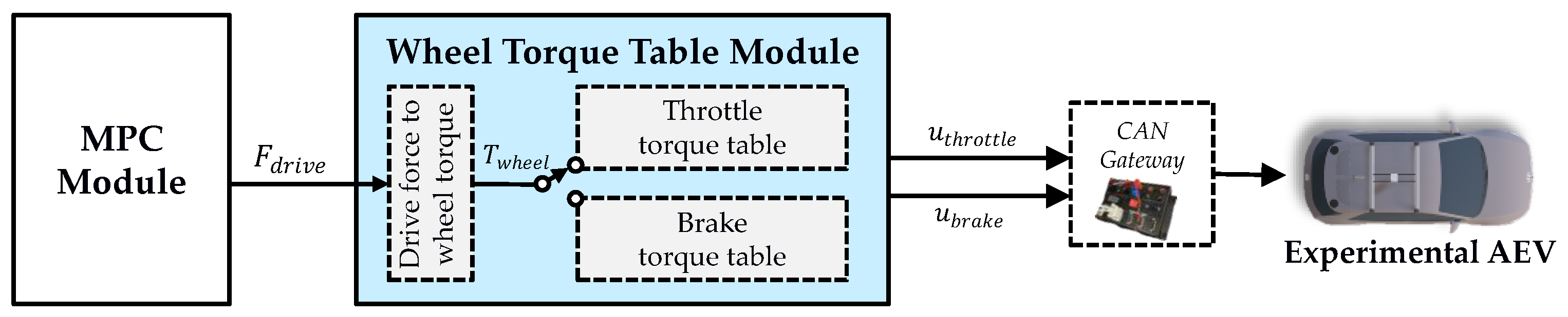
The output of the MPC module is the driving force, F, while the actual control input of the AEV is the values of the throttle and brake pedal values. Therefore, the wheel torque table module is designed to effectively convert F into throttle and brake pedal values. As illustrated in Figure 4, the F is multiplied by the wheel radius, , to convert it into the driving wheel torque, , in the initial stage of the module.
This torque is then used as the input for the wheel torque tables for throttle and brake.
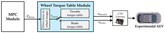
Figure 4.
Process of control commands moving from the MPC module to the AEV. The driving force, , output by the MPC module, passes through the wheel torque table module to be converted into the vehicle’s inputs and .
In the wheel torque table module, the amount of brake or throttle pedal input is determined based on the target wheel torque input, . Therefore, modeling is required for the drive motor used during acceleration and the brake system used during deceleration. To prevent simultaneous throttle and brake inputs, we use the regenerative braking torque value when both the throttle and brake pedals are at zero as a neutral value. If exceeds this neutral value, the throttle torque table is used; if it is below, the brake torque table is employed to determine the control inputs.
4.1. For the Throttle Pedal
In conventional internal combustion engine vehicles, converting torque values to throttle pedal position required torque tables for each gear, taking into account engine RPM and the current gear ratio [4,25]. However, electric vehicle powertrains mostly operate with a single gear without a transmission, eliminating the need for gear shifting and thereby requiring only one torque table for the drive motor. Given that motor torque decreases as motor RPM increases, achieving a specific torque requires different throttle positions depending on the speed of the vehicle. Therefore, in this study, motor torque data relative to vehicle speed and throttle position were collected from both on-road natural driving and experimental driving on the proving ground.
As shown in the data acquired section of Figure 5, the orange data obtained from the proving ground tests with constant throttle inputs and the blue data distribution obtained from normal on-road driving are presented. The necessary vehicle speed, throttle position, and motor torque data for the table generation were collected through the vehicle CAN. Then, as illustrated in the wheel torque table of Figure 5, these data were interpolated into continuous values using the cubic spline approximation method [26] to create a lookup table. Through this process, when the current speed and target wheel torque values are input, the appropriate amount of throttle pedal is determined.
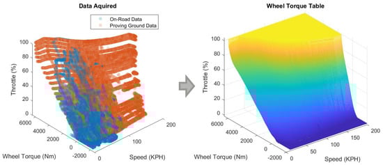
Figure 5.
Acquired drive wheel torque data from on-road driving and proving ground tests, and generated drive motor torque table for the throttle. The drive wheel torque data were obtained by converting the drive motor torque from the vehicle CAN, and these data were interpolated and smoothed to create a lookup table.
4.2. For the Brake Pedal
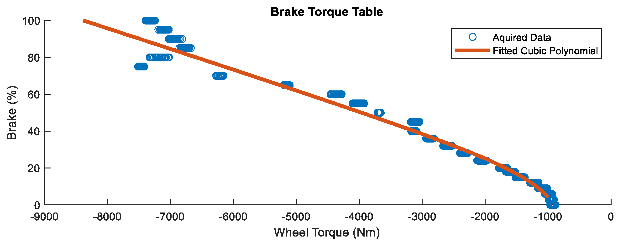
The vehicle’s brake system is designed based on hydraulic brakes, which typically provide braking force proportional to the brake pedal input. Therefore, when determining the required brake pedal input for a target drive wheel torque, speed information is not necessary, unlike in the case of the throttle pedal, and the modeling can be conducted based on the relationship between the brake pedal input and the drive wheel torque. However, unlike the motor torque used for the throttle pedal, the torque values during braking are not provided by the vehicle’s CAN bus. Thus, to convert the longitudinal acceleration data obtained from the CAN into wheel torque, we inversely applied Equations (1) and (8) inversely to convert the longitudinal acceleration value obtained from the CAN into wheel torque. Subsequently, as illustrated in Figure 6, this relationship was modeled using a cubic polynomial, such that when a target wheel torque below the neutral value is input, the appropriate brake pedal input is determined.
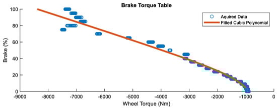
Figure 6.
Generated brake torque table. Data were collected by increasing the brake input by 10% increments from an initial speed of 100 km/h. From 70% brake input onwards, similar brake torque was observed due to the intervention of the Anti-lock Braking System (ABS).
5. Experiment
The speed tracking performance of the proposed MPC, which considers powertrain delay, is analyzed against a conventional MPC that does not consider delay and a classical PID control approach. The main parameters of the proposed MPC are shown in Table 1. A wheel torque table module is used uniformly across all controllers to ensure consistency in the evaluation. All these control algorithms were implemented in C++ on the Ubuntu ROS1 Noetic middleware and were run on an Intel i9-13900TE CPU (Intel, Santa Clara, CA, USA) with 64 GB of RAM.

Table 1.
Main parameters of proposed MPC.
5.1. Comparative Controllers
(1) Conventional MPC: This MPC without a delay consideration approach utilizes the proposed MPC framework but omits the FOPDT model, simplifying the system model to include only vehicle speed and drive force as a state X without considering dead time and lag, i.e., . The inputs remain the same, , as in the powertrain delay considered MPC. The discrete linearized model for this controller is defined as follows:
and all parameters are the same as in the delay considered MPC.
(2) PID: The PID controller is a widely used control technique across various industries due to its simplicity and effectiveness in a range of applications. The method operates on the principle of feedback control, where the control action is based on the difference between the current speed and the reference speed from the speed profile. The speed profile, part of the vehicle’s reference trajectory, provides target speeds assigned to the closest trajectory points relative to the vehicle. Through careful tuning of the P, I, and D gains, the PID controller calculates the appropriate target wheel torque, , to accurately follow the target speed.
5.2. Simulation Validation
To evaluate the performance of the proposed MPC considering powertrain delay, we first compared the proposed MPC with powertrain delay, a conventional MPC, and a PID controller in the IPG Automotive CarMaker vehicle simulator. The simulation used a Hyundai IONIQ5 electric vehicle provided by CarMaker, and a wheel torque map module was specifically designed for the simulated vehicle using data acquired from the simulator. The vehicle parameters used in this paper were based on the IONIQ5 data from CarMaker, as shown in Table 2. The powertrain delay in the simulator was modeled as 0.1 s using a queue buffer, while the lag was modeled as 0.15 s using a first-order system, both applied just before the throttle and brake inputs. The performance of the proposed MPC with delay consideration was compared against an MPC without delay consideration and a PID controller, and validation was performed under two scenarios: (1) a step speed profile from 30 km/h to 50 km/h and (2) a trapezoidal speed profile with acceleration and deceleration ranging from −4 m/s2 to 4 m/s2.
Table 2.
Vehicle parameters for validation and experimental AEV.
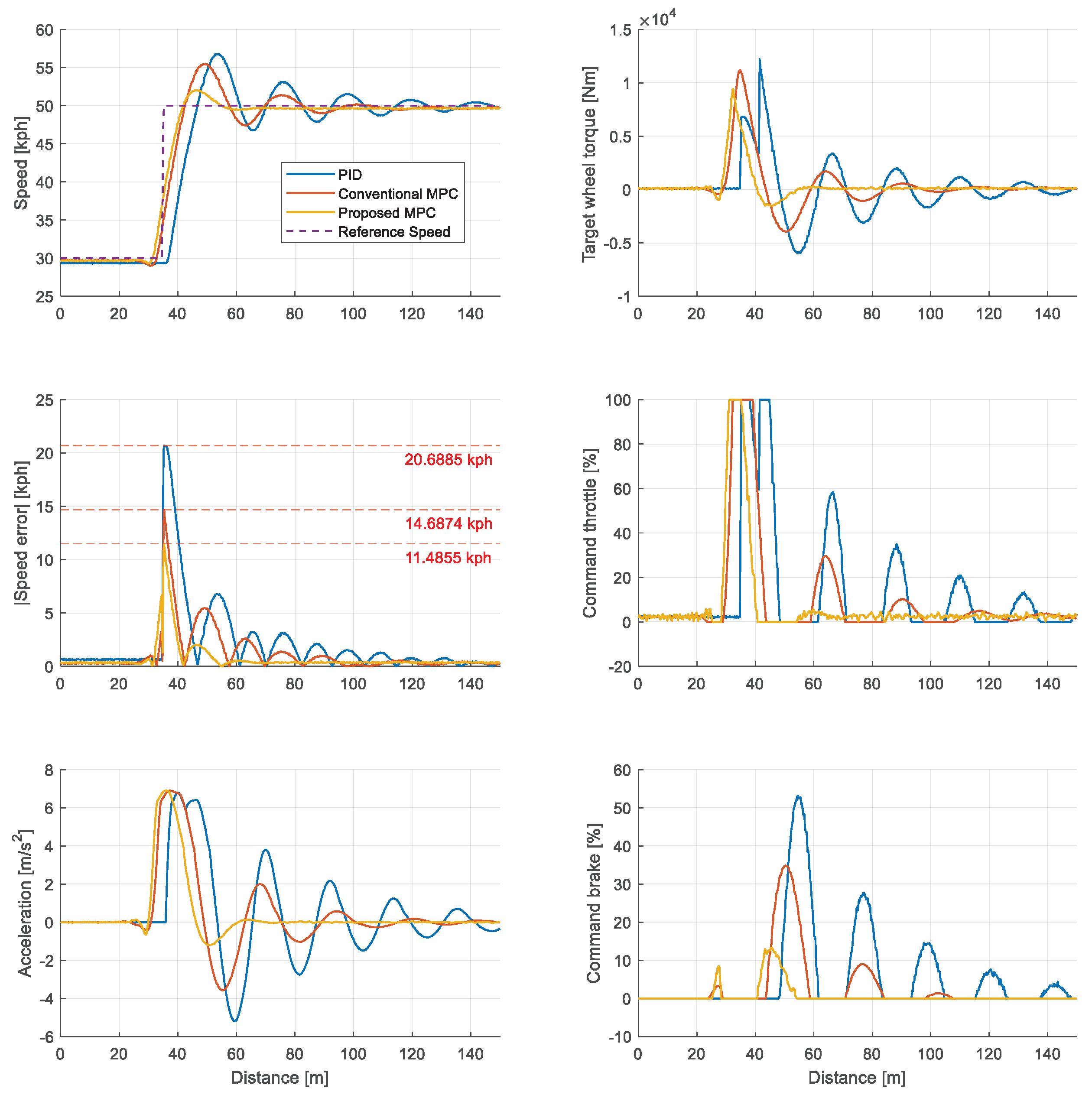
First, the driving results for the step speed profile are shown in Figure 7. In the subfigure for target wheel torque and commanded throttle, the MPC-based methods began accelerating earlier than the PID controller, owing to their ability to predict future states through the prediction horizon. As a result, the PID controller showed the slowest response to the step speed profile and, therefore, exhibited the lowest speed tracking accuracy. The conventional MPC, which did not account for powertrain delay, demonstrated slower convergence compared to the proposed MPC and responded later to the step speed profile. As shown in Table 3, the proposed MPC exhibited the highest speed tracking accuracy among the three controllers, with a maximum speed error of 11.48 km/h and an average speed error of 0.68 km/h.
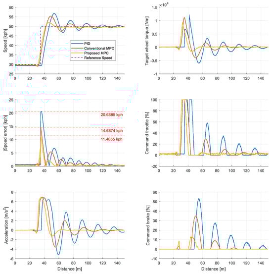
Figure 7.
Simulation result of step speed profile in CarMaker simulator. This scenario involves tracking a reference speed that increases from 30 km/h to 50 km/h.
Table 3.
Speed tracking performance of step speed profile in the simulation.
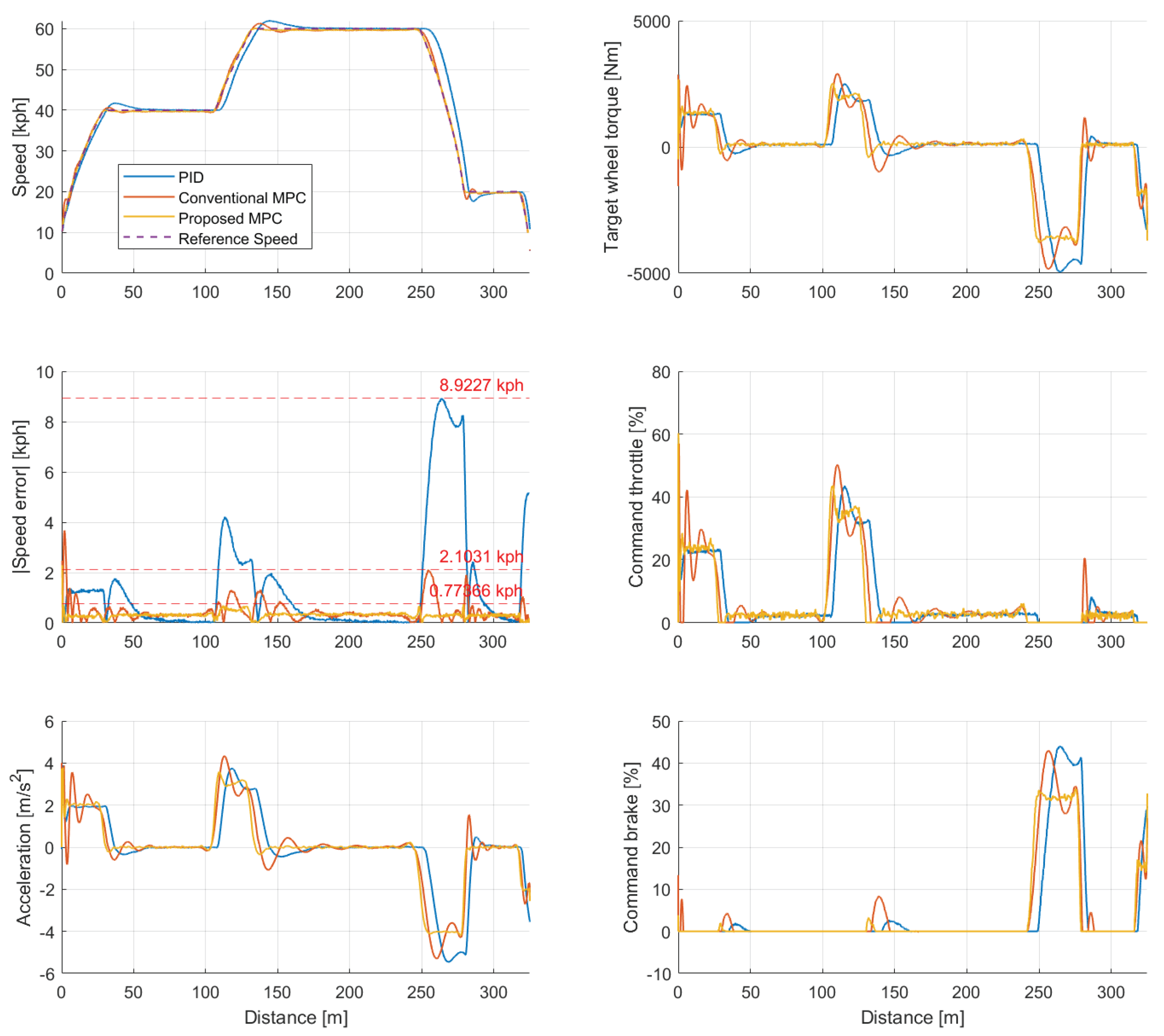
Second, when examining the tracking performance for the trapezoidal speed profile shown in Figure 8, similar to the step speed profile scenario, it can be observed that the proposed MPC, conventional MPC, and PID controller responded quickly to the acceleration and deceleration speed profiles in that order. Also, the proposed MPC had the smallest control overshoot and thus required the smallest amount of control input. Through this, the proposed MPC’s longitudinal acceleration converged to a stable value without oscillation during both acceleration and deceleration phases. As shown in Table 4, the maximum absolute speed error was largest for the PID controller (8.93 km/h), followed by the conventional MPC (2.19 km/h), and smallest for the proposed MPC (0.77 km/h). This result indicates that the proposed longitudinal controller quickly responds to the given speed profile in the presence of powertrain delays and exhibits excellent speed tracking performance.
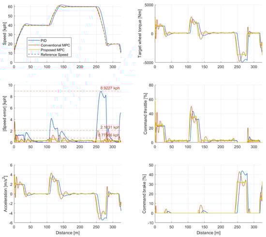
Figure 8.
Simulation result of the trapezoidal speed profile in the CarMaker simulator. This scenario involves tracking a reference speed with acceleration and deceleration ranging from −4 m/s2 to 4 m/s2.
Table 4.
Speed tracking performance of trapezoidal speed profile in the simulation.
5.3. Real-World Vehicle Experiment
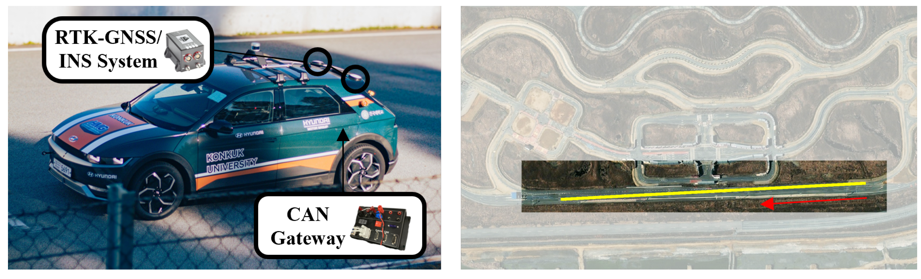
For the real vehicle experiments, the same speed profile used in the simulator verification was used, with additional acceleration and deceleration phases added towards the end. As shown in Figure 9, these tests were conducted at a highway section of the K-City, the autonomous driving testbed of the Korea Automotive Technology Institute. The experimental vehicle was a Hyundai IONIQ5 AWD model, and the wheel torque map module was also developed based on real vehicle experimental data. Vehicle pose estimation utilized results from a Novatel CPT7 dual antenna RTK-GNSS/INS solution, and vehicle control inputs, including throttle and brake pedal positions, were applied through a CAN/CAN-FD gateway.

Figure 9.
Experimental AEV Platform, Hyundai IONIQ5, and the test site, K-City highway section.
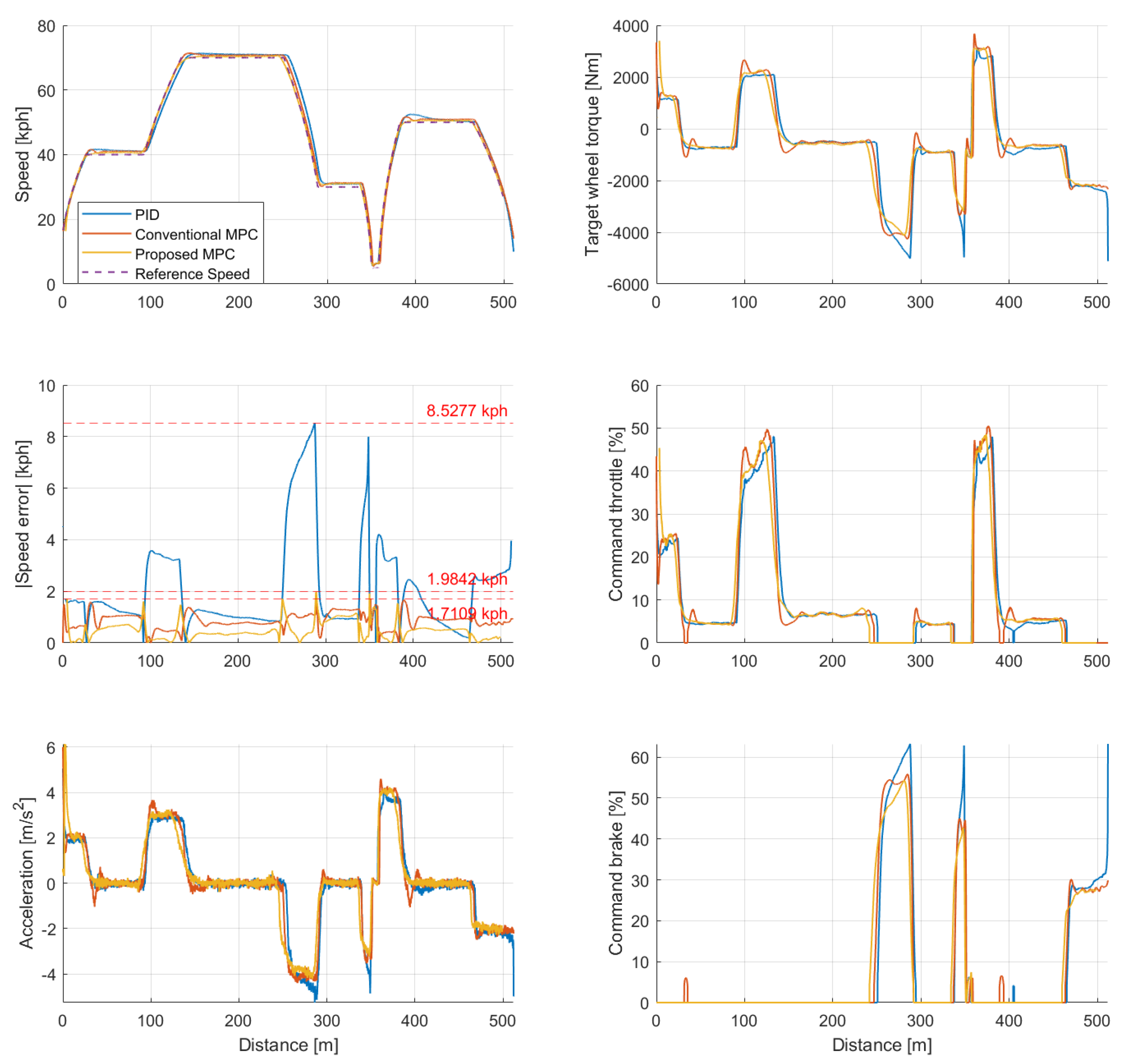
In the real-vehicle experiments, the same three controllers used in the simulation validation were tested for speed tracking performance, and the experimental results are presented in Figure 10. In the speed error subplot, the PID controller shows high errors during rapid acceleration and deceleration due to its delayed response in following the reference speed. Additionally, while the conventional MPC reduced the speed error with a faster response than the PID controller, thanks to its predictive characteristics, the target wheel torque subplot shows that it converged more slowly than the proposed MPC. As shown in Table 5, the maximum absolute speed error was highest for the PID controller (8.53 km/h), followed by the proposed MPC (1.98 km/h), and the conventional MPC (1.71 km/h). The ranking for mean absolute speed error differed slightly, with the PID controller showing the highest error (2.12 km/h), followed by the conventional MPC (0.88 km/h), and the proposed MPC exhibiting the lowest error (0.54 km/h).

Figure 10.
Real-vehicle experiment result of the trapezoidal speed profile in K−City. This scenario involves tracking a reference speed with acceleration and deceleration ranging from −4 m/s2 to 4 m/s2.
Table 5.
Speed tracking performance in the real-vehicle experiment.
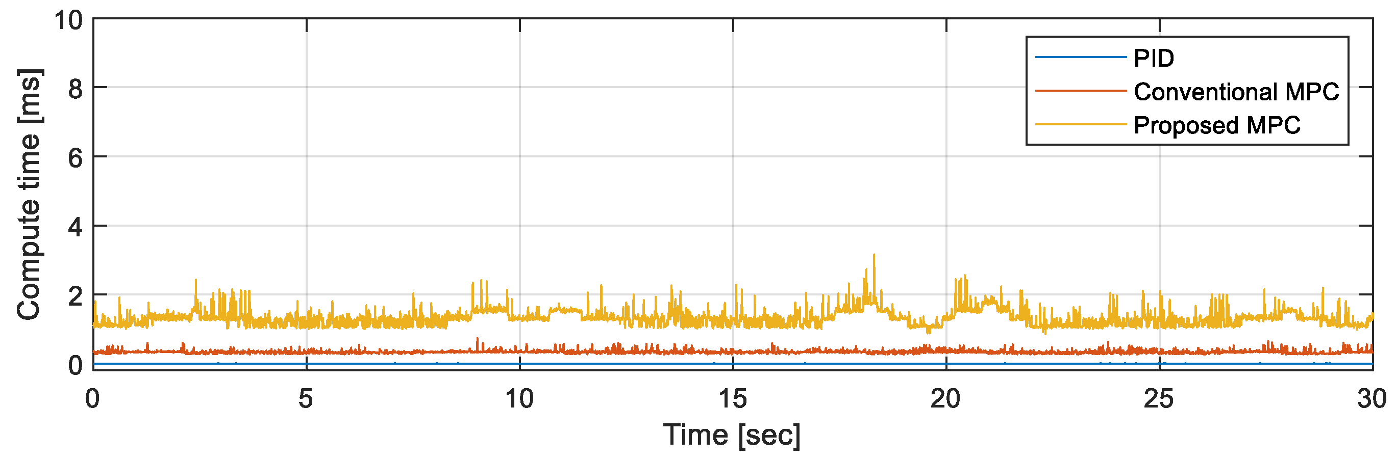
Compared to the simulation, tracking errors increased due to external disturbances and approximations in the actual model. However, the proposed MPC still showed the best performance in terms of mean error. The PID controller exhibited significant overshoots in acceleration and deceleration due to its delayed response. While the conventional MPC demonstrated speed tracking performance similar to the proposed MPC, it showed larger overshoots in the target wheel torque during the acceleration and deceleration phases compared to the proposed algorithm. As confirmed in Figure 11 and Table 6, although the computation time increased due to the additional number of states, the proposed MPC sufficiently maintained real-time performance, with an average computation time of 1.32 ms, satisfying the CAN data cycle requirement of 10 ms.
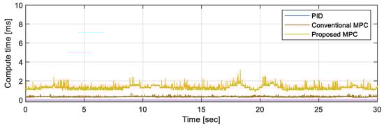
Figure 11.
Computational time of each comparative controller.
Table 6.
Mean computational time of each comparative controller.
6. Conclusions
This paper proposes a longitudinal control system that considers powertrain delay to enhance speed tracking performance in autonomous electric vehicles. The longitudinal controller models the actuator lag and signal delays as a FOPDT model, incorporating them into the MPC module. The resulting wheel torque output is converted into the throttle and brake pedal positions using a torque table. The designed controllers were implemented and tested on a Hyundai IONIQ5, demonstrating reduced speed tracking errors and smoother control behaviors. Despite an increase in the number of states, real-time performance is still maintained with a response time of less than 10 ms. The proposed controller has been validated through both simulator and real-vehicle experiments, offering superior speed tracking performance and eliminating acceleration and deceleration overshoots compared to traditional PID and MPC methods, which do not consider powertrain delays. Future work will focus on online estimation of powertrain delays, which is expected to reduce the time and effort required for system calibration and further improve the control system’s adaptability and performance.
Author Contributions
Conceptualization, J.L.; methodology, J.L.; software, J.L.; validation, J.L.; formal analysis, J.L.; investigation, J.L.; resources, J.L.; data curation, J.L.; writing—original draft preparation, J.L.; writing—review and editing, J.L.; visualization, J.L.; supervision, K.J.; project administration, K.J.; funding acquisition, K.J. All authors have read and agreed to the published version of the manuscript.
Funding
This research was supported by a Korea Institute for Advancement of Technology (KIAT) grant funded by the Korean Government (MOTIE) (P0020536, HRD Program for Industrial Innovation) and a National Research Foundation of Korea (NRF) grant funded by the Korean government (MSIT) (No. RS-2023-00209252).
Data Availability Statement
The original contributions presented in the study are included in the article; further inquiries can be directed to the corresponding author.
Acknowledgments
This research was originally presented as an oral poster at the EVS37 conference held in Seoul, Republic of Korea, on 25 April 2024. We extend our heartfelt gratitude to the EVS37 program committee for the esteemed opportunity to contribute this paper to the Special Issue of the World Electric Vehicle Journal.
Conflicts of Interest
The authors declare no conflicts of interest.
References
- Geamanu, M.S.; Mounier, H.; Niculescu, S.I.; Cela, A.; LeSolliec, G. Longitudinal control for an all-electric vehicle. In Proceedings of the 2012 IEEE International Electric Vehicle Conference, Greenville, SC, USA, 4–8 March 2012; pp. 1–6. [Google Scholar]
- He, H.; Han, M.; Liu, W.; Cao, J.; Shi, M.; Zhou, N. MPC-based longitudinal control strategy considering energy consumption for a dual-motor electric vehicle. Energy 2022, 253, 124004. [Google Scholar] [CrossRef]
- El Majdoub, K.; Giri, F.; Ouadi, H.; Chaoui, F. Nonlinear cascade strategy for longitudinal control of electric vehicle. J. Dyn. Syst. Meas. Control. 2014, 136, 011005. [Google Scholar] [CrossRef] [PubMed]
- Hamersma, H.A.; Els, P.S. Longitudinal vehicle dynamics control for improved vehicle safety. J. Terramechanics 2014, 54, 19–36. [Google Scholar] [CrossRef]
- Nie, L.; Guan, J.; Lu, C.; Zheng, H.; Yin, Z. Longitudinal speed control of autonomous vehicle based on a self-adaptive PID of radial basis function neural network. IET Intell. Transp. Syst. 2018, 12, 485–494. [Google Scholar] [CrossRef]
- Lu, C.; Gong, J.; Lv, C.; Chen, X.; Cao, D.; Chen, Y. A personalized behavior learning system for human-like longitudinal speed control of autonomous vehicles. Sensors 2019, 19, 3672. [Google Scholar] [CrossRef] [PubMed]
- Xu, S.; Peng, H.; Song, Z.; Chen, K.; Tang, Y. Accurate and smooth speed control for an autonomous vehicle. In Proceedings of the 2018 IEEE Intelligent Vehicles Symposium (IV), Changshu, China, 26–30 June 2018; pp. 1976–1982. [Google Scholar]
- MacAdam, C.C. Application of an optimal preview control for simulation of closed-loop automobile driving. IEEE Trans. Syst. Man Cybern. 1981, 11, 393–399. [Google Scholar] [CrossRef]
- Nouveliere, L. Experimental vehicle longitudinal control using a second order sliding mode technique. Control. Eng. Pract. 2007, 15, 943–954. [Google Scholar] [CrossRef]
- Ferrara, A.; Incremona, G.P. Sliding modes control in vehicle longitudinal dynamics control. In Advances in Variable Structure Systems and Sliding Mode Control—Theory and Applications; Springer: Berlin/Heidelberg, 2018; pp. 357–383. [Google Scholar]
- Jo, A.; Lee, H.; Seo, D.; Yi, K. Model-reference adaptive sliding mode control of longitudinal speed tracking for autonomous vehicles. Proc. Inst. Mech. Eng. Part D J. Automob. Eng. 2023, 237, 493–515. [Google Scholar] [CrossRef]
- Perng, J.W.; Lai, Y.H. Robust longitudinal speed control of hybrid electric vehicles with a two-degree-of-freedom fuzzy logic controller. Energies 2016, 9, 290. [Google Scholar] [CrossRef]
- Jung, H.; Jung, D.; Choi, S.B. LQR control of an all-wheel drive vehicle considering variable input constraint. IEEE Trans. Control. Syst. Technol. 2021, 30, 85–96. [Google Scholar] [CrossRef]
- Matute, J.A.; Marcano, M.; Zubizarreta, A.; Perez, J. Longitudinal model predictive control with comfortable speed planner. In Proceedings of the 2018 IEEE International Conference on Autonomous Robot Systems and Competitions (ICARSC), Torres Vedras, Portugal, 25–27 April 2018; pp. 60–64. [Google Scholar]
- Sun, X.; Cai, Y.; Wang, S.; Xu, X.; Chen, L. Optimal control of intelligent vehicle longitudinal dynamics via hybrid model predictive control. Robot. Auton. Syst. 2019, 112, 190–200. [Google Scholar] [CrossRef]
- Qiu, W.; Ting, Q.; Shuyou, Y.; Hongyan, G.; Hong, C. Autonomous vehicle longitudinal following control based on model predictive control. In Proceedings of the 2015 34th Chinese Control Conference (CCC), Hangzhou, China, 28–30 July 2015; pp. 8126–8131. [Google Scholar]
- Yu-Geng, X.; De-Wei, L.; Shu, L. Model predictive control—Status and challenges. Acta Autom. Sin. 2013, 39, 222–236. [Google Scholar]
- Huang, Y.; Wang, H.; Khajepour, A.; He, H.; Ji, J. Model predictive control power management strategies for HEVs: A review. J. Power Sources 2017, 341, 91–106. [Google Scholar] [CrossRef]
- He, Z.; Gong, L.; Zhou, E.; Wei, B.; Li, E.; Huang, J. Lateral and Longitudinal Coordinated Control of Intelligent Vehicle Based on High-Precision Dynamics Model under High-Speed Limit Condition. IEEE Trans. Intell. Veh. 2024. [Google Scholar] [CrossRef]
- Chen, S.p.; Xiong, G.m.; Chen, H.y.; Negrut, D. MPC-based path tracking with PID speed control for high-speed autonomous vehicles considering time-optimal travel. J. Cent. South Univ. 2020, 27, 3702–3720. [Google Scholar] [CrossRef]
- Bagheri, P.; Sedigh, A.K. Analytical approach to tuning of model predictive control for first-order plus dead time models. IET Control. Theory Appl. 2013, 7, 1806–1817. [Google Scholar] [CrossRef]
- Rajamani, R. Vehicle Dynamics and Control; Springer Science & Business Media: Berlin/Heidelberg, Germany, 2011. [Google Scholar]
- Frison, G.; Diehl, M. HPIPM: A high-performance quadratic programming framework for model predictive control. IFAC-PapersOnLine 2020, 53, 6563–6569. [Google Scholar] [CrossRef]
- Frison, G.; Kouzoupis, D.; Sartor, T.; Zanelli, A.; Diehl, M. BLASFEO: Basic linear algebra subroutines for embedded optimization. ACM Trans. Math. Softw. TOMS 2018, 44, 1–30. [Google Scholar] [CrossRef]
- Dekraker, P.; Barba, D.; Moskalik, A.; Butters, K. Constructing Engine Maps for Full Vehicle Simulation Modeling; Technical Report, SAE Technical Paper; SAE International: Warrendale, PA, USA, 2018. [Google Scholar]
- De Boor, C.; De Boor, C. A Practical Guide to Splines; Springer: New York, NY, USA, 1978; Volume 27. [Google Scholar]

Disclaimer/Publisher’s Note: The statements, opinions and data contained in all publications are solely those of the individual author(s) and contributor(s) and not of MDPI and/or the editor(s). MDPI and/or the editor(s) disclaim responsibility for any injury to people or property resulting from any ideas, methods, instructions or products referred to in the content. |
© 2024 by the authors. Published by MDPI on behalf of the World Electric Vehicle Association. Licensee MDPI, Basel, Switzerland. This article is an open access article distributed under the terms and conditions of the Creative Commons Attribution (CC BY) license (https://creativecommons.org/licenses/by/4.0/).