Article

A Study on the Performance of the Electrification of Hydraulic Implements in a Compact Non-Road Mobile Machine: A Case Applied to a Backhoe Loader

by
Mariana de F. Ramos
1,*,
Dener A. de L. Brandao
1,
Diogo P. V. Galo
1,2,
Braz de J. Cardoso Filho
3,
Igor A. Pires
4 and
Thales A. C. Maia
3
1
Graduate Program in Electrical Engineering, Universidade Federal de Minas Gerais, Belo Horizonte 31270-901, Brazil
2
CNH Industrial Brazil, Contagem 32210-900, Brazil
3
Department of Electrical Engineering, Universidade Federal de Minas Gerais, Belo Horizonte 31270-901, Brazil
4
Department of Electronic Engineering, Universidade Federal de Minas Gerais, Belo Horizonte 31270-901, Brazil
*
Author to whom correspondence should be addressed.
World Electr. Veh. J. 2024, 15(4), 127; https://doi.org/10.3390/wevj15040127
Submission received: 15 January 2024 / Revised: 11 March 2024 / Accepted: 13 March 2024 / Published: 22 March 2024

Abstract

:
This work presents a study of the performance of prime mover and hydraulic implement electrification in a backhoe loader. The results are validated through simulation and experimental tests. The construction and agriculture sector has grown in recent years with the aid of compact non-road mobile machines. However, as is common in fossil fuel-powered vehicles, they significantly contribute to increasing emissions. Previous research has primarily relied on powertrain electrification to address the low-efficiency drawbacks. Notably, compact off-road vehicles comprise implements less discussed in the literature. A hybrid series topology is employed, where the rear implement is driven by an electrical drive and the Diesel engine is coupled to a generator. A rule-based energy management strategy is applied. The operation of the Diesel engine and electrical machines in optimal points of the efficiency maps are the basis of the analysis. The design is validated using simulations and experimental tests in a commercial backhoe loader as a benchmark. Experimental and simulation results obtained from the hybrid series backhoe loader applied to the hydraulic implement show a 33% reduction in fuel consumption, demonstrating the effectiveness of electrification in reducing emissions and fuel consumption of compact non-road mobile machines.

1. Introduction

Worldwide transportation has grown significantly over the last few years. For instance, in the United States only, from 2001 to 2019, the total number of registered private and commercial vehicles increased by 20%, from 226.6 million to 272.4 million [1]. Internal combustion engines (ICEs) propel these vehicles, typically fueled by fossil fuels. Pollutant emissions from these engines contribute significantly to increased air pollution by emitting carbon monoxides (CO), hydrocarbons (HC), nitrogen oxides (NOx), and particulate matter (PM) to the atmosphere [2].
Non-road mobile machines (NRMM) also contribute to these emissions. A study conducted in Poland compared the fuel consumption of farming machinery between 2012 and 2013. The findings indicated that emissions from agricultural non-road machines had a higher impact on the total emissions of CO (39.837 tonnes), NOx (42.281 tonnes), hydrocarbons (8072 tonnes), and PM (3947 tonnes) [3]. An alternative for reducing these emissions is through the electrification of the powertrain of these machines.
Compact non-road machines experience distinct torque and speed demands in contrast to the profile presented by road vehicles, with constant speed and few torque variations. Due to their operations on high torque and low speed, conventional combustion engines operate at low efficient points. Electrical drives offer higher torque density at lower speeds. Additionally, they exhibit improved efficiency across a wider range of operating speeds and require less maintenance due to fewer mechanical components [4].
Common electrification technologies used in compact non-road machines’ design include fully electric or hybrid systems. Brenna et al. discuss crucial design aspects for electrifying heavy-duty farm tractors, emphasizing the complete replacement of the Diesel engine with an electric motor to achieve optimal operation [5]. However, drawbacks are associated with this architecture, such as the size of the battery pack and the need to halt operations for recharging [6]. Therefore, combining a hybrid series architecture with a downsized internal combustion engine led to a 33.4% reduction in fuel consumption when applied to a snowblower [7]. Similarly, the application of a hybrid parallel topology to an agricultural tractor resulted in a decrease of 24.77% in fuel consumption during the heavy cultivation cycles [8]. Both works relied on simulations and experimental tests to validate the proposed vehicle design changes.
The literature on compact non-road machines predominantly focuses on the electrification of the powertrain [9,10,11,12,13,14,15,16,17,18,19], with limited exploration beyond traction systems. However, there are models of off-road machines in which the hydraulic system is activated more frequently during the operation profile, like excavators and wheel loaders [20]. Mendes et al. present a project for sizing and analyzing the hybridization of the implements of a backhoe loader but fall short by not providing the development of the proposed simulation model and by not conducting experimental tests to validate the approach [21]. In contrast, Do et al. present a model for the full electrification of the implement of a hydraulic excavator [22] but do not carry out experimental validation. Also, the study lacks a fuel consumption analysis.
A comprehensive analysis of pertinent state-of-the-art works is presented in Table 1. The works were classified into machinery types and electrification technologies. Furthermore, the table also illustrates the research gaps covered in this work, such as the modeling of efficiency maps of combustion engines and electrical machines, whether they address fuel consumption, and whether there is experimental validation of the results. It also shows that major works focus on powertrain electrification. Among them, only one study carries out an experimental validation of the results. To the best of the authors’ knowledge, there are no works in the literature on the hybridization of compact non-road mobile machines focusing on implements and carrying out an experimental validation of the results. This work aims to present a study on this topic.
The main contribution of this paper is to present a study on the hybridization performance of the rear implement of a commercial backhoe through simulation and validation through experimental results. The improvements are evaluated through the machine’s fuel consumption during operation. The hybrid prototype adopted a series topology, where the internal combustion engine was disconnected from the hydraulic pump and linked to a generator. Meanwhile, an electric motor powered the hydraulic implements. Real trenching cycle experiments were conducted to gather data on ICE performance, fuel usage, and energy consumption. This information was then used in simulations based on quasi-static efficiency maps to validate the results.

2. Electrification of Non-Road Mobile Machinery

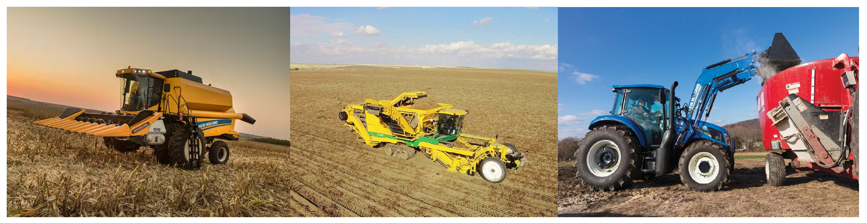
2.1. Classification by Usage

In this work, the definition of non-road mobile machinery is also presented as mobile working machines on wheels or tracks suitable for operating in off-road environments. Adopting this concept makes sense when considering that the definition of vehicles per se is associated with transporting passengers and goods on land in machinery with an engine and wheels [24].
Hagan et al.’s classification categorizes non-road mobile machines based on their usage characteristics, as detailed in Table 2 [3,25]. For instance, various vehicles exhibit distinct purposes and configurations within the agricultural sector alone, illustrated in Figure 1.
Construction machines comprise the largest group among non-road mobile machines, and agricultural machines constitute the second largest group [26]. Therefore, this study will be focusing on construction machines.

2.2. Classification by Power Demand

Non-road mobile machines exhibit variability based on their intended application. The design of their major components, such as the powertrain, hydraulic system, and electrification architecture, is tailored to suit specific applications and the demanded power. In instances where off-highway vehicles serve specialized purposes, the power requirements differ among types. The dynamics of the operational cycle and the materials manipulated by the machine play a significant role in determining these characteristics.
A single type of non-road machinery can exhibit a wide range of power ratings. Therefore, for design purposes, the classification by function becomes less relevant. Table 3 presents the classification defined in this work for off-road mobile machines according to the rated power. According to Dallman and Menon, the most common power class for construction equipment has a range of rated power from 56 to 75 kW [27]. Given that compact machines fall within this power rating classification, they will be the primary focus of this study.
Table 4 showcases examples of commercially available machines categorized by their nominal power range [28]. Upon analysis, it becomes evident that the backhoe loaders are the construction compact non-road vehicles with the smallest range of power ratings, making them easier to analyze and the case study of this work.

2.3. Electrification Strategies: Current Achievements and Challenges

The initial stages of the design involve the definition of the constraints that guide the cost–benefit considerations. The starting point begins with the determination of vehicle specifications, drive cycle requirements, and analyzing the machine’s power profile. Subsequently, attention shifts to the definition of the optimal architecture to implement these specifications effectively. The main architectures presented in the literature are battery electric and hybrid electric, with topologies including series, parallel, and series–parallel.
Full electrification would be the most advisable option in this case because it proves itself capable of achieving the ideal operation concerning emissions and fuel usage during machinery operation. As an example, Caterpillar designed the world’s first small-scale electric excavator, CAT-323F Z-line [29], with a battery capacity of 300 kWh and autonomy of five to seven hours. Another model is the CASE 580EV backhoe loader, which is coupled with a pack of batteries powering the transmission and hydraulic motors [30].
The necessity to ensure at least an equivalent autonomy to combustion engine-powered equipment becomes a challenge because of the size of the pack of batteries to ensure it. Packing this system into a vehicle in the available space without considerable modifications to the chassis is complicated. In this way, the hybrid path becomes attractive.
A machine is defined as hybrid if, to perform its functions, it has at least two distinct sources of energy, one of which is potentially reversible [31]. From this definition, numerous solutions exist when opting for a hybrid architecture. In the work of Brandão et al. [32], the main advantages and disadvantages of series, parallel, and series–parallel topologies are analyzed. When the maintenance of the internal combustion engine is a project premise, the focus should be on reducing fuel consumption. With this in mind, series and series–parallel topologies are the ones that allow for a greater degree of freedom to place the engine at an optimal operating point.
Multiple energy conversions carried out in the series topology reduce the system’s overall efficiency. However, the series–parallel topology has more components (e.g., planetary gear) that increase the costs of the solution. Since there will be no changes to the vehicle’s chassis, mechanical parts, or downsizing of the internal combustion engine, the series topology is the most suitable for this application.
Figure 2 presents the hybrid series topology [32]. It allows the internal combustion engine to be placed in an optimal efficiency region (unlike parallel topology). It has fewer components than the series–parallel topology, facilitating the integration of new parts into the existing chassis.
Considering the ongoing efforts to enhance the machine’s overall efficiency, another crucial factor pertains to the comparatively low efficiency of hydraulic drives. When contrasted with electric drives, electric machines generally exhibit lower losses than those encountered in hydraulic systems [31]. For instance, the hydraulic drive responsible for the rotation of an excavator can experience losses of 50%, contingent on component types and operational conditions. In contrast, an electric drive can achieve comparable performance with a minimum efficiency of 60% [33]. However, this topology introduces complexity and project costs due to the additional components, posing a challenge within limited space constraints.

2.4. Simulation Strategies: Current Methodologies

Experimental tests are a logical path to follow in achieving the proposal of analyzing the electrification project of a compact non-road machine, concerning operational efficiency, emissions, and fuel consumption. Vu et al. compare the operation of the traditional vehicle and the prototype of the electrified machine [7]. Even though this is the best approach to analyze important modifications and their impacts on vehicle performance, the possibility of prototyping and testing it does not always present itself.
The work developed by Mendes et al. [21] is one of the first to focus on backhoe loaders. It presents a vehicle hybridization methodology applied to a backhoe loader. The main focus is on the design and sizing of the components of the hybrid vehicle—hydraulic power, energy storage system, and control methodologies. However, there is little emphasis on how to simulate and achieve the desired results.
Taherzadeh et al., for instance, present the advance vehicle simulator (Advisor) as the simulation tool to validate the proposed control strategy [34]. Advisor is a widely used tool in the design and analysis of road vehicles. Adapting this tool can be complicated, considering that non-road vehicles have greater specificities, especially concerning their work cycle. Furthermore, Do et al. simulate power management strategies for a proton-exchange membrane fuel cell electric excavator with a supercapacitor/battery hybrid power source with AMESim 15.2 and MATLAB R2021b [22]. A negative point of this work is that it is a purely electric excavator simulation, so the modeling of the combustion system is not covered.
When seeking to analyze the system’s performance as a whole, there is no need to simulate in detail all the components, couplings, and energy flows necessary for the machine’s functionality. Mainly, a graphical depiction of subsystem interactions regarding energy flowing in the hybrid non-road mobile machine is sufficient [7]. This approach focuses on lookup tables, and it combines reliability, when considering known characteristics, to a necessary computational simplicity, while evaluating the behavior of the vehicle operation. Troncon et al. present a backward-facing model, also known as the quasi-static approach, which is more suitable to apply when duty cycles are translated as torque request [8]. As agricultural tractor operation cycles are very diverse, the work cycles covered in the study do not resemble the backhoe loader. Notwithstanding, the approach adopted by Troncon et al. is the most appropriate for the proposed analysis.

3. Backhoe System Description

In this section, an introduction to the combustion and hybrid architecture for the analyzed hydraulic backhoe implement is reported. In particular, details regarding the combustion-tested equipment and the hybrid prototype are given.

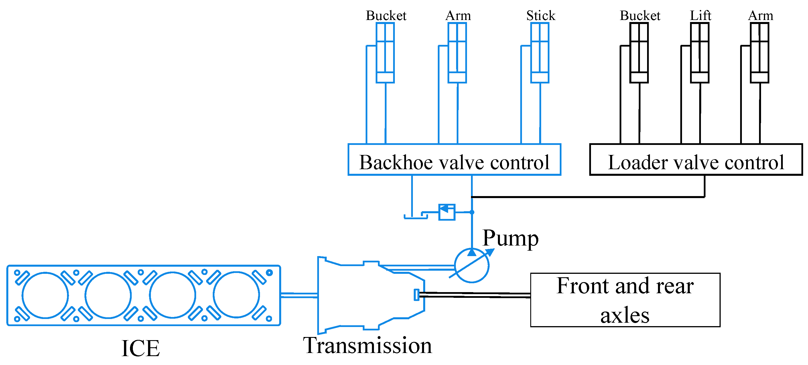
3.1. Traditional Architecture

Figure 3 exhibits the diesel-powered systems of the backhoe loader, and the highlighted equipment are going to be the electrified system in this work. In Figure 4, a block diagram depicting the traditional machine is provided. This diagram illustrates the operation of the implements by activating the cylinders. The diagram commences with the drive cycle block, which represents hydraulic power ( P h y d [kW]) during operation. Given that the pump operates at a constant rotational speed ( n n o m [rpm]), the reference torque ( T R e f ) is then defined.
One of the contributions of this work is to outline the methodology for defining performance maps, such as the pedal map and brake-specific fuel consumption for modeling internal combustion engines. This is particularly valuable, as manufacturers often do not disclose this information to the public. These maps are integrated into the simulation as lookup tables, allowing for the calculation of fuel consumption ( F C [g]) during a real drive cycle.

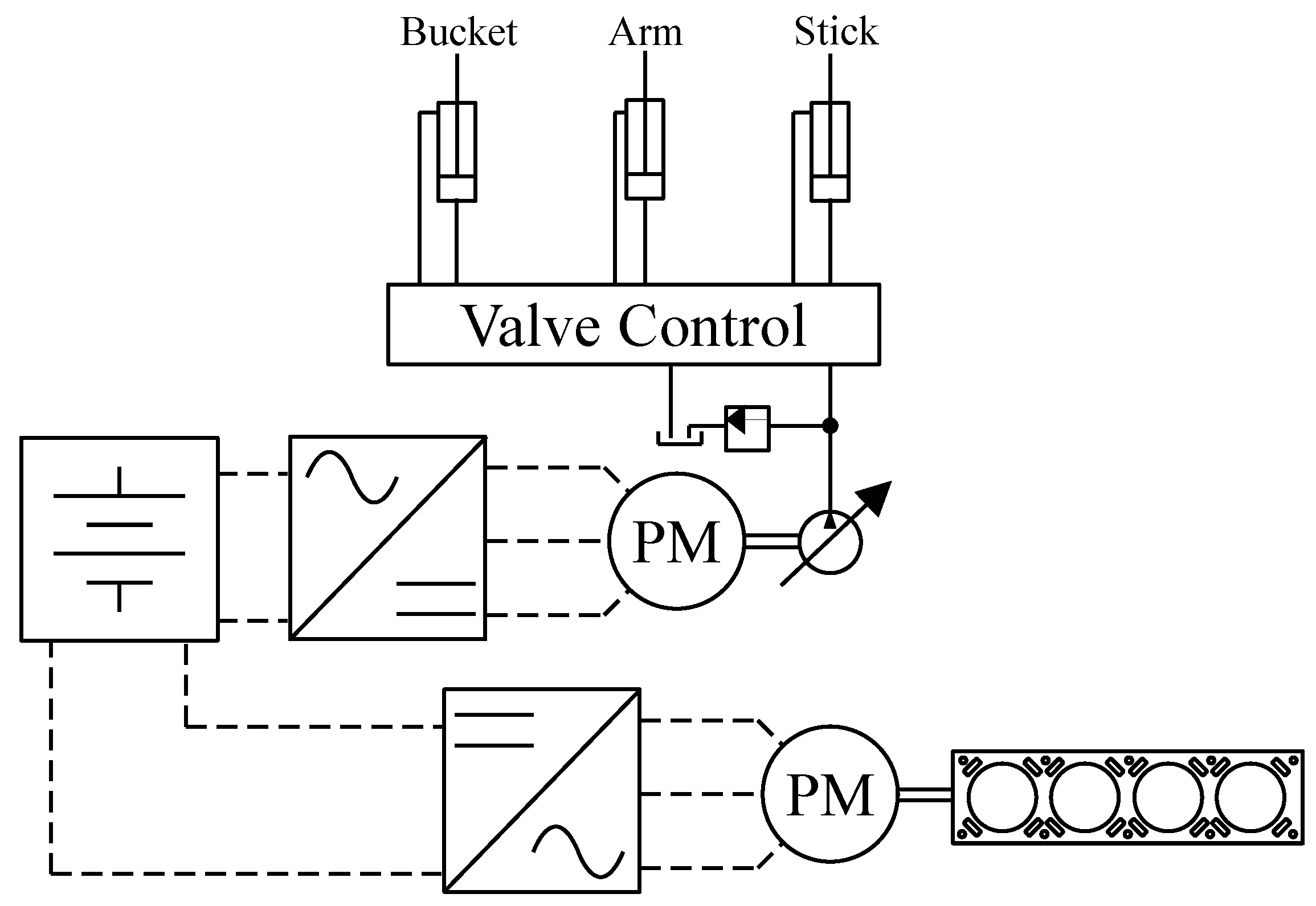
3.2. Hybrid Architecture

Figure 2 depicts the hybrid architecture schema adopted in this study for the electrification of the backhoe implement. In this configuration, the hydraulic pump is mechanically disconnected from the internal combustion engine, and the former connection is replaced by an electrical connection. The complete decoupling between the internal combustion engine and the hydraulic load is one of the benefits of this topology, allowing the ICE to operate at more efficient points of its fuel consumption map, thereby reducing fuel consumption during machine operation.
Figure 5 illustrates the block diagram of the hybrid backhoe loader. The key systems in this machine include the generator system (Genset), the drive system of the rear implement, represented by an electric motor (EM), and the energy management system.
Upon analyzing the generator system, it is observed that the internal combustion engine (ICE), connected to the electric machine shaft, receives inputs of the actual rotational speed ( n shaft ) and the position of the acceleration joystick ( J o y s t i c k ). Subsequently, the actual torque ( T ( i c e ) ) of the ICE is calculated via a modeled lookup table containing the pedal map. Utilizing the torque and speed values as inputs for the brake-specific fuel consumption map (obtained experimentally), the fuel consumption (FC) of the Diesel engine during the prototype’s operation is computed as one of the model’s outputs.
The electric machine, represented as a torque converter, is modeled according to its efficiency map, whose model will also be obtained and applied as a lookup table. In applications like this, the electric machines are controlled by a frequency inverter, whose losses are minimum due to the high efficiency of power converters [35]. Thus, this equipment was modeled with a constant gain of 96%. The dynamics of the coupling shaft ( n shaft ) were modeled, as presented by the subtraction node in Figure 5 and by Equation (1).
n shaft = T em T load ( b system · n shaft · π 30 ) J system d t
where J system is the rotational inertia of the combined system where the machine is mounted, b system is the viscous friction of the combined system, T em is the electromagnetic torque, and T load is the torque load on the shaft. The electromagnetic torque ( T gen ) from the generator is calculated from the reference torque ( T gen , ref ) ; the electric machine’s electric power ( P gen ) and efficiency (Eff) are outputs of the Genset system.
The energy management system uses the generator power input ( P gen ) and motor power input ( P em ) to calculate the electrical power of the direct current bus ( P d c , b u s ) and to determine in which state the machine will operate. To make this decision, the system also receives information about the bank’s terminal output voltage and state of charge ( S o C ). As another output, the system determines which current ( i b a t t ) should be in the DC bus.
The mechanical power ( P mec ) generated by the system is calculated according to Equation (2) [36], where T em is the electromagnetic torque and n gen is the generator speed. Hayes defines that the generator power output ( P gen ), which is flowing to the battery, can be expressed by the Equation (3):
P mec , gen = T em · n gen · ( π 30 )
P gen = P mec , gen · η ( gen , inv )
where η ( gen , inv ) is the efficiency of the generator and inverter combined. Another subsystem present in Figure 5 is the electric drive of the rear implement. This system performs the same activity the combustion backhoe model performs. That is, it must be capable of supplying the energy necessary to operate the hydraulic circuit according to the needs of the rear implement.
From Figure 5, the energy management system sets the reference speed n ref for the hydraulic drive according to the hydraulic power of the load. The speed control loop, defined in the local controller of the inverter, defines the reference torque T ( em ref ) . The current speed of the machine n em is also determined according to Equation (1), where the electromagnetic torque ( T em ) of the machine is subtracted from the load torque T load , along with a portion of the viscous friction b. Additionally, key variables include P h y d , representing hydraulic power, n n o m , denoting the speed of the hydraulic pump, J, indicating the rotational inertia of the system, E f f , representing the engine efficiency, and P em , signifying the power of the electric motor.
The electric machine was modeled as described earlier, functioning as a single torque source and utilizing the efficiency map shown in Figure 5 to calculate the system efficiency. Moreover, the dynamics of the coupling shaft (of the pump and EM) were modeled as presented by Equation (1). Unlike the generation system, for the electrical drive presented, a speed control loop was designed to guarantee operation under the reference of the management system: the nominal speed of the hydraulic pump.
The mechanical power ( P mec em ) generated by this system is also calculated according to Equation (4), where T em is the electric motor torque and ω em is the electric motor speed. The electrical power input ( P em ) to the motor, which is flowing from the battery, can be expressed by the Equation (5):
P mec , em = T em · ω e m
P em = P mec , em · η ( em )
where η ( em ) is the efficiency of the motor. An energy management system is necessary to ensure that the power flow in the machine among different sources occurs according to the operator’s needs and will be explained in the following sections.

4. Hybrid Compact Non-Road Mobile Machine Characterization

A backhoe loader was chosen to identify the positives and negatives points in the design of a hybrid compact non-road mobile machine. This vehicle is one of the more versatile compact NRMMs, which makes it more attractive to manufacturers. For instance, the backhoe loader market is projected to grow at a healthy growth rate of 8.8% compound annual growth rate from 2023 to 2030 [37]. As mentioned, the defined architecture is a hybrid series topology. As per the working assumptions for this project, the Diesel engine will be retained, and two permanent magnet synchronous machines will be employed as the motor and generator, powered by a pack of batteries. The chosen methodology for energy management is the rule-based on/off strategy, selected for its reliability and simplicity.

4.1. Characterization of the Backhoe Loader

As previously mentioned, a commercial backhoe loader, Figure 6, is the machine defined for this work. In general terms, the backhoe is one of the most versatile types of construction equipment, as it is a tractor that has a bucket at the front and another bucket at the rear. The front bucket can perform the most diverse tasks in construction, such as: transporting various materials to construction sites, leveling the ground, loading trucks, and removing debris and other objects. The rear bucket’s main functions are to demolish walls, columns, and other types of constructions, dig ditches, and holes and lay pipes. Table 5 presents the characteristics of the analyzed backhoe loader.

Hydraulic System

The backhoe’s hydraulic system is a load-sensing and load-sharing circuit that works with a hydraulic gear pump and system flow control valves, as portrayed in Figure 3. One advantage of using this type of system is that the flow distribution for the implements in operation is proportional to the activation of the control valve spools. Furthermore, this distribution is independent of the load, enabling the operation of two or more spools simultaneously.
The Diesel engine drives the hydraulic pump, thus allowing the oil to flow from the reservoir to the system. The hydraulic pump commonly present in loaders has a fixed displacement ( D v ), which means that the oil flow (Q) is proportional to the engine speed ( ω ), represented by Equation (6) [38]. The movement of the gears creates a pressure difference necessary to start the circulation of a fixed amount of oil between the hydraulic tank and the two control valves of the vehicle.
Q = ω D v

4.2. Drive Cycle

Light and heavy road vehicles have extensive literature, tests, and well-defined driving cycles, such as the FTP urban cycle, HWFET road cycle for light vehicles, and the LA92 cycle for heavy-weight vehicles [39]. Similarly, traction non-road duty cycles are also determined by the Environmental Protection Agency of the United States [40]. However, since the focus of this work is the operation of the implements, it was necessary to conduct experimental tests reproducing these operations.
During the operation of a backhoe loader, the main activities are trenching, basement excavation, loader stockpile, and roading. Trenching is one of the most frequent operations of a backhoe loader, as presented in Table 6 [31]. By analyzing the table, it was possible to establish that the machine performs activities with the backhoe bucket (trenching and basement excavation) for more than half of its operating time. The trenching cycle was then the selected activity for the continuity of the work due to its relevance in the context ofnthe equipment.
The trenching operation consists of digging a ditch with defined length, breadth, and depth, forming a narrow opening in the ground, while the machine is standing still. In this operation, all the oil flows from the oil tank to the hydraulic pump and the backhoe control valve to drive the rear cylinders.
After determining the operations performed by the backhoe loader, experimental tests were conducted to characterize the power profile. Yuan proposed a methodology for duty cycle development [41]. The data were acquired using pressure sensors, inductive sensors, a precision scale, and a data acquisition system during representative tests of the analyzed work cycle. To simulate the force exerted during excavation, the backhoe bucket was closed with a standard weight, and the operator repeated the excavation cycle multiple times over one hour. Mendes presented the correlation between the excavation movement and the hydraulic power of the work cycle [31].
The hydraulic power is determined by Equation (7) and is illustrated in Figure 7. Significant power fluctuations were observed within a few seconds, alongside measurement noise in the acquired signals. Consequently, an alternative drive cycle is also provided in Figure 7 to mitigate these issues.
P o u t = Δ p Q η t 600
where Δ p represents the pressure difference in the hydraulic line corresponding to the load, η t denotes the overall system efficiency, and Q represents the oil flow in the line.
A theoretical duty cycle, derived from the average value of the peaks observed during the trenching operation in Figure 7, eliminates signal vibrations in the data. Its significance lies in maintaining consistent values during the operation of the arm, swing, and bucket cylinders, thereby facilitating result analysis. Upon scrutinizing Figure 7, during the work cycles, the hydraulic system consumes an average power of approximately 12.95 kW for the experimental cycle and 11.55 kW for the theoretical cycle. The determined operating speed of the Diesel engine to meet the demanded load remained practically constant at 1800 rpm throughout the excavation period. This characterization provides a foundation for determining the system’s control strategies for the hybridization project.

4.3. Engine, Electrical Machine, and Energy Store System Model

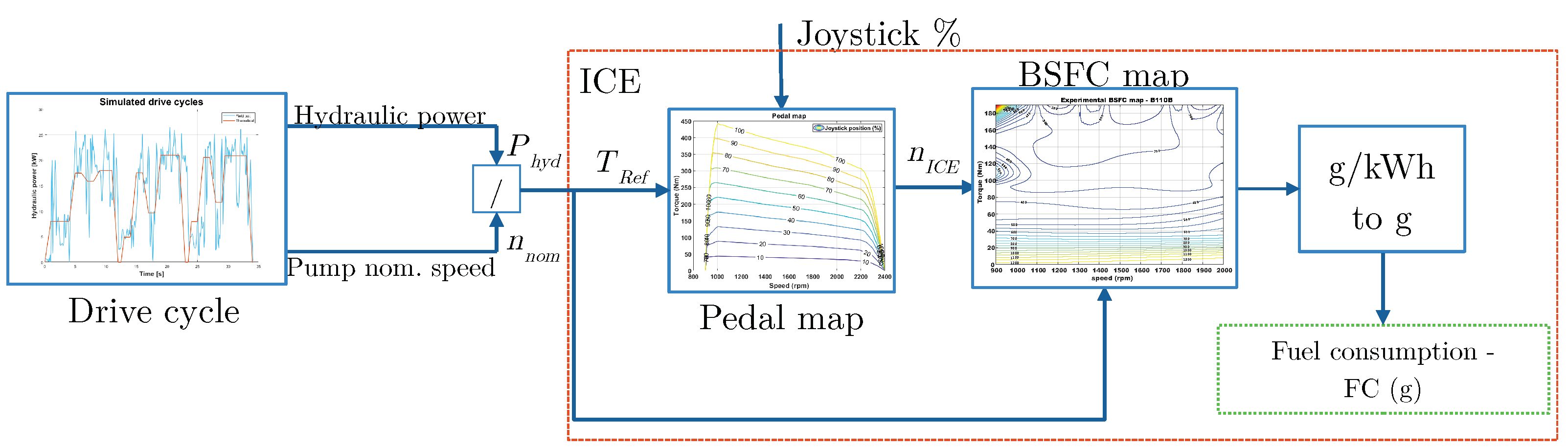
4.3.1. Internal Combustion Engine

It is possible to model the ICE considering various methodologies, depending on the required level of detailing for the simulation. The model may be steady state, quasi-steady, or dynamic [42]. Kulikov et al. presented a quasi-static approach in [43] to simulate a Diesel engine. The article’s performance maps, modeled as lookup tables, represented engine characteristics obtained experimentally in steady operating regimes. These characteristics were acquired via laboratory dynamometer tests, where several parameters, namely, the shaft speed, torque, and fuel consumption, were measured and logged. To define the ICE performance maps for the simulation, this approach was adopted. The engine characteristics were obtained from both data provided by the manufacturer in operating regimes and from experimental tests.
The Diesel engine in the backhoe loader is mechanically connected to the hydraulic pump. Consequently, the engine’s speed is dictated by the fixed nominal speed of the pump during operation. In the selected backhoe loader for the case study, there is no speed control loop (governor). Therefore, the engine’s setpoint reference is determined by a pedal map, illustrated in Figure 8. This map interpolates the gross net torque curve as a function of speed. Since this curve represents the limiting condition for engine operation, it was chosen as the point at which engine acceleration is maximum. Idle points of the machine were considered to be under conditions of null acceleration.
The next performance map used in the Diesel engine model is the brake-specific fuel consumption (BSFC) map. It represents the engine’s specific fuel consumption as a function of the actual torque, T r e f , and speed of the shaft, n I C E , Equation (8). These maps are usually classified information but can be defined through engine tests conducted on a dynamometer. The performed test involves applying load steps to the engine, acquiring the speed behavior, and acquiring the fuel consumption at each applied load point. The access to a dynamometer capable of performing this test in an off-road machine is often scarce. Therefore, this characterizing test can also be performed with the hybrid non-road mobile machine. The generator works as reference load setter for the internal combustion engine. The speed and the fuel consumption are also acquired. After the test, the experimental points are interpolated to generate a map capable of determining the fuel consumption during trenching operation.
B S F C = f ( r p m , T r e f ) = F C P m 3600
where BSFC represents the brake-specific fuel consumption in grams per kilowatt-hour (g/kWh), P m denotes the mechanical power of the engine shaft in kilowatts (kW), and FC stands for the fuel consumption in grams per hour (g/h). However, as it is conventionally preferred to express fuel consumption in liters per hour (L/h), the new equation for fuel consumption is expressed as shown in Equation (9), where the diesel density is considered to be 0.853 kg/L. It is noteworthy that both maps also incorporate the maximum torque curve with respect to speed to limit the reference torque sent by the controller. In this case, the reference torque is derived from the driving cycle.
F C l / h = F C 853 3600

4.3.2. Electric Machine

The electric machines (generator and motor) defined for the system are the EMRAX 228 LV [32]. They are represented by dynamical or quasi-static models. The quasi-static approach uses efficiency maps to reflect losses during operation. This method provides an opportunity to reduce computational time, while achieving sufficient accuracy for the modeling of hybridized systems [44]. Following the methodology of the previous section, the efficiency maps were interpolated from the datasheet of the electric machine [45]. The efficiency map, shown in Figure 9, is coupled with the maximum torque curve in this approach.

4.3.3. Energy Storage System

The other energy source is the energy storage system, which is fundamental when considering the hybridization of any type of vehicle. In this context, batteries and supercapacitors are possible electrical energy storage solutions. Batteries have the highest energy density, while supercapacitors have a high power density. For this design, batteries were chosen, and their design characteristics are defined in the work presented by Brandão et al. [32]. Table 7 presents battery bank parameters.
The chosen path was to define the adequate option from Simulink’s library. Since the system’s characteristics were previously known, the estimation-equivalent circuit battery was the specified one due to its lookup table characteristics [46]. The model implements a resistor–capacitor (RC) equivalent circuit of the battery, based on manufacturer data. Lookup tables are used to represent variables, such as series resistance and battery open-circuit voltage, as functions of the state-of-charge (SoC). Equation (10) represents how the model calculates the battery’s state of charge. C b a t t is the pack capacity, and I b a t t is the current flowing in and out of the battery whenever the system charges or discharges, respectively.
SOC = 1 C batt 0 t I batt d t
In addition to determining the state of charge according to the variation of I b a t t , the block also determines the bank’s output voltage ( V o u t ) based on information from the cell manufacturer. The rate between the power in the direct current (DC) bus (generated power or requested power by the drive system) and the terminal voltage of the battery is the equation used to calculate I b a t t (Equation (11)), where P d c , b u s is the power on a DC bus and V o u t is the bank’s output voltage. This current is the variable used as input for the energy storage system model.
I b a t t = P d c , b u s / V o u t

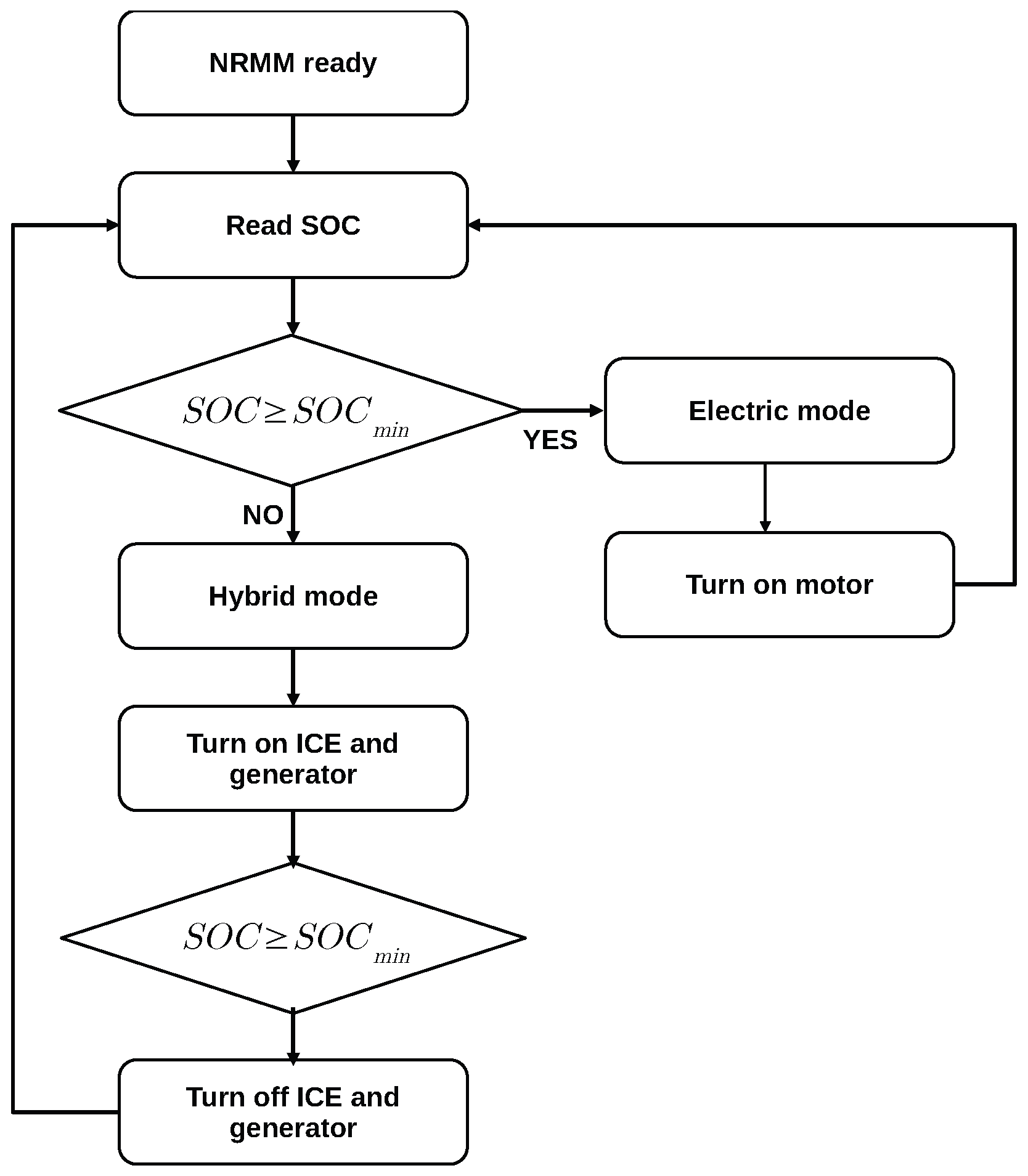
4.4. Energy Management System

The main point of this electrification project is related to the most appropriate determination of how to use the two energy sources present in the machine: the fuel tank and the battery. The energy management system needs to receive vehicle control variables to determine the optimal working points of the generator set and engine system in conjunction with the hydraulic pump. This analysis requires a proper power-management strategy to handle the controlled systems’ working points. Since this is an initial stage of the hybridization project applied to a compact non-road mobile machine, it was preferable to consider a simplified rule-based charge-depleting strategy combined with the on/off.
The constraints from the Diesel engine (speed and torque) and the electrical machines are important in defining the boundaries for the system. The state of charge is also one of the most essential parameters for the vehicle since it can potentially provide information regarding the autonomy of the machine via the amount of energy stored in the battery. In order to improve the storage system life, the state of charge should be controlled between the maximum (90%) and minimum (40%) limits. The rules implemented for the hybrid driving mode were as follows:
0 T i c e T i c e , m a x ω i c e , i d l e ω i c e , g e n ω i c e , m a x 0 T g e n T g e n , m a x 0 T e m T e m , m a x 0 ω e m ω e m , m a x S o C m i n S o C S o C m a x
where T i c e is the ICE torque, T i c e , m a x is the ICE max torque, ω i c e , i d l e is the ICE speed in idle condition, ω i c e , g e n is the generator speed, and ω i c e , m a x is the ICE max speed. This methodology was the best choice, considering that it is a strategy widely used in the literature and a frequently applied approach in a series of hybrid road vehicles. Heuristic systems are based on prior knowledge of the vehicle’s operating conditions. In the on/off strategy, Figure 10, the ICE is turned off when the machine is performing the trenching cycle. When the capacity comes near a preset minimum limit, the engine is turned on to charge the pack of batteries.
Figure 11 illustrates the state machine implemented in the controller of the energy management system. Upon analyzing the figure, the presence of two states becomes noteworthy: electric and hybrid modes. First, the controller reads the state of the state of charge from the ESS. If this value exceeds the minimum limit, the machine can operate in its motorization mode. In this condition, the controller sends the speed reference to the motorization inverter, which then defines the setpoints of the electric motor coupled to the hydraulic pump. This is the process followed by the controller to keep the hydraulic system performing in nominal condition and delivering the necessary power to the load without losing performance.
If the state of charge value exceeds the defined minimum limit, the system enters its hybrid mode, where the Genset receives the enable signal from the controller. At this point, the controller is also responsible for sending the T r e f signal to the system. This reference value must be equivalent to the minimum brake fuel consumption according to the BSFC map to ensure that the ICE is, indeed, operating at the best configuration. As previously illustrated, this point is near the maximum torque limit. Therefore, the implemented strategy allows the Diesel engine to reach higher efficiency when compared to the traditional operation. The system will remain in this condition, preventing the state machine from entering the motorization operating condition until the energy storage system completes its load; at this point, the state machine returns to its initial point of reading the state of charge.

5. Discussion and Results

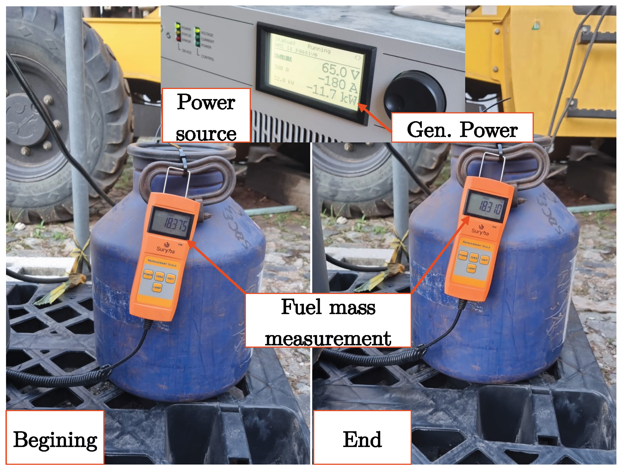
5.1. Experimental Tests

The experimental tests performed in the hybrid backhoe loader were divided into:
  • Operation of the generator;
  • Operation of the electric drive of the rear implement.
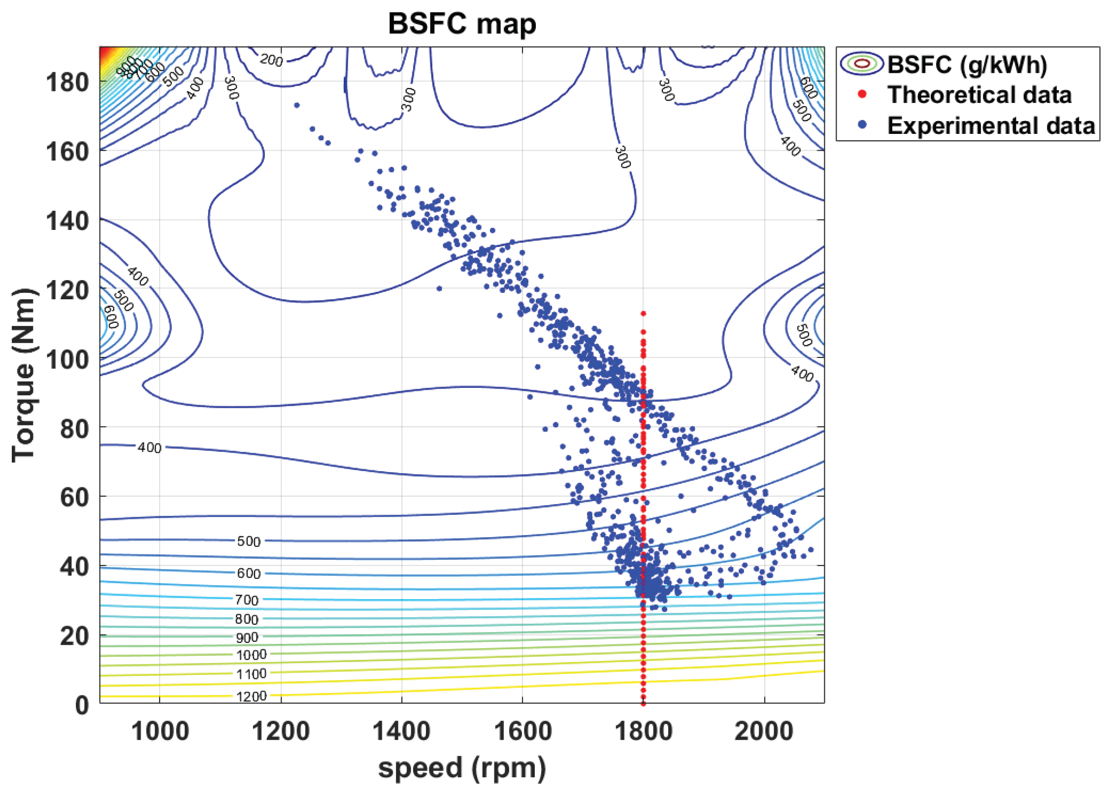
The initial test aimed to assess the performance of the generation system. It involved applying various torque steps (acting as braking loads) to the ICE shaft, ranging from the minimum to the maximum value. Additionally, the engine’s rotational speed was varied from idle to the maximum value. At each operating point, the fuel consumption rate (FC) in grams per second (g/s) was measured using a precision scale. The test setup is illustrated in Figure 12. Through the acquired data of this test, the characteristic brake-specific fuel consumption map of the backhoe loader, depicted in Figure 13, was defined.
At this juncture, it is important to highlight that the test to define the brake-specific fuel consumption map of the Diesel engine of the backhoe loader under study was conducted with certain limitations. The generator specified by Brandão et al. [32], utilized for the analysis in this study, has a continuous torque value of 120 Nm and a maximum peak of 230 Nm in its speed–torque curve. Therefore, if the map is extrapolated with limits considering the maximum torque curve as a function of the internal combustion engine speed depicted in Figure 8, isocurves that exhibit better fuel consumption points may be identified.
The next experimental test was the operation of the trenching cycle with the hybrid backhoe loader to certify whether, performance-wise, there would be any difference. Figure 14 presents the test setup that was performed by a professional backhoe loader operator. The drive cycle defined in Figure 7 was acquired when the machine was operating in both topologies.

5.2. Simulations

Both topologies were simulated in a MATLAB R2021b environment, as illustrated in Section 3. The hybridization design project used as a basis for this work is the one developed by Brandão et al. [32]. The test conditions were equally replicated for both topologies for the convenience of comparison.
Figure 15 and Figure 16 represent the BSFC results for the conventional architecture and the accumulated fuel consumption for the trenching drive cycle for both architectures, respectively. Figure 17 illustrates the operating points on the efficiency maps during the simulation of the hybrid operation.
Some considerations are important regarding the presented results. The internal combustion engine, when maintained in its traditional configuration, began to operate in an oversized manner. This is a consequence of the mechanical decoupling of the hydraulic pump, wherein the equipment is no longer responsible for supplying hydraulic power to the rear implement. When operated in conjunction with the generator at its point of minimum brake specific fuel consumption, the engine is no longer stressed under high torque conditions at a constant speed. The optimal point simulated in this work had as T g e n , r e f 125 Nm, and the joystick constant was set to 36%. The actual simulated system velocity was 1762 rpm, and the corresponding BSFC was 304.75 g/kWh.
This condition contrasts with the simulation of the traditional architecture of the backhoe loader. When analyzing Figure 15, it is noticeable how the machine’s operating points are dispersed on the map and concentrate in regions of worse BSFCs. Further comparing the results between the theoretical and experimental curves, the main difference lies in the profile of the two simulated cycles. The speed of the theoretical cycle is constant, equal to the nominal operating speed of the hydraulic pump.
The proposed topology has several distinct benefits compared to the traditional backhoe loader. Figure 16 displays the fuel usage of the two different systems for the same running cycle (in kilograms). The results are presented in Table 8. It is important to note that for the hybrid machine, there is a 16.32% difference between the two proposed cycles, whereas for the traditional topology, the difference is minimal (2.31%). Between the two different topologies, the proposed topology consumes significantly less fuel than the conventional commercial counterpart. There is a reduction of 21.99% in fuel consumption when the theoretical drive cycle was simulated. When the experimental data were applied, the reduction increased to 33.18%. These results are important because they were achieved without any performance downgrade during the trenching cycle. This improvement stems from the presence of the energy management system and the adopted topology. The operation of the internal combustion engine at a more efficient point is a consequence of the adopted series hybrid topology, while the utilization of the generation system at specific operation points to charge the energy storage system when necessary is a result of the implemented energy management system for the machine.
The energy management system is one of the main reasons why this improvement is possible. Figure 10 depicts the state of charge of the battery and the enable signal given to the Genset. Throughout the operation, there are constant charges and discharges of the battery, always occurring within the upper and lower limits of the battery state of charge. As can be seen, the battery is able to supply power to the motor and hydraulic system during periods of high power demand from Figure 7. With the series hybrid topology, the motor, generator, and internal combustion engine operating points during trenching are shown in Figure 17. The majority of the operational points have an efficiency of 82% to 94%, which is at least two times higher than what the Diesel engine is capable of delivering.
Fuel combustion is the trigger point for these machines’ high percentage of emissions. Regarding the proposed emissions assessment, it is safe to consider that it should also diminish with lesser usage of fossil fuels for the operation of the backhoe loader. It is important to recognize that the emissions are caused by fuel combustion. Nevertheless, this comparison is not linear. Therefore, performance maps should also be included in the ICE model for each desired emission analysis to achieve an accurate assessment. This modeling was not in this project’s scope since emissions mapping is more complicated and requires more complex equipment when compared to BSFC mapping.

6. Conclusions

A validation of the electrification design of a type of compact non-road mobile machinery is presented in this work. Firstly, the meaning and classifications of off-road vehicles were discussed, highlighting the possible different categorizations. The work then delved into the challenges and solutions documented in the literature, concerning the inherent emission problems associated with internal combustion engines. Additionally, the crucial components of a hybrid non-road mobile machine were outlined, and the modeling methods were explored. Finally, the study presented a computational model for the two architectures. The models were validated with data from experimental tests conducted before and after the modifications to the backhoe loader.
A commercial backhoe loader with 72 kW gross power and approximately 7 h of autonomy was used as a platform to analyze the feasibility of the electrification project. The preference for a hybrid architecture allowed the backhoe loader to perform the same drive cycle with improved drive system efficiency (94%) when compared to the internal combustion engine drive (40%). The tests and simulations conducted with the hybrid prototype have revealed that employing appropriate energy system management enables the attainment of the targeted reduction in fuel consumption. Moreover, by optimizing fuel utilization for the same tasks, emissions are correspondingly mitigated. The operation in the proposed theoretical drive cycle culminated in 21.99% less fuel consumption than a traditional backhoe loader and 33.18% less fuel when experimental data are applied. The Diesel engine’s operation solely as a generator enabled these improvements. The new operation point was defined as 125 Nm and 1800 rpm, a more optimal point in the efficiency map than the traditional combustion-only model.
The results showed a considerable improvement in fuel consumption and, consequently, in emissions. However, there is still room for future improvements. It is important to highlight that these results were obtained without any optimization performance algorithms, so there is still room to improve the operation of the energy management system. Moreover, since internal combustion engines in non-road machines are designed and dimensioned according to the peak power demands of various activities they perform, a downsizing project would lead to more significant results. An engine with a lesser-rated power has its minimum brake-specific fuel consumption in smaller load conditions than the engine of the analyzed backhoe. The smaller the needed torque, the higher the compatibility with the generator, enhancing overall efficiency. Furthermore, the drive of the backhoe’s rear arm cylinders remained with a main hydraulic pump. The cost of replacing the hydraulic pump with electrical drives sized for each hydraulic cylinder is high and exceeds the project’s budgetary assumptions. Therefore, there is room for further efficiency gains if the design constraints are more flexible.
A proper energy management system design is essential for the improvements acquired by the electrification of the implements in non-road machines. The aim to reduce fuel consumption and, consequently, emissions from fuel combustion is achievable from the adequate choice of the control strategies combined with optimization. The improvements achieved by selecting operating strategies are possible up to a maximum point. Hence, for future works, it would be advantageous to explore various configurations of energy management systems. This involves implementing optimization algorithms to fine-tune the decisions of torque, speed, and the corresponding points of the brake-specific fuel consumption map, thereby identifying the most suitable decisions in real time. Such optimizations hold promise for maximizing efficiency when deploying the machine’s dual energy storage systems.

Author Contributions

Conceptualization, M.d.F.R. and D.A.d.L.B.; methodology, M.d.F.R., D.A.d.L.B., and T.A.C.M.; software, M.d.F.R.; validation, M.d.F.R., D.P.V.G., and T.A.C.M.; formal analysis, M.d.F.R. and D.A.d.L.B.; investigation, M.d.F.R., D.A.d.L.B., and D.P.V.G.; resources, D.P.V.G., I.A.P., B.d.J.C.F., and T.A.C.M.; data curation, M.d.F.R.; writing—original draft preparation, M.d.F.R.; writing—review and editing, M.d.F.R. and T.A.C.M.; visualization, M.d.F.R. and D.A.d.L.B.; supervision, I.A.P., B.d.J.C.F., and T.A.C.M.; project administration, D.P.V.G., I.A.P., B.d.J.C.F., and T.A.C.M.; funding acquisition, I.A.P., B.d.J.C.F., and T.A.C.M. All authors have read and agreed to the published version of the manuscript.

Funding

This research was funded by Fundação de Desenvolvimento da Pesquisa (FUNDEP)—Rota 2030/Linha V, grant number 27192.03.01/2020.15-00.

Institutional Review Board Statement

Not applicable.

Informed Consent Statement

Not applicable.

Data Availability Statement

The original contributions presented in the study are included in the article, further inquiries can be directed to the corresponding author.

Acknowledgments

This work was also supported by the Coordenação de Aperfeiçoamento de Pessoal de Nível Superior (CAPES), by the Conselho Nacional de Desenvolvimento Científico e Tecnológico (CNPq), and by the Fundação de Amparo à Pesquisa do Estado de Minas Gerais (FAPEMIG).

Conflicts of Interest

Diogo P. V. Galo is employee of CNH Industrial. The paper reflects the views of the scientists, and not the company.

Abbreviations

The following abbreviations are used in this manuscript:
BSFCBrake-specific fuel consumption
CCompact
COCarbon monoxides
DCDirect current
ELExtra-large
FCFuel consumption
FTPFederal Test Procedure
GensetGeneration system
HCHydrocarbons
HWFETHighway Fuel Economy Test Cycle
ICEInternal combustion engine
LLarge
LA92EPA—California unified cycle
MMedium
MiMini
N O x Nitrogen oxides
NRMMNon-road mobile machine
SSmall
SoCState of charge

References

  1. U.S. Department of Transportation, The Transportation Future: Trends, Transportation, and Travel. The Transportation Future: Trends, Transportation, and Travel Transportation Policy Study Topics. 2021. Available online: https://www.fhwa.dot.gov/policy/otps/TPS_2020_Trends_Report.pdf (accessed on 4 January 2024).
  2. European Commission. Non-Road Mobile Machinery Emissions. 2020. Available online: https://ec.europa.eu/growth/sectors/automotive/environment-protection/non-road-mobile-machinery_en (accessed on 17 December 2023).
  3. Hagan, R.; Markey, E.; Clancy, J.; Keating, M.; Donnelly, A.; O’Connor, D.J.; Morrison, L.; McGillicuddy, E.J. Non-Road Mobile Machinery Emissions and Regulations: A Review. Air 2023, 1, 14–36. [Google Scholar] [CrossRef]
  4. Beltrami, D.; Iora, P.; Tribioli, L.; Uberti, S. Electrification of Compact Off-Highway Vehicles—Overview of the Current State of the Art and Trends. Energies 2021, 14, 5565. [Google Scholar] [CrossRef]
  5. Brenna, M.; Foiadelli, F.; Leone, C.; Longo, M.; Zaninelli, D. Feasibility Proposal for Heavy Duty Farm Tractor. In Proceedings of the 2018 International Conference of Electrical and Electronic Technologies for Automotive, Milan, Italy, 9–11 July 2018; pp. 1–6. [Google Scholar] [CrossRef]
  6. Un-Noor, F.; Scora, G.; Wu, G.; Boriboonsomsin, K.; Perugu, H.; Collier, S.; Yoon, S. Operational Feasibility Assessment of Battery Electric Construction Equipment Based on In-Use Activity Data. Transp. Res. Rec. 2021, 2675, 809–820. [Google Scholar] [CrossRef]
  7. Vu, N.-L.; Messier, P.; Nguyen, B.-H.; Vo-Duy, T.; Trovão, J.P.F.; Desrochers, A.; Rodrigues, A. Energy-optimization design and management strategy for hybrid electric non-road mobile machinery: A case study of snowblower. Energy 2023, 284, 129249. [Google Scholar] [CrossRef]
  8. Troncon, D.; Alberti, L.; Mattetti, M. A Feasibility Study for Agriculture Tractors Electrification: Duty Cycles Simulation and Consumption Comparison. In Proceedings of the 2019 IEEE Transportation Electrification Conference and Expo (ITEC), Detroit, MI, USA, 19–21 June 2019; pp. 1–6. [Google Scholar] [CrossRef]
  9. Grammatico, S.; Balluchi, A.; Cosoli, E. A series-parallel hybrid electric powertrain for industrial vehicles. In Proceedings of the 2010 IEEE Vehicle Power and Propulsion Conference, Lille, France, 1–3 September 2010; pp. 1–6. [Google Scholar] [CrossRef]
  10. Somà, A. Trends and Hybridization Factor for Heavy-Duty Working Vehicles. In Hybrid Electric Vehicles; InTech: London, UK, 2017; pp. 3–32. [Google Scholar] [CrossRef]
  11. Wang, H.; Wang, Q.; Hu, B. A review of developments in energy storage systems for hybrid excavators. Autom. Constr. 2017, 80, 1–10. [Google Scholar] [CrossRef]
  12. Dalboni, M.; Santarelli, P.; Patroncini, P.; Soldati, A.; Concari, C.; Lusignani, D. Electrification of a Compact Agricultural Tractor: A Successful Case Study. In Proceedings of the 2019 IEEE Transportation Electrification Conference and Expo (ITEC), Detroit, MI, USA, 19–21 June 2019; pp. 1–6. [Google Scholar] [CrossRef]
  13. Mattarelli, E.; Rinaldini, C.A.; Scrignoli, F.; Fregni, P.; Gaioli, S.; Franceschini, G.; Barater, D. Potential of Electrification Applied to Non-Road Diesel Engines (SAE Technical Paper No. 2019-24-0202); SAE International: Warrendale, PA, USA, 2019. [Google Scholar] [CrossRef]
  14. Moreira, W.K. Análise e Projeto de Sistemas de Propulsão híBridos para Tratores agríColas. Analysis and Design of Hybrid Propulsion Systems for Agricultural Tractors; Universidade Federal de Santa Maria. 2022. Available online: http://repositorio.ufsm.br/handle/1/27052 (accessed on 31 August 2022).
  15. Lajunen, A. Simulation of energy efficiency and performance of electrified powertrains in agricultural tractors. In Proceedings of the 2022 IEEE Vehicle Power and Propulsion Conference (VPPC), Merced, CA, USA, 1–4 November 2022; pp. 1–6. [Google Scholar] [CrossRef]
  16. Zhang, B.; Guo, S.; Zhang, X.; Xue, Q.; Teng, L. Adaptive Smoothing Power Following Control Strategy Based on an Optimal Efficiency Map for a Hybrid Electric Tracked Vehicle. Energies 2020, 13, 1893. [Google Scholar] [CrossRef]
  17. Wen, Q.; Wang, F.; Xu, B.; Sun, Z. Improving the Fuel Efficiency of Compact Wheel Loader With a Series Hydraulic Hybrid Powertrain. IEEE Trans. Veh. Technol. 2020, 69, 10700–10709. [Google Scholar] [CrossRef]
  18. Cunanan, C.; Tran, M.-K.; Lee, Y.; Kwok, S.; Leung, V.; Fowler, M. A Review of Heavy-Duty Vehicle Powertrain Technologies: Diesel Engine Vehicles, Battery Electric Vehicles, and Hydrogen Fuel Cell Electric Vehicles. Clean Technol. 2021, 3, 474–489. [Google Scholar] [CrossRef]
  19. Mocera, F.; Somà, A. Analysis of a Parallel Hybrid Electric Tractor for Agricultural Applications. Energies 2020, 13, 3055. [Google Scholar] [CrossRef]
  20. Padovani, D.; Dimitriou, P.; Minav, T. Challenges and solutions for designing Energy-Efficient and Low-Pollutant Machines in Off-Road hydraulics. Energy Convers. Manag. X 2024, 21, 100526. [Google Scholar] [CrossRef]
  21. Mendes, F.E.G.; Brandao, D.I.; Maia, T.; de Filho, J.C.B. Off-Road Vehicle Hybridization Methodology Applied to a Tractor Backhoe Loader. In Proceedings of the IEEE Transportation Electrification Conference and Expo (ITEC), Detroit, MI, USA, 19–21 June 2019; pp. 1–6. [Google Scholar]
  22. Do, T.C.; Truong, H.V.A.; Dao, H.V.; Ho, C.M.; To, X.D.; Dang, T.D.; Ahn, K.K. Energy Management Strategy of a PEM Fuel Cell Excavator with a Supercapacitor/Battery Hybrid Power Source. Energies 2019, 12, 4362. [Google Scholar] [CrossRef]
  23. Wang, D.; Guan, C.; Pan, S.; Zhang, M.; Lin, X. Performance analysis of hydraulic excavator powertrain hybridization. Autom. Constr. 2009, 18, 249–257. [Google Scholar] [CrossRef]
  24. Vehicle, Cambridge Dictionary. 2023. Available online: https://dictionary.cambridge.org/dictionary/english/vehicle (accessed on 17 December 2023).
  25. Lajunen, A.; Sainio, P.; Laurila, L.; Pippuri-Mäkeläinen, J.; Tammi, K. Overview of Powertrain Electrification and Future Scenarios for Non-Road Mobile Machinery. Energies 2018, 11, 1184. [Google Scholar] [CrossRef]
  26. Lajunen, A.; Suomela, J.; Pippuri, J.; Tammi, K.; Lehmuspelto, T.; Sainio, P. Electric and Hybrid Electric Non-Road Mobile Machinery—Present Situation and Future Trends. World Electr. Veh. J. 2016, 8, 172–183. [Google Scholar] [CrossRef]
  27. Dallmann, T.; Menon, A. Technology Pathways for Diesel Engines Used in Non-Road Vehicles And Equipment; The International Council on Clean Transportation: Washington, DC, USA, 2016. [Google Scholar]
  28. Equipments, Caterpillar. 2023. Available online: https://www.cat.com/en_US/products/new/equipment.html (accessed on 17 December 2023).
  29. Olson, E. Engineering 360. How the World’s First Large-Scale Electric Excavator Works. In July 2019. Available online: https://cutt.ly/wbP2Qdq (accessed on 5 May 2021).
  30. CNHi; Case Construction. CASE Unveils “Project Zeus”—The All-New 580 EV—The Industry’s First Fully Electric Backhoe Loader. 2020. Available online: https://cutt.ly/HbDzkxl (accessed on 30 April 2021).
  31. Mendes, F.E.G. Electrificação de Máquinas Pesadas Fora de Estrada Baseada no Acionamento Elétrico dos Atuadores e Armazenadores de Energia de Baixa Capacidade. Master’s Thesis, Universidade Federal de Minas Gerais, Minas Gerais, Brazil, 21 November 2019. [Google Scholar]
  32. Brandao, D.A.d.L.; Ramos, M.d.F.; Parreiras, T.M.; Maia, T.A.C.; Pires, I.A.; Corrêa, T.P.; Cardoso Filho, B.d.J.; Nascimento, A. Hybridization of a Backhoe Loader: Electric Drive System Design. Machines 2023, 11, 471. [Google Scholar] [CrossRef]
  33. Vukovic, M.; Leifeld, R.; Murrenhoff, H. Reducing Fuel Consumption in Hydraulic Excavators—A Comprehensive Analysis. Energies 2017, 10, 687. [Google Scholar] [CrossRef]
  34. Taherzadeh, E.; Dabbaghjamanesh, M.; Gitizadeh, M.; Rahideh, A. A New Efficient Fuel Optimization in Blended Charge Depletion/Charge Sustenance Control Strategy for Plug-In Hybrid Electric Vehicles. IEEE Trans. Intell. Veh. 2018, 3, 374–383. [Google Scholar] [CrossRef]
  35. Brandao, D.A.D.L.; Ramos, M.D.F.; Pires, I.A.; Maia, T.A.; Cardoso Filho, B.D.J. Impact of the Efficiency of Commercial Auxiliary Power Modules on Electric Vehicles. Congr. Bras. Automática 2022, 3, CBA2022. [Google Scholar] [CrossRef]
  36. Hayes, J.G.; Goodarzi, G.A. Electromobility and the Environment. In Electric Powertrain: Energy Systems, Power Electronics and Drives for Hybrid, Electric and Fuel Cell Vehicles, 1st ed.; John Wiley & Sons: Hoboken, NJ, USA, 2018; pp. 3–40. [Google Scholar]
  37. Backhoe Loaders Market Development and Its Factors Analysis-Product/Industry News-Xiamen LTMG Co., Ltd. Available online: https://www.ltmg-loader.com/news/industry-news/547.html (accessed on 28 November 2023).
  38. Hydraulic Gear Pumps and Motors. Available online: https://www.casappa.com/en/c/downloads/category/2/ (accessed on 30 August 2021).
  39. Vehicle and Fuel Emissions Testing—Dynamometer Drive Schedules. United States Environmental Protection Agency, EPA. Available online: https://www.epa.gov/vehicle-and-fuel-emissions-testing/dynamometer-drive-schedules/ (accessed on 6 November 2023).
  40. Us Epa, O. EPA Nonregulatory Nonroad Duty Cycles. 2017. Available online: https://www.epa.gov/moves/epa-nonregulatory-nonroad-duty-cycles (accessed on 5 February 2024).
  41. Yuan, Q. Real World Duty Cycle Development Method for Non-road Mobile Machinery (NRMM). SAE Int. J. Commer. Veh. 2016, 9, 306–312. [Google Scholar] [CrossRef]
  42. Mi, C.; Masrur, M.A.; Gao, D.W. Modeling and Simulation of Electric and Hybrid Vehicles. In Hybrid Electric Vehicles; John Wiley & Sons, Ltd.: Hoboken, NJ, USA, 2011; pp. 363–384. [Google Scholar] [CrossRef]
  43. Kulikov, I.; Kozlov, A.; Terenchenko, A.; Karpukhin, K. Comparative Study of Powertrain Hybridization for Heavy-Duty Vehicles Equipped with Diesel and Gas Engines. Energies 2020, 13, 2072. [Google Scholar] [CrossRef]
  44. Goswami, G.; Tupitsina, A.; Jaiswal, S.; Nutakor, C.; Lindh, T.; Sopanen, J. Comparison of Various Hybrid Electric Powertrains for Non-Road Mobile Machinery Using Real-Time Multibody Simulation. IEEE Access 2022, 10, 107631–107648. [Google Scholar] [CrossRef]
  45. EMRAX. Emrax E-Motors: 228 (124 kW | 230 Nm), n.d. Available online: https://emrax.com/e-motors/emrax-228/ (accessed on 5 February 2023).
  46. Estimation Equivalent Circuit Battery. MathWorks Help Center. Available online: https://www.mathworks.com/help/autoblks/ref/estimationequivalentcircuitbattery.html?s_tid=srchtitle_site_search_1_estimation%20equivalent%20circuit%20battery (accessed on 28 November 2023).
Figure 1. Examples of NRMM used for agriculture: New Holland TC harvester, Oxbo AR4BX harvester, and New Holland Powerstar 120 tractor.
Wevj 15 00127 g001
Figure 2. Series configuration applied to the implements of a backhoe.
Wevj 15 00127 g002
Figure 3. Traditional compact non-road machine scheme. The highlighted components in blue are the analyzed system.
Wevj 15 00127 g003
Figure 4. Block diagram of the traditional compact non-road machine hydraulic drive model.
Wevj 15 00127 g004
Figure 5. Block diagram of the hybrid compact non-road machine hydraulic drive model.
Wevj 15 00127 g005
Figure 6. Representation of the main components of the hydraulic system of a non-road mobile machine.
Wevj 15 00127 g006
Figure 7. Trenching drive cycle—experimental test (blue) and theoretical curve (orange).
Wevj 15 00127 g007
Figure 8. Theoretical graph of the torque x speed limit curve of a Diesel ICE built base.
Wevj 15 00127 g008
Figure 9. Efficiency map of the electric machine [45].
Wevj 15 00127 g009
Figure 10. On/off energy management strategy: SOC variation with ICE command.
Wevj 15 00127 g010
Figure 11. Controller state machine.
Wevj 15 00127 g011
Figure 12. Fuel mass and electrical parameter measurements from generation experimental test.
Wevj 15 00127 g012
Figure 13. Brake-specific fuel consumption map of a Diesel engine generated with experimental test data.
Wevj 15 00127 g013
Figure 14. Trenching experimental test performed with the hybrid backhoe loader.
Wevj 15 00127 g014
Figure 15. Operating points of the trenching cycle in the brake-specific fuel consumption map of the Diesel engine for the combustion architecture.
Wevj 15 00127 g015
Figure 16. Fuel consumption comparison between theoretical (orange) and experimental (blue) drive cycles for the combustion model.
Wevj 15 00127 g016
Figure 17. Hybrid model working points for electric motor efficiency map (left) and generator efficiency map (right).
Wevj 15 00127 g017
Table 1. Comparative analysis of adherent state-of-the-art works.
ReferenceMachinery
Type
Hybrid
Topology
Implements
Hybridization
ICE
Maps
Electric
Machines
Maps
Fuel
Comsumption
Experimental
Validation
[5]TractorFull Electric
[7]SnowblowerSeries
[8]TractorSeries
[23]ExcavatorSeries/Parallel
[9]Wheel LoaderSeries–Parallel
[12]TractorSeries
[13]ExcavatorParallel
[14]TractorSeries–Parallel
[15]Chisel ploughParallel
[16]BulldozerSeries
[17]Wheel LoaderSeries
[19]TractorParallel
[21]Backhoe LoaderSeries
[22]ExcavatorSeries a-
HereBackhoe LoaderSeries
a There is no ICE. Power comes from hydrogen-based fuel cells.
Table 2. Categories of NRMM and examples of machines.
Agriculture
and Forestry
ConstructionRailwayMines and QuarryingGardening and
Handheld
Equipment
Harvesters
Cultivators
Tractors
All-terrain
vehicles
Excavators
Loaders
Bulldozers
Forklifts
Backhoe Loaders
Cranes
Locomotives
Rail-cars
Underground trucks
Mining loaders
Excavators
Lawnmowers
Chain saws
Hedge trimmers
Table 3. Classification of NRMM by power.
Power (kW)ClassificationAbbreviation
From 09 to 30MiniMi
From 30 to 90CompactC
From 90 to 150SmallS
From 150 to 310MediumM
From 310 to 1200LargeL
Above 1200Extra-LargeEL
Table 4. Examples of commercial NRMM classified by power ratings.
NRMMPower (kW)Classification
Min.Max.
Utility vehicles18.0037.28Mi and C
Compact skid steer loader
and compact track loader
50.1082.00C
Backhoe Loader51.0098.00C and S
Telescopic handlers75.00106.00C and S
Underground mining
load-haul-dump
loaders
123.00305.00S and M
Motor graders104.00399.00S, M and L
Excavators9.60404.00Mi, C, S, M, and L
Loaders31.001297.00C, S, M, L and EL
Table 5. General characteristics of a backhoe loader.
EquipmentParametersValues
ICECylinders
Displacement (L)
Gross Power (kW)
Gross Torque (Nm)
Rated speed (RPM)
4
4.5
72
420
2200
Hydraulic pumpNominal Capacity @ 2200 RPM
Max pressure (bar)
Gear pump (cc/ev)
Efficiency (\eta_t)
145 L/min
200
35.427
85%
Table 6. Main activities performed by a backhoe loader.
OperationSystemUsage (%)
Backhoe trenchingRear hydraulic system55–60
Backhoe basement excavationRear hydraulic system
Loader stockpileFront hydraulics and traction10–15
RoadingTraction system5–10
Table 7. Backhoe battery bank parameters.
Cell TypeLi-Ion
Modules in series4
Nominal capacity20.4 kWh
Nominal voltage88.8 V
Nominal current233 A
Maximum discharge power (3 s)120 kW
Continuous discharge power20 kW
Maximum power charge (10 min)32 kW
Continuous charge power20 kW
Dimensions0.68 × 0.30 × 0.32 m
Volume65.3 L
Table 8. Trenching drive cycle consumption and reductions from the traditional and hybrid backhoe loader simulations for a continuous work period of 1 h.
Machine ArchitectureFuel Consumption [kg]Difference (%)
Combustion—theoretical data4.32-
Combustion—experimental data4.22-
Hybrid—theoretical data3.37−21.99
Hybrid—experimental data2.82−33.18
Disclaimer/Publisher’s Note: The statements, opinions and data contained in all publications are solely those of the individual author(s) and contributor(s) and not of MDPI and/or the editor(s). MDPI and/or the editor(s) disclaim responsibility for any injury to people or property resulting from any ideas, methods, instructions or products referred to in the content.

