
A Versatile Control Method for Multi-Agricultural Machine Cooperative Steering Applicable to Two Steering Modes


Abstract
:1. Introduction
- (1)
- This article proposes a versatile multi-machine control architecture, applicable to two typical agricultural machine steering modes, including U-turn and T-turn.
- (2)
- Building upon the control architecture, a cooperative control approach for multiple agricultural machines in both straight-line and headland turn steering scenarios is proposed. This method, while ensuring the safety of agricultural machines, aims to enhance operational efficiency and fuel economy.
2. Problem Description
3. Methodology
3.1. Integral Control Framework
3.2. Kinematic Model
3.2.1. Lateral Kinematics
3.2.2. Longitudinal Kinematics
3.3. Controller Design
3.3.1. Straight-Line Formation-Keeping Controller
3.3.2. Headland-Turn Cooperative Steering Optimization Controller
- (1)
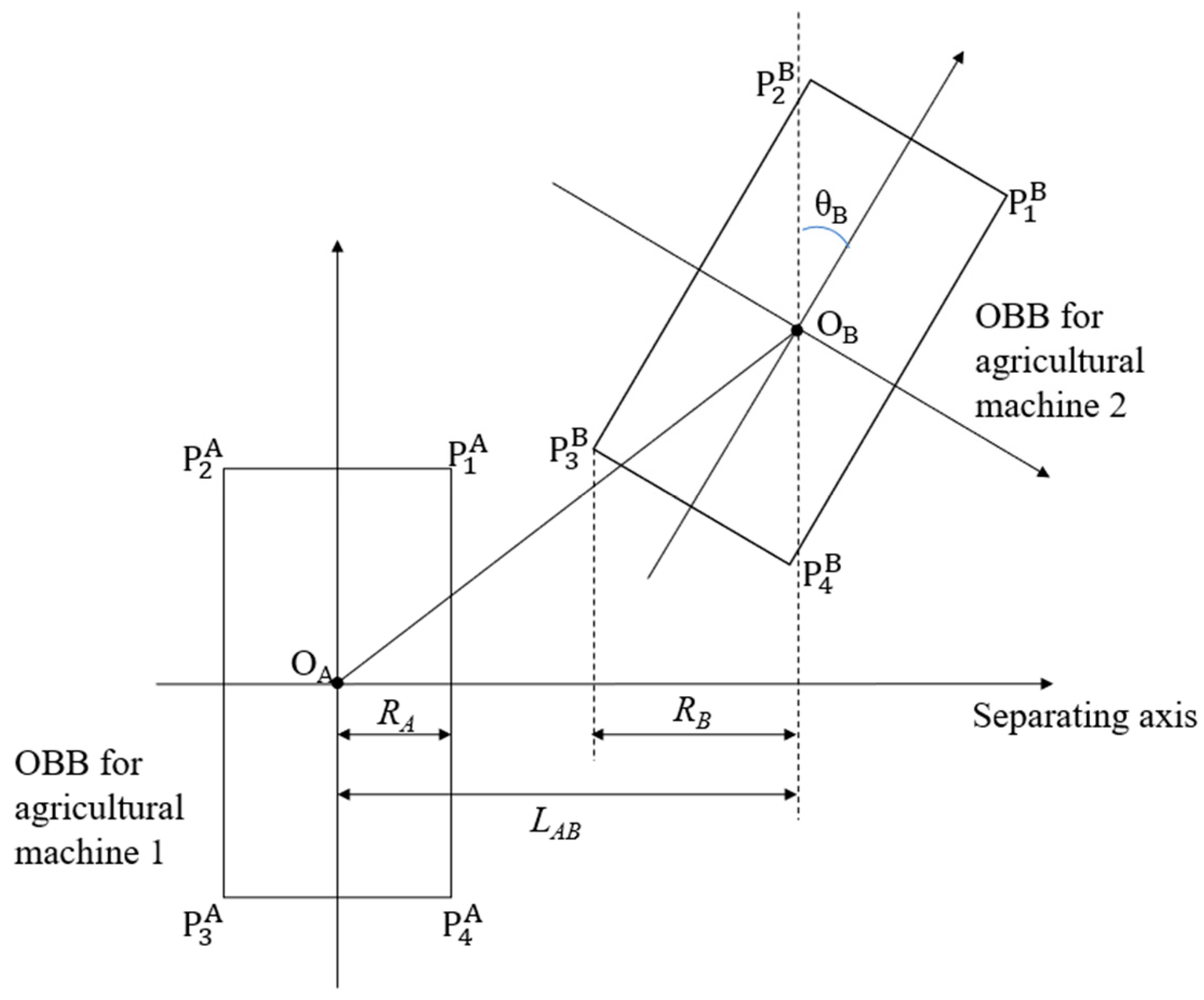
- Collision Risk Detection
- (2)
- U-turn Cooperative Steering
- (3)
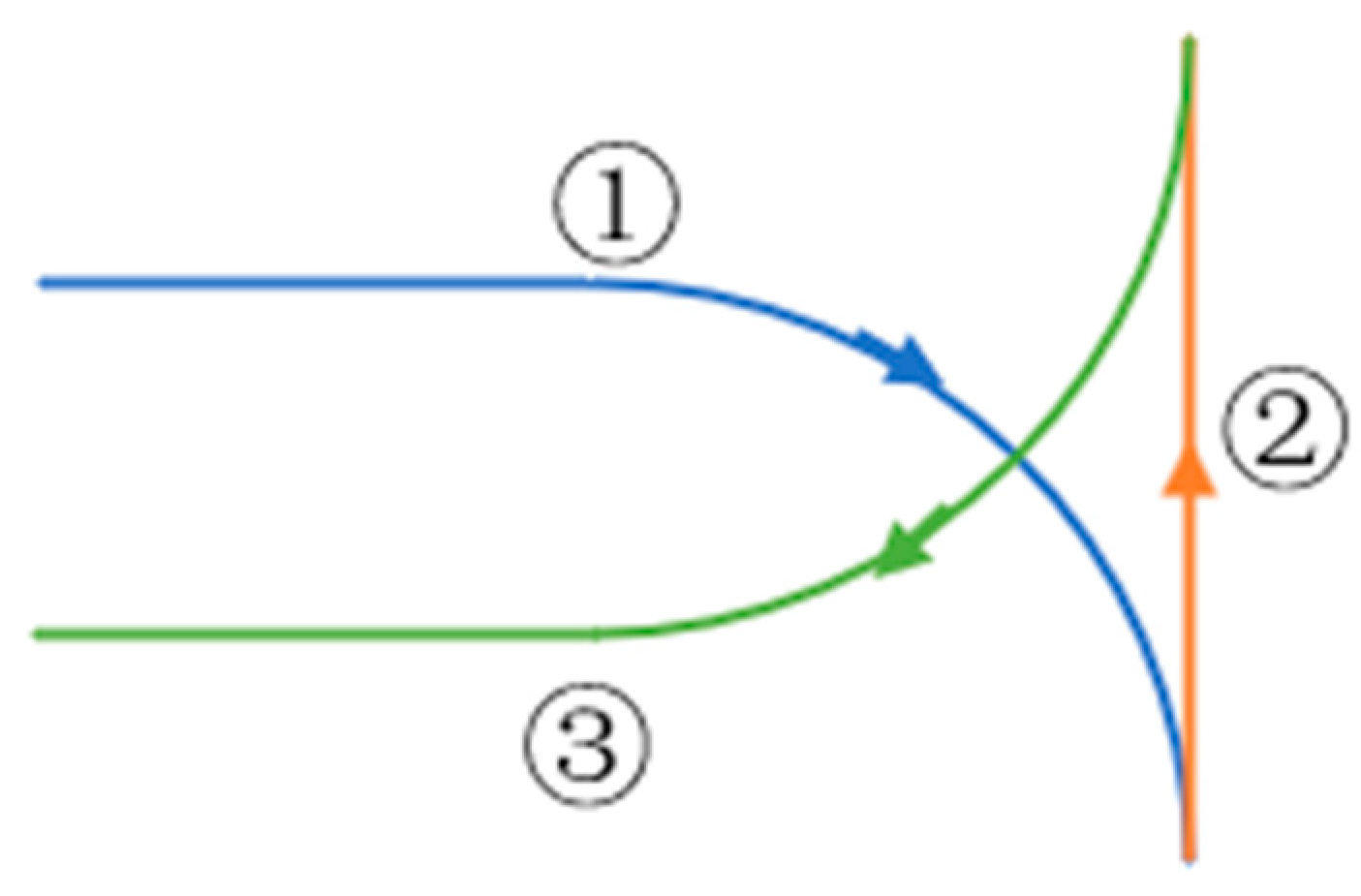
- T-turn Cooperative Steering
3.3.3. Path-Tracking Controller
- (1)
- U-turn Cooperative Steering
- (2)
- T-turn Cooperative Steering
4. Simulation Validation
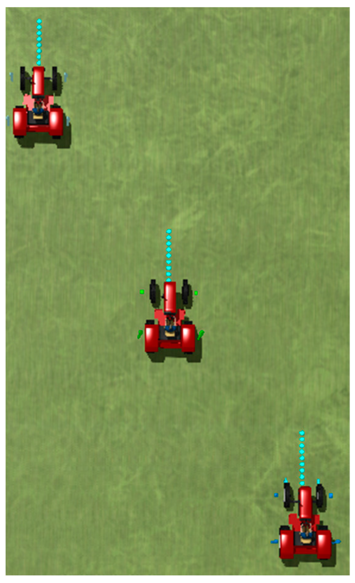
4.1. Scenario Design
4.2. Analysis of Results
4.2.1. U-Type Cooperative Steering
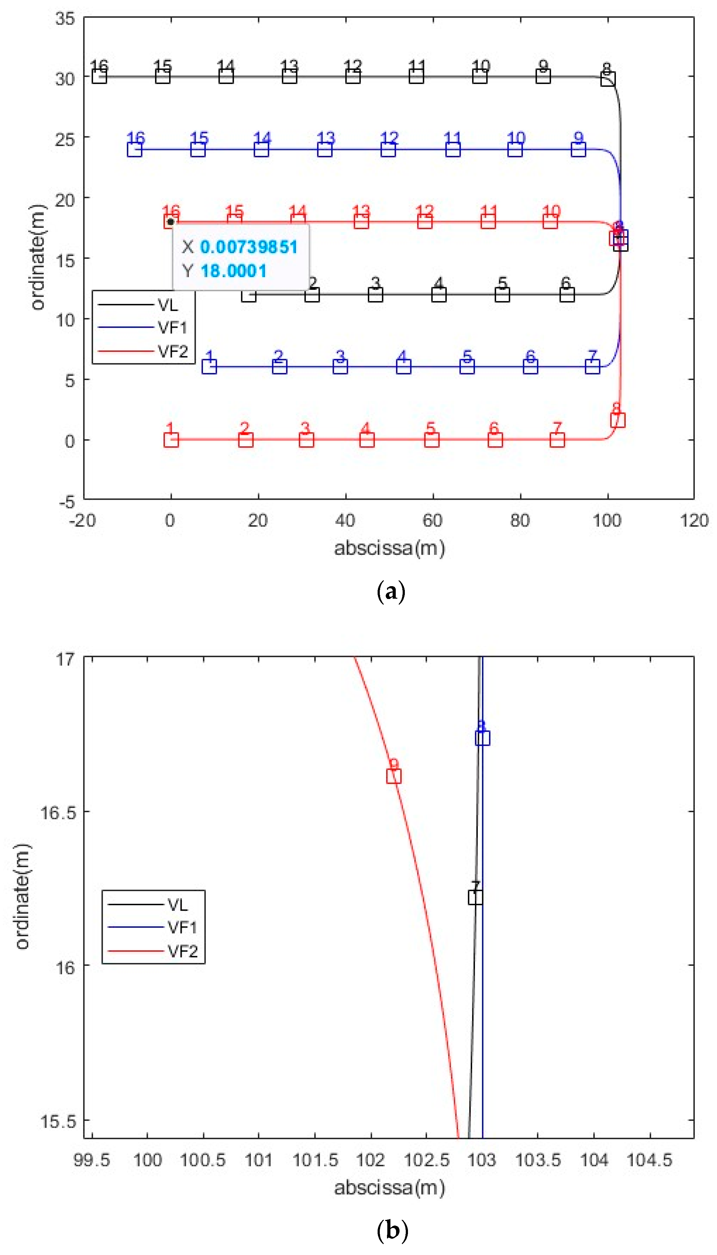
4.2.2. T-Type Cooperative Steering
5. Conclusions
Author Contributions
Funding
Data Availability Statement
Acknowledgments
Conflicts of Interest
References
- Zhang, M.; Ji, Y.; Li, S.; Cao, R.; Xu, H.; Zhang, Z. Research Progress of Agricultural Machinery Navigation Technology. Trans. Chin. Soc. Agric. Mach. 2020, 51, 1–18. [Google Scholar]
- Jin, S.; Liu, G.; Yan, X.; Shi, H.; Cheng, L. Necessity and Application Prospects of Precision Agriculture Development in China. Zhejiang Agric. Sci. 2010, 2, 414–416. [Google Scholar] [CrossRef]
- Hu, J.; Gao, L.; Bai, X.; Li, T.; Liu, X. Review of research on automatic guidance of agricultural vehicles. Trans. Chin. Soc. Agric. Eng. 2015, 31, 1–10. [Google Scholar] [CrossRef]
- Chen, X.; Wen, H.; Zhang, W.; Pan, F.; Zhao, Y. Advances and progress of agricultural machinery and sensing technology fusion. Smart Agric. 2020, 2, 1–16. [Google Scholar] [CrossRef]
- Ju, C.; Kim, J.; Seol, J.; Son, H.I. A review on multirobot systems in agriculture. Comput. Electron. Agric. 2022, 202, 107336. [Google Scholar] [CrossRef]
- Zhu, Z.; Song, Z.; Xie, B.; Chen, J.; Wutian, C.; Mao, E. Automatic Control System of Tractors Platooning. Trans. Chin. Soc. Agric. Mach. 2009, 40, 149–154. [Google Scholar]
- Rigatos, G.G. Derivative-free distributed nonlinear Kalman filtering for cooperating agricultural robots. In Proceedings of the 2013 IEEE International Symposium on Industrial Electronics, Taipei, Taiwan, 28–31 May 2013; pp. 1–6. [Google Scholar] [CrossRef]
- Li, S.; Xu, H.; Ji, Y.; Cao, R.; Zhang, M.; Li, H. Development of a following agricultural machinery automatic navigation system. Comput. Electron. Agric. 2019, 158, 335–344. [Google Scholar] [CrossRef]
- Mao, W.; Liu, H.; Hao, W.; Yang, F.; Liu, Z. Development of a Combined Orchard Harvesting Robot Navigation System. Remote Sens. 2022, 14, 675. [Google Scholar] [CrossRef]
- Martin, A.; Dionysis, B.; Claus, G.; Morten, R.; Kasper, L. In-field and inter-field path planning for agricultural transport units. Comput. Ind. Eng. 2012, 63, 1054–1061. [Google Scholar] [CrossRef]
- Conesa-Muñoz, J.; Bengochea-Guevara, J.M.; Andujar, D.; Ribeiro, A. Efficient Distribution of a Fleet of Heterogeneous Vehicles in Agriculture: A Practical Approach to Multi-path Planning. In Proceedings of the 2015 IEEE International Conference on Autonomous Robot Systems and Competitions, Vila Real, Portugal, 8–10 April 2015; pp. 56–61. [Google Scholar] [CrossRef]
- Blender, T.; Buchner, T.; Fernandez, B.; Pichlmaier, B.; Schlegel, C. Managing a Mobile Agricultural Robot Swarm for a seeding task. In Proceedings of the IECON 2016-42nd Annual Conference of the IEEE Industrial Electronics Society, Florence, Italy, 23–26 October 2016; pp. 6879–6886. [Google Scholar] [CrossRef]
- Bai, X.; Wang, Z.; Hu, J.; Gao, L.; Xiong, F. Harvester Group Corporative Navigation Method Based on Leader-Follower Structure. Trans. Chin. Soc. Agric. Mach. 2017, 48, 14–21. [Google Scholar] [CrossRef]
- Zhang, C.; Noguchi, N. Development of a multi-robot tractor system for agriculture field work. Comput. Electron. Agric. 2017, 142, 79–90. [Google Scholar] [CrossRef]
- Noguchi, N.; Will, J.; Reid, J.; Zhang, Q. Development of a master–slave robot system for farm operations. Comput. Electron. Agric. 2004, 44, 1–19. [Google Scholar] [CrossRef]
- Xu, G.; Chen, M.; Miao, H.; Yao, W.; Diao, P.; Wang, W. Control Method of Agricultural Machinery Master-Slave Following Operation Based on Model Predictive Control. Trans. Chin. Soc. Agric. Mach. 2020, 51, 11–20. [Google Scholar] [CrossRef]
- Wang, Z. Design and Realization on Autonomous Following Control System for Agricultural Vehicles. Master’s Thesis, Nanjing Agricultural University, Nanjing, China, 2014. [Google Scholar]
- Zhang, C.; Noguchi, N.; Yang, L. Leader–follower system using two robot tractors to improve work efficiency. Comput. Electron. Agric. 2016, 121, 269–281. [Google Scholar] [CrossRef]
- Stavros, G.; Vougioukas, A. distributed control framework for motion coordination of teams of autonomous agricultural vehicles. Biosyst. Eng. 2012, 113, 284–297. [Google Scholar] [CrossRef]
- Zhang, W.; Zhang, Z.; Luo, X.; He, J.; Hu, L.; Yue, B. Position-velocity coupling control method and experiments for longitudinal relative position of harvester and grain truck. Trans. Chin. Soc. Agric. Eng. 2021, 37, 1–11. [Google Scholar] [CrossRef]
- Zheng, X. Master-Slave Cooperative Control Method Harvester-Grain Carrier. Master’s Thesis, Shenyang University of Technology, Shenyang, China, 2021. [Google Scholar] [CrossRef]
- Abe, G.; Mizushima, A.; Noguchi, N. Mizushima and Noboru Noguchi. Study on a Straight Follower Control Algorithm based on a Laser Scanner. J. Jpn. Soc. Agric. Mach. 2005, 67, 65–71. [Google Scholar] [CrossRef]
- Iida, M.; Kudou, M.; Ono, K.; Umeda, M. Automatic following control for agricultural vehicle. In Proceedings of the 6th International Workshop on Advanced Motion Control. Proceedings (Cat. No.00TH8494), Nagoya, Japan, 30 March–1 April 2000; pp. 158–162. [Google Scholar] [CrossRef]
- Zhang, X.; Geimer, M.; Grandl, L.; Kammerbauer, B. Method for an electronic controlled platooning system of agricultural vehicles. In Proceedings of the 2009 IEEE International Conference on Vehicular Electronics and Safety (ICVES), Pune, India, 11–12 November 2009; pp. 156–161. [Google Scholar] [CrossRef]
- Zhai, Z.; Wang, X.; Wang, L.; Zhu, Z.; Du, Y.; Mao, E. Collaborative Path Planning for Autonomous Agricultural Machinery of Master-Slave Cooperation. Trans. Chin. Soc. Agric. Mach. 2021, 52, 542–547. [Google Scholar] [CrossRef]
- Hu, Z.; Qin, Q. Algorithm for Finding Minimum Volume Oriented Bounding Boxes Based on Convex Hull. J. Hunan Univ. Nat. Sci. 2019, 46, 105–111. [Google Scholar] [CrossRef]
- Liu, C.; Jiang, X.; Shi, H. Improved Collision Detection Algorithm Based on Oriented Bounding Box. Comput. Technol. Dev. 2018, 28, 43–48. [Google Scholar] [CrossRef]


| Parameter | Value | |
|---|---|---|
| Model | YTO-LX800 | |
| Dimensions (mm) | 4250 × 2090 × 2850 | |
| Minimum turning radius (m) | 4 | |
| Wheelbase (mm) | 2342 | |
| Total vehicle weight (kg) | 2725 | |
| Speed range (km/h) | Forward | 1.92 to 31.72 |
| Reverse | 5 to 15.01 | |
| Maximum traction force (kN) | ≥22.4 | |
Disclaimer/Publisher’s Note: The statements, opinions and data contained in all publications are solely those of the individual author(s) and contributor(s) and not of MDPI and/or the editor(s). MDPI and/or the editor(s) disclaim responsibility for any injury to people or property resulting from any ideas, methods, instructions or products referred to in the content. |
© 2024 by the authors. Licensee MDPI, Basel, Switzerland. This article is an open access article distributed under the terms and conditions of the Creative Commons Attribution (CC BY) license (https://creativecommons.org/licenses/by/4.0/).
Share and Cite
Zhu, W.; Zhang, Y.; Kong, W.; Jiang, F.; Ji, P. A Versatile Control Method for Multi-Agricultural Machine Cooperative Steering Applicable to Two Steering Modes. World Electr. Veh. J. 2024, 15, 126. https://doi.org/10.3390/wevj15040126
Zhu W, Zhang Y, Kong W, Jiang F, Ji P. A Versatile Control Method for Multi-Agricultural Machine Cooperative Steering Applicable to Two Steering Modes. World Electric Vehicle Journal. 2024; 15(4):126. https://doi.org/10.3390/wevj15040126
Chicago/Turabian StyleZhu, Weizhen, Yuhao Zhang, Weiwei Kong, Fachao Jiang, and Pengxiao Ji. 2024. "A Versatile Control Method for Multi-Agricultural Machine Cooperative Steering Applicable to Two Steering Modes" World Electric Vehicle Journal 15, no. 4: 126. https://doi.org/10.3390/wevj15040126
APA StyleZhu, W., Zhang, Y., Kong, W., Jiang, F., & Ji, P. (2024). A Versatile Control Method for Multi-Agricultural Machine Cooperative Steering Applicable to Two Steering Modes. World Electric Vehicle Journal, 15(4), 126. https://doi.org/10.3390/wevj15040126