Abstract
In response to the issues of hybrid tractors’ energy management strategies, such as reliance on experience, difficulty in achieving optimal control, and incomplete analysis of typical operating conditions of tractors, an energy management strategy based on dynamic programming is proposed in combination with various typical operating conditions of tractors. This is aimed at providing a reference for the modeling and energy management strategies of series hybrid tractors. Taking the series hybrid tractor as the research object, the tractor dynamics models under three typical working conditions of plowing, rotary tillage, and transportation were established. With the minimum total fuel consumption of the tractor as the optimization target, the engine power as the control variable, and the state of charge of the power battery as the state variable, an energy management strategy based on a dynamic programming algorithm was established and simulation experiments were conducted. The simulation results show that, compared with the power-following energy management strategy, the energy management strategy based on the dynamic programming algorithm can reasonably control the operating state of the engine. Under the three typical working conditions of plowing, rotary tillage, and transportation, the battery SOC consumption increased by approximately 8.37%, 7.24%, and 0.77%, respectively, while the total fuel consumption decreased by approximately 25.28%, 21.54%, and 13.24%, respectively.
1. Introduction
Tractors occupy an important position in the development of modern agriculture and are one of the main types of agricultural power machinery. However, traditional diesel tractors have problems such as high pollution emissions and poor fuel economy [1,2,3]. Facing increasingly strict emission standards around the world, the agricultural machinery industry is also increasingly urgent in its demand for environmentally friendly and energy-saving agricultural tractors [4,5]. Pure electric tractors can achieve zero pollution, but, due to current battery technology limitations, they have a short continuous operation time and are unable to perform high-load agricultural production for extended periods of time [6,7]. The series hybrid tractor is equipped with an engine and a generator on the basis of the pure electric tractor. By reasonably controlling the operating state of the engine, it can achieve the same power performance as the traditional diesel tractor while reducing fuel consumption [8,9,10].
The energy management strategy has an important impact on the fuel economy, power performance, and lifespan of the power source of the hybrid tractor [11,12]. Currently, energy management strategies are basically divided into three categories: rule-based energy management strategies, learning-based energy management strategies, and optimization-based energy management strategies [13]. Rule-based energy management strategies are simple to develop and highly feasible, and were the first energy management strategies applied to hybrid vehicles [14]. Chen et al. [15] designed an adaptive fuzzy energy management strategy for extended-range electric vehicles by using BP neural network optimized by an improved genetic algorithm, which effectively improved the fuel economy of the whole vehicle. Yang et al. [16] designed an energy management strategy that combines constant temperature control, power following, and fuzzy rules. This strategy reduces equivalent hydrogen consumption while increasing the lifespan of the system. Zou et al. [17] proposed an energy management strategy for fuel cell hybrid vehicles that utilizes fuzzy logic to optimize the power following control strategy. This control strategy optimizes the output power of the hydrogen fuel cell while reducing hydrogen consumption. However, rule-based energy management strategies usually require a great deal of debugging to determine suitable parameters, relying on the developer’s design experience, and it is difficult to achieve optimal control [18].
Learning-based energy management strategies are control strategies with adaptive learning capabilities and good robustness [19]. Xu et al. [20] proposed a supervised learning-based driving cycle pattern recognition method that can accurately predict road conditions and improve the fuel economy of hybrid vehicles. Wu et al. [21] proposed an energy management strategy based on deep deterministic policy gradients, which has near-global optimal dynamic programming performance and can achieve optimal energy allocation for vehicles in continuous spaces. Wang et al. [22] combined computer vision with deep reinforcement learning, enabling the algorithm to autonomously learn the optimal control strategy using visual information collected from on-board cameras, which resulted in reduced fuel consumption and achieved performance at 96.5% of the global optimum dynamic programming. However, learning-based energy management strategies require a large amount of data for training, have high computational requirements, and have relatively complex control strategies [23].
Optimization-based energy management strategies use cost functions as optimization objectives and measure the optimization effect by minimizing the cost function [24]. Zhao et al. [25] proposed an energy management strategy based on the principle of maximizing external energy efficiency, which significantly reduces equivalent hydrogen consumption and improves the overall efficiency of the hybrid tractor. Dou et al. [26] proposed an energy management strategy based on an equivalent fuel consumption minimization algorithm. This strategy can adaptively distribute the required torque based on the load condition, resulting in better fuel consumption compared to rule-based energy management strategies. Curiel-Olivares et al. [27] proposed a model-predictive-based energy management strategy for series hybrid tractors. This strategy outperforms rule-based energy management strategies in terms of fuel consumption while also optimizing the operating state of the battery.
This article takes a series diesel–electric hybrid tractor as the research object and proposes a globally optimal hybrid energy management strategy based on dynamic programming (DP) [28,29,30]. By reasonably controlling the operating state of the engine and optimizing its output power, it is possible to reduce the total fuel consumption of tractors under three typical working conditions of plowing, tilling, and transportation while ensuring the tractor’s power performance. The remainder of this article is organized as follows. Section 2 introduces the topological structure and main performance parameters of the power system for series hybrid tractors. Section 3 explains the simulation models of various components of series hybrid tractors. Section 4 designs two energy management strategies, namely those based on dynamic programming and power following (PF). Section 5 verifies and analyzes the energy management strategies through simulation experiments. Section 6 discusses the results of the simulation experiments and outlines future research directions. Section 7 summarizes the research content and experimental results of this paper.
2. Structural Parameters of Tractor’s Power System
Figure 1 shows the topological structure of the power system of a series diesel–electric hybrid tractor. This tractor uses a drive motor as the power source, and the torque output by the drive motor is transmitted to the drive wheels and power takeoff (PTO) through the transmission system. The power battery delivers power to the drive motor through a power converter. When the power battery’s charge is insufficient, the engine drives the generator to generate electricity, which is then delivered to the power battery through the power converter to charge the battery. The main component parameters of the series diesel–electric hybrid tractor are shown in Table 1, including the rated power and rated speed of the diesel engine and the drive motor, as well as the rated capacity and rated voltage of the power battery and other specification parameters.
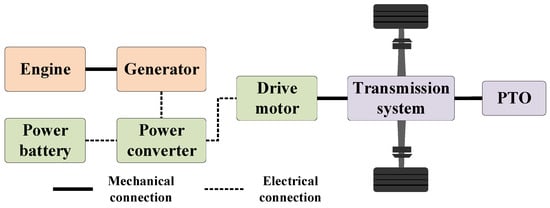
Figure 1.
Topological structure diagram of the power system for a series hybrid tractor.

Table 1.
Parameters of main components of hybrid tractor.
3. Hybrid Tractor Model Construction
3.1. Driver Model
Based on the principle of forward modeling, this article uses the difference between the target vehicle speed and the current vehicle speed as input, and the acceleration pedal opening and the brake pedal opening as output to build a driver model based on PI control. The principle of the driver model is shown in the following equation [31]:
where kp is the proportional coefficient, ki is the integral coefficient; e is the difference between the target velocity of the tractor and the current velocity of the tractor, km/h; Op is the pedal opening, where Op ∈ (0,1) indicates the accelerator pedal opening, and Op ∈ (−1,0) indicates the brake pedal opening; vref is the target velocity of the tractor, km/h, and vact is the current velocity of the tractor, km/h.
3.2. Generator Set Model
In the structure of a series hybrid system, the engine drives the generator to generate electricity through mechanical connection, and the engine and generator are not connected to the transmission system, relatively independent of the power system of the entire vehicle. Therefore, the engine and generator are usually considered as a whole, namely the generator set. The research on hybrid energy management strategies focuses on analyzing the fuel economy of tractors, so numerical modeling methods are adopted, considering only the input and output relationships of the generator set, as shown in the following equation [32]:
where Pe is the engine power, kW; ne is the engine speed, r/min; Te is the engine torque, N·m; PG is the generator set power, kW; ηG is the generator efficiency.
Under the entire set of operating conditions, the total fuel consumption of the engine is represented by the following equation:
where E is the total fuel consumption of the engine, L; be is the fuel consumption rate of the engine, g/kWh; and ρf is the density of diesel fuel, g/L.
In order to achieve optimal fuel economy for the engine, the engine MAP and optimal operating line (OOL) were fitted using engine bench test data, as shown in Figure 2.
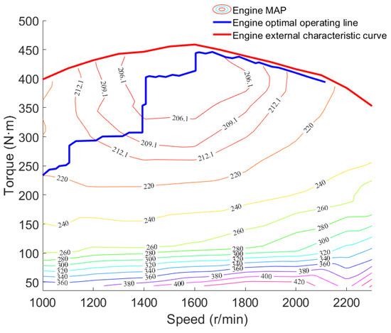
Figure 2.
Diesel engine MAP.
Figure 2 includes the engine fuel consumption rate MAP, optimal operating line of the engine, and the external characteristic curve of the engine. The fitted engine characteristic curve in Figure 2 can provide data support for the engine to operate in the optimal state and accurately obtain the current fuel consumption rate of the engine.
3.3. Drive Motor Model
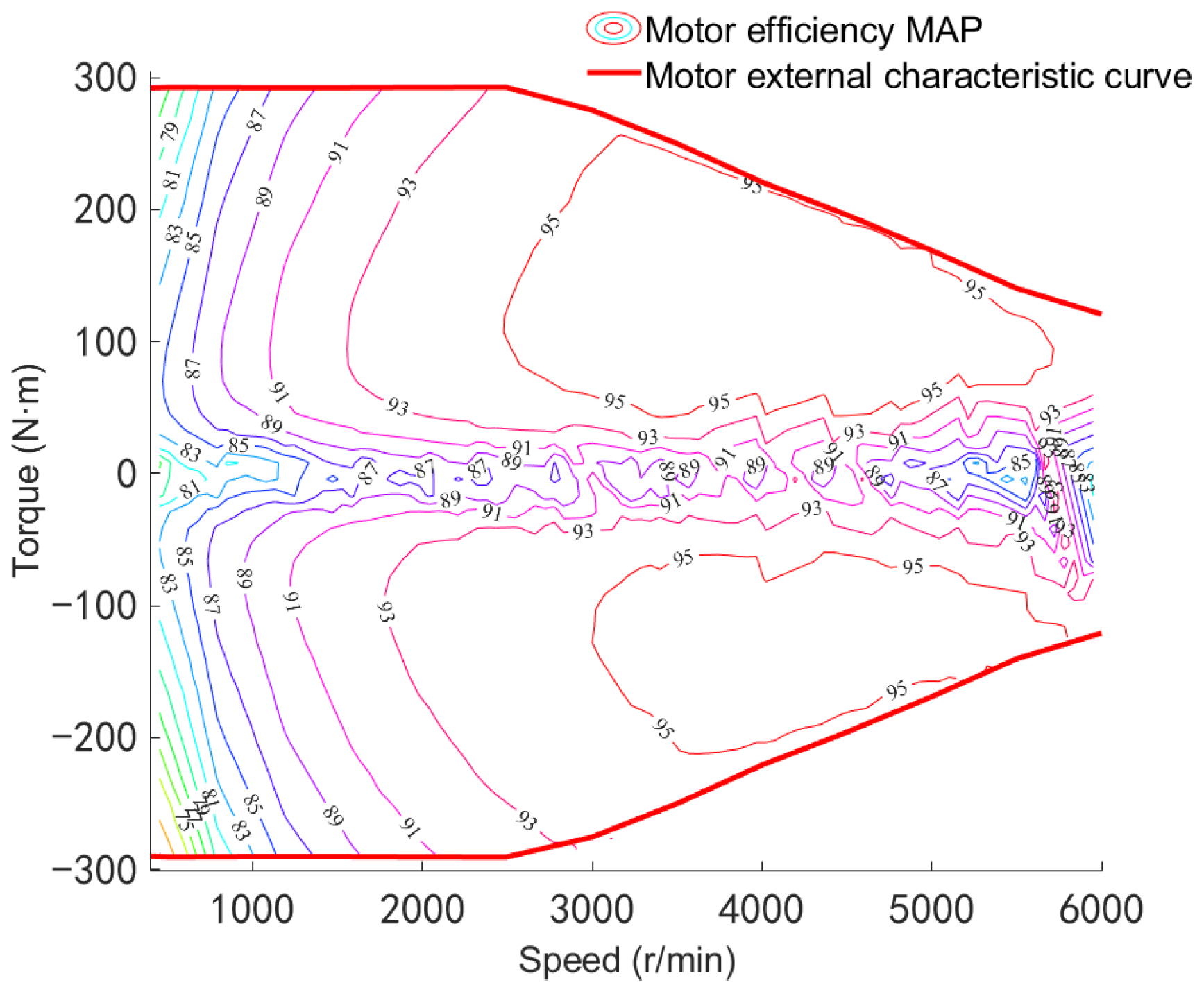
The drive motor model employs a numerical modeling approach. The corresponding relationship between motor speed and motor torque is determined through drive motor bench test data using a look-up table method. The torque control mode is adopted, and the motor output is controlled through the accelerator pedal opening signal. The mathematical modeling principle of the drive motor is shown in Equation (7). Based on the drive motor bench test data, the drive motor’s external characteristic curve is obtained, and then the motor efficiency MAP is obtained through interpolation fitting, as shown in Figure 3 [33]:
where nm is the drive motor speed, r/min; Tm is the drive motor torque, N·m; Tm_max is the maximum torque at the current drive motor speed; kac is the accelerator pedal opening; ηm is the drive motor efficiency; and Pm is the drive motor power, kW.
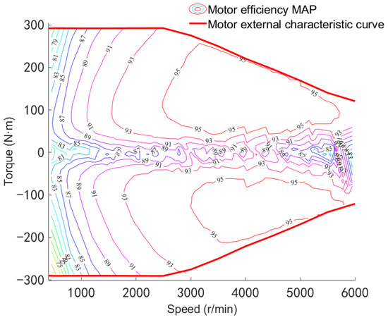
Figure 3.
Motor efficiency MAP.
3.4. Transmission System Model
The power source of a series hybrid tractor comes from the drive motor, and the torque generated by the drive motor acts on the drive wheels and the PTO through the transmission system. The transmission system model is shown in the following equation:
where Ftr is the forward traction force acting on the tractor through the transmission system by the drive motor torque, N; ig is the gear ratio of the transmission; i0 is the gear ratio of the final drive; ηT is the efficiency of the transmission system; Rw is the radius of the drive wheel, m; Fbr is the braking force of the brake, N; kbr is the brake pedal opening; Fbr_max is the maximum braking force of the brake, N.
The drive motor speed can also be calculated based on the tractor’s current vehicle speed and transmission system parameters, as shown in Equation (10):
3.5. Tractor Plowing Condition Dynamics Model
Under the plowing condition of a tractor, its driving resistance is mainly determined by the plowing resistance and the rolling resistance, which are calculated as shown in the following equation:
where Ft is the driving force, N; FL is the plowing resistance, N; Ff is the rolling resistance, N; Z is the number of plowshares; b is the width of a single plowshare, cm; h is the plowing depth, cm; k is the specific resistance of the soil, N/cm2; m is the operating mass of the tractor, kg; g is the acceleration of gravity, m/s2; f is the rolling resistance coefficient; α is the slope angle, (ο).
The current vehicle speed of the tractor can also be calculated based on the driving force, as shown in Equation (14):
3.6. Tractor Rotary Tillage Condition Dynamics Model
When performing rotary tillage operations, the series hybrid tractor can neglect the effects of air resistance and acceleration resistance. Due to the complexity of the formula for calculating rotary tillage power and the many influencing factors, this paper uses empirical formulas for calculation. The power balance is shown in the following equation [34,35]:
where Pdrive is the tractor’s driving power, kW; Fi is the slope resistance, N; Pr is the power of the rotary tiller, kW; B is the width of the rotary tillage area; ηr is the transmission efficiency of the rotary tiller unit.
3.7. Tractor Transportation Condition Dynamics Model
When a tractor is performing transportation operations, the relationship between the driving force and the driving resistance is balanced as shown in the following equation:
where Fac is the acceleration resistance, N; Faf is the air resistance, N; δ is the tractor mass conversion coefficient; a is the tractor acceleration, m/s2; CD is the wind resistance coefficient of the tractor; A is the windward area of the tractor, m2.
3.8. Power Battery Model
In the research on energy management strategies for hybrid electric vehicles, the battery model mainly reflects the interrelationship between the battery power and the power of other power systems in the vehicle. Therefore, this article treats the power battery as an ideal voltage source, ignores the temperature’s impact on the battery’s voltage, and adopts the Rint model to model the power battery. The dynamic equations for the battery’s state of charge (SOC) and battery power are shown in the following equation:
where Uoc is the open-circuit voltage of the power battery, V; Rint is the internal resistance of the power battery, Ω; PB is the battery power, kW; QB is the rated capacity of the battery, A·h; ηB is the charge and discharge efficiency of the power battery. When (Pm + Pe) is less than 0, the power battery is charging; when (Pm + Pe) is greater than 0, the power battery is discharging.
3.9. Tractor Simulation Model
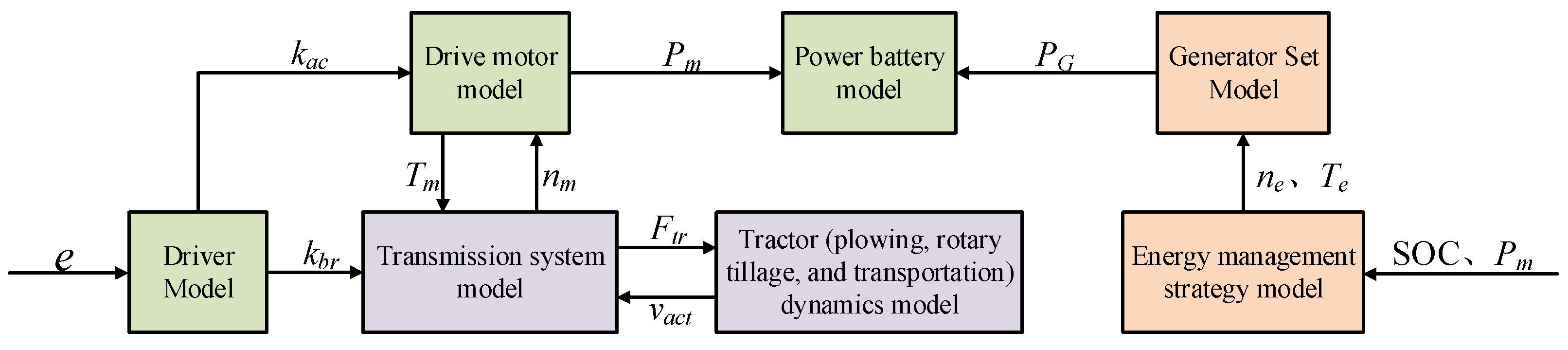
By studying the working characteristics and structural composition of a series hybrid tractor and combining the modeling requirements of the energy management strategy, a tractor simulation model is built based on Matlab/Simulink. The model includes a driver model, a drive motor model, a transmission system model, a power battery model, tractor (plowing, rotary tillage, and transportation) dynamics models, a generator set model, and an energy management strategy model. The specific model structure is shown in Figure 4. Based on the difference e between the target vehicle speed and the current vehicle speed under the current operating conditions, the driver model outputs the acceleration pedal angle and brake pedal angle (kac, kbr). By controlling the transmission system model, the dynamic model of the tractor under various operating conditions, and the drive motor model through the acceleration pedal angle and brake pedal angle, the drive motor power Pm is obtained. Meanwhile, the power PG of the generator set model is allocated according to the established control strategy through the energy management strategy model. Finally, the battery power PB and SOC are calculated through the power battery model.
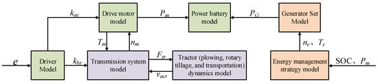
Figure 4.
Simplified diagram of tractor simulation model.
4. Energy Management Strategy Design
4.1. Energy Management Strategy Based on Dynamic Programming
4.1.1. Dynamic Programming Energy Management Strategy Model
For a series hybrid tractor, the optimization goal of its energy management strategy is to reasonably control the operating state and output power of the engine so that the tractor achieves the optimal fuel consumption under the current working conditions. The DP algorithm is a multi-stage decision optimization algorithm that divides the multi-stage decisionmaking process into multiple single-stage problems based on the Bellman optimality principle. By defining appropriate control variables, state variables, and objective functions, the DP algorithm uses reverse calculation to solve the multiple single-stage problems to obtain the optimal control.
During the entire set of operating conditions of a tractor, its overall state changes over time. Therefore, when establishing a dynamic programming algorithm, the entire set of operating conditions is divided into N stages with a 1 s interval based on the tractor’s operating conditions. State variables reflect the change process of the controlled object. For a series hybrid tractor, the state of charge (SOC) of the power battery can represent the state changes of the tractor under the entire set of operating conditions. Therefore, the SOC of the power battery is selected as the state variable. During the operation of the tractor, the main factor affecting the change in the SOC of the power battery is the output power of the engine. Therefore, the engine power is selected as the control variable.
The state variables and control variables are discretized as shown in Equation (24):
where N is the dimensions of the discrete space; j is the number of discrete points.
From Equation (22), the state transition equation can be obtained as
Taking the total fuel consumption of the engine under the entire set of operating conditions as the optimization objective, the optimization objective function can be obtained from Equation (6) as
To ensure that all components of the tractor operate within a reasonable range, the following constraints are added:
where SOCmin and SOCmax are the minimum and maximum allowable values for the SOC of the power battery; PB_min and PB_max are the minimum and maximum power of the power battery during operation; Pe_min, Pe_max, ne_min, ne_max, Te_min, and Te_max are the minimum and maximum power, minimum and maximum speed, and minimum and maximum torque of the engine during operation, respectively.
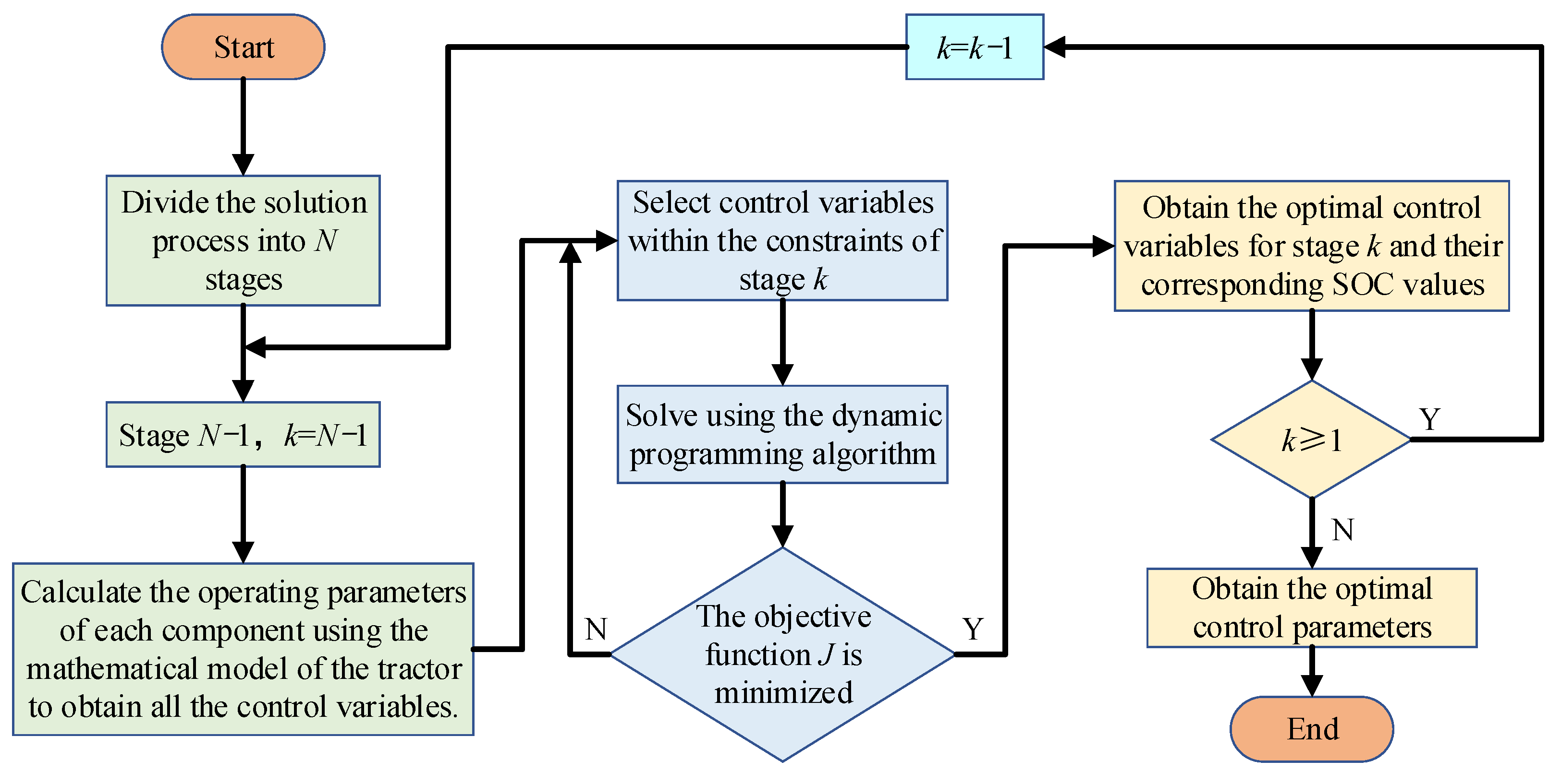
4.1.2. The Solution Process of Dynamic Programming Algorithm
The energy management strategy based on dynamic programming optimizes the operating state and output power of the engine throughout the entire set of working conditions using the dynamic programming algorithm, aiming to achieve the best fuel economy for the tractor. The solution process of dynamic programming is shown in Figure 5.
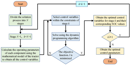
Figure 5.
The solution process of dynamic programming.
The specific steps are as follows:
- The solution process is divided into N stages based on the operating conditions. The operational parameters of each component of the tractor at each stage are calculated using the tractor’s mathematical model, and all control variables are solved. To further optimize the fuel consumption of the tractor, all control variables, including the calculated engine power Pe, corresponding engine speed ne, and engine torque Te, are selected from the OOL fitted in Figure 2.
- Select control variables that satisfy the constraints of the current stage and use dynamic programming to solve for the state variables and control variable parameter values that yield the minimum value of the objective function J for that stage.
- Let N = N − 1, which enters the next stage of the solution operation. This process continues until k = 0, at which point the optimal control variables and corresponding SOC dataset are obtained, and the solution process is complete.
4.2. Energy Management Strategy Based on Power Following
The power following-based energy management strategy is a rule-based control strategy. In a series hybrid tractor, this strategy uses the demand power of the drive motor and the remaining battery charge of the power battery to determine the start–stop and output power of the engine. The principle of this strategy is shown in Figure 6.
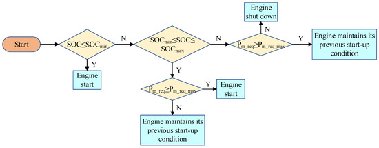
Figure 6.
Power following schematic diagram.
Where Pm_req is the required power of the drive motor; Pm_req_max is the maximum required power of the drive motor.
The specific steps are as follows:
- When SOC ≤ SOCmin, the engine starts.
- When SOCmin ≤ SOC ≤ SOCmax, if Pm_req ≥ Pm_req_max, the engine starts; otherwise, the engine maintains the started state from the previous moment.
- When SOC ≥ SOCmax, if Pm_req ≥ Pm_req_max, the engine maintains the started state from the previous moment; otherwise, the engine shuts down.
To better compare the two control strategies, the engine control parameters output by the power following-based energy management strategy will also be selected from the OOL fitted in Figure 2.
5. Simulation and Results Analysis
5.1. Plowing Condition
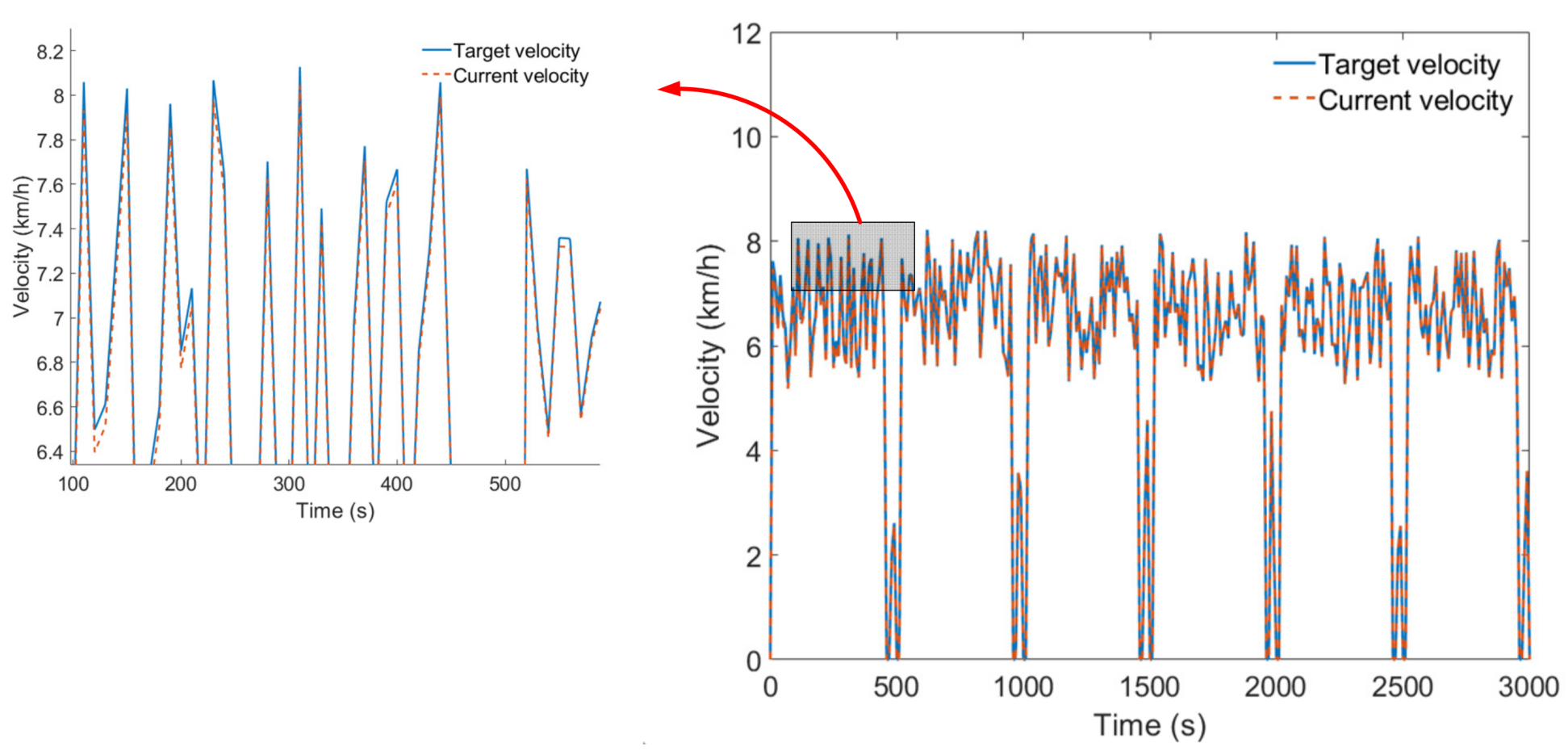
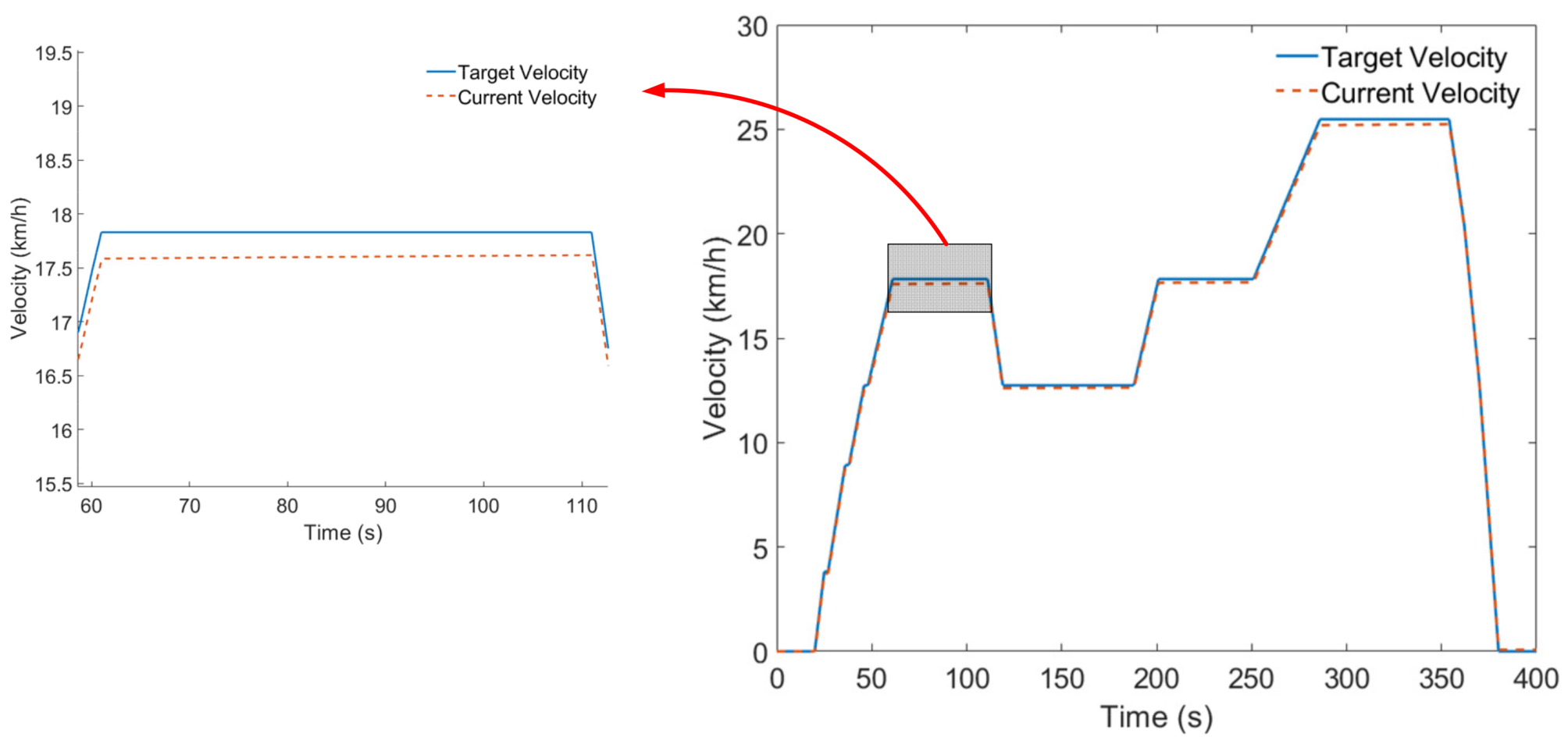
As shown in Figure 7, the target vehicle speed tracking effect of the simulation model under the plowing condition is demonstrated. The results indicate that, under the plowing condition, the simulation model can effectively track the target vehicle speed with a maximum error of no more than 0.24 km/h, meeting the test requirements.
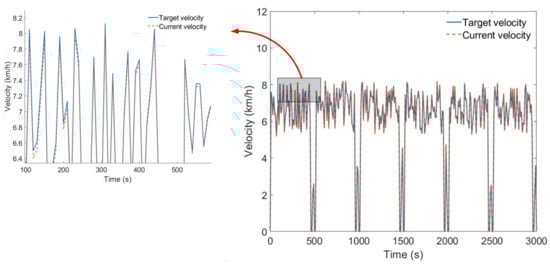
Figure 7.
Vehicle speed tracking effect under plowing condition.
When the tractor performs plowing operations, the changes in drive motor power and battery power under two energy management strategies are shown in Figure 8. As can be observed from Figure 8a, under the plowing condition, the peak power of the drive motor is approximately 49.66 kW. As can be observed from Figure 8b, under the energy management strategy based on power following, the battery power will have negative values as the load of the plowing condition increases, indicating that the generator set will be activated to charge the battery during each plowing cycle. Under the energy management strategy based on dynamic programming, the battery power remains positive for approximately the first 2118 s. After approximately 2118 s, the battery power begins to decrease, at which point the generator set starts to operate and charge the battery. During the periods from approximately 2471 s to 2499 s and from 2971 s to 2999 s, the battery exhibits negative power, indicating that the entire tractor’s load power is being supplied by the generator set.
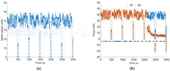
Figure 8.
(a) Drive motor power; (b) battery power.
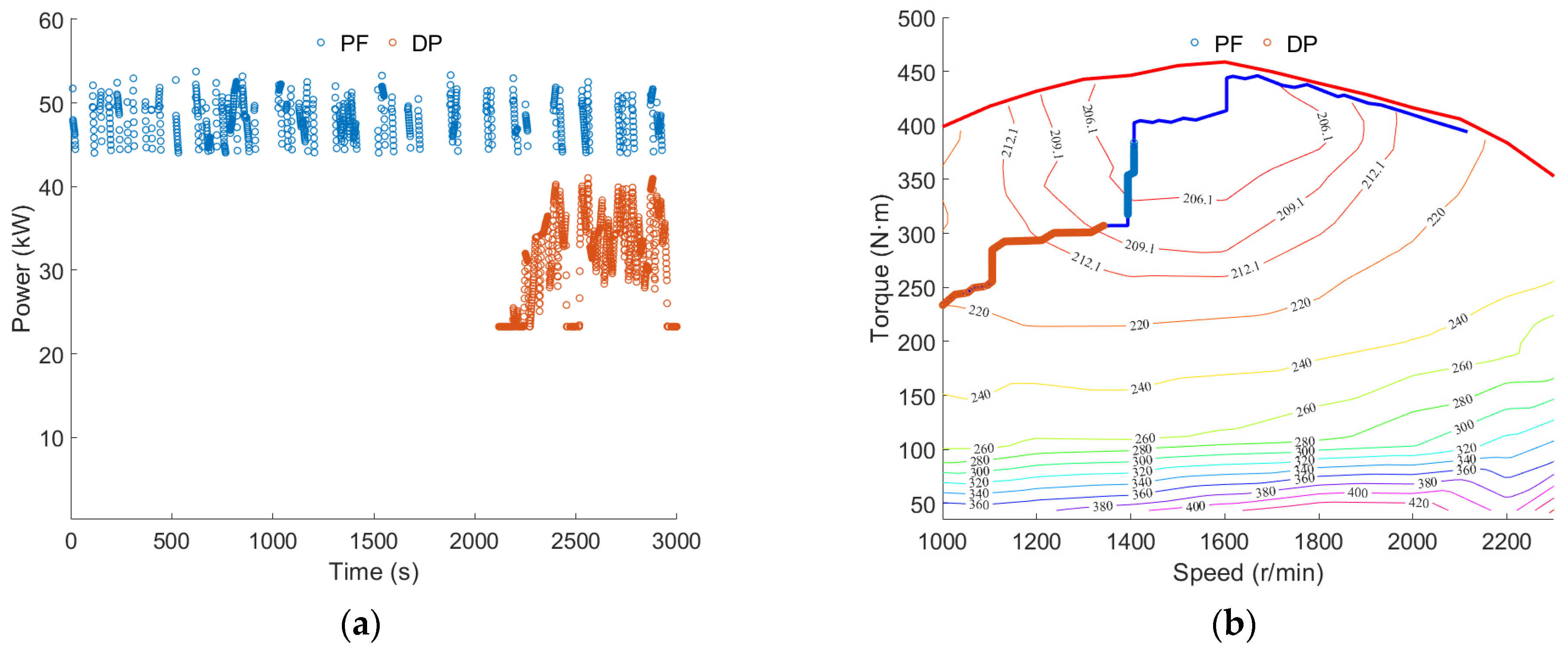
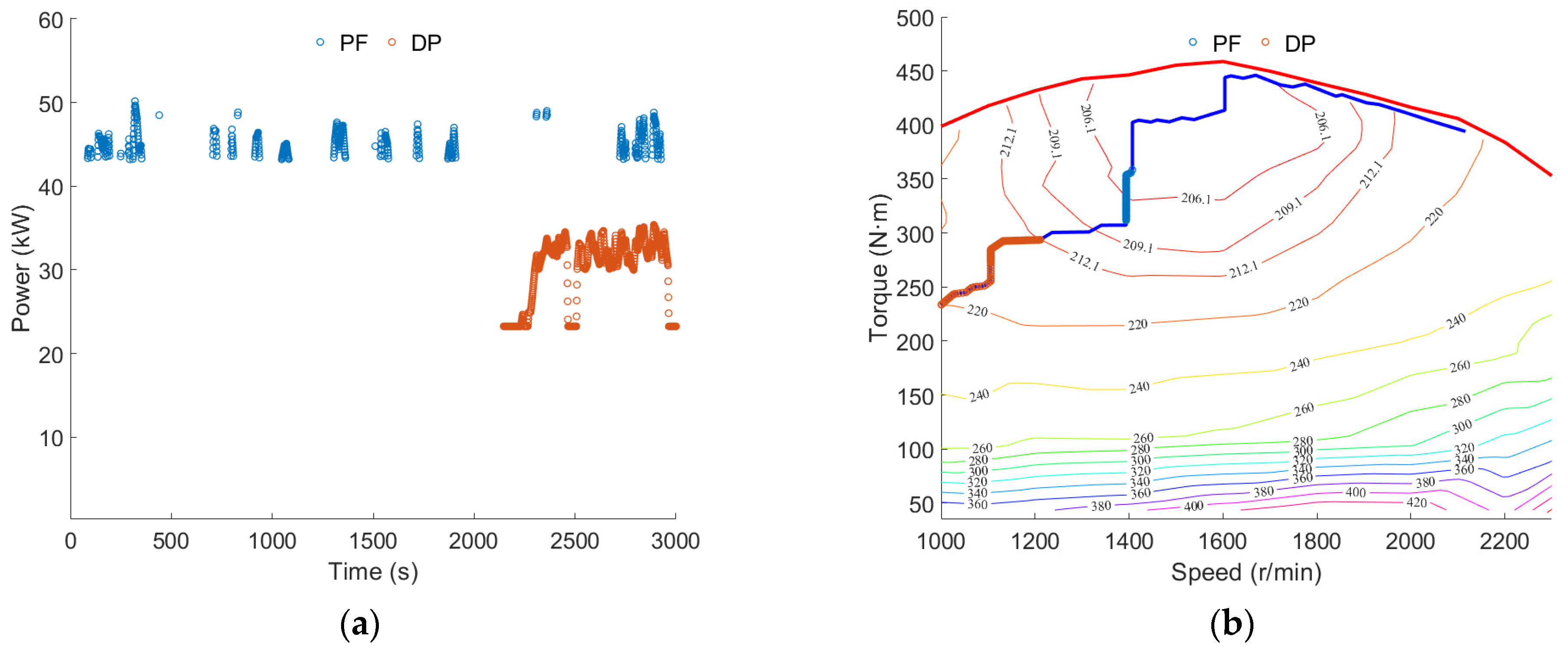
The operating state of the engine under the plowing condition is shown in Figure 9. As can be observed from Figure 9a, under the energy management strategy based on power following, the engine starts and stops multiple times throughout the entire plowing condition, with relatively short continuous operating times, and the peak power of the generator set is approximately 53.76 kW. On the other hand, under the energy management strategy based on dynamic programming, the engine starts to operate around 2118 s, and it does not frequently start and stop, with relatively concentrated operating times and a peak power of approximately 41.03 kW. As shown in Figure 9b, under both energy management strategies, the engine operates along the optimal operating curve, but, under the energy management strategy based on dynamic programming, the engine operates within a wider range.
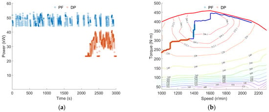
Figure 9.
(a) Engine power; (b) engine operating point.
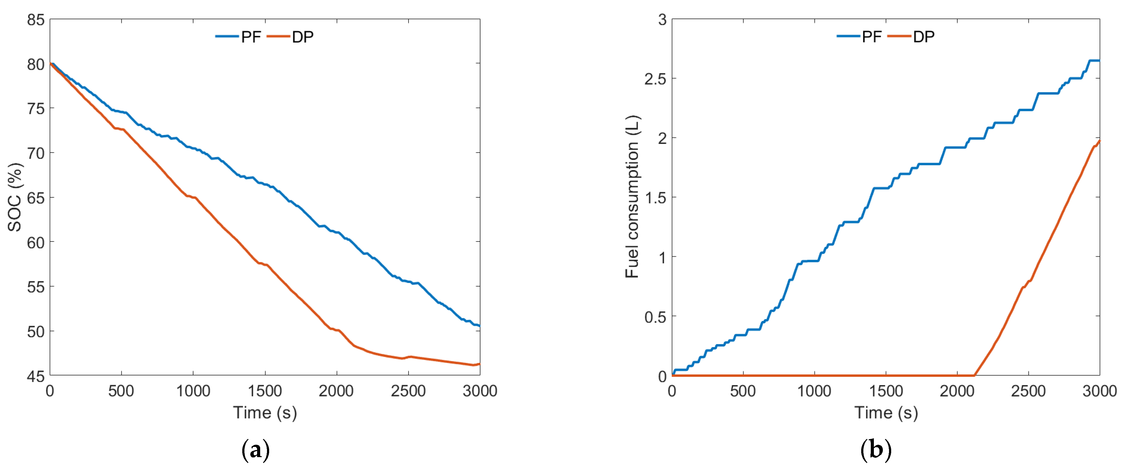
As can be observed from Figure 10a, the final SOC under the energy management strategy based on power following is approximately 50.54%, while the final SOC under the energy management strategy based on dynamic programming is approximately 46.31%. Compared to the energy management strategy based on power following, the battery SOC consumed approximately 8.37% more under the energy management strategy based on dynamic programming.
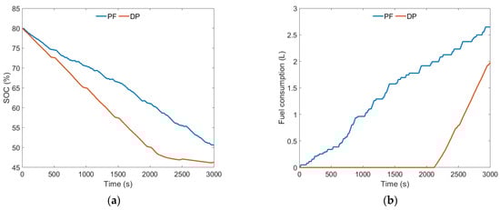
Figure 10.
(a) SOC change curve; (b) fuel consumption change curve.
As shown in Figure 10b, the total fuel consumption under the energy management strategy based on power following is 2.65 L, while the total fuel consumption under the energy management strategy based on dynamic programming is 1.98 L. With the energy management strategy based on dynamic programming, the total fuel consumption is reduced by approximately 25.28%.
5.2. Rotary Tillage Condition
As shown in Figure 11, the target vehicle speed tracking effect of the simulation model under the rotary tillage condition is demonstrated. The results indicate that, under the rotary tillage condition, the simulation model can effectively track the target vehicle speed with a maximum error of no more than 0.22 km/h, meeting the test requirements.
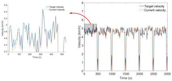
Figure 11.
Vehicle speed tracking effect under rotary tillage condition.
When the tractor performs rotary tillage operations, the changes in drive motor power and battery power under two energy management strategies are shown in Figure 12. As can be observed from Figure 12a, under the rotary tillage condition, the peak power of the drive motor is approximately 46.10 kW. As can be observed from Figure 12b, under the energy management strategy based on power following, the trend regarding battery power changes is basically consistent with that of the plowing condition. In each rotary tillage cycle, the battery exhibits negative power, causing the generator set to start and charge the battery. Under the energy management strategy based on dynamic programming, the battery power remains positive for approximately the first 2145 s. After approximately 2145 s, the battery power begins to decrease, at which point the generator set starts to operate and charge the battery. During the periods from approximately 2464 s to 2506 s and from 2963 s to 3000 s, the battery exhibits negative power, indicating that the entire tractor’s load power is being supplied by the generator set.
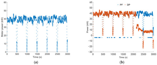
Figure 12.
(a) Drive motor power; (b) battery power.
The operating state of the engine under the rotary tillage condition is shown in Figure 13. As can be observed from Figure 13a, under the energy management strategy based on power following, the number of starts and stops of the engine during the entire rotary tillage condition has decreased compared to the plowing condition, but they remain relatively frequent, with short continuous operating times, and the peak power of the generator set is approximately 50.17 kW. On the other hand, under the energy management strategy based on dynamic programming, the engine starts to operate around 2145 s and continues to operate until the end of the rotary tillage operation, with relatively concentrated operating times and a peak power of approximately 35.39 kW. As shown in Figure 13b, under both energy management strategies, the engine operates along the optimal operating curve. However, under the energy management strategy based on dynamic programming, the engine operates within a wider range.
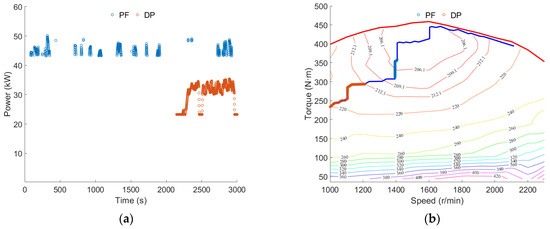
Figure 13.
(a) Engine power; (b) engine operating point.
As shown in Figure 14a, the final SOC under the power-following energy management strategy is approximately 48.76%, while the final SOC under the dynamic programming-based energy management strategy is approximately 45.23%. Compared to the power-following energy management strategy, the battery SOC consumed approximately 7.24% more under the dynamic programming-based energy management strategy.
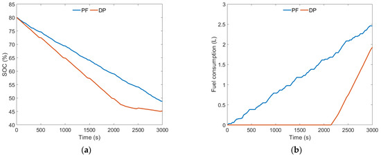
Figure 14.
(a) SOC change curve; (b) fuel consumption change curve.
As shown in Figure 14b, the total fuel consumption under the energy management strategy based on power following is 2.46 L, while the total fuel consumption under the energy management strategy based on dynamic programming is 1.93 L. With the energy management strategy based on dynamic programming, the total fuel consumption is reduced by approximately 21.54%.
5.3. Transportation Condition
The tractor transportation condition refers to the EUDC_Man driving cycle, and, based on the tractor powertrain system parameters, the maximum vehicle speed has been adjusted to 25.5 km/h. As shown in Figure 15, the target vehicle speed tracking effect of the simulation model under the transportation condition is demonstrated. The results indicate that, under the transportation condition, the simulation model can effectively track the target vehicle speed with a maximum error of no more than 0.27 km/h, meeting the test requirements.
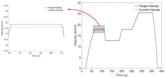
Figure 15.
Vehicle speed tracking effect under transportation condition.
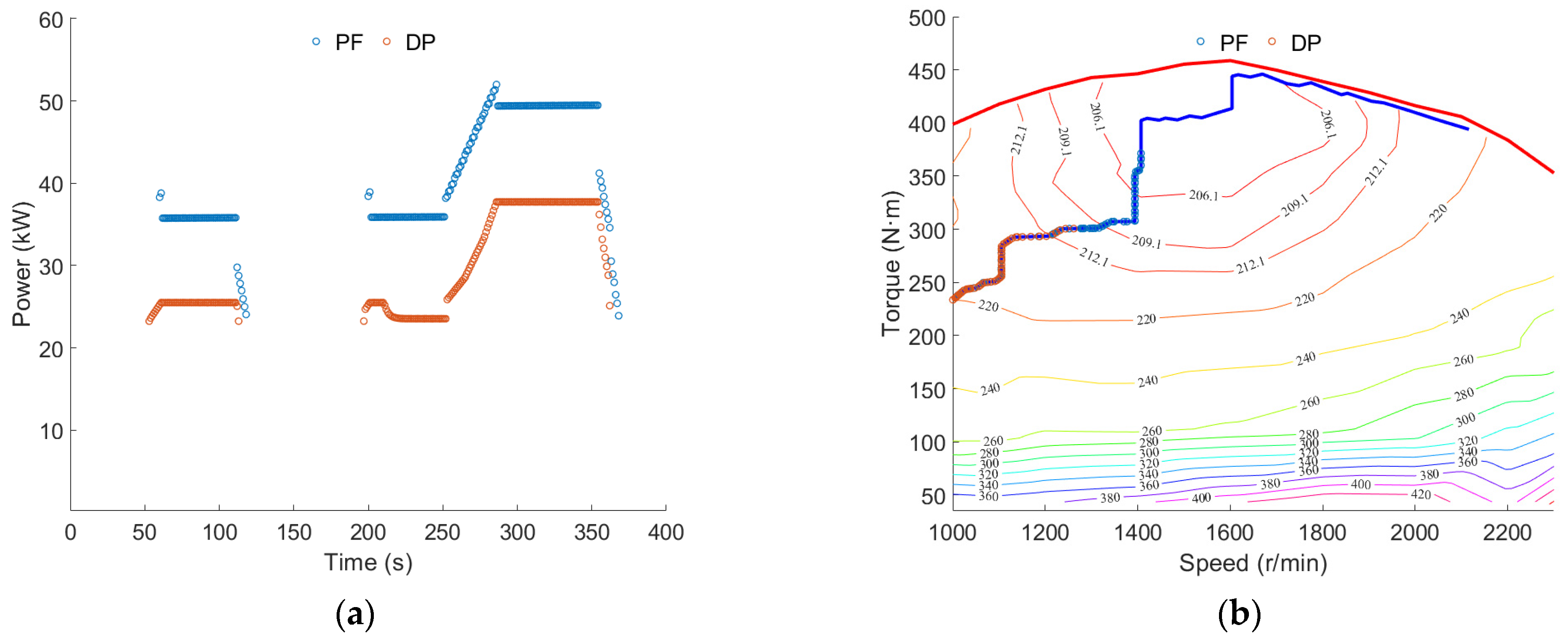
During the transportation operation of the tractor, the changes in the drive motor power and battery power under the two energy management strategies are shown in Figure 16. As can be observed from Figure 16a, under the transportation condition, the peak power of the drive motor is approximately 112.40 kW. As shown in Figure 16b, the trends in battery power changes are basically consistent under both the power-following energy management strategy and the dynamic programming-based energy management strategy, and no negative battery power occurs. Under the power-following energy management strategy, the generator set operates and the battery power decreases during approximately 60 s to 118 s and 200 s to 368 s. Under the dynamic programming-based energy management strategy, the generator set operates and the battery power decreases during approximately 53 s to 113 s and 197 s to 362 s.
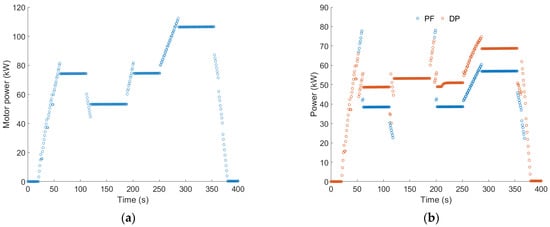
Figure 16.
(a) Drive motor power; (b) battery power.
The operating state of the engine under transportation conditions is shown in Figure 17. As can be observed from Figure 17a, under both the power-following energy management strategy and the dynamic programming-based energy management strategy, the number of starts and stops of the engine during the entire transportation condition is the same. Under the power-following energy management strategy, the peak power of the generator set is approximately 52.00 kW. Under the dynamic programming-based energy management strategy, the peak power of the generator set is approximately 37.74 kW. As shown in Figure 17b, under both energy management strategies, the engine operates along the optimal operating curve. However, under the dynamic programming-based energy management strategy, the engine operates within a wider range.
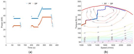
Figure 17.
(a) Engine power; (b) engine operating point.
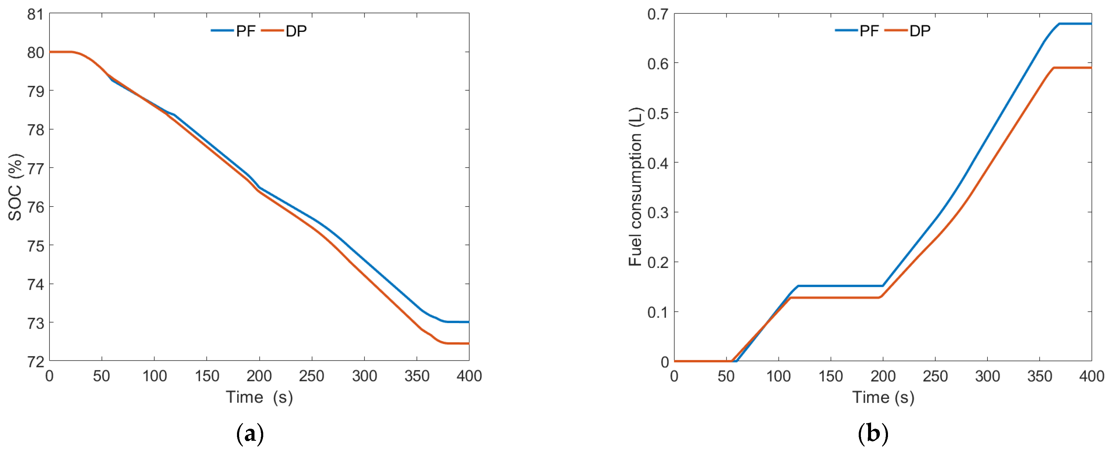
As shown in Figure 18a, the final SOC under the power-following energy management strategy is approximately 73.01%, while the final SOC under the dynamic programming-based energy management strategy is approximately 72.45%. Compared to the power-following energy management strategy, the battery SOC consumed approximately 0.77% more under the dynamic programming-based energy management strategy.
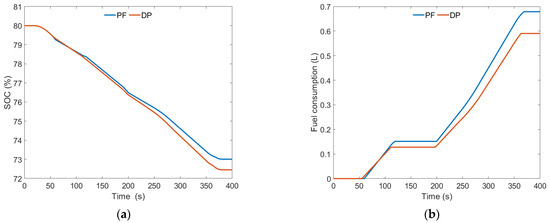
Figure 18.
(a) SOC change curve; (b) fuel consumption change curve.
As shown in Figure 18b, the total fuel consumption under the power-following energy management strategy is 0.68 L, while the total fuel consumption under the dynamic programming-based energy management strategy is 0.59 L. The total fuel consumption decreased by approximately 13.24% under the dynamic programming-based energy management strategy.
6. Discussion
The results of this study emphasize the impact of the proposed energy management strategy for hybrid tractors on fuel economy under various typical operating conditions of tractors. Using the dynamic programming algorithm, the operating status of the engine in a series hybrid tractor was optimized under three typical operating conditions: plowing, rotary tilling, and transportation. Based on the simulation test results, this study provides a comprehensive reference for future related research. The main findings of the discussion are as follows.
The optimization effect of the energy management strategy based on the dynamic programming algorithm is closely related to the operating conditions of the tractor. By analyzing the simulation test results of three typical operating conditions, namely plowing, rotary tilling, and transportation, it is found that, the larger the load of the operating condition, the better the fuel-saving effect of the dynamic programming algorithm compared to the power-following energy management strategy.
According to the simulation test results, the power-following energy management strategy leads to frequent engine starts and stops in both plowing and rotary tilling test conditions. In actual tractor operation, frequent engine starts and stops can further increase fuel consumption. However, the dynamic programming-based energy management strategy does not exhibit frequent engine starts and stops. Future research on energy management strategies should also consider the issue of engine starts and stops.
To better compare the control effects of energy management strategies, it is necessary to consider not only fuel consumption but also the cost impact of battery power consumption. In the simulation tests conducted in this study, the dynamic programming-based energy management strategy optimizes the operating state of the engine based on the entire working conditions. Under the same working conditions, it is difficult to achieve the same final SOC value as the power-following energy management strategy, which has a certain impact on testing the optimization effect of the energy management strategy. Therefore, future research work should also consider issues related to electricity costs.
7. Conclusions
This study describes an energy management strategy for a series hybrid tractor, aiming to achieve optimal fuel consumption throughout the entire operating cycle of the tractor. Firstly, the SOC of the power battery is considered as the state variable, and the engine power is the control variable. Then, the total fuel consumption of the engine throughout the entire set of operating conditions is taken as the objective function. Finally, a series hybrid tractor energy management strategy based on a dynamic programming algorithm is designed. The main conclusions are as follows.
Under the conditions of plowing, rotary tillage, and transportation operations, the total fuel consumption values for the power following-based energy management strategy are 2.65 L, 2.46 L, and 0.68 L, respectively. For the dynamic programming-based energy management strategy, the total fuel consumption values are 1.98 L, 1.93 L, and 0.59 L, respectively. Compared to the power-following energy management strategy, the dynamic programming-based energy management strategy results in an additional consumption of approximately 8.37%, 7.24%, and 0.77% in battery SOC for plowing, rotary tilling, and transportation operations, respectively. Simultaneously, the total fuel consumption of the tractor decreases by approximately 25.28%, 21.54%, and 13.24% for the respective operations.
In this paper, the total workload of the tractor during plowing operations is the highest, followed by rotary tillage operations, and transportation operations have the lowest workload. The trend of total workload change is consistent with the effect of reduced total fuel consumption observed in the simulation results. Specifically, the greater the total workload, the better the fuel-saving effect achieved by the dynamic programming-based energy management strategy compared to the power following-based strategy.
Compared to the power following-based energy management strategy, the dynamic programming-based strategy can better adjust the operating state of the engine, reasonably control the start–stop and output power of the engine, and keep the engine operating in a high-efficiency range.
Author Contributions
Conceptualization, X.Y. and J.Z.; methodology, X.Y. and J.Z.; software, Y.Z.; validation, Y.Z. and X.L.; formal analysis, Y.Z.; investigation, X.Y. and X.L.; resources, X.Y.; data curation, M.L. and Y.W.; writing—original draft preparation, J.Z. and Y.Z.; writing—review and editing, X.Y. and Y.Z.; visualization, Y.Z.; supervision, X.Y.; project administration, X.Y.; funding acquisition, J.Z. and X.Y. All authors have read and agreed to the published version of the manuscript.
Funding
This research has been awarded the “14th Five-Year” national key research and development Plan (2022YFD2001203, 2022YFD2001201B); Agricultural Key Core Technology GG project NK202216010103. This research was funded by the State Key Laboratory of Intelligent Agricultural Power Equipment Open Project (SKLIAPE2023006), Henan University of Science and Technology Innovation Team Support Program (24IRTSTHN029), and Henan Provincial Science and Technology Research Project (222102110233).
Data Availability Statement
The original contributions presented in the study are included in the article, further inquiries can be directed to the corresponding author.
Conflicts of Interest
The authors declare no conflicts of interest.
References
- Mocera, F.; Somà, A.; Martelli, S.; Martini, V. Trends and Future Perspective of Electrification in Agricultural Tractor-Implement Applications. Energies 2023, 16, 6601. [Google Scholar] [CrossRef]
- Wang, Z.; Zhou, J.; Yang, H.; Wang, X. Design and Test of Measurement and Control System for Rapid Prototype Platform Used in Electric Tractors. Nongye Jixie Xuebao Trans. Chin. Soc. Agric. Mach. 2022, 53, 412–420. [Google Scholar] [CrossRef]
- Scolaro, E.; Beligoj, M.; Estevez, M.P.; Alberti, L.; Renzi, M.; Mattetti, M. Electrification of Agricultural Machinery: A Review. IEEE Access 2021, 9, 164520–164541. [Google Scholar] [CrossRef]
- Mocera, F.; Martini, V.; Soma, A. Comparative Analysis of Hybrid Electric Architectures for Specialized Agricultural Tractors. Energies 2022, 15, 1944. [Google Scholar] [CrossRef]
- Xie, B.; Wu, Z.; Mao, E. Development and Prospect of Key Technologies on Agricultural Tractor. Nongye Jixie Xuebao Trans. Chin. Soc. Agric. Mach. 2018, 49, 1–17. [Google Scholar] [CrossRef]
- Chen, Y. Study on Design and Drive Control Methods of Powertrain for Electric Tractor. Ph.D. Thesis, China Agricultural University, Beijing, China, 2018. [Google Scholar]
- Radrizzani, S.; Panzani, G.; Trezza, L.; Pizzocaro, S.; Savaresi, S.M. An Add-On Model Predictive Control Strategy for the Energy Management of Hybrid Electric Tractors. IEEE Trans. Veh. Technol. 2024, 73, 1918–1930. [Google Scholar] [CrossRef]
- Medevepryt, U.K.; Makaras, R.; Lukoeviius, V.; Kerys, A. Evaluation of the Working Parameters of a Series-Hybrid Tractor under the Soil Work Conditions. Teh. Vjesn. 2022, 29, 45–50. [Google Scholar] [CrossRef]
- Wang, B.; Qiao, M.; Chu, X.; Shang, S.; Wang, D. Design and Experiment on Extended-Range Electric Caterpillar Tractor. Nongye Jixie Xuebao Trans. Chin. Soc. Agric. Mach. 2023, 54, 431–439. [Google Scholar] [CrossRef]
- Medževeprytė, U.K.; Makaras, R.; Lukoševičius, V.; Kilikevičius, S. Application and Efficiency of a Series-Hybrid Drive for Agricultural Use Based on a Modified Version of the World Harmonized Transient Cycle. Energies 2023, 16, 5379. [Google Scholar] [CrossRef]
- Zhu, Z.; Zeng, L.; Chen, L.; Zou, R.; Cai, Y. Fuzzy Adaptive Energy Management Strategy for a Hybrid Agricultural Tractor Equipped with HMCVT. Agriculture 2022, 12, 1986. [Google Scholar] [CrossRef]
- Li, T.; Cui, W.; Cui, N. Soft Actor-Critic Algorithm-Based Energy Management Strategy for Plug-In Hybrid Electric Vehicle. World Electr. Veh. J. 2022, 13, 193. [Google Scholar] [CrossRef]
- He, H.; Meng, X. A Review on Energy Management Technology of Hybrid Electric Vehicles. Beijing Ligong Daxue Xuebao Trans. Beijing Inst. Technol. 2022, 42, 773–783. [Google Scholar] [CrossRef]
- Yang, C.; Zha, M.; Wang, W.; Liu, K.; Xiang, C. Efficient Energy Management Strategy for Hybrid Electric Vehicles/Plug-in Hybrid Electric Vehicles: Review and Recent Advances under Intelligent Transportation System. IET Intell. Transp. Syst. 2020, 14, 702–711. [Google Scholar] [CrossRef]
- Chen, Y.; Wei, C.; Li, X.; Li, Y.; Liu, C.; Lin, X. Research on Fuzzy Energy Management Strategy for Extended-Range Electric Vehicles with Driving Condition Identification. Qiche Gongcheng Automot. Eng. 2022, 44, 514–524+600. [Google Scholar] [CrossRef]
- Yang, H.; Sun, Y.; Xia, C.; Zhang, H. Research on Energy Management Strategy of Fuel Cell Electric Tractor Based on Multi-Algorithm Fusion and Optimization. Energies 2022, 15, 6389. [Google Scholar] [CrossRef]
- Zou, K.; Luo, W.; Lu, Z. Real-Time Energy Management Strategy of Hydrogen Fuel Cell Hybrid Electric Vehicles Based on Power Following Strategy–Fuzzy Logic Control Strategy Hybrid Control. World Electr. Veh. J. 2023, 14, 315. [Google Scholar] [CrossRef]
- Zhu, Z.; Zeng, L.; Lin, Y.; Chen, L.; Zou, R.; Cai, Y. Adaptive Energy Management Strategy for Hybrid Tractors Based on Condition Prediction. Hsi-Chiao Tung Ta Hsueh J. Xian Jiaotong Univ. 2023, 57, 201–210. [Google Scholar] [CrossRef]
- Cao, Y.; Yao, M.; Sun, X. An Overview of Modelling and Energy Management Strategies for Hybrid Electric Vehicles. Appl. Sci. 2023, 13, 5947. [Google Scholar] [CrossRef]
- Xu, B.; Shi, J.; Li, S.; Li, H. A Study of Vehicle Driving Condition Recognition Using Supervised Learning Methods. IEEE Trans. Transp. Electrif. 2022, 8, 1665–1673. [Google Scholar] [CrossRef]
- Wu, Y.; Tan, H.; Peng, J.; Zhang, H.; He, H. Deep Reinforcement Learning of Energy Management with Continuous Control Strategy and Traffic Information for a Series-Parallel Plug-in Hybrid Electric Bus. Appl. Energy 2019, 247, 454–466. [Google Scholar] [CrossRef]
- Wang, Y.; Tan, H.; Wu, Y.; Peng, J. Hybrid Electric Vehicle Energy Management with Computer Vision and Deep Reinforcement Learning. IEEE Trans. Ind. Inform. 2021, 17, 3857–3868. [Google Scholar] [CrossRef]
- Yu, P.; Li, M.; Wang, Y.; Chen, Z. Fuel Cell Hybrid Electric Vehicles: A Review of Topologies and Energy Management Strategies. World Electr. Veh. J. 2022, 13, 172. [Google Scholar] [CrossRef]
- Zhu, Y.; Li, X.; Liu, Q.; Li, S.; Xu, Y. Review Article: A Comprehensive Review of Energy Management Strategies for Hybrid Electric Vehicles. Mech. Sci. 2022, 13, 147–188. [Google Scholar] [CrossRef]
- Zhao, S.; Gao, Z.; Li, X.; Li, Y.; Xu, L. Research on Energy Management Strategy of Fuel Cell Tractor Hybrid Power System. World Electr. Veh. J. 2024, 15, 61. [Google Scholar] [CrossRef]
- Dou, H.; Wei, H.; Ai, Q.; Zhang, Y. Optimal Energy Management Strategy for Dual-Power Coupling Tractor Based on the Adaptive Control Technology. PLoS ONE 2023, 18, e0292510. [Google Scholar] [CrossRef] [PubMed]
- Curiel-Olivares, G.; Johnson, S.; Escobar, G.; Schacht-Rodriguez, R. Model Predictive Control-Based Energy Management System for a Hybrid Electric Agricultural Tractor. IEEE Access 2023, 11, 118801–118811. [Google Scholar] [CrossRef]
- Du, C.; Huang, S.; Jiang, Y.; Wu, D.; Li, Y. Optimization of Energy Management Strategy for Fuel Cell Hybrid Electric Vehicles Based on Dynamic Programming. Energies 2022, 15, 4325. [Google Scholar] [CrossRef]
- Pan, C.; Liang, Y.; Chen, L.; Chen, L. Optimal Control for Hybrid Energy Storage Electric Vehicle to Achieve Energy Saving Using Dynamic Programming Approach. Energies 2019, 12, 588. [Google Scholar] [CrossRef]
- Jin, H.; Zhang, Z. Review of Research on HEV Energy Management Based on Adaptive Dynamic Programming. Qiche Gongcheng Automot. Eng. 2020, 42, 1490–1496. [Google Scholar] [CrossRef]
- Wu, K. Simulation and Analysis of the Performance and Energy Management Strategies for Extended-Range Electric Tractors. Master’s Thesis, Northwest A&F University, Xianyang, China, 2022. [Google Scholar]
- Wang, Z.; Zhou, J.; Wang, X. Research on Energy Management Model for Extended-Range Electric Rotary-Tilling Tractor. Nongye Jixie Xuebao Trans. Chin. Soc. Agric. Mach. 2023, 54, 428–438. [Google Scholar] [CrossRef]
- Li, T.; Xie, B.; Wang, D.; Zhang, S.; Wu, L. Real-Time Adaptive Energy Management Strategy for Dual-Motor-Driven Electric Tractors. Nongye Jixie Xuebao Trans. Chin. Soc. Agric. Mach. 2020, 51, 530–543. [Google Scholar] [CrossRef]
- Zhou, R. Study on Energy Distribution Strategy of Tandem Hybrid Tractor under Different Working Conditions. Master’s Thesis, Nanjing Agricultural University, Nanjing, China, 2020. [Google Scholar]
- Dou, H.; Wei, H.; Ai, Q.; Zhang, Y. Control Strategy for Rotary Tillage Condition of Hybrid Electric Tractor with Coupled-Split Dynamic Configuration. Nongye Jixie Xuebao Trans. Chin. Soc. Agric. Mach. 2024, 55, 393–400+414. [Google Scholar] [CrossRef]


Disclaimer/Publisher’s Note: The statements, opinions and data contained in all publications are solely those of the individual author(s) and contributor(s) and not of MDPI and/or the editor(s). MDPI and/or the editor(s) disclaim responsibility for any injury to people or property resulting from any ideas, methods, instructions or products referred to in the content. |
© 2024 by the authors. Licensee MDPI, Basel, Switzerland. This article is an open access article distributed under the terms and conditions of the Creative Commons Attribution (CC BY) license (https://creativecommons.org/licenses/by/4.0/).