

Torque Ripple Reduction in Brushless Wound Rotor Vernier Machine Using Third-Harmonic Multi-Layer Winding


Abstract
1. Introduction
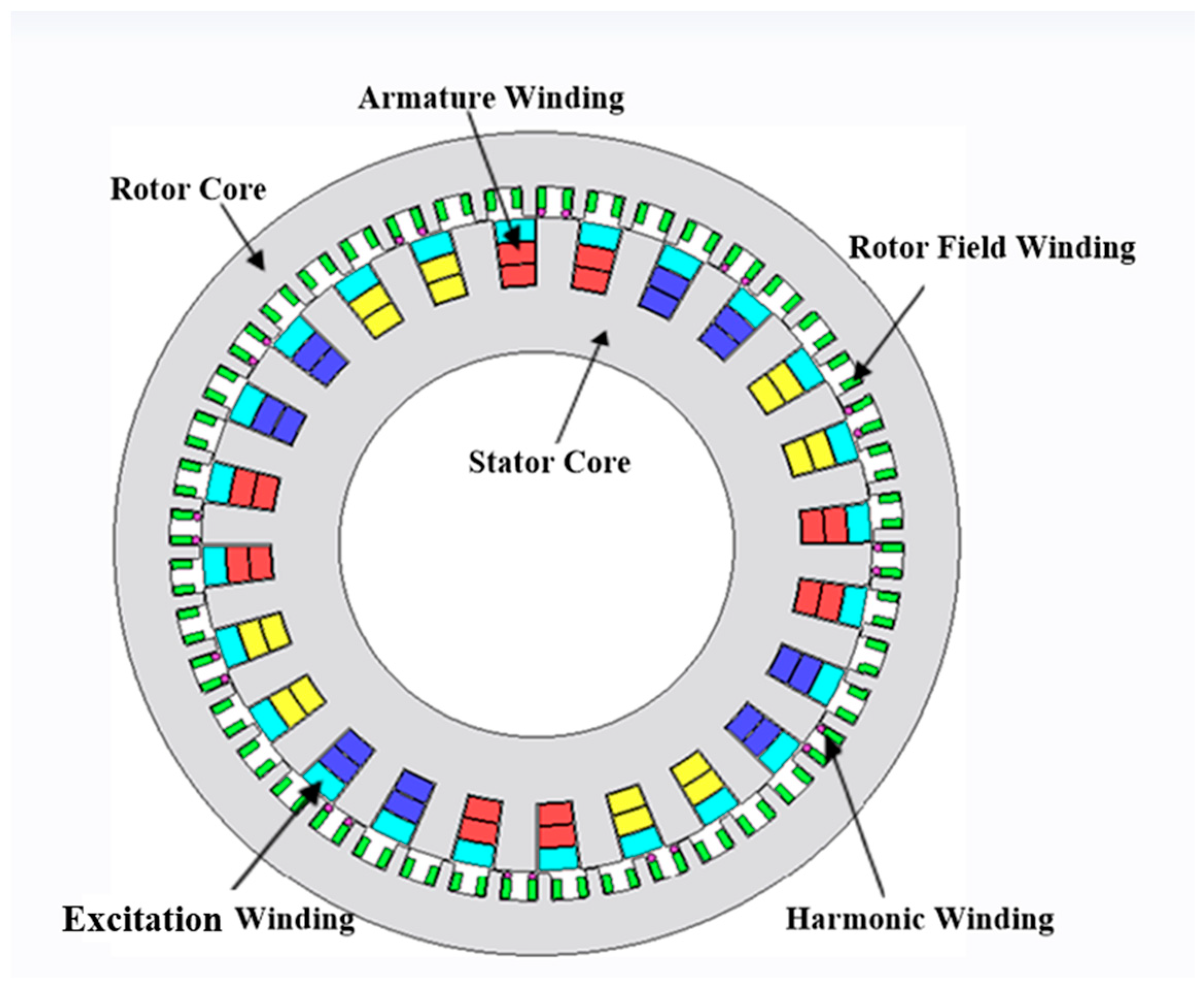
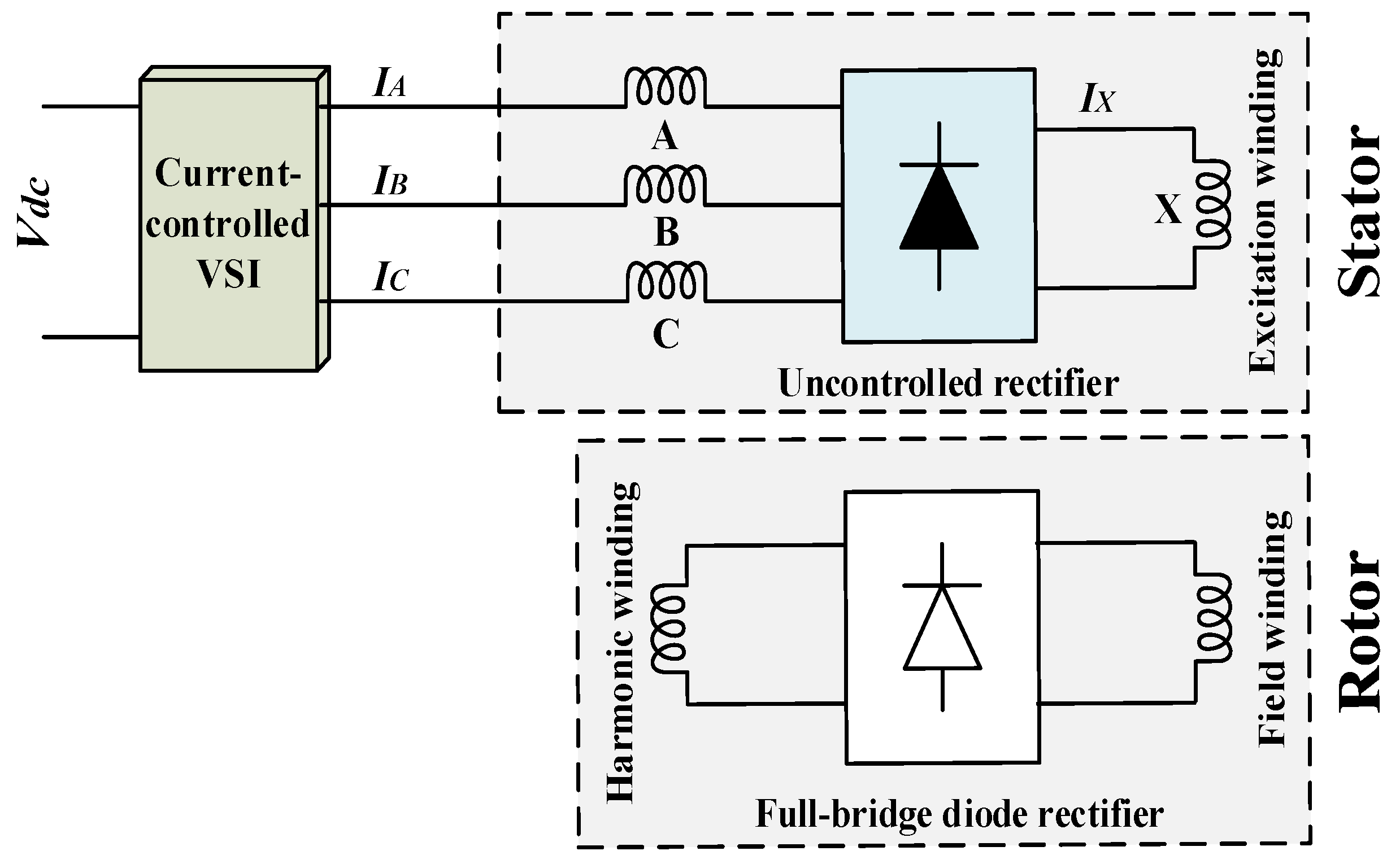
2. Conventional Brushless WRVM Topology
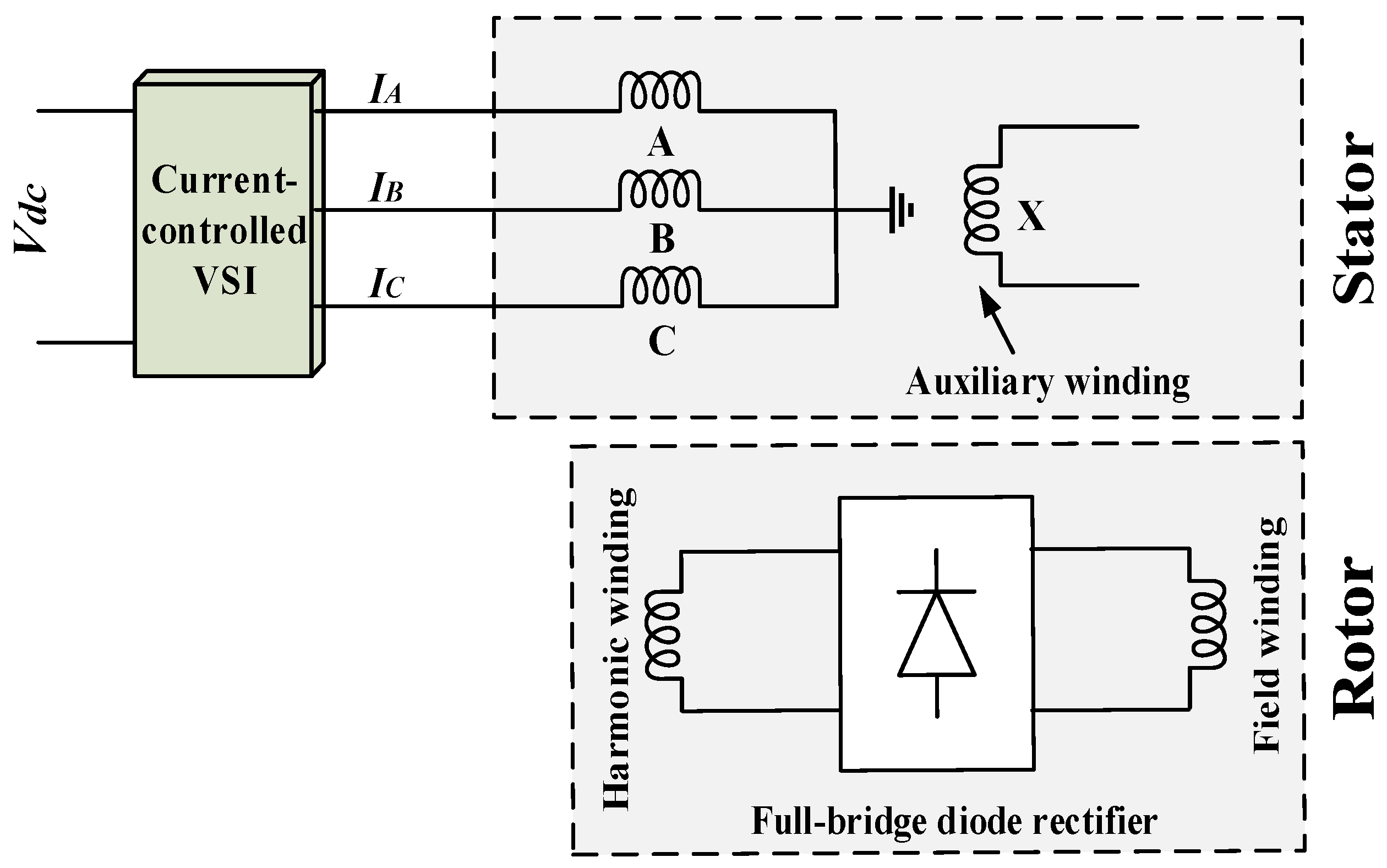
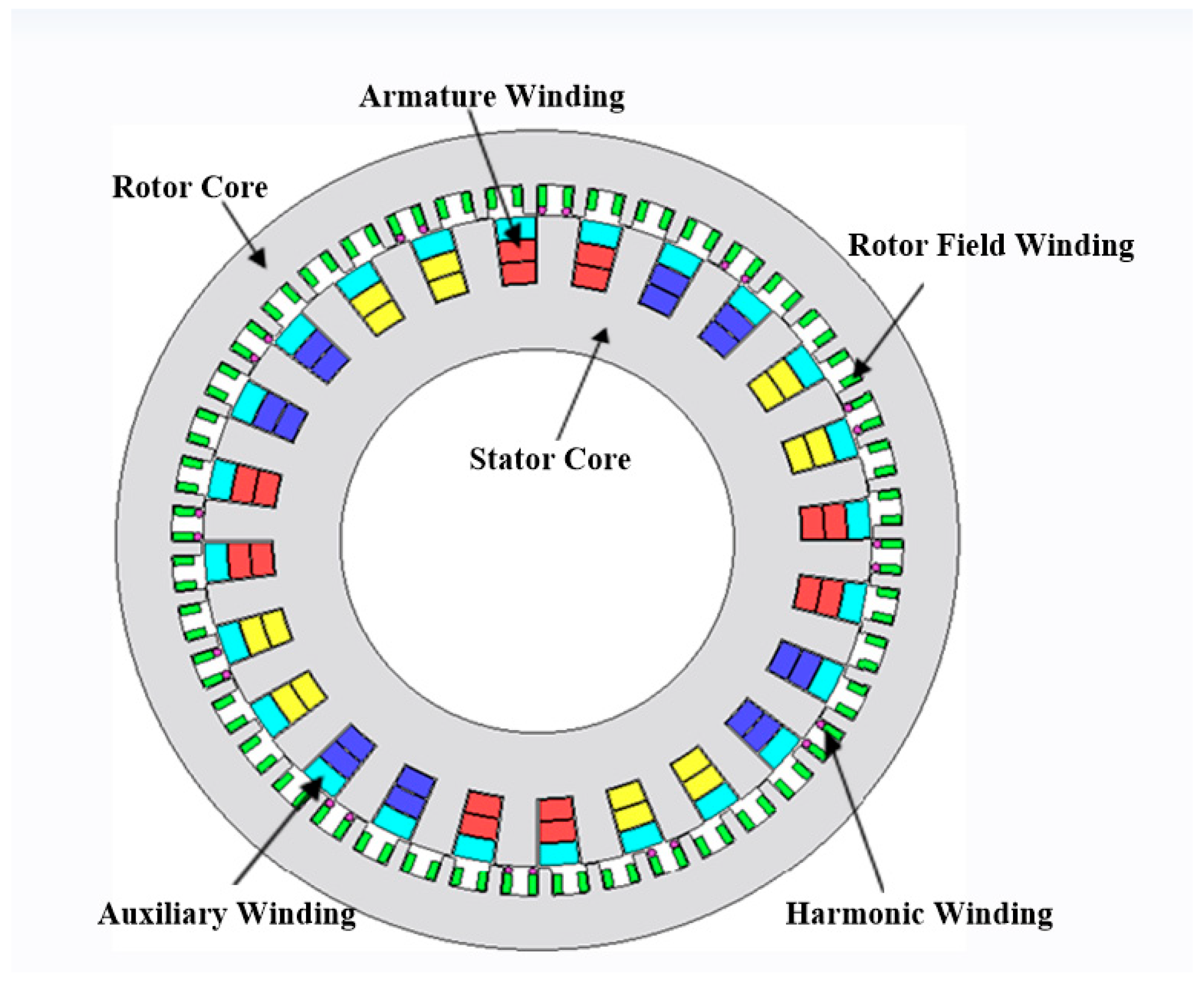
3. Proposed Brushless WRVM Topology
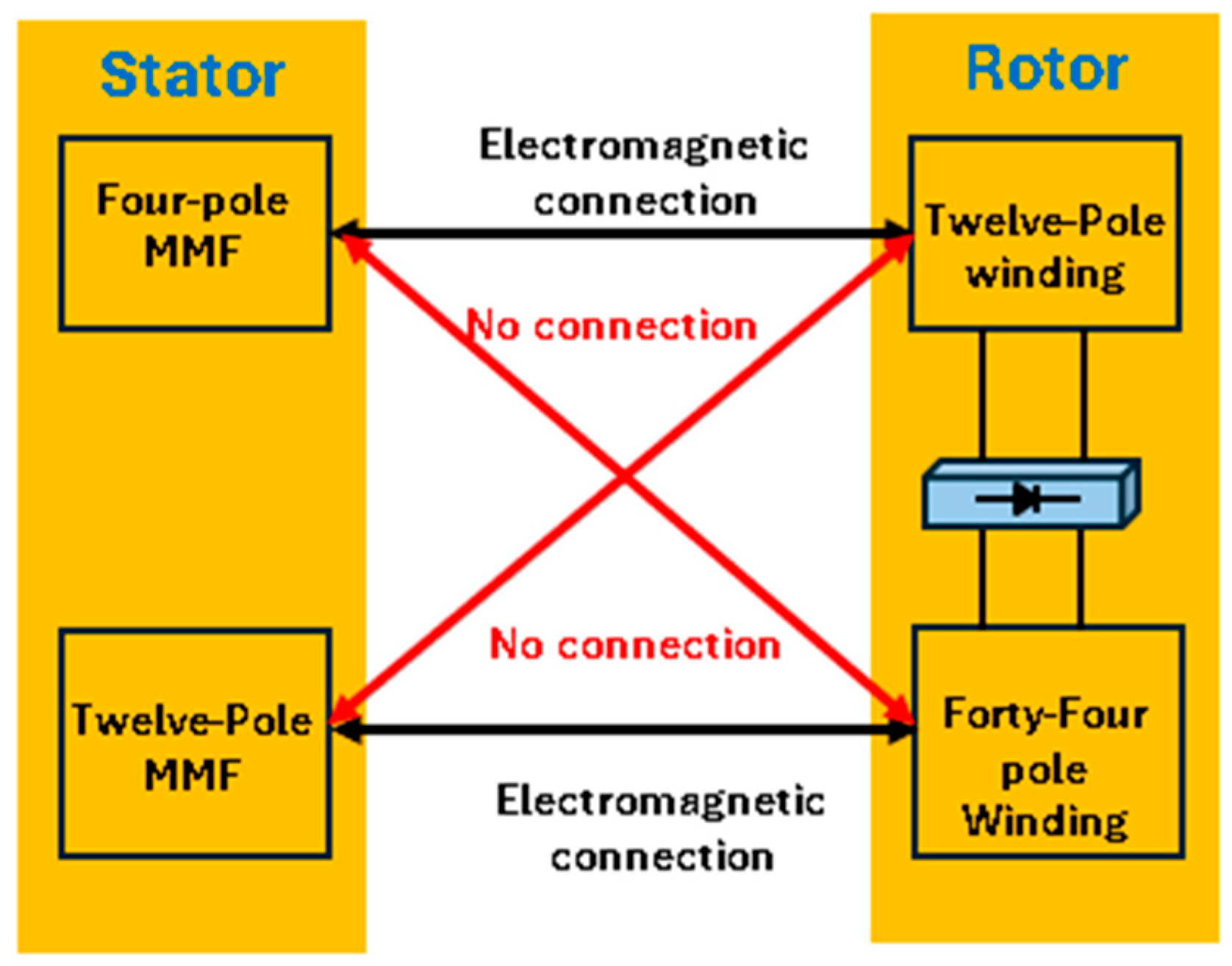
Operating Principle
- Rotational speed of the machine;
- Flux in the machine;
- Basic construction (geometry) of the machine.
4. Design and 2D Finite Element Analysis of the Proposed Brushless WRVM Topology
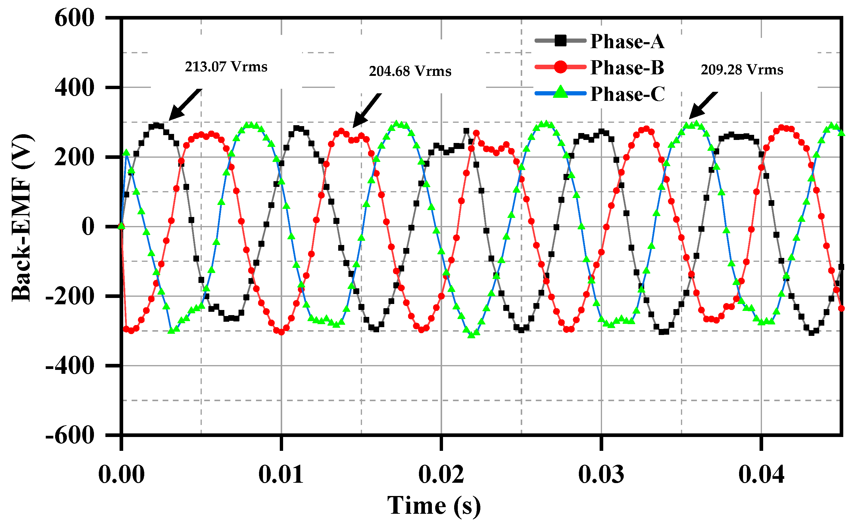
4.1. No-Load Case Analysis
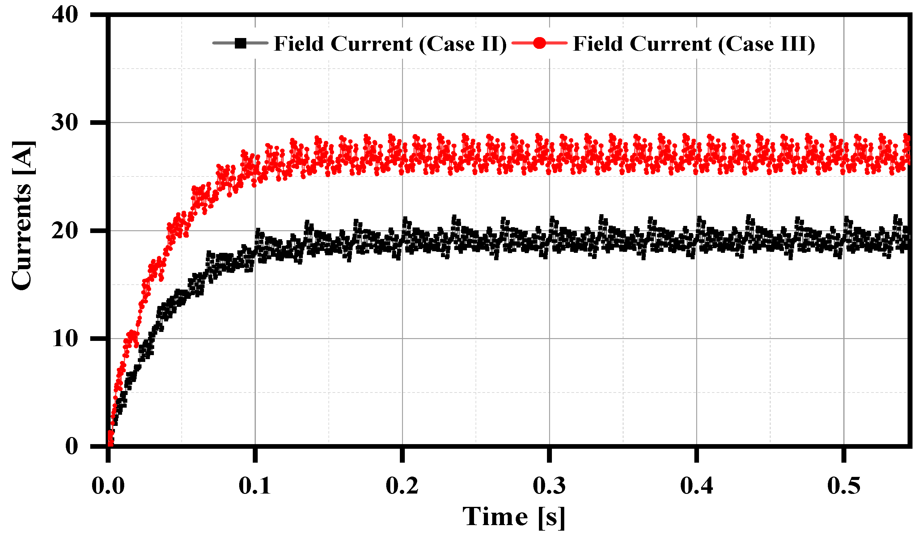
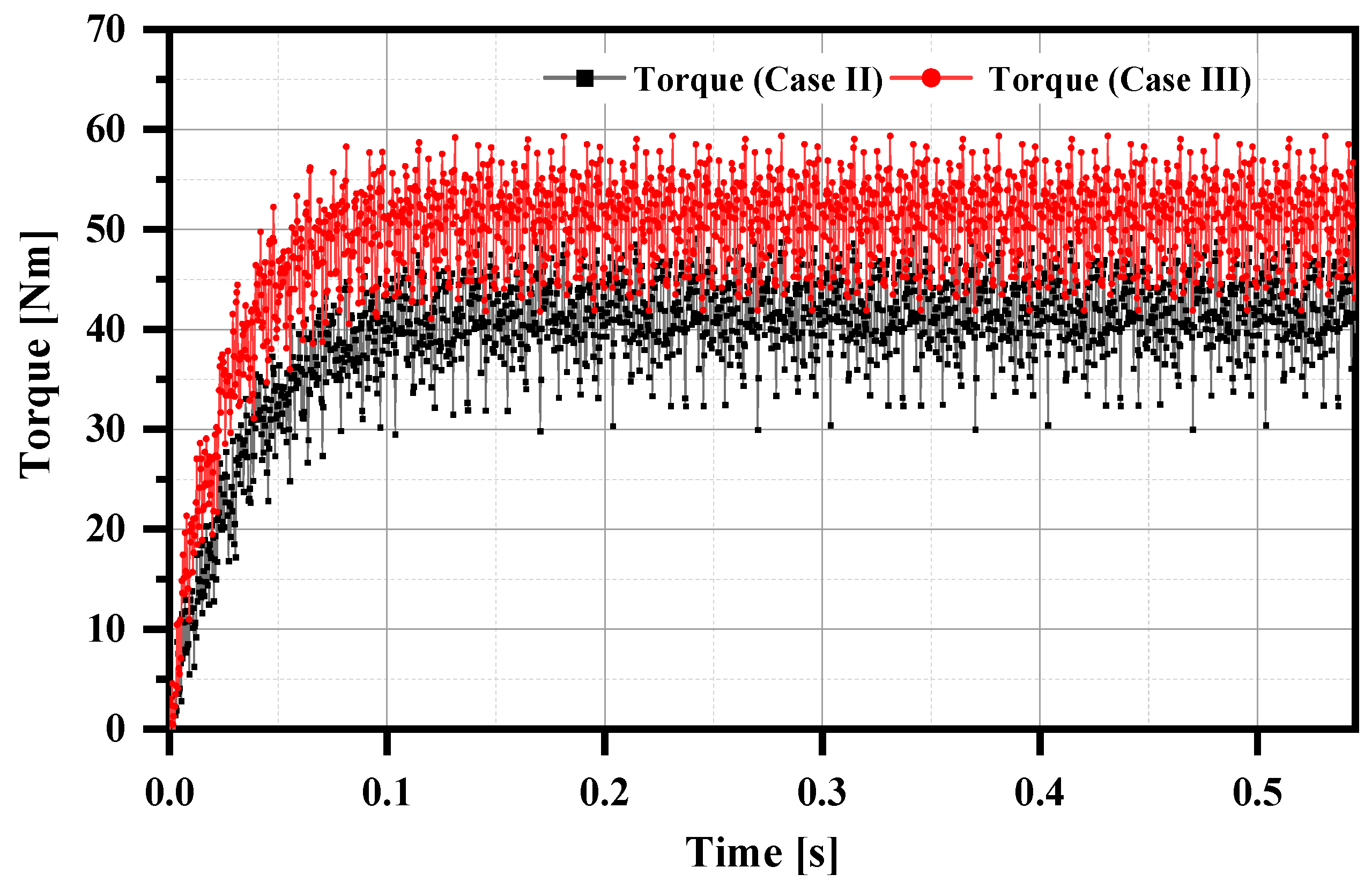
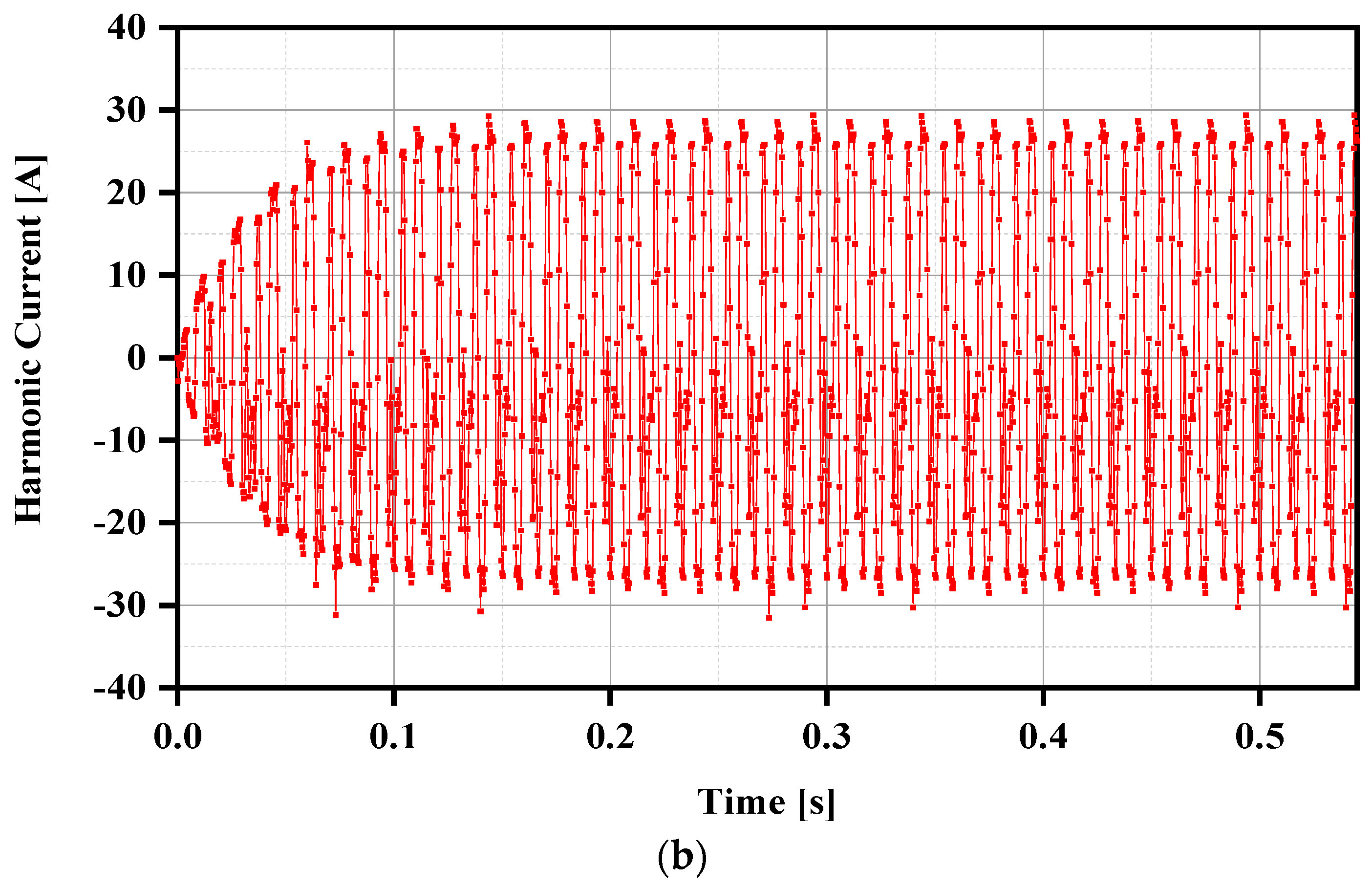
4.2. Load Case Analysis
5. Comparative Analysis
6. Conclusions
Author Contributions
Funding
Data Availability Statement
Conflicts of Interest
References
- Du, Z.S.; Lipo, T.A. Efficient Utilization of Rare Earth Permanent-Magnet Materials and Torque Ripple Reduction in Interior Permanent-Magnet Machines. IEEE Trans. Ind. Appl. 2017, 53, 3485–3495. [Google Scholar] [CrossRef]
- Barcaro, M.; Bianchi, N. Interior PM Machines Using Ferrite to Replace Rare-Earth Surface PM Machines. IEEE Trans. Ind. Appl. 2013, 50, 979–985. [Google Scholar] [CrossRef]
- Bash, M.; Pekarek, S.; Sudhoff, S.; Whitmore, J.; Frantzen, M. A comparison of permanent magnet and wound rotor synchronous machines for portable power generation. In Proceedings of the IEEE 2010 Power and Energy Conference at Illinois (PECI), Urbana, IL, USA, 12–13 February 2010. [Google Scholar]
- Ali, Q.; Lipo, T.A.; Kwon, B.-I. Design and Analysis of a Novel Brushless Wound Rotor Synchronous Machine. IEEE Trans. Magn. 2015, 51, 8109804. [Google Scholar] [CrossRef]
- Ayub, M.; Hussain, A.; Jawad, G.; Kwon, B.-I. Brushless Operation of a Wound-Field Synchronous Machine Using a Novel Winding Scheme. IEEE Trans. Magn. 2019, 55, 8201104. [Google Scholar] [CrossRef]
- Humza, M.; Yazdan, T.; Ali, Q.; Cho, H.W. Brushless Operation of Wound-Rotor Synchronous Machine Based on Sub-Harmonic Excitation Technique Using Multi-Pole Stator Windings. Mathematics 2023, 11, 1117. [Google Scholar] [CrossRef]
- Humza, M.; Yazdan, T.; Siddiqi, M.R.; Wook-Cho, H. Brushless Wound Rotor Vernier Motor Using Single-Phase Additional Winding on Stator for Variable Speed Applications. IEEE Access 2023, 11, 86262–86270. [Google Scholar] [CrossRef]
- Bukhari, S.S.H.; Shah, M.A.; Rodas, J.; Bajaj, M.; Ro, J.-S. Novel sub-harmonic-based self-excited brushless wound rotor synchronous machine. IEEE Can. J. Electr. Comput. Eng. 2022, 45, 365–374. [Google Scholar] [CrossRef]
- Jawad, G.; Ali, Q.; Lipo, T.A.; Kwon, B.-l. Novel Brushless Wound Rotor Synchronous Machine with Zero Sequence Third Harmonic Field Excitation. IEEE Trans. Magn. 2016, 52, 1. [Google Scholar] [CrossRef]
- An, Q.; Gao, X.; Yao, F.; Sun, L.; Lipo, T. The structure optimization of novel harmonic current excited brushless synchronous machines based on open winding pattern. In Proceedings of the 2014 IEEE Energy Conversion Congress and Exposition (ECCE), Pittsburgh, PA, USA, 15–18 September 2014; pp. 1754–1761. [Google Scholar]
- Sirewal, G.J.; Ayub, M.; Atiq, S.; Kwon, B.I. Analysis of a brushless wound rotor synchronous machine employing a stator harmonic winding. IEEE Access. 2020, 8, 151392–151402. [Google Scholar] [CrossRef]
- Ali, Q.; Hussain, A.; Baloch, N.; Kwon, B.I. Design and Optimization of a Brushless Wound-Rotor Vernier Machine. Energies 2018, 11, 317. [Google Scholar] [CrossRef]
- Tariq, S.; Ikram, J.; Bukhari, S.S.H.; Ali, Q.; Hussain, A.; Ro, J.-S. Design and Analysis of Single Inverter-Fed Brushless Wound Rotor Vernier Machine. IEEE Access 2022, 10, 101609–101621. [Google Scholar] [CrossRef]
- Bukhari, S.S.H.; Ikram, J.; Wang, F.; Yu, X.; Imtiaz, J.; Rodas, J.; Ro, J.-S. Novel Self-Excited Brush-Less Wound Field Vernier Machine Topology. IEEE Access 2022, 10, 97868–97878. [Google Scholar] [CrossRef]
- Hammad, S.Y.; Ikram, J.; Badar, R.; Bukhari, S.S.H.; Khan, L.; Ro, J.-S. Performance Analysis of Brushless Wound Rotor Vernier Machine by Utilizing Third Harmonic Field Excitation. IEEE Access 2023, 11, 65480–65490. [Google Scholar] [CrossRef]


| Parameters | Units | Conventional Model | Proposed Model |
|---|---|---|---|
| Stator poles | - | 4 | 4 |
| Stator slots | - | 24 | 24 |
| Stator inner diameter | mm | 140 | 140 |
| Stator outer diameter | mm | 238 | 238 |
| Stator winding turns | - | 90 | 90 |
| Rotor field winding turns | - | 36 | 36 |
| Rotor harmonic winding tuns | - | 6 | 6 |
| Stator excitation winding turns | - | 90 | 24 |
| Rotor field poles | - | 44 | 44 |
| Rotor slots | - | 44 | 44 |
| Rotor inner diameter | mm | 239 | 239 |
| Rotor outer diameter | mm | 300 | 300 |
| Stator XYZ winding turns | - | 90 | 90 |
| Stator XYZ poles | - | 2 | 2 |
| Slots for XYZ winding | - | 6 | 6 |
| Operating speed | rpm | 300 | 300 |
| Airgap | mm | 0.5 | 0.5 |
| Parameters | Unit | Conventional Topology | Proposed Topology (Case I) | Proposed Topology (Case II) | Proposed Topology (Case III) |
|---|---|---|---|---|---|
| Armature currents | [A] | ABC = 2.12 (rms) X carries 5.32 (rms) | ABC = 2.12 (rms) X carries no current | 5.32 (rms) | 5.32 (rms) |
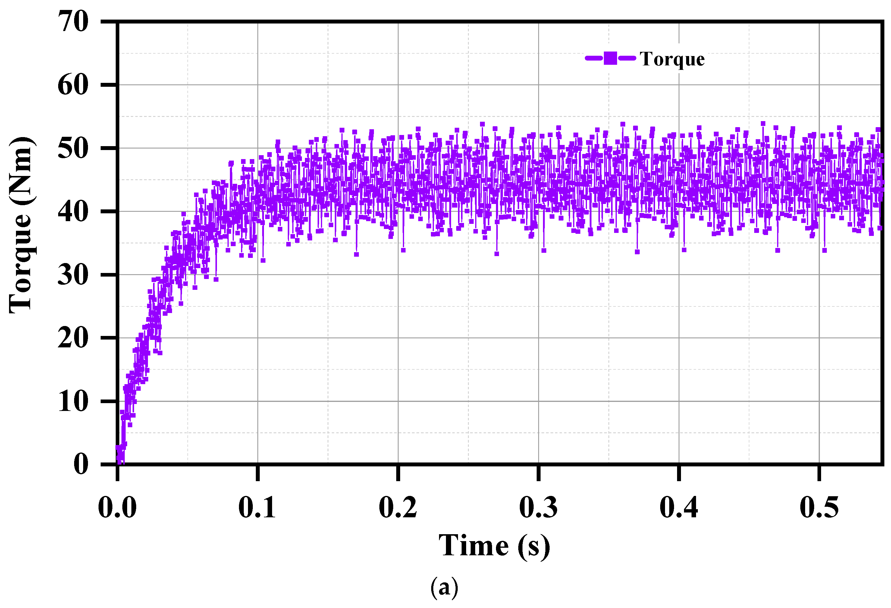
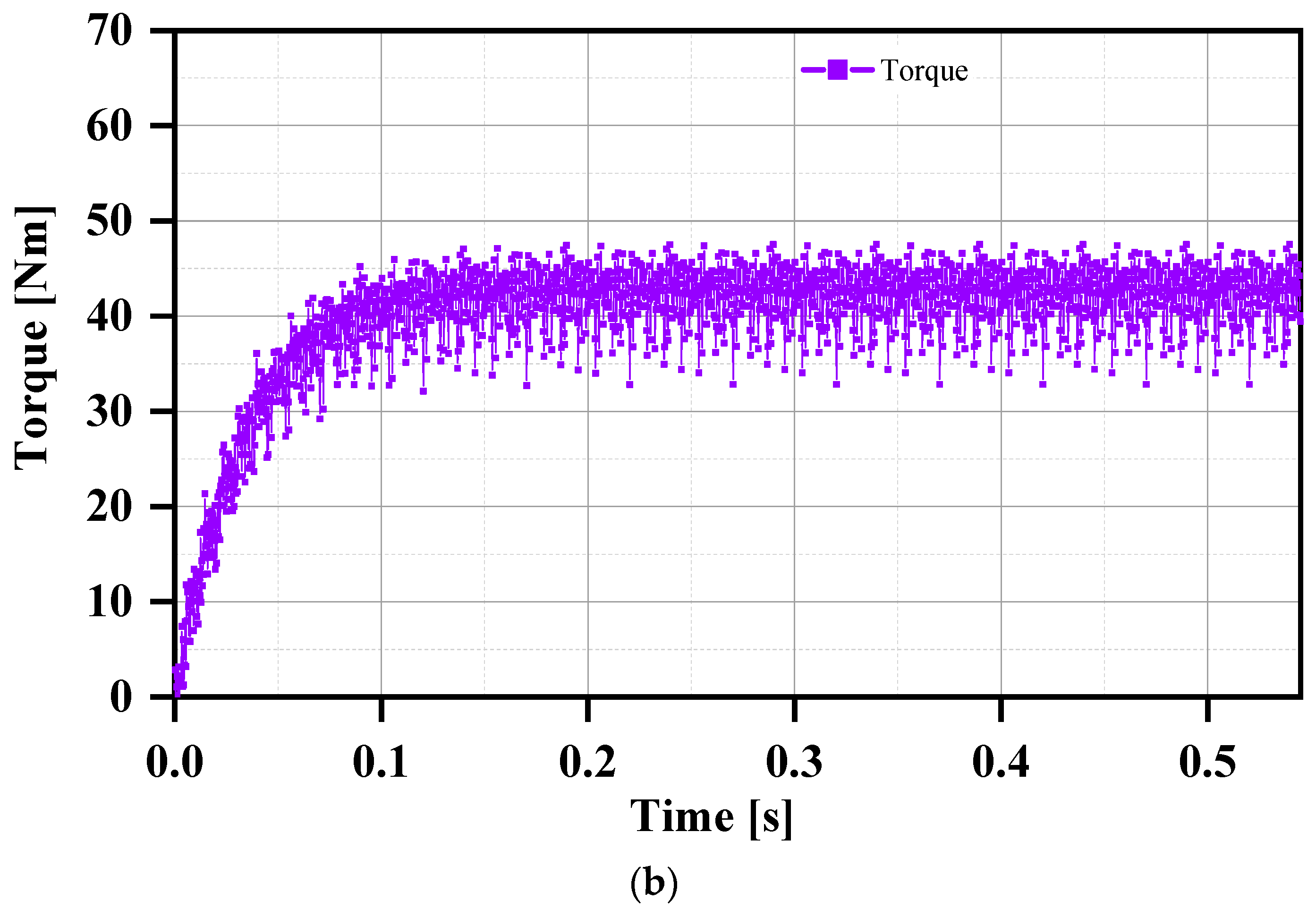
| Torque | [Nm] | 41.91 | 39.74 | 39.23 | 48.8 |
| Torque ripple | % | 49 | 36.90 | 36.52 | 35.68 |
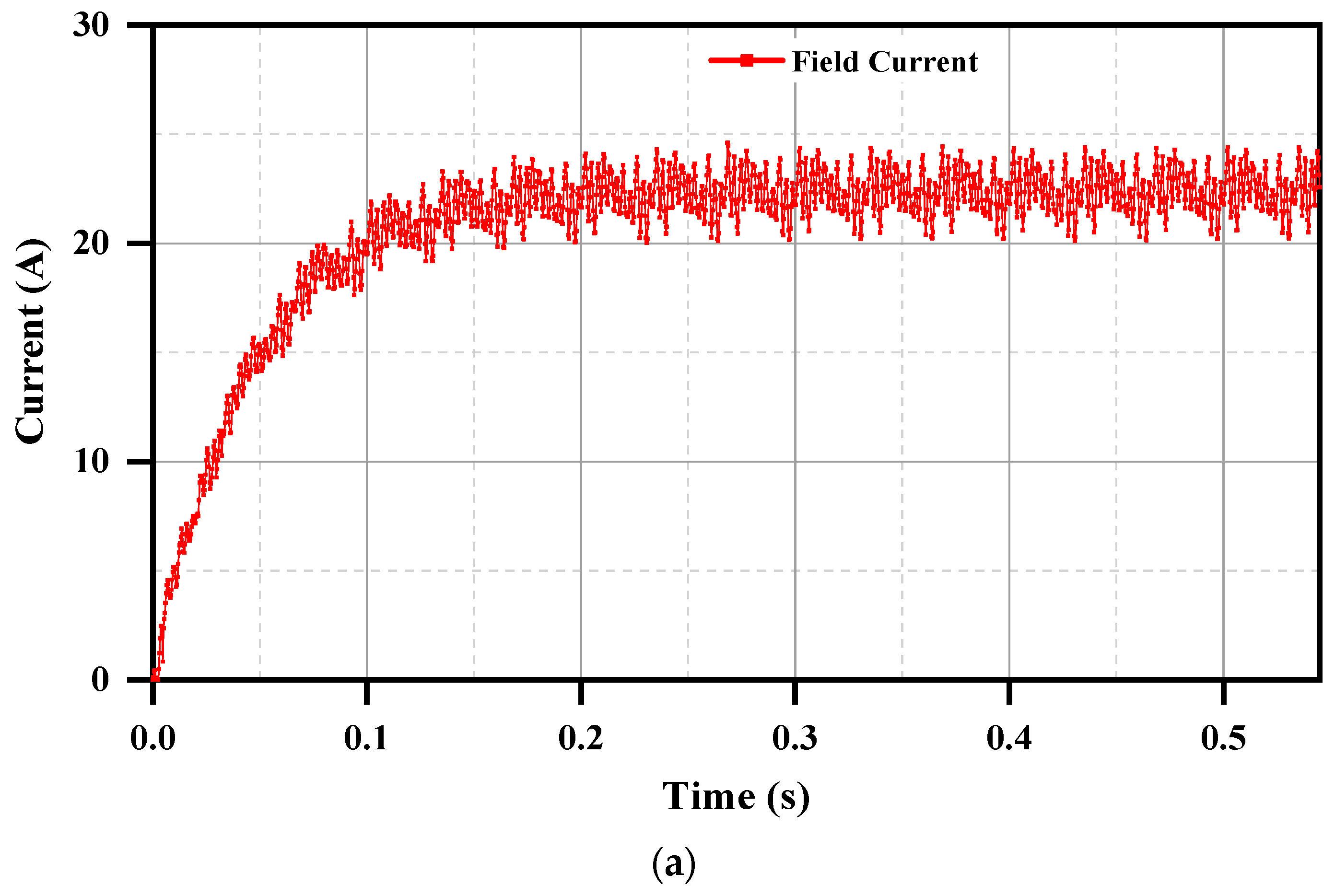
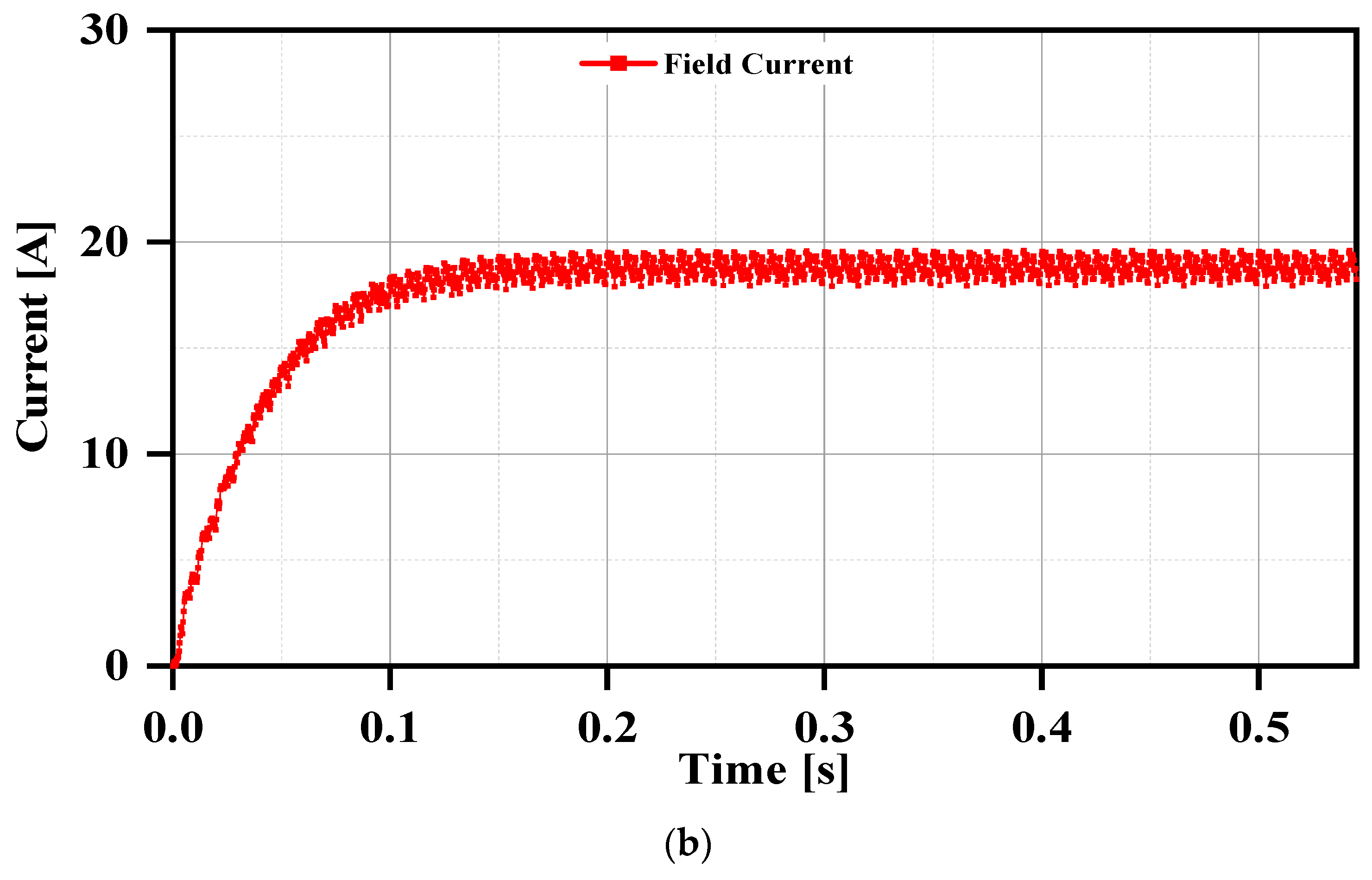
| Field current | [A] | 20.55 | 17.53 | 17.85 | 25.51 |
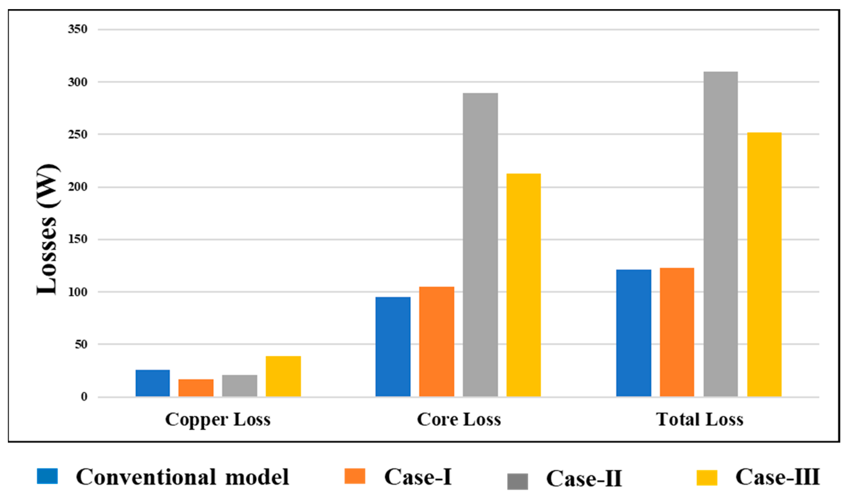
| Copper losses | [W] | 25.98 | 17.17 | 21.07 | 38.94 |
| Core losses | [W] | 95.02 | 105.09 | 289.06 | 212.77 |
| Total losses | [W] | 121 | 122.8 | 310.13 | 251.71 |
| Output power | [W] | 1661.84 | 1588.2 | 1576 | 1863.34 |
| Efficiency | 93.21 | 93 | 83.55 | 88.09 |
Disclaimer/Publisher’s Note: The statements, opinions and data contained in all publications are solely those of the individual author(s) and contributor(s) and not of MDPI and/or the editor(s). MDPI and/or the editor(s) disclaim responsibility for any injury to people or property resulting from any ideas, methods, instructions or products referred to in the content. |
© 2024 by the authors. Licensee MDPI, Basel, Switzerland. This article is an open access article distributed under the terms and conditions of the Creative Commons Attribution (CC BY) license (https://creativecommons.org/licenses/by/4.0/).
Share and Cite
Zulqarnain, M.; Hammad, S.Y.; Ikram, J.; Bukhari, S.S.H.; Khan, L. Torque Ripple Reduction in Brushless Wound Rotor Vernier Machine Using Third-Harmonic Multi-Layer Winding. World Electr. Veh. J. 2024, 15, 163. https://doi.org/10.3390/wevj15040163
Zulqarnain M, Hammad SY, Ikram J, Bukhari SSH, Khan L. Torque Ripple Reduction in Brushless Wound Rotor Vernier Machine Using Third-Harmonic Multi-Layer Winding. World Electric Vehicle Journal. 2024; 15(4):163. https://doi.org/10.3390/wevj15040163
Chicago/Turabian StyleZulqarnain, Muhammad, Sheikh Yasir Hammad, Junaid Ikram, Syed Sabir Hussain Bukhari, and Laiq Khan. 2024. "Torque Ripple Reduction in Brushless Wound Rotor Vernier Machine Using Third-Harmonic Multi-Layer Winding" World Electric Vehicle Journal 15, no. 4: 163. https://doi.org/10.3390/wevj15040163
APA StyleZulqarnain, M., Hammad, S. Y., Ikram, J., Bukhari, S. S. H., & Khan, L. (2024). Torque Ripple Reduction in Brushless Wound Rotor Vernier Machine Using Third-Harmonic Multi-Layer Winding. World Electric Vehicle Journal, 15(4), 163. https://doi.org/10.3390/wevj15040163