Article

Design and Analysis Models with PID and PID Fuzzy Controllers for Six-Phase Drive

Department of Electrical Engineering and Electronics, Vilnius College of Technologies and Design, Antakalnio Str. 54, LT-10303 Vilnius, Lithuania
*
Author to whom correspondence should be addressed.
World Electr. Veh. J. 2024, 15(4), 164; https://doi.org/10.3390/wevj15040164
Submission received: 31 January 2024 / Revised: 3 April 2024 / Accepted: 4 April 2024 / Published: 12 April 2024
(This article belongs to the Special Issue New Trends in Electrical Drives for EV Applications)

Abstract

:
Due to their reliability, design and analysis models with PID and PID fuzzy controllers for six-phase drive are being applied in new areas in various industries, including transportation. First, the development of any system with multiphase motors requires an elaborate model to define the control mode and controllers. The modeling of a control system for six-phase drive is based on its conventional d-q mathematical model and indirect field-oriented control. In this study, a Simulink six-phase drive model is designed with indirect field-oriented control and simulated with two types of fuzzy controller, PID and PID fuzzy. The simulation results are presented and analyzed; these results reflect the step response and performance at the provided speed reference law while keeping the load application at a constant speed. A fuzzy controller with 49 rules is considered and applied. With field-oriented control and a well-tuned PID controller, the six-phase electric drive has good step response specifications: a short settling time when starting without a load, no overshoot in the step response, small size, and a slight decrease in speed when loaded. The system employing a PID fuzzy controller shows slightly better results in response to the application of torque: the decrease in speed is eliminated more quickly. The simulation results were tabulated with the PID and with the results of previous research that rearranged some models to only operate in the classical controller mode. The simulation results indicate the robustness to disturbance of both the systems with six-phase drive and provide high-quality transient specifications at the provided reference speed.

1. Introduction

The continuous perfecting and upgrading of electronic devices have facilitated the development of multiphase motors. Polyphase motors have been applied in different electric drives with controlled speed [1], in railway vehicle traction systems [2], and in cars [3]. When employed in submarines used as warships, they reduce noise [4]. Specialized multiphase motors can be used to drive centrifugal pumps [5], as well as in the electronic differentials of electric vehicles [6], in both automotive and electrical vehicles [7,8], and in other types of electrical aircraft [9].
Multiphase motors are called phase-redundant AC drives. The greater number of phase windings distribute the controlled power to more converter legs and reduce the current of electronic power switches. With the smaller current flow in the phase windings of induction electric drives, as well as the fact that multiphase motors are designed to reduce both the phase current flow and copper loss, it is possible to achieve electric drives and control electronics of smaller sizes and weights.
Multiphase motors and drives with redundant phase numbers are characterized by high reliability: albeit with greater losses, they are able to successfully operate under faulty conditions up to single windings. However, they are not able to start without three supplied windings [10,11,12,13].
Six-phase motors can be produced in two ways: by keeping the same winding and commutating that to obtain six phases [14]. Then, the angle between phases becomes 30 degrees; these are called asymmetrical induction machines. The other method relies on removing the old windings and replacing them with new designs with sixty spatial degrees of displacement. This is called a symmetrical machine. When used for its desired application, this type of machine operates as a three- or six-phase machine. We will use this type of motor to develop our controlled electric drive.
A motor’s dynamic performance can be described using state–space equations. The solutions of such equations can provide information about the dynamic and steady-state performance of multiphase motor drives. Analyzing drive behavior and designing methods for control are reasonable approaches to improving this performance.
Simulink models have several advantages. They can be constructed from separate Simulink blocks to simulate the system and facilitate the analysis of the results. Solutions of state–space equations [15,16,17] and Simulink models can be applied to account for the dynamics of multiphase drives.
Equations that describe multiphase motor performance contain constantly varying inductances between the rotor and stator phases due to rotation; they include nonlinear features of the controlled system and therefore can be difficult to solve. Designed Simulink models are more appropriate and more reasonable due to the fact that they not only include the motor drive but also its control equipment [18,19,20,21]. Simulation models can be applied for system computer control.
There are two different ways to simulate six-phase induction motors. One of them assumes they function similarly to three-phase motors and simulate them as such [15]. Addressing the advantages of built-in Simulink blocks, the authors of [15] used a simulated non-controlled six-phase motor with a rotating reference frame. The other way was used in [4,22], where equations describing two sets of windings with a d-q reference frame were used. Due to the shortage of built-in Simulink blocks, a non-controlled six-phase induction motor was modeled in [4,15,22].
A six-phase electric drive can employ all the same control methods used for three-phase motors. Three-phase control techniques can be applied to the three windings of six-phase motors; several subsets make for multiphase windings. A multiphase inverter is used as three-phase converters can control these windings separately [20].
Developing models of controlled six-phase electric drives provides advantages when the creation of a complex model of both the control system and the motor is desired.
Fuzzy controllers depend on the class of intelligent controller and are usually supplied by PI, PID [20,21,22,23,24] controllers, which provide a good transient specification for six-phase drives. In [20], the authors designed a PI fuzzy controller with gain scheduling and self-tuning based on the step response of a weight belt feeder, even without identifying the plant transfer function. References [24,25,26] present comparative studies of two designed fuzzy controllers with different membership functions: based on both known input and output values and per-unit membership functions. Both fuzzy controllers create robust systems. Usually, fuzzy controllers are supplemented with classical PI or PD controllers. The advantages and appropriate design of fuzzy logic controllers show that the control of the drive system is adaptive and robust to parameter changes and load perturbations.
The authors of [24] compared the hybrid PID fuzzy controller used to control six-phase drives. This controller is based on proportional, integral, and differential actions, and its parameters were set online. Using an adaptive fuzzy logic method, the authors eliminated overshoot and oscillations in the system, but it was found that the sliding mode controller has stronger robustness, a quicker response, and some advantages when compared with the fuzzy PID controller.
A comparison of the two types of modified controller—a PD-I controller with integration in the feedback path and a PI-D fuzzy controller with differentiation in the feedback path [24]—shows good tracking ability and less overshoot with the PI-D controller. PI and PD fuzzy controllers also make robust systems. There is currently insufficient research devoted to the implementation of PID and PID fuzzy controllers and to tuning their parameters for controlling complex six-phase drives.
In this research, we found that, in the system with a classical PID controller, the small steady-state error of the controlled value remains at a steady state depending on the proportional gain. The fuzzy controller based on Mamdani membership functions and supplemented with a PID controller obtains advantages of both. Further research is needed into the field-oriented control of six-phase motor drives.
The Matlab R2020b Simulink® toolbox, “SimPowerSystems”, has typical frequency converter units for controlling three-phase motors, but other devices for multiphase motor control should be developed.
Problems persist in discovering and applying the correct mathematical description of six-phase motors, in developing a complex model of controlled six-phase drives, including controlled frequency converters and indirect vector control, in applying built-in Simulink and Simscape blocks, and in designing PID and PID fuzzy controllers.
Comparing classical PD, PI, PI-D, and PID controllers with PD fuzzy, PI fuzzy, PI-D fuzzy, and PID fuzzy controllers implemented in six-phase drives requires a generalized research approach.
Designing both well-tuned PID and PID fuzzy controllers provides robust systems.

2. Materials and Methods

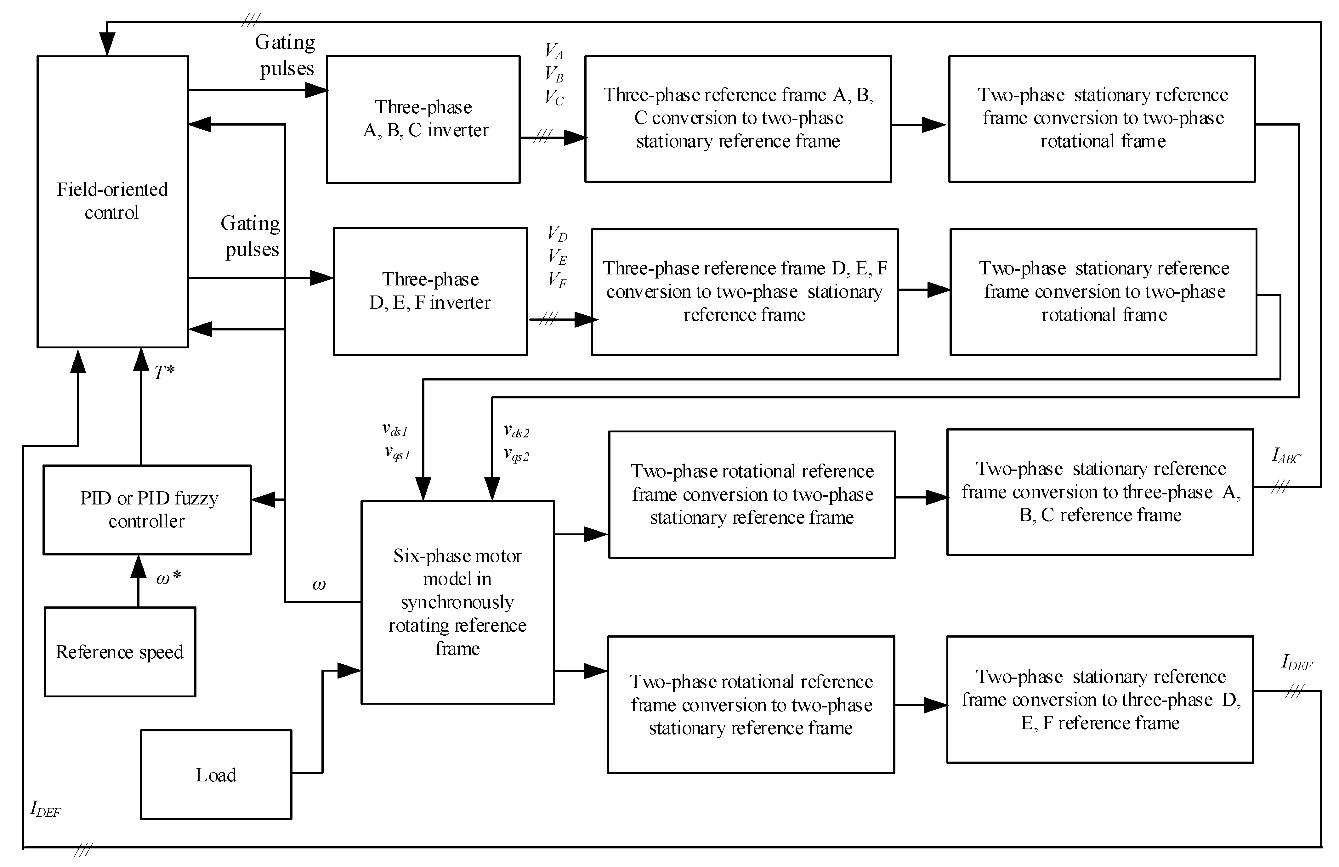
2.1. The Basics of the Simulink Model

The dynamics of multiphase electric drive can be described by nonlinear differential equations with time-varying coefficients. Due to changing mutual inductances post-rotation, mathematical descriptions of three-phase motors with a stationary three-phase reference frame are rarely used in modeling and analysis. Frequently, the conventional d-q model is used to examine induction motor performance.
The six-phase motor has six symmetrically distributed windings with shifts of 60 degrees between them. The magnetic flux is sinusoidally distributed around the stator. Therefore, the higher spatial harmonics of magnetomotive force can be neglected. Windings are connected in a star formation. The motor has a cage-type rotor. According to [21], the Clark transformation for six-phase machines can be used to replace six sinusoidal voltages with six other voltage components. Only the first two of them, α-β, take part in developing the motor’s torque; the x-y components do not cause stator–rotor coupling and do not produce torque. They do not exist at sinusoidal flux distribution around the stator. Zero components can exist if the phase number is even; however, with short-circuited cage rotor windings, the x-y and zero components do not exist.
In the rotational reference frame, d-q components stand for α-β components.
In [15], an equivalent per-phase circuit of the symmetrical six-phase machine with two winding sets is given, along with a mathematical model of the machine. The equivalent circuit’s stator has two direct current supply voltages, v q s 1 and v q s 2 , as well as v d s 1 and v d s 2 , in the reference frame with a d and q axis. Rotor supply voltages, v q r and v d r , are assumed to be zero for cage-type rotors. In various forms, the d-q mathematical model is used for analyzing induction motor dynamics. A rotor reference frame was employed in [5,21,22]. Stationary reference frames are also widely used in analyzing electrical machines, notably in [17,19,27]. The rotating synchronous speed reference frame is applied by the authors of [16,24,25,26] to model six-phase controlled induction drive. The Simulink models developed in any reference frame allow for analyzing control methods and transients in multiphase drive systems [16,18,24].
The Simulink libraries do not include six-phase voltage converters. The developed six-phase voltage system model shown in Figure 1 is made from two typical three-phase generators. The two generators make it possible to obtain a six-phase voltage system from two sets of three-phase voltages: A-B-C and D-E-F. Voltage set D-E-F is shifted by 60 electrical degrees relative to voltage set A-B-C. The two sets of three-phase voltages are transformed into two-phase stationary reference systems using the Clarke transformation of the six-phase voltages separately applied to each set of three-phase voltages.
The equations of the six-phase motor in the synchronously rotating reference frame are expressed as voltages v q s 1 and v d s 1 , as well as v q s 2 and v d s 2 , which are applied across two sets of stator windings and voltages across one common rotor winding, v q r and v d r :
v q s 1 = R s i q s 1 + s ψ q s 1 + ω ψ d s 1 ; v d s 1 = R s i d s 1 + s ψ d s 1 ω ψ q s 1 ; v q s 2 = R s i q s 2 + s ψ q s 2 + ω ψ d s 2 ; v d s 2 = R s i d s 2 + s ψ d s 2 ω ψ q s 2 ; v q r = R r i q r + s ψ q r + ω 0 ω r ψ d r ; v d r = R r i d r + s ψ d r ω 0 ω r ψ q r ,
The flux linkages aligned with the direct and quadrature axis are calculated according to the equivalent circuit [27], which assumes that the stator contains two similar sets of three-phase windings with a leakage inductance, L l 1 , and mutual leakage inductance between two stator winding sets, L l m . An equivalent circuit stator has two direct current supply voltages, v q s 1 and v q s 2 , in a reference frame with d and q axes. The rotor is supplied with voltages, v d s 1 and   v d s 2 , which are assumed to be zero for a cage-type rotor. R 1 stands for stator resistance and R 2 for rotor resistance referred to stator. L m is the magnetizing inductance, and L l m is the mutual leakage inductance between two stator windings, while L l s is the stator leakage inductance, and L l r is the rotor leakage inductance. The stator q axis current components, i q s 1 and i q s 2 , and stator d axis current components, i d s 1 and i d s 2   , as well as the rotor currents on the q and d axis, i q r and i d r , can be entered into the equations to calculate flux linkages:
ψ q s 1 = L l s + L l m + L m i q s 1 + L l m + L m i q s 2 + L m i q r ; ψ d s 1 = L l s + L l m + L m i d s 1 + L l m + L m i d s 2 + L m i d r ; ψ q s 2 = L l s + L l m + L m i q s 2 + L l m + L m i q s 1 + L m i q r ; ψ d s 2 = L l s + L l m + L m i d s 2 + L l m + L m i d s 1 + L m i d r ; ψ q r = L l r + L m i q r + L m i q s 1 + i q s 2 ; ψ d r = L l r + L m i d r + L m i d s 1 + i d s 2
ψ q s 1 , ψ q s 2 stand for the stator q axis flux linkage, ψ d s 1 , ψ d s 2 stand for the stator d axis flux linkage, and ψ q r and ψ d r are rotor q and d axis flux linkages, respectively.
The motor provides electromagnetic torque, which can be expressed as follows:
T e = 6 2 P 2 L m L l r ψ d r i q s 1 + i q s 2 ψ q r i d s 1 + i d s 2 ,
where P is the number of poles.
The electric drive movement is described by the following equation:
d ω r d t = 1 J r T e T L ,
where ω r is the motor rotational velocity, J r is the rotor inertia, T e is the electromagnetic torque, and T L is the load torque.
The analysis of the dynamics of polyphase motors applies all the general assumptions of electrical machines. A three-phase machine transformation from a stationary three-phase reference frame, A-B-C, to a two-phase stationary reference frame, d s   q s , and a synchronously rotating reference frame, d q , is described in [28], where the stator voltage v A axis is aligned with the v q axis. The transformations are carried out in this way. If the d s q s axes of a stationary three-phase machine are oriented at an angle of θ, the voltages, v d s s and v q s s , can be expressed as follows:
v q s 1 s v d s 1 s v 0 s 1 s = 2 3 cos θ cos ( θ 12 0 ) cos ( θ + 12 0 ) sin θ sin ( θ 12 0 ) sin ( θ + 12 0 ) 0.5 0.5 0.5 v A v B v C ,
where v 0 s s is a zero component. For a balanced, three-phase voltage system, v 0 s s = 0 .
The angle θ is generally assumed to be zero.
The inverse transformation of (5) can be performed as follows:
v A = v q s 1 s ; v B = 1 2 v q s 1 s 3 2 v d s 1 s ; v C = 1 2 v q s 1 s + 3 2 v d s 1 s .
Synchronously rotating d q axes with respect to d s q s axes at a synchronous speed ω e forms an angle θ e = ω e t . The voltages in the d s q s axes are transformed into d q axes in the following way:
v q s 1 = v q s 1 s cos θ e v d s 1 s sin θ e ; v d s 1 = v q s 1 s sin θ e + v d s 1 s cos θ e .
According to reference frame transformation theory, a set of three-phase voltages, v D , v E , and v F , shifted 120° apart, starting with the phase voltage v D and lagging the voltage v A by 60°, and could be transformed into a stationary reference frame as follows:
v q s 2 s v d s 2 s v 0 s 2 s = 2 3 cos ( θ 6 0 ) cos ( θ 18 0 ) cos ( θ 30 0 ) sin ( θ 6 0 ) sin ( θ 18 0 ) sin ( θ 30 0 ) 0.5 0.5 0.5 v D v E v F
Equation (8) can be written as follows:
v q s 2 s v d s 2 s v 0 s s = 1 2 1 1 2 3 2 0 3 2 0.5 0.5 0.5 v D v E v F
Then, the inverse transform becomes
v D = 1 2 v q s 2 s 3 2 v d s 2 s ; v E = v q s 2 s ; v F = 1 2 v q s 2 s + 3 2 v d s 2 s .
According to Equation (9), sinusoidal variables in the D E F reference frame take the shape of sinusoidal quantities in a rectangular reference frame, v q s 2 s and v d s 2 s .
Voltages v q s 2 s and v d s 2 s can be transformed into the synchronously rotating reference frame as follows:
v q s 2 = v q s 2 s cos θ e v d s 2 s sin θ e ; v d s 2 = v q s 2 s sin θ e + v d s 2 s cos θ e .
Voltages from the rotating reference frame can be resolved into a stationary reference frame in this way:
v q s 2 s = v q s 2 cos θ e + v d s 2 sin θ e ; v d s 2 s = v q s 2 sin θ e + v d s 2 cos θ e .
Two transformations for two three-phase voltage sets, v A v B v C and v D v E v F , where voltages are shifted by 120 electrical degrees in each set as considered above, facilitate the transformation of voltages into a stationary rectangular reference frame with Equations (5) and (9). The variables from the rectangular stationary reference frame are transformed into a synchronously rotating reference frame using Equations (7) and (11). A Simulink model of a six-phase motor formulated from Equations (1)–(4) is given in [28].
The block diagram in Figure 1 shows a developed Simulink model of a six-phase drive with indirect field-oriented control and PID and PID fuzzy controllers.
PID or PID fuzzy controllers allow for a comparison of the reference and motor speeds (Figure 1). The controller elaborates the reference torque signal. A field-oriented block comprises two inner blocks, comparing currents IA, IB, IC and ID, IE, IF with the current calculated from the reference torque, T*. Each inner block produces gating pulses for three-phase converters, which are tuned to generate three-phase voltage sets, VA, VB, VC and VD, VE, VF, where voltage VD lags voltage VA by 60 electrical degrees. The next blocks transform three-phase voltages into two-phase voltages in the stationary reference frame, and the last conversion transforms the two-phase stationary frame into a rotational reference frame, forming two voltages, vds1 and vqs1, vds2 and vqs2, which are entered as input signals into the six-phase motor model. The output currents of the motor are ids1, iqs1 and ids2, iqs2 in the two-phase rotational reference frame. Each pair of currents is converted into a two-phase stationary reference frame, i q s 1 s ,   i d s 1 s , and i q s 2 s , i d s 2 s , using an equation similar to Equation (12), where voltages should be replaced by currents with corresponding subscripts and superscripts. They are then transformed into two sets of three-phase currents, IA, IB, IC and ID, IE, IF, which are used as feedback for two field-oriented control blocks. This generates gating pulses according to the given torque reference signal and defines the torque-producing currents, i q s 1 s and i q s 2 s , comparing these with the calculated motor currents, converting them into a two-phase stationary reference frame. This produces gating pulses, changing the voltages and, finally, the motor speed, which follows the speed reference.
A fuzzy controller is one of the intelligent controllers suitable for systems with no mathematical model. Fuzzy control is nonlinear. The six-phase motor d-q model in the rotating reference frame, based on the equivalent motor circuit with two stator windings and a single rotor winding, is a nonlinear complex model, which can have variable parameters and load disturbances.
The fuzzy controller can control similar systems. The operation of a fuzzy logic controller is based on sets. Such a controller consists of a fuzzification block, the knowledge base, and the inference engine, as shown in Figure 2. The fuzzification block of a fuzzy controller transforms analogue inputs into fuzzy sets [29]. Seven linguistic variables related to the membership functions are used to describe these sets: PB (positive big), PM (positive medium), PS (positive small), ZE (zero), NS (negative small), NM (negative medium), and NB (negative big). The center of gravity method is used to calculate the output signal of fuzzy logic controllers.
The designed system controller is based on the error, the integral error, and the error derivative as inputs. Each input represents several linguistic variables defining the possible state of the output. The knowledge base consists of the membership functions and the fuzzy rules, which are acquired via knowledge of the system operation according to the provided speed reference or load application. These values can be calculated or measured. Membership functions comprise two types of functions: triangular inside the set and trapezoidal at its ends. Trapezoidal functions correspond to NB (negative big) and PB (positive big) linguistic variables. Triangular functions stand for NM, NS, ZE, PS, and PM linguistic variables. If the error is significant, a large output signal will be produced to force the controlled output to follow the setpoint value; a small signal will be produced when approaching the setpoint or at small deviation from it (see Table 1). Operating in this way, better control results are obtained.
The knowledge base defines the rules in the IF-THEN rule base, relating the input and output variables. Comparison fuzzy controllers, employing 25 or 49 rules, show a slight advantage in terms of control [24,26]. The designed controller includes forty-nine rules, which were developed according to Table 1.
To make decisions, the inference engine, which is based upon the input fuzzy sets, uses the IF-THEN rules in the knowledge base. These rules were implemented using the MATLAB Fuzzy toolbox.
The knowledge base uses forty-nine IF-THEN rules and output membership functions to produce the fuzzy output. The defuzzification process converts the fuzzy output variables into a crisp output. The designed fuzzy controller was based on the per-unit membership functions, which are presented in Figure 3. Scaling factors were used to match the error and its derivative and integral to the per-unit membership functions.

2.2. Model of Indirect Rotor Flux Orientation

According to [30], in the case of indirect field-oriented control, the rotor flux vector is aligned with the axis, d, of the rotating d q reference frame. Two reference frames, both stationary d s q s and rotating at synchronous speed d q , are translated by an angle θ e between them.
The angle between two reference frames, θ e , constantly changes with the rotor rotation and is used to transform rotating variables into a stationary two-phase reference frame. The rotor flux, Ψ ¯ r , is aligned with the axis, d; it is therefore projected onto the d axis, Ψ r d = Ψ ¯ r and Ψ r q = 0 . Then, the torque, delivered by an induction motor, is calculated as follows:
T e = 6 2 p 2 L m L r Ψ r d i s q
The current i s q in the stationary reference frame is calculated from the chosen speed reference, ω r , and the current, i s d , from a given flux reference, Ψ r , rotating at a synchronous speed ω 0 .
θ = ω 0 d t .
The angle of Ψ r denotes the reference frame orientation angle and is calculated as follows:
θ e = ω 0 d t = ω s l * + ω r d t = i s q * τ r i s d * + P 2 ω m d t .
where ω m is measured as the mechanical speed of the motor, τ r = L r R r is the rotor time constant, i s d is the reference current calculated from the reference flux, Ψ r , and ω s l * = i s q * τ r i s d * is the slip speed.
Closed-loop implementation under constant flux conditions requires calculating the reference current, i s d , from the reference flux, Ψ r :
i s d = i m r d = Ψ r d L m
Since i s q is proportional to T e , current i s q is calculated as follows:
i s q = T e k t i s d ,
where
k t = 3 2 P 2 L m 2 L r .  
The vector control Simulink model of a six-phase motor enters the Simulink model of a total six-phase drive, as shown in Figure 1.
The small power motor parameters were experimentally measured by performing locked rotor and no-load tests. The results of these are given in Table 2.

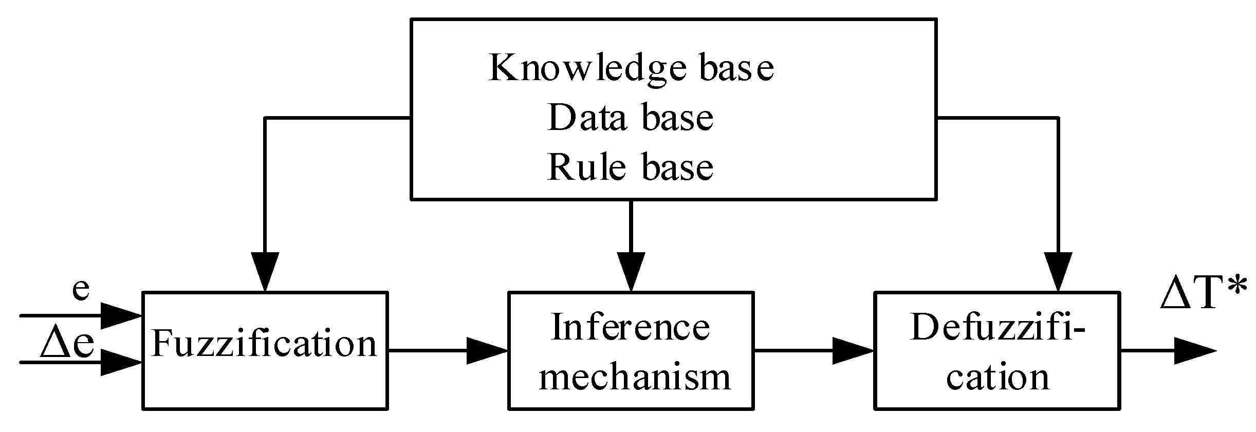
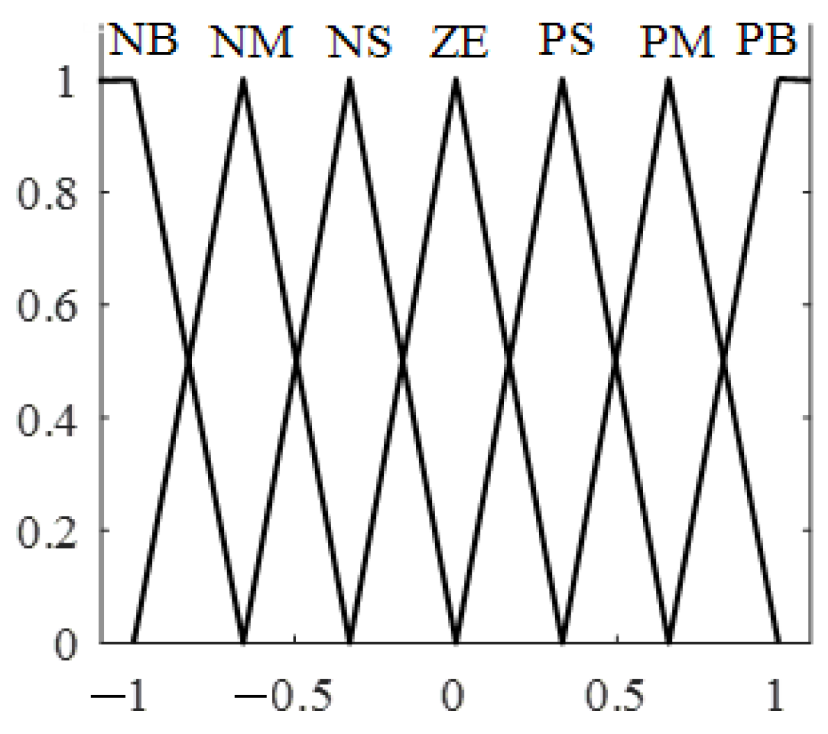
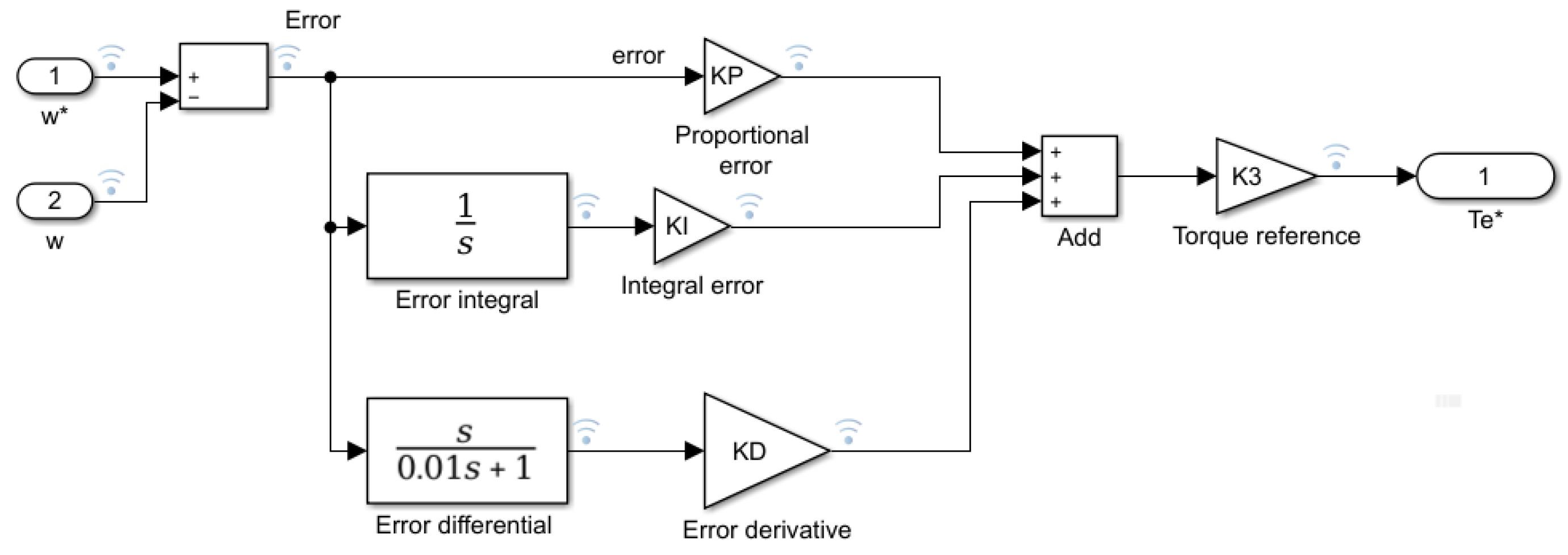
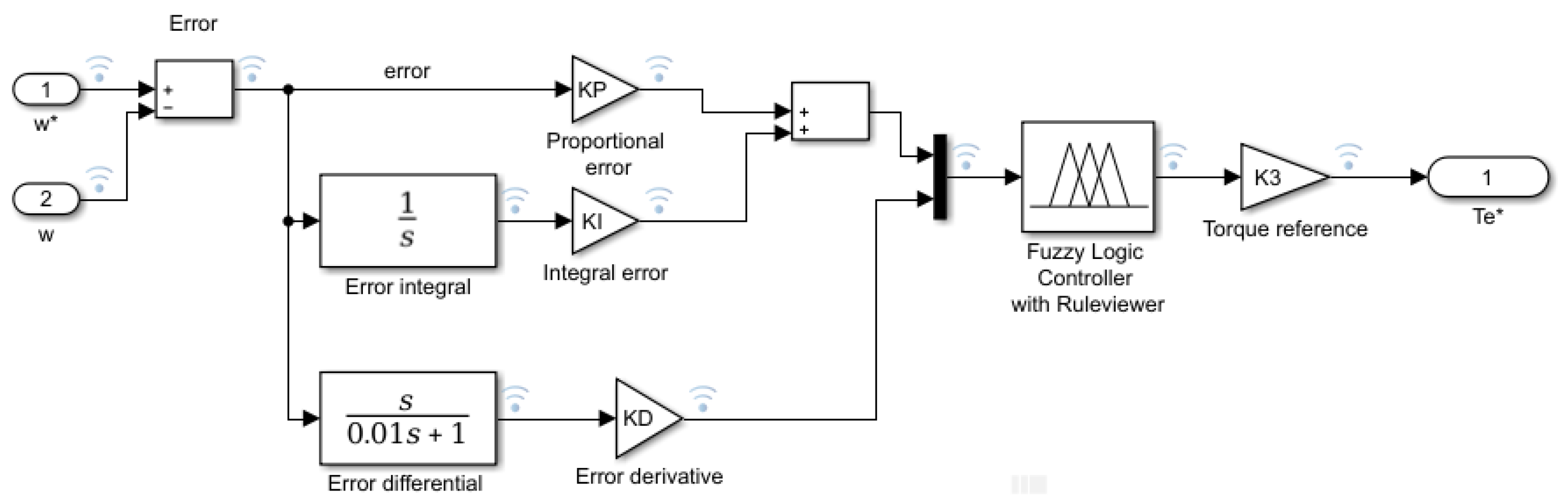
2.3. PID and PID Fuzzy Controllers

A PID controller consists of parallel connection proportional, integral, and derivative controllers, as shown in Figure 4.
KP, PI, and KD are tunable gains. K3 defines the final value of the output signal, or the “Torque reference”, required for the control system.
The PID tuning methods were based on the experience gained by tuning PI and PD fuzzy controllers [25,26]. All controller gains were tuned manually. Adjustable gains were chosen to obtain the best step response system specifications: KP = 1; KI = 0.01; KD = 0.001; and K3 = 25.
A model of a PID fuzzy controller is shown in Figure 5. It consists of the same PID controller as a fuzzy controller. A fuzzy controller has two inputs: the sum of proportional and integral errors composes one input, while the error derivative forms the other. The integral error usually has a small value [25,26]. A high-value integral error causes oscillations in the system, so it could be integrated with the proportional error constituting one fuzzy controller input.
A fuzzy logic controller is designed with per-unit membership functions for inputs and outputs [26]. It comprises forty-nine rules to calculate the output according to two input signals.
Both PID and PID fuzzy controllers operate well with the same adjustment for experience gains: KP = 1; KI = 0.01; KD = 0.001; and K3 =25.

3. Simulation Results of System with PID and PID Fuzzy Controllers

3.1. Simulation Results of System with PID Controller

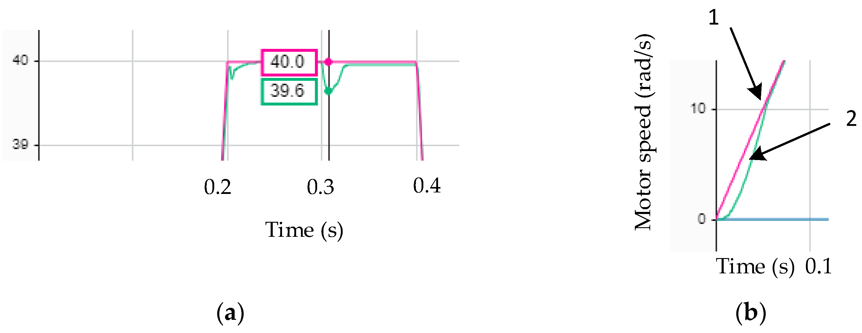
3.1.1. Step Response of System with PID Controller

The step response of a field-oriented six-phase drive control system with a PID controller is shown in Figure 6a.
Figure 6a indicates the motor speed approaching the set-up speed of forty rad/s without overshoot. The settling time is 0.12 s. The load, applied at 0.3 s, shows a negligible time increase in the motor-produced load. With load, the speed reduces by 0.5%, and this is cancelled out over 0.01 s.
The torque reference signal is formed from the sum of the proportional, differential, and integral errors. The sum is amplified by K3 = 25. The reference torque becomes an unreachable value of 1100 Nm.
Figure 6b shows the motor phase current with step response. At the start, the greatest current value reaches 2.8 A. When the motor speed reaches a steady state, the phase current reduces up to 0.3 A; with the load applied at t = 0.3 s, it again rises to 1.8 A. After removing the load, the current returns to its steady-state no-load value.

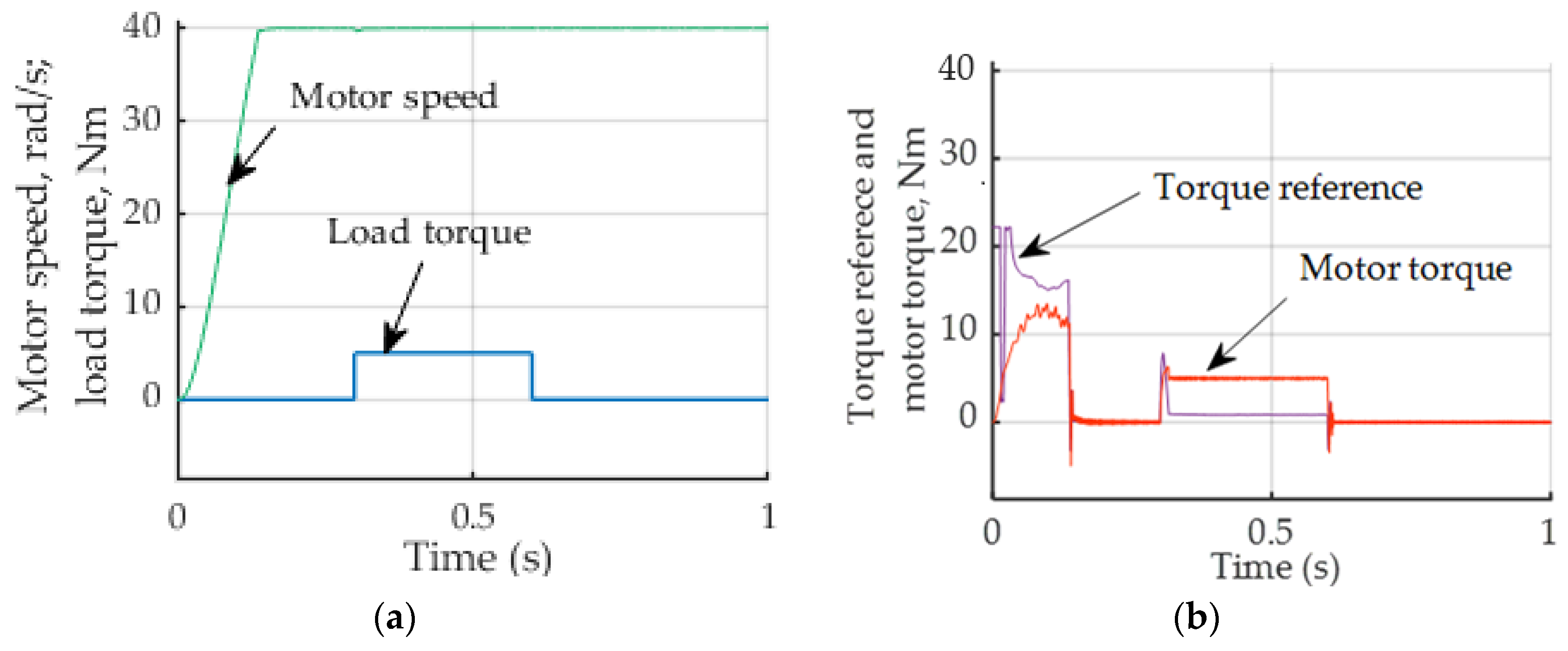
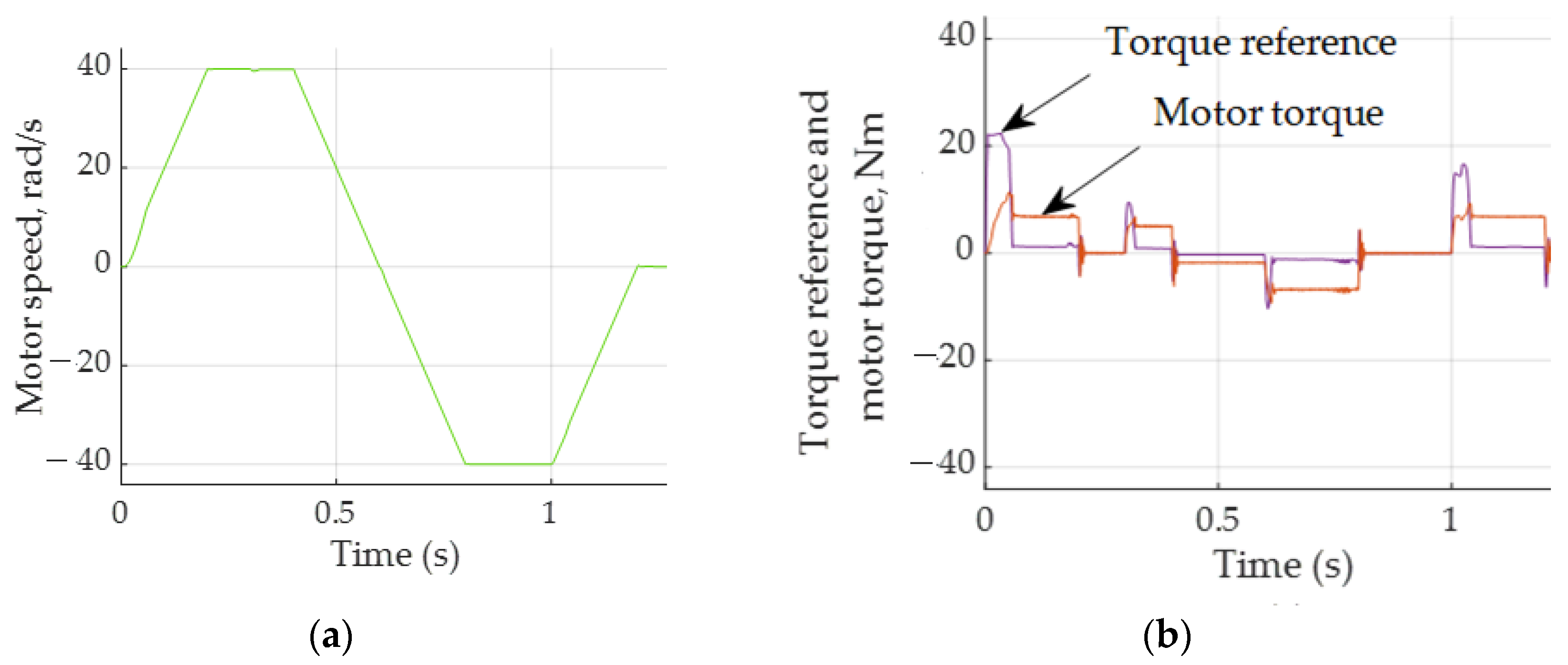
3.1.2. Simulation Results of System with PID Controller and Provided Reference Speed

Figure 7 shows the speed reference, load torque as input signal, and motor speed response.
Most motors must follow a speed reference: acceleration, steady state, deceleration after reverse acceleration, steady state, and deceleration to zero speed, as shown in Figure 7a.
When the motor speed reaches a steady state at time t = 0.3 s, a load of 5 Nm is applied.
Figure 7b shows the actual motor speed. Applying a load instantly increases the motor torque up to 5 Nm.
Figure 8 indicates that, with deceleration, the motor torque becomes negative. It then changes direction to provide a reference speed.
At the start, the PID controller establishes a great torque reference, equal to 68 Nm; this reference should be achieved in real equipment.
Figure 9a presents an increased view of the motor speed at load application and the difference between the speed response and actual speed at the start (Figure 9b). The motor speed is reduced by 1%, and this is removed after 0.03 s with a remaining constant steady-state error of 0.075%.
The initial speed delay lasts about 0.06 s. At this time, a small delay can be seen; nevertheless, after 0.06 s, the motor speed follows the reference speed exactly.

3.2. Simulation Results with PID Fuzzy Controller

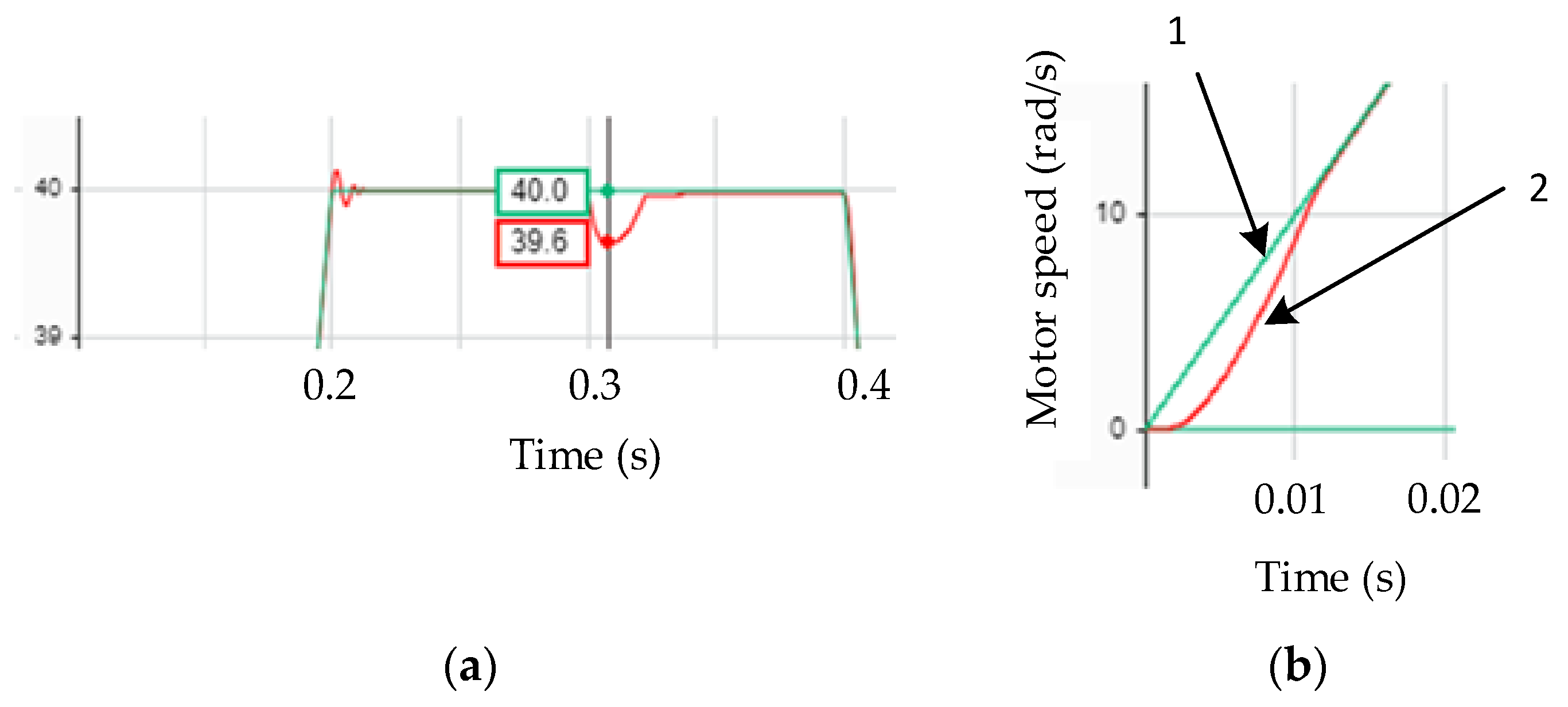
3.2.1. Step Response of System with PID Fuzzy Controller

The step response of a vector-controlled six-phase drive with a PID fuzzy controller is shown in Figure 10a. Without overshoot, the motor speed reaches a steady-state value. After applying a 5 Nm load, the motor speed reduces by 1%. The settling time is close to 0.14 s.
Figure 10b clearly shows the nonlinear behavior of the fuzzy controller. The greatest output value of this controller is 0.86. At the start, the amplified fuzzy controller output (Figure 10b) does not exceed 22 Nm.

3.2.2. Simulation Results of System with PID Fuzzy Controller and Provided Reference Speed

The motor speed is shown in Figure 11a at the provided speed reference of the fuzzy PID controller system.
The reference torque produced by PID fuzzy controller output is amplified, developing a reference input of 22.3 Nm, which is much smaller than in the case of a PID controller, which is equal to 68 Nm (Figure 8).
Together with a fuzzy controller, a PID improves the transient specifications: in the same way, speed decreases with load but is removed more quickly. The output of a nonlinear fuzzy controller controls the motor currents in order to deliver the required torque, the maximum value of which is 11.4 Nm, which is close to that (11.5 Nm) without a fuzzy controller.
Figure 12a presents an increased view of the motor speed at load application. This reduces by 1% and, after a brief time (0.012 s), is removed. The difference between the speed reference and actual speed at the start lasts 0.012 s (Figure 12b).
According to the given simulation results and previous research, such as references [24,25,26], and by rearranging some models to only operate in the classical controller mode, the simulation results were tabulated. Table 3 presents the step response specification results. Systems with classical controllers, PD, PI, and PI-D, yield neither steady-state error nor overshoot; the same is true with PD, PI, PI-D, and PID fuzzy controllers. Systems with PID controllers yield steady-state errors of 0.075. The shortest settling time can be achieved with PID and PID fuzzy controllers.
The greatest and the smallest load-related errors yield systems with classical PI-D and PI, PID controllers, respectively.
Great torque reference values can be achieved for classical controllers, but for all types of fuzzy controllers, due to their nonlinearity, quite realistic values can be obtained.
The greatest motor torque produced by controlled motors with all types of controllers differs slightly.
Using classical controllers, Table 4 presents the performance specifications of systems with defined speed references for both classical and fuzzy controllers. All systems do not exhibit any overshoot. A steady-state error can be noticed in the system with a PID fuzzy controller, while the settling time is the same. The maximal error due to load appears with PD and PI fuzzy controllers, and this is equal to 1%. The PI-D and PI controllers, however, have smaller errors of 0.87%. Nevertheless, classical PI, PD, and PI-D controllers provide smaller load errors.
The torque reference values for classical PD, PI, PI-D, and PID controllers are unrealistic at over 1000.

4. Discussions

In this study, we researched the problem of discovering and applying the correct mathematical description of six-phase motors, facilitating the development of a complex, controlled six-phase drive model, including controlled frequency converters and indirect vector control. We applied built-in Simulink and Simscape blocks and designed PID and PID fuzzy controllers.
The six-phase voltage was generated by two controlled converters, producing two sets of three-phase voltage shifted by sixty electrical degrees.
Fuzzy controllers, based on forty-nine linguistic rules with per-unit membership functions, were designed and implemented in our model. PID and PID fuzzy controllers were designed. Heuristic PID tuning methods, based on the experience gained by tuning PI and PD fuzzy controllers, were employed.
A Simulink model for a six-phase drive with two PID and PID fuzzy controllers was developed and simulated.
Both systems indicated good step response and performance specifications. The load-related slowing was the same for both systems; it did not exceed 0.95% and 0.87%, respectively, and was removed quickly. With the PID controller, after 0.03 s, the remaining constant steady-state error was 0.075% (Table 4), while the PID fuzzy controller removed this decrease in 0.012 s and had no steady-state errors.
The PID fuzzy controller more exactly followed the reference speed; after 0.012 s, there was no error between the reference and actual speeds. The PID controller operates more slowly, and the error disappeared after 0.06 s.
The amplified reference torque produced by the PID fuzzy controller had a realistic value of 22 Nm; that with the PID controller reached 68 Nm. Nevertheless, the motor could not produce torque greater than 13.7 Nm in all cases. This value corresponds to the calculated breakdown torque.
A comparison of the step response in the systems with classical PD, PI, PI-D, and PID controllers indicated that these systems have neither steady-state error nor overshoot; the same was true with PD, PI, PI-D, and PID fuzzy controllers. The system with a PID controller yielded a small 0.075% steady-state error. The shortest settling times can be achieved with the PID and PID fuzzy controllers.
Systems with classical PD, PI, PI-D, and PID controllers have limitations: in real systems, a torque reference of 1000-1100 (Nm) can hardly be achieved. Therefore, these controllers should be replaced by those supplied by fuzzy controllers. Alternatively, adaptive controllers should be designed and applied.
In fuzzy controller development, future work will be devoted to tuning each proportional, integral, and derivative gain for classical PID and modified PI-D and I-PD controllers in line with the model. Adaptive controllers should also be designed and the experimental base enhanced.

5. Conclusions

In this study, our analysis and application of the correct mathematical description of a six-phase motor allowed us to develop a complex, controlled six-phase drive model, including controlled frequency converters and indirect vector control. Using built-in Simulink and Simscape blocks, we designed PID and PID fuzzy controllers.
The fuzzy controller, based on Mamdani membership functions and forty-nine rules, was designed and supplied with a PID controller.
The developed Simulink model of a six-phase motor drive, controlled by PID and PID fuzzy controllers or its individual parts, can be adapted to control real-time systems.
Both controllers provide good transient response specifications, which could help in developing robust systems.
The step response at the hardest input—the step reference—was simulated. We compared our results with those of systems containing classical PD, PI, PI-D, and PID controllers and those with PD, PI, PI-D, and PID fuzzy controllers.
A comparison of the step response across these systems indicated that they have neither steady-state error nor overshoot. The system with a PID controller yielded a small 0.075% steady-state error. The shortest settling time of 0.14 s was achieved with PID and PID fuzzy controllers.
The PID fuzzy controller exhibits a more exact tracking of the speed reference at the beginning of the process.

Author Contributions

Conceptualization, R.R. and B.M.; methodology, R.R.; software, R.R.; validation, R.R. and B.M.; formal analysis, B.M.; investigation, R.R.; resources, B.M.; datacuration, B.M.; writing—original draft preparation, R.R.; writing—review and editing, R.R.; visualization, R.R.; supervision, R.R. project administration, R.R.; funding acquisition, B.M. All authors have read and agreed to the published version of the manuscript.

Funding

This research received no external funding.

Data Availability Statement

Conflicts of Interest

The authors declare no conflicts of interest.

References

  1. Levi, E. Multiphase electric machines for variable-speed applications. IEEE Trans. Ind. Electron. 2008, 55, 1893–1909. [Google Scholar] [CrossRef]
  2. Brazhnikov, A.V.; Belozerov, I.R. Prospects for the use of Multiphase Inverter-fed Asynchronous Drives in the Field of Traction Systems of Railway Vehicles. Int. J. Railw. 2012, 5, 38–47. [Google Scholar] [CrossRef]
  3. Bugade, V. Multiphase Induction Motor Drive for Energy and Electrical Transportation Applications. Int. J. Res. Appl. Sci. Eng. Technol. 2018, 6, 166–174. [Google Scholar] [CrossRef]
  4. Akpama, E.J. Six Phase Induction Motor Modelling for Submarine Application. J. Electr. Electron. Eng. 2018, 13, 61–66. [Google Scholar] [CrossRef]
  5. Abdelwanis, M.I.; Selim, F. A sensorless six-phase induction motor driving a centrifugal pump system. In Proceedings of the 2017 19th International Middle-East Power Systems Conference, MEPCON 2017, Cairo, Egypt, 19–21 December 2017; pp. 242–247. [Google Scholar] [CrossRef]
  6. Rao, Y.L.N. A novel electric vehicle control—Electronic differential—Strategy using five phase induction motor. Int. J. Creat. Res. Thoughts 2018, 32, 153–159. [Google Scholar]
  7. Salem, A.; Narimani, M. A Review on Multiphase Drives for Automotive Traction Applications. IEEE Trans. Transp. Electrif. 2019, 5, 1329. [Google Scholar] [CrossRef]
  8. Listwan, J.; Oleszczyszyn, P. Analysis of the Drive of the Electric Vehicle with Six-Phase Induction Motor. Power Electron. Drives 2023, 8, 252–274. [Google Scholar] [CrossRef]
  9. Cao, W.; Mecrow, B.C.; Atkinson, G.J.; Bennett, J.W.; Atkinson, D.J. Overview of electric motor technologies used for more electric aircraft (MEA). IEEE Trans. Ind. Electron. 2012, 59, 3523–3531. [Google Scholar] [CrossRef]
  10. Xie, J.; Shi, W.; Shi, Y. Research on Fault Diagnosis of Six-Phase Propulsion Motor Drive Inverter for Marine Electric Propulsion System Based on Res-BiLSTM. Machines 2022, 10, 736. [Google Scholar] [CrossRef]
  11. Mesai-Ahmed, H.; Jlassi, I.; Marques Cardoso, A.J.; Bentaallah, A. Multiple Open-Circuit Faults Diagnosis in Six-Phase Induction Motor Drives Using Stator Current Analysis. IEEE Trans. Power Electron. 2022, 37, 7275–7285. [Google Scholar] [CrossRef]
  12. Antunes, H.R.P.; Fonseca, D.S.B.; Cardoso, A.J.M. Modeling of Symmetrical Six-Phase Induction Machines Under Stator Faults. IEEE Trans. Ind. Appl. 2023, 59, 3232–3242. [Google Scholar] [CrossRef]
  13. Singh, G.K.; Iqbal, A. Modeling and analysis of six-phase synchronous motor under fault condition. Chin. J. Electr. Eng. 2017, 3, 62–75. [Google Scholar] [CrossRef]
  14. Venter, P.; Jimoh, A.A.; Munda, J.L. Realization of a ‘3 & 6 phase’ induction machine. In Proceedings of the 2012 20th International Conference on Electrical Machines, ICEM 2012, Marseille, France, 2–5 September 2012; pp. 447–453. [Google Scholar] [CrossRef]
  15. Renukadevi, G.; Rajambal, K. Generalized model of multi-phase induction motor drive using matlab/Simulink. In Proceedings of the 2011 IEEE PES International Conference on Innovative Smart Grid Technologies-India, ISGT India 2011, Kollam, India, 1–3 December 2011; pp. 114–119. [Google Scholar] [CrossRef]
  16. Levi, E.; Bojoi, R.; Profumo, F.; Toliyat, H.A.; Williamson, S. Multiphase induction motor drives—A technology status review. IET Electr. Power Appl. 2007, 1, 489–516. [Google Scholar] [CrossRef]
  17. Mandal, S. Performance Analysis of Six-Phase Induction Motor. Int. J. Eng. Res. Technol. 2015, 4, 589–593. [Google Scholar]
  18. Nabi, H.P.; Dadashi, P.; Shoulaie, A. A novel structure for vector control of a symmetrical six-phase induction machine with three current sensors. In Proceedings of the 2011 10th International Conference on Environment and Electrical Engineering, EEEIC.EU 2011, Rome, Italy, 8–11 May 2011; Volume 1, pp. 23–29. [Google Scholar] [CrossRef]
  19. Aher, K.S.; Thosar, A.G. Modeling and Simulation of Five Phase Induction Motor using MATLAB/Simulink. Int. J. Eng. Res. Appl. 2016, 6, 1–8. [Google Scholar]
  20. Gregor, R.; Barrero, F.; Toral, S.; Durán, M. Realization of an asynchronous six-phase induction motor drive test-rig. Renew. Energy Power Qual. J. 2008, 1, 101–105. [Google Scholar] [CrossRef]
  21. Zhao, Y.; Collins, E. Fuzzy PI control design for an industrial weigh belt feeder. IEEE Trans. Fuzzy Syst. 2003, 11, 311–319. [Google Scholar] [CrossRef]
  22. Akpama, E.J.; Anih, L.U. Modelling and Simulation of Multiphase Induction Machine. Int. J. Eng. Innov. Res. 2015, 4, 2277–5668. [Google Scholar]
  23. Vukosavic, S.; Jones, M.; Levi, E.; Varga, J. Rotor flux-oriented control of a symmetrical six-phase induction machine. Electr. Power Syst. Res. 2005, 75, 142–152. [Google Scholar] [CrossRef]
  24. Rinkevičiene, R.; Mitkienė, B.; Udris, D. Modelling and Comparison PID Fuzzy Controllers for Six-phase Drive. In Proceedings of the 2023 IEEE Open Conference of Electrical, Electronic and Information Sciences (eStream), Vilnius, Lithuania, 27 April 2023; pp. 1–5. [Google Scholar] [CrossRef]
  25. Rinkeviciene, R.; Mitkiene, B.; Udris, D. Modelling of Six-Phase Electric Drive with PI and PD Fuzzy Controllers. In Proceedings of the 2021 IEEE Open Conference of Electrical, Electronic and Information Sciences, eStream 2021, Vilnius, Lithuania, 22 April 2021. [Google Scholar]
  26. Rinkeviciene, R.; Mitkiene, B.; Udris, D. Design and Comparison of Fuzzy Controllers for Six-phase Drive. In Proceedings of the 2020 IEEE Open Conference of Electrical, Electronic and Information Sciences, eStream 2020, Vilnius, Lithuania, 30 April 2020; pp. 1–5. [Google Scholar] [CrossRef]
  27. Wogi, L.; Ayana, T.; Morawiec, M.; Jąderko, A. A Comparative Study of Fuzzy SMC with Adaptive Fuzzy PID for Sensorless Speed Control of Six-Phase Induction Motor. Energies 2022, 15, 8183. [Google Scholar] [CrossRef]
  28. Kundrotas, B.; Lisauskas, S.; Rinkeviciene, R. Model of multiphase induction motor. Elektron. Ir Elektrotechnika 2011, 111, 111–114. [Google Scholar] [CrossRef]
  29. Passino, K.M.; Yurkovich, S. Fuzzy control. In The Control Systems Handbook: Control System Advanced Methods, 2nd ed.; Taylor & Francis Ltd.: London, UK, 2010. [Google Scholar] [CrossRef]
  30. Bose, B.K. Modern Power Engineering and Electric Drives; Prentice Hall: Hoboken, NJ, USA, 2002. [Google Scholar]
Figure 1. Block diagram of six-phase drive with PID and PID fuzzy controllers.
Wevj 15 00164 g001
Figure 2. Structure of fuzzy controller.
Wevj 15 00164 g002
Figure 3. Input and output per-unit membership functions.
Wevj 15 00164 g003
Figure 4. Model of PID controller.
Wevj 15 00164 g004
Figure 5. Model of PID fuzzy controller.
Wevj 15 00164 g005
Figure 6. Motor variables: (a) motor speed and load torque; (b) phase current.
Wevj 15 00164 g006
Figure 7. (a): Speed reference (1) and load torque (2); (b): motor speed.
Wevj 15 00164 g007
Figure 8. Torque reference and produced motor torque at defined speed reference.
Wevj 15 00164 g008
Figure 9. (a) Increased view of motor speed at load application, red color is for speed reference, green for actual speed; (b) difference between speed reference (1) and actual speed (2) at start.
Wevj 15 00164 g009
Figure 10. Step response simulation results of system with PID fuzzy controller: (a) motor speed and load torque; (b) torque reference and torque delivered by motor.
Wevj 15 00164 g010
Figure 11. (a) Motor speed; (b) torque reference and motor speed.
Wevj 15 00164 g011
Figure 12. (a) Increased view of motor speed at load application, green color is for speed reference, and red for actual speed; (b) difference between speed reference (1) and actual speed (2) at start.
Wevj 15 00164 g012
Table 1. Linguistic variables of the fuzzy controller.
Error
NBNMNSZEPSPMPB
Derived errorPBZEPSPMPBPBPBPB
PMNSZEPSPMPBPBPB
PSNMNSZEPSPMPBPB
ZENBNMNSZEPSPMPB
NSNBNBNMNSZEPSPM
NMNBNBNBNMNSZEPS
NBNBNBNBNBNMNSZE
Table 2. Motor parameters.
ParameterNotationDataUnits
Magnetizing inductance L m 0.295H
Stator leakage inductance L l s 0.07H
Stator mutual inductance L l m 0.07H
Rotor leakage inductance L l r 0.115H
Stator resistance R s 68
Rotor resistance R r 4.5
Motor inertiaJ0.034
Number of polesP8
Table 3. Tabulated values of step response simulation results.
Performance SpecificationsControllersFuzzy Controllers
PDPIPI-DPIDPDPIPI-DPID
Steady-state error, %00000000
Overshoot, %00. 5000000
Settling time, s0.160.140.1360.140.20.20.20.14
Maximal error due to load, %0.750.510.5110.50.75
Load, Nm55555555
Fuzzy controller output----0.890.890.890.86
Torque reference, Nm110010001100110022.322.1622.222.1
Greatest motor torque, Nm13.713.211.611.510.911.111.913
Table 4. Performance specifications with defined speed reference.
Performance SpecificationsControllersFuzzy Controllers
PDPIPI_DPIDPDPIPI-DPID
Steady-state error, %00000000.075
Overshoot, %00000000
Settling time, s0.20.20.20.20.20.20.20.2
Maximal error due to load, Nm0.750.750.750.95110.870.87
Load, Nm55555555
Fuzzy controller output----0.890.890.890.87
Torque reference, Nm7270.8686822.322.322.322.3
Greatest motor torque, Nm11.711.711.611.510.810.911.811.4
Disclaimer/Publisher’s Note: The statements, opinions and data contained in all publications are solely those of the individual author(s) and contributor(s) and not of MDPI and/or the editor(s). MDPI and/or the editor(s) disclaim responsibility for any injury to people or property resulting from any ideas, methods, instructions or products referred to in the content.

