Article

Path Tracking and Anti-Roll Control of Unmanned Mining Trucks on Mine Site Roads

1
School of Automotive and Traffic Engineering, Jiangsu University, Zhenjiang 212013, China
2
Automotive Engineering Research Institute, Jiangsu University, Zhenjiang 212013, China
*
Author to whom correspondence should be addressed.
World Electr. Veh. J. 2024, 15(4), 167; https://doi.org/10.3390/wevj15040167
Submission received: 26 March 2024 / Revised: 10 April 2024 / Accepted: 11 April 2024 / Published: 16 April 2024
(This article belongs to the Special Issue Advanced Vehicle System Dynamics and Control)

Abstract

:
Aiming to address the tracking accuracy and anti-rollover problem of the unmanned mining truck path tracking process under the complex unstructured road conditions in mining areas, a coordinated control strategy for path tracking and anti-rollover based on topology theory is proposed. Moreover, optimal equilibrium weights are assigned to path tracking control and anti-rollover control to ensure that the path tracking accuracy of the mining vehicle can be effectively improved in a safe and stable driving state. Regarding the path tracking problem, a lateral preview error model is established, and a path tracking controller is designed using LQR (linear quadratic regulator) control theory. In the design of the anti-rollover controller, the effects of understeer and trip-type rollover on the stability of the vehicle are taken into account, and the ideal transverse swing angular velocity and trip-type rollover evaluation index are introduced for controller design, which reduce the effects of the curves and roadway excitation on the mining truck and improve the rollover motion. Based on a joint simulation using Trucksim and Simulink and the construction of a hardware-in-the-loop simulation platform for verification, the single control strategy and coordinated control strategy are compared and analyzed. The final simulation results show that the tracking error, yaw velocity, and center of mass side deviation angle are optimized by 45%, 32.5%, and 20%, respectively. Therefore, the Extension theory-based coordinated controller satisfies the complex road conditions in the mining area and improves the tracking accuracy to the maximum extent while ensuring the safety and smoothness of vehicle driving and exhibiting good adaptability and robustness.

1. Introduction

In recent years, the state has attached increased importance to the construction of green mines. The National Development and Reform Commission and eight other ministries and commissions have jointly issued “Guiding Opinions on Accelerating the Intelligent Development of Coal Mines”, and the development of open-pit mines to promote the high-level and in-depth fusion of information technology and industrialization has become imperative. With the rapid development of science and technology, automatic driving technology has matured and been applied to many scenarios, one of which is the development of automatic driving in mining areas. Path planning and path tracking are the main problems to be solved regarding automatic driving in mining areas. Mining road networks may have multiple alternative paths and unsafe areas [1]. In order to plan effective detour routes around these unsafe areas, simulation-based and clustering-based optimization techniques are used [2]. This paper mainly focuses on vehicle tracking control. The question of how to ensure the accurate control of path tracking and smooth driving has become the focus and main challenge in realizing the accurate and safe tracking of the target paths of mining trucks, which has far-reaching research significance.
Lateral motion control is one of the three key issues in path tracking control and has garnered significant attention from numerous research scholars. According to the existing studies on lateral motion control, based on the adoption of different control methods, they can be classified into model-free control methods [3,4,5], linear control methods [6], and nonlinear control methods [7,8]. Among these methods, the common PID control algorithms [9,10] are hindered by the need for trial-and-error in parameter selection due to unknown or time-varying vehicle models, resulting in laborious work and suboptimal practical efficacy. The pure pursuit algorithm [11,12] does not consider the vehicle’s force conditions, and its tracking performance relies on the selection of the lookahead distance, making it difficult to obtain an optimal solution and resulting in variable tracking effectiveness. Sliding mode control [13,14] is prone to chattering due to delays, which affects vehicle stability and tracking precision when sensor signals fluctuate or actuator control is suboptimal. Model predictive control (MPC) [15,16] increases the computational burden and time consumption with the addition of model dimensions and constraints, making it challenging to tune for practical application. Linear quadratic regulator (LQR) control, on the other hand, assumes control inputs are unconstrained during the solving phase, which makes it easier to design, and it offers appreciable control effectiveness with good real-time performance. In the design of LQR control, reference [17] incorporates the road curvature of multiple preview points into the augmented state vector and constructs an enhanced linear quadratic problem, the optimal solution of which can avoid issues with significant magnitude errors. The literature [18] constructs a path tracking error model and proposes an adjustment rule based on the vehicle–road position relationship for parameter selection, which improves the adaptability of the controller. Building upon the literature, this paper employs LQR control theory as the guiding principle to investigate the path tracking controller for unmanned mining trucks.
At present, unmanned mining vehicle research mainly focuses on the improvement of tracking accuracy, while there is a lack of consideration for safe driving. Anti-rollover research focuses primarily on the issue of safe driving; researchers usually establish a rollover evaluation index to determine the rollover status of a vehicle. Regarding active anti-rollover technology for vehicles, to address the non-tripping rollover generated by the large centrifugal force when steering the vehicle and the tripping rollover caused by road excitation problems, commonly used solutions include differential braking, active steering, active suspension, and lateral stabilizers. In terms of control methods, Kailerk et al. [19] proposed a rollover warning system based on a neural network algorithm; it considered trip-type and non-trip-type rollover as external factor inputs, set risk level evaluation indexes, and validated a 1/5 vehicle model. Seongjin et al. [20] proposed a rollover prevention integrated control strategy that combined an active suspension system and differential braking and designed a robust controller characterized by linear–quadratic–static output feedback and a reduced parameter sensitivity scheme. The differential brake and the active suspension system acted as actuators to generate the sway moment and roll moment, respectively. The results showed that this control strategy significantly enhanced the vehicle’s ability to resist lateral sway. Termous et al. [21] proposed a coordinated control scheme based on active steering, differential braking, and active suspension, considering anti-roll and lateral stability control constraints; this effectively improved the safety and handling stability of the vehicle studied. Wang Chunyan et al. [22] designed an integrated controller based on active steering and active braking. An improved rollover indicator was proposed to take into account rollover prevention and the path tracking performance, and the tracking accuracy was improved to reduce the risk of rollover.
Based on the above analysis, there is a certain conflict between path tracking control and anti-rollover control in the process of vehicle tracking. The use of coordinated control can fully consider the coupling relationship between the systems, with high efficiency and flexibility, to achieve safe and stable driving while improving the tracking accuracy. Therefore, in this paper, to address the tracking accuracy and instability problems of unmanned mining trucks under the complex conditions of unstructured roads in mining areas, we design a sliding-mode steering anti-rollover controller to solve the instability problems caused by vehicle steering, a fuzzy PID active suspension controller to improve the body attitude, and an LQR path tracking controller to improve the tracking accuracy of the vehicle. We also put forward a coordinated control strategy for path tracking and anti-rollover based on the Extension theory, as well as a coordinated control strategy for the two systems under different working conditions. Moreover, a coordinated control strategy based on Extension theory is proposed for path tracking and anti-roll, which assigns weights to the two types of control under different working conditions and obtains an optimal and balanced control strategy to satisfy the complex environmental conditions. This effectively improves the path tracking accuracy and reduces the influence of the road surface state on the vehicle system.

2. Establishment of the Model and Rollover Evaluation Index

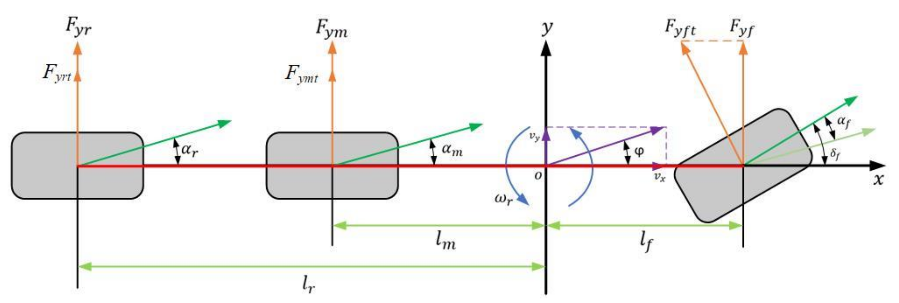
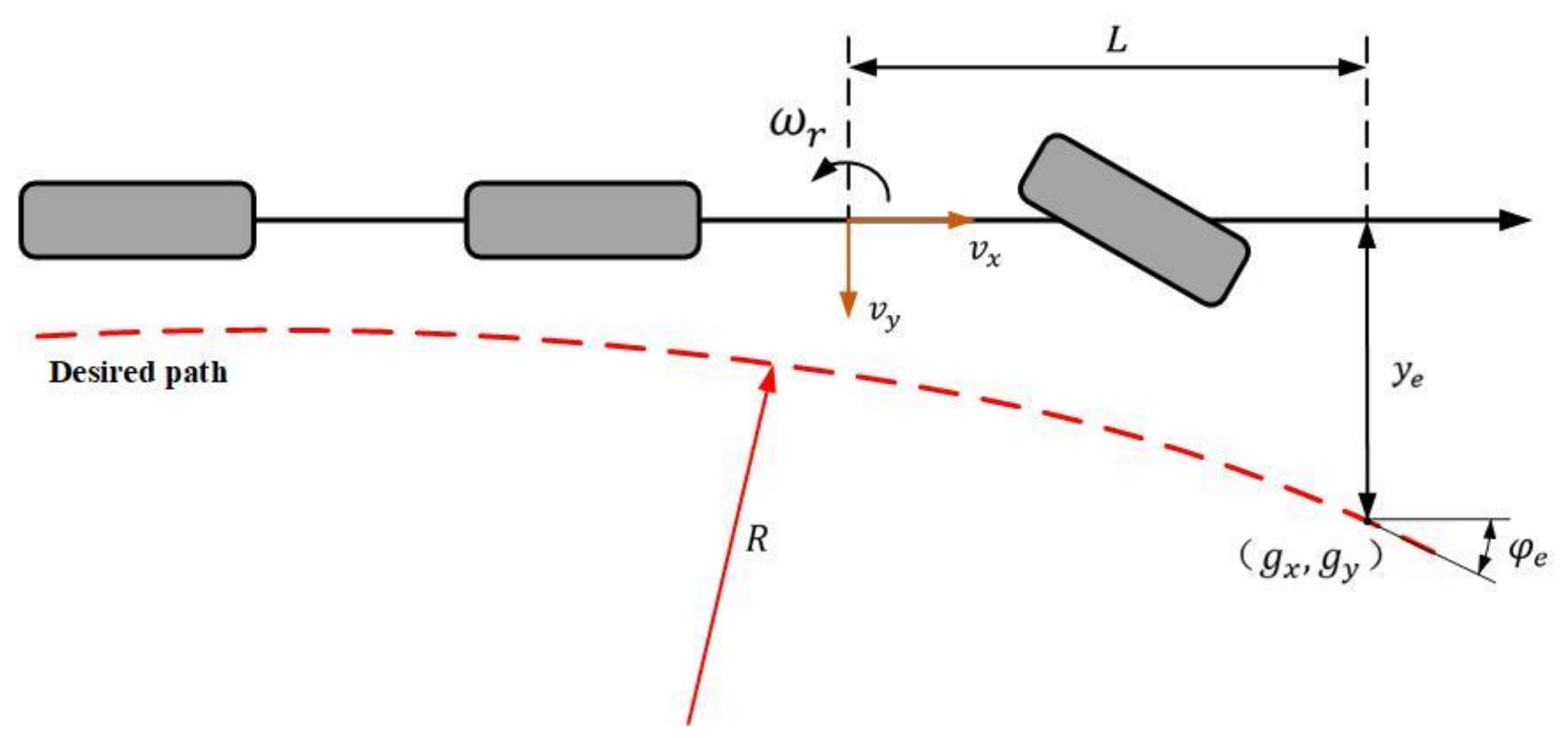
2.1. Tri-Axial Mining Truck Path following the Preview Error Model

We model a three-axle mining truck based on a two-axle vehicle model. As shown in Figure 1, the body coordinate system is established according to the mining truck; the dot is the center of mass o of the vehicle; the x-axis is along the longitudinal axis of the body; the y-axis is perpendicular to the direction of the longitudinal axis, that is, transverse to the body; and the z-axis satisfies the right-hand rule and is perpendicular to the xoy plane and upward.
As shown in Figure 1, the force analysis is carried out according to Newton’s second law of motion, and the kinetic equations are established for the mining truck in the lateral and yaw directions as follows:
m v ˙ y = m v x ω r + F y f + F y m + F y r I z ω ˙ r = l f F y f l m F y m l r F y r
where vy is the lateral speed of the mining truck; vx is the longitudinal speed of the mining truck; ω r is the yaw velocity of the mining truck; Fyf, Fym, and Fyr are the lateral forces of the tires on the front, middle, and rear axles of the mining truck, respectively; m is the mass of the entire vehicle; Iz is the moment of inertia of the mining truck around the vertical; ω ˙ r is the yaw acceleration of the mining truck; and lf, lm, and lr are the distances of the front, middle, and rear wheels of the mining truck from its center of mass, respectively.
The force analysis of the mining truck tires shows that the external force on each wheel is as follows:
F y f = n f F y f t c o s δ f F y m = n m F y m t F y r = n r F y r t
where nf is the number of front tires of the mining truck, Fyft is the tire lateral force of the individual front wheels of the mining truck, nm is the number of mid-wheel tires of the mining truck, Fymt is the tire lateral force of the individual mid-wheels of the mining truck, nr is the number of rear wheels of the mining truck, Fyrt is the tire lateral force of the individual rear wheels of the mining truck, and δ f is the front wheel steering angle.
During the driving process of mining trucks, the tires are subjected to lateral forces, and they produce lateral deflection angles. Considering that, in the linear region of the tire, the tire lateral deflection force and the lateral deflection angle are approximately proportional, the force in the y-axis direction of the tire can be expressed as follows:
F y f t = C f α f F y m t = C m α m F y r t = C r α r
where Cf denotes the front wheel equivalent lateral deflection stiffness, Cm denotes the middle wheel equivalent lateral deflection stiffness, and Cr denotes the rear wheel equivalent lateral deflection stiffness.
The front wheel side deflection α f , the middle wheel side deflection α m , and the rear wheel side deflection α r are denoted, respectively, as follows:
α f = v y + l f v φ v x δ f α m = v y l m v φ v x α r = v y l r v φ v x
Moreover, the kinematic equation of the mining truck can be expressed as follows:
X ˙ = v x c o s φ v y s i n φ Y ˙ = v x s i n φ + v y c o s φ
where X is the horizontal coordinate of the mining vehicle in the geodetic coordinate system, Y is the vertical coordinate of the mining vehicle in the geodetic coordinate system, and φ is the angle between the body and the geodetic coordinate axis.
Coupling Equations (1)–(5) are finally obtained as the kinetic model, as follows:
X ˙ = A X + B u
Among them,
X ˙ = v ˙ y ω ˙ r ,
A = 2 C f + 4 C m + 4 C r m v x 2 C f l f 4 C m l m 4 C r l r m v x v x 2 C f l f 4 C m l m 4 C r l r I z v x 2 C f l f 2 + 4 C m l m 2 + 4 C r l r 2 I z v x ,
B = 2 C f m 2 C f l f I z , u = δ f .
The path tracking error model is a comprehensive error model that combines the preview error model with the lateral dynamics model. The key influencing factors of the path tracking accuracy are the lateral error and heading error, so it is necessary to establish an error kinematic model with the lateral error and heading error relative to the desired path as state variables. As shown in Figure 2, the preview kinematic model is represented during vehicle travel.
The lateral preview error model can be represented, according to the literature [23], as follows:
φ ˙ e = v x k φ ˙ d e s y ˙ e = L ω r + v y + v x φ e
where φ e is the directional deviation at the preview point (gx, gy), k is the curvature of the road at the preview point, ye is the lateral deviation at the preview point, ω r is the yaw velocity of the vehicle, vy is the lateral velocity, and L is the preview distance.
The following equation can be obtained by substituting Equation (6) into the differential equation of the lateral dynamics of a three-axle mining vehicle and rewriting it in the form of a state space equation as follows:
e ˙ r r = A 1 e r r + B 1 U + C 1 G
In the equation:
A 1 = 0 1 0 0 0 a 22 a 23 a 24 0 0 0 1 0 a 42 a 43 a 44
a 22 = 2 C f + 4 C m + 4 C r m v x a 23 = 2 C f + 4 C m + 4 C r m a 24 = 2 C f + 4 C m + 4 C r m v x a 42 = 2 C f l f 4 C m l m 4 C r l r I z v x a 43 = 2 C f l f 4 C m l m 4 C r l r I z a 44 = 2 C f l f 2 + 4 C m l m 2 + 4 C r l r 2 I z v x
e r r = y e y ˙ e φ e φ ˙ e ,   B 1 = 0 2 C f m 0 2 C f l f I Z ,
C 1 = 0 2 C f l f 4 C m l m 4 C r l r m v x v x 0 2 C f l f 2 + 4 C m l m 2 + 4 C r l r 2 I z v x
U = δ f ,   G = φ ˙ d e s .

2.2. Road Surface Elevation Input Model

In the closed and complex environment of an open pit mining area, we not only should consider the variable attachment coefficient but also need to introduce the road surface disturbance input for impact analysis. Mining trucks traveling on complex and rugged road surfaces are often subject to discrete impacts such as bumps or pits, especially when the vehicle is steering and driving. The unilateral wheel disturbance impacts will greatly reduce the vehicle’s rollover stability, so it is necessary to analyze the impact of the road bumps on the stability of the vehicle. The following road bump impact model is established as follows:
Z r = h sin ( π v t / L ) t 0 t t 0 + L / v 0
In the equation, h denotes the height of the bump, L represents the width of the bump, v represents the vehicle speed, and t0 indicates the duration of the wheel’s contact with the impacted road surface.
Meanwhile, in order to further reflect the actual driving environment of unmanned mining trucks, the pavement spatial spectral density is established as the pavement elevation input. According to the pavement power spectral density specified by the International Organization for Standardization [24], the fitting expression is as follows:
G q ( n ) = G q ( n 0 ) ( n n 0 ) W
where Gq(n0) denotes the pavement unevenness coefficient; W is the frequency index, which is taken as 2 in this paper; n is the spatial frequency; and n0 denotes the reference spatial frequency.
When the speed of the vehicle is constant, the relationship between the time frequency and the spatial frequency is as follows:
f = v n
By combining Equations (10) and (11) and differentiating the resultant equation, we derive the power spectral density of the road surface speed.
G ˙ q ( f ) = 4 π 2 n 0 2 v G q ( n 0 )
The magnitude of the pavement velocity power spectral density is a constant k. The representation of the pavement input model in the time domain can be built using white noise w(t) with the following equation:
Z r ( t ) = k w ( t ) d t
The following equation can be obtained through the further derivation of Equation (13) and its substitution into Equation (12):
Z ˙ r ( t ) = 2 π n 0 G q ( n 0 ) v w ( t )
In order to more realistically reflect the state of the pavement in the mining area, the lower cutoff time frequency f0 is introduced into Equation (14), which can be used to obtain the filtered white noise time-domain pavement elevation input model [25]:
Z ˙ r ( t ) = 2 π f 0 Z r ( t ) + 2 π n 0 G q ( n 0 ) v w ( t )
where Z r ( t ) is the random pavement excitation displacement and Z ˙ r ( t ) is the random pavement excitation velocity.

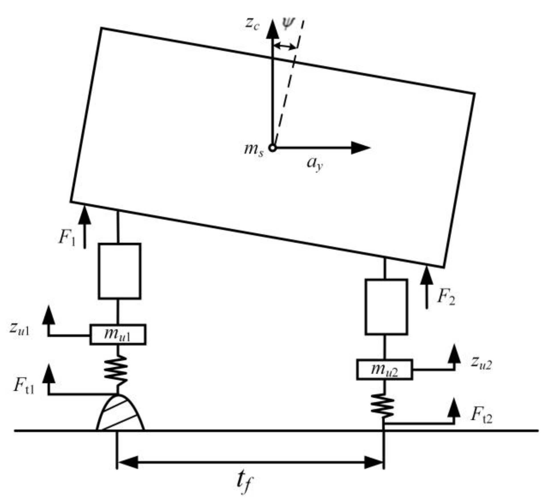
2.3. Calculation of the Trip-Induced Rollover Evaluation Index

In order to accurately determine the vehicle’s motion state in real time, a rollover evaluation index based on the dynamic driving parameters of the vehicle is constructed. In general, vehicle rollover is categorized into trip-type rollover and non-trip-type rollover [26]. The former is caused by external inputs that lead to vehicle rollover, while the latter is caused by excessive lateral acceleration when the vehicle turns. Since mining trucks need to cope with potholes and rugged road conditions, the construction of a trip-type rollover index is more in line with the analysis of the mining road environment. There is a time interval between the contact of the front axle wheels and that of the middle and rear axle wheels with the same section of road surface, and the vertical movement information of the front axle wheels can more accurately reflect the discrete impact of the road surface. Therefore, this paper utilizes one-third of the whole model of the three-axle vehicle to establish the trip-type rollover index, as shown in Figure 3.
If the direction of the suspension force remains perpendicular to the spring-mounted vehicle body, the roll motion equation should be as follows:
I x ψ ¨ = t f 2 ( F 2 F 1 ) + m s h a y cos ψ + m s h g sin ψ
The vertical motion equation for the spring-loaded mass is as follows:
F 1 + F 2 = m s z ¨ c
The vertical motion equation for the unsprung mass is as follows:
m u 1 z ¨ u 1 + F 1 = F t 1
m u 2 z ¨ u 2 + F 2 = F t 2
In the equation, Ix represents the moment of inertia of the sprung mass about the roll center; ψ denotes the body roll angle; tf is the track width of the wheels; F1 and F2 are the vertical forces of the left and right suspension, respectively; ms is the sprung mass; and h is the vertical distance from the center of gravity of the sprung mass to the roll center. ay represents the lateral acceleration; g denotes the acceleration due to gravity; z ¨ c is the vertical acceleration of the sprung mass; mu1 and mu2 are the unsprung masses on the left and right sides, respectively; z ¨ u 1 and z ¨ u 2 represent the vertical accelerations of the left and right wheels, respectively; and Ft1 and Ft2 are the tire forces of the left and right wheels, respectively.
Based on the formula for lateral load transfer ratio, substituting Equations (16), (18), and (19) and assuming mu1 = mu2 = mu, the conversion yields the trip-type rollover index as follows:
R I = m u ( z ¨ u 1 z ¨ u 2 ) m u ( z ¨ u 1 + z ¨ u 2 ) + m s z ¨ c + m g 2 t f ( I x ψ ¨ m s h a y cos ψ m s h g sin ψ ) m u ( z ¨ u 1 + z ¨ u 2 ) + m s z ¨ c + m g

3. Path Tracking and Anti-Roll Coordinated Controller Design

During the operation of unmanned mining trucks on unstructured roads, the lateral path tracking controller and the anti-rollover controller have their respective optimization objectives and are interrelated through coupling. To ensure safe and stable driving in complex road environments while effectively enhancing the vehicle’s path tracking accuracy, separate designs were implemented for the anti-rollover steering controller, active suspension controller, path tracking controller, and an integrated coordinating controller. Based on the theory of extension, a path tracking and anti-rollover coordinated controller was designed, dynamically allocating weights to overcome the limitations and insufficient adaptability resulting from a single control strategy. The control structure principle is illustrated in Figure 4.

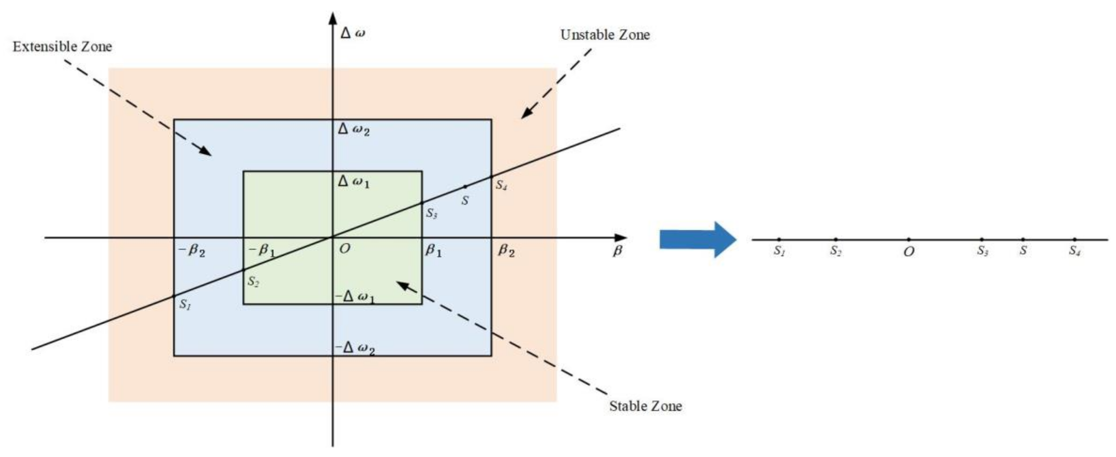
3.1. Design of a Steering Anti-Rollover Controller Based on Sliding Mode Control

In order to ensure that the vehicle still has good lateral stability when steering under different road conditions, the design of the steering anti-rollover controller must consider the influence of the yaw velocity and the center-of-mass lateral deflection angle at the same time. This paper assumes that, in the ideal state of vehicle motion, based on the two-degree-of-freedom vehicle dynamics model established in Section 2.1, we can obtain the ideal yaw velocity and center-of-mass lateral deflection angle. At this time, the yaw velocity and lateral acceleration of the vehicle are constant values and can be obtained as follows: ω ˙ r = 0 , β ˙ = 0 . Therefore, the ideal yaw rate can be obtained [27] as follows:
ω r d _ i = [ ( l f + l m ) C f C m + ( l f + l r ) C f C r ] v x δ f [ ( l f + l m ) 2 C f C m + ( l f + l r ) 2 C f C r ] ( 1 + m K 1 v x 2 )
In that, K 1 = l f C f l m C m l r C r 2 [ C f C m ( l f + l m ) 2 + C f C r ( l f + l r ) 2 ] .
Simultaneously, due to the limitations imposed by the ground adhesion limit, the desired yaw rate needs to satisfy the following condition:
ω r _ max = f μ g v x
Wherein f represents the safety factor, set at 0.85; μ denotes the road adhesion coefficient; and g stands for the acceleration due to gravity. Consequently, the final desired value for the yaw rate is obtained as follows:
ω r d = min ω r d 1 , f μ g v x · s i g n ( δ f )
In that, ω r d 1 = ω r d _ i = [ ( l f + l m ) C f C m + ( l f + l r ) C f C r ] v x δ f [ ( l f + l m ) 2 C f C m + ( l f + l r ) 2 C f C r ] ( 1 + m K 1 v x 2 ) .
Incorporating the additional yaw moment Δ M ω r into the two-degree-of-freedom model yields the following result:
β ˙ = 2 C f + 4 C m + 4 C r m v x β + ( 2 C f l f 4 C m l m 4 C r l r m v x 2 1 ) ω r 2 C f m v x δ f ω ˙ r = 2 C f l f 4 C m l m 4 C r l r I z β + 2 C f l f 2 + 4 C m l m 2 + 4 C r l r 2 I z v x ω r 2 C f l f I z δ f + Δ M ω r I z
The yaw rate tracking error and its derivative are defined as follows:
e ω r = ω r ω r d
e ˙ ω r = ω ˙ r ω ˙ r d
Simultaneously, from several sliding mode control laws, the uniform velocity approximation law is selected for its lower computational complexity, superior real-time performance, and enhanced robustness, specifically:
S ˙ ω r = K ω sgn ( S ω r )
In the formula, K ω represents the approach velocity to the sliding mode surface, which is a positive constant. By converting Equation (23) to Equation (26), the additional yaw moment can be obtained as follows:
Δ M ω r = I z ( c ω r e ˙ ω r + 2 C f l f 4 C m l m 4 C r l r I z β ˙ + 2 C f l f 2 + 4 C m l m 2 + 4 C r l r 2 I z v x ω ˙ r 2 C f l f I z δ ˙ f + Δ M ˙ ω r I z ω ¨ r d K ω sgn ( S ω r ) )

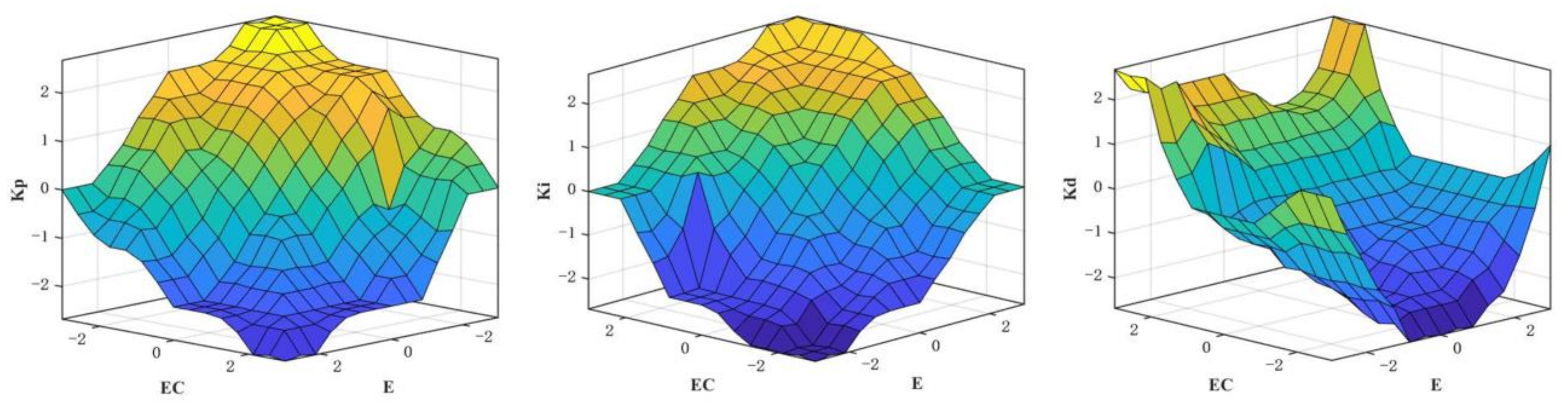
3.2. Design of an Active Suspension Controller Based on Fuzzy PID

The basic principle of the fuzzy PID controller is to regulate the increment of PID parameters based on the error e between the ideal rollover evaluation index and the rate of change of this error as inputs to the controller. In this article, the ideal rollover evaluation index RI is set to 0. The actuating forces of the vehicle’s left and right suspension systems are considered output parameters of the controller. In this paper, the values of the three parameters Kp, Ki, and Kd are obtained through the empirical trial-and-error method, being 1000, 10, and 20, respectively. The input variables of error and error rate of change, as well as the output variable for the fuzzy controller, are all described using the following seven fuzzy subsets:
e , e c = N B , N M , N S , Z E , P S , P M , P B Δ K p , Δ K i , Δ K d = N B , N M , N S , Z E , P S , P M , P B
The fuzzy domains of the input variables and output variables are set as {−3, −2, −1, 0, 1, 2, 3}. The physical domains of error e and error change rate ec are [−1, 1] and [−25, 25], respectively, and the physical domains of the three output variables are [−1800, 1800], [−12, 12], and [−150, 150]. In this paper, we achieve the purpose of order of magnitude unification by adding the scaling factor; thus, according to the above physical domains, the quantization factor can be obtained as 3 and 0.2, respectively, and the scaling factors are 600, 4, and 50, respectively. At the same time, Gaussian and triangular affiliation functions are selected to describe the input and output quantities and the corresponding fuzzy subset affiliation. The fuzzy control rules are formulated according to the relevant literature [28], as shown in Table 1, Table 2 and Table 3. Finally, the three output variables can be obtained as a function of the input variables, as shown in Figure 5.

3.3. Design of a Path Tracking Controller Based on a Linear Quadratic Regulator (LQR)

The LQR control method is adopted for the design of the coupled controller in this paper due to its ability to accommodate multiple performance indices and meet the engineering practice requirements of unmanned mining trucks in complex mine area environments. LQR optimal design theory refers to the concept in which the designed state feedback controller K minimizes the quadratic objective function J. The quadratic objective function J(u) can be represented as follows:
J ( u ) = k = 0 ( x k T Q x k + u k T R u k )
In the expression, Q and R represent the weighting matrices of the controller, with R being a positive definite matrix.
The essence of the LQR controller is to design a control law that minimizes the quadratic objective function J(u). By employing the principle of least action to solve the optimal control problem, one ultimately obtains the optimal control input u*(t):
u * t = K t e t
In the formula, K(t) = [k1, k2, k3, k4] represents the feedback gain matrix of the LQR controller.
Let the front wheel steering angle outputted by the feedforward control be denoted as δ q , then the feedback control law, upon incorporation of feedforward control, is expressed as follows:
U = K e r r + δ q
Substituting the above equation into Equation (2), when the system stabilizes, thus e ˙ r r becoming zero, it follows that:
e r r = A 1 B 1 K 1 B 1 δ q + C 1 φ ˙ d e s
By substituting A1, B1, K, and C1 into the previous expression, we obtain:
e r r = e 1 0 e 3 0
In that,
e 1 = ( 2 C f l f + 2 C f l f k 3 + 4 C m l m + 4 C r l r ) [ 2 C f δ q θ r ( 2 C f l f 4 C m l m 4 C r l r v x 2 ) / v x ] + ( 2 C f + 4 C m + 4 C r 2 C f k 3 ) [ 2 C f l f δ q θ r ( 2 C f l f 2 + 4 C m l m 2 + 4 C r l r 2 ) / v x ] / ( 8 C f C m l f k 1 + 8 C f C r l f k 1 + 8 C f C m l m k 1 + 8 C f C r l r k 1 )
e 3 = θ r ( 8 C m l m l f + 8 C r l r l f + 8 C m l m 2 + 8 C r l r 2 + 2 m v x 2 l f ) v x ( 8 C m l f + 8 C r l f + 8 C m l m + 8 C r l r )
When ye is zero, and assuming that the vehicle is traveling at a given speed, the desired path can be approximated as a curve with a constant curvature ρ . Thus, the quantity of the feedforward controller δ q can be determined as follows:
δ q = ρ [ ( 2 C f l f + 2 C f l f k 3 + 4 C m l m + 4 C r l r ) ( 2 C f l f 4 C m l m 4 C r l r m V x 2 ) + ( 2 C f + 4 C m + 4 C r 2 C f k 3 ) ( 2 C f l f 2 + 4 C m l m 2 + 4 C r l r 2 ) ] / [ 2 C f ( 2 C f l f + 2 C f l f k 3 + 4 C m l m + 4 C r l r ) + 2 C f l f ( 2 C f + 4 C m + 4 C r 2 C f k 3 ) ]

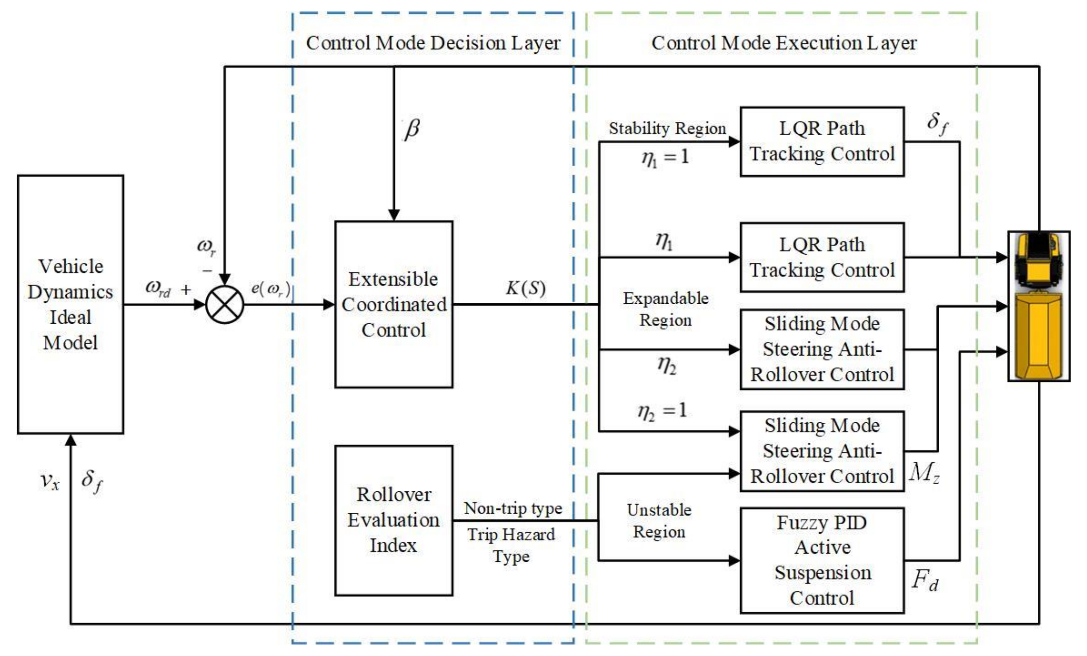
3.4. Design of a Path following and Anti-Roll Coordinated Control System

When unmanned mining trucks operate under unstructured road conditions, their stability and tracking performance exhibit certain variations. Based on anti-roll control and path tracking control strategies, this study utilizes the theory of extension to switch between different control strategies according to vehicle state and tracking accuracy, ensuring stable and precise vehicle operation. The yaw rate deviation and the lateral deviation angle of the center of mass are selected as characteristic quantities in this paper.
Taking the lateral deviation angle of the center of mass as the abscissa of the extensible set and the yaw rate error as the ordinate of the extensible set, a two-dimensional set based on the characteristic states of the vehicle is established as S ( β , Δ ω ) . Furthermore, the range of variation for the extensible set is defined as ( , + ) , and three distinct zones are generated that can map the vehicle tracking control state quantities in real-time: the stable zone, the extensible zone, and the unstable zone. For the lateral deviation angle of the center of mass, serving as the abscissa of the extensible set as β 2 , the boundary of the extensible zone can be determined based on the formula for vehicle instability conditions as follows:
β = arctan ( 0.02 μ g )
The determination of the extendable region boundary β 2 varies with changes in the road surface adhesion coefficient. On the other hand, the boundary of the stable region β 1 is ascertained based on the linear region of the yaw rate gain. By employing multiple simulations and fitting a curve to the resulting data of vehicle speed vx, the road surface adhesion coefficient μ , and the maximum front wheel steering angle δ max , a relationship amongst the three parameters can be established as follows:
δ max = 0.188 0.0036 v x + 0.125 μ
Substituting into Equation (12), the boundary of the stable region β 1 can be obtained. Meanwhile, for the extendable set, the longitudinal coordinate is the yaw rate error, which is determined using the tolerance band division method.
When ω ω r > ζ 2 ω r occurs, the vehicle is in an unstable state and is at risk of rollover.
When ζ 1 ω r < ω ω r < ζ 2 ω r , the state of the vehicle is within the extendable region, corresponding to the boundary of the extendable region Δ ω 2 = ζ 2 ω r .
When ω ω r < ζ 1 ω r , the vehicle is in a stable condition, corresponding to the stable boundary Δ ω 1 = ζ 1 ω r .
As can be obtained from Equation (8), parameters ζ 1 and ζ 2 , according to related references and empirical methods, are known to be 0.05 and 0.15, respectively. Hence, the boundary of the controllable extension set region can be determined, which varies with changes in the road surface adhesion coefficient and the tripping-type rollover index. The range of each region within this extension set is illustrated in Figure 6.
Based on the one-dimensional extension distance theory, the nearest extension distances from point S in the above figure to the stable region and the extendable region can be represented as ρ ( S , ( S 2 , S 3 ) ) and ρ ( S , ( S 1 , S 4 ) ) , respectively. Their values are as follows:
ρ ( S , ( S 2 , S 3 ) ) = S S 2               S ( , S 2 )   S S 2 S ( S 2 , 0 ) S S 3       S ( 0 , S 3 ) S S 3             S ( S 3 , + )
ρ ( S , ( S 1 , S 4 ) ) = S S 1               S ( , S 1 )   S S 1 S ( S 1 , 0 ) S S 4       S ( 0 , S 4 ) S S 4             S ( S 4 , + )
The formula for the correlation degree function is as follows:
K ( S ) = ρ ( S , ( S 1 , S 4 ) ) ρ ( S , ( S 1 , S 4 ) ) ρ ( S , ( S 2 , S 3 ) )
Concurrently, different control strategies are selected based on the varying numerical values of the correlation degree function. When K ( S ) 1 , the vehicle resides within the stable region, indicating that the current state of vehicle motion is steady, necessitating an increase in the weight of the front wheel steering angle to ensure higher tracking precision. When 0 K ( S ) < 1 , the vehicle is situated in the expandable region, signifying a tendency towards instability where solely controlling the front wheel steering angle may lead to vehicle rollover instability. This necessitates the involvement of additional yaw torque, and a redistribution of weights to ensure an improvement in vehicle body posture at bends and enhance vehicle stability. When K ( S ) < 0 , the vehicle is in the unstable region, indicating that the vehicle has reached the conditions for instability. It is necessary to increase the weight of the additional yaw torque and adopt anti-rollover control to prevent vehicle rollover.
To prevent the weight distribution from being biased towards a single aspect and to ensure greater stability in the intervention and withdrawal of the two control modes, a sigmoid function [29] is employed to redistribute the two control strategies. Consequently, the control weight for the front wheel steering angle can be represented as follows:
η 1 = 0 K ( S ) < 0 1 1 + e 11 ( K ( S ) 0.5 )           0 K ( S ) < 1 1 K ( S ) 1
The control weight for the additional yaw moment is denoted as η 2 = 1 η 1 .

4. Simulation and Results Analysis

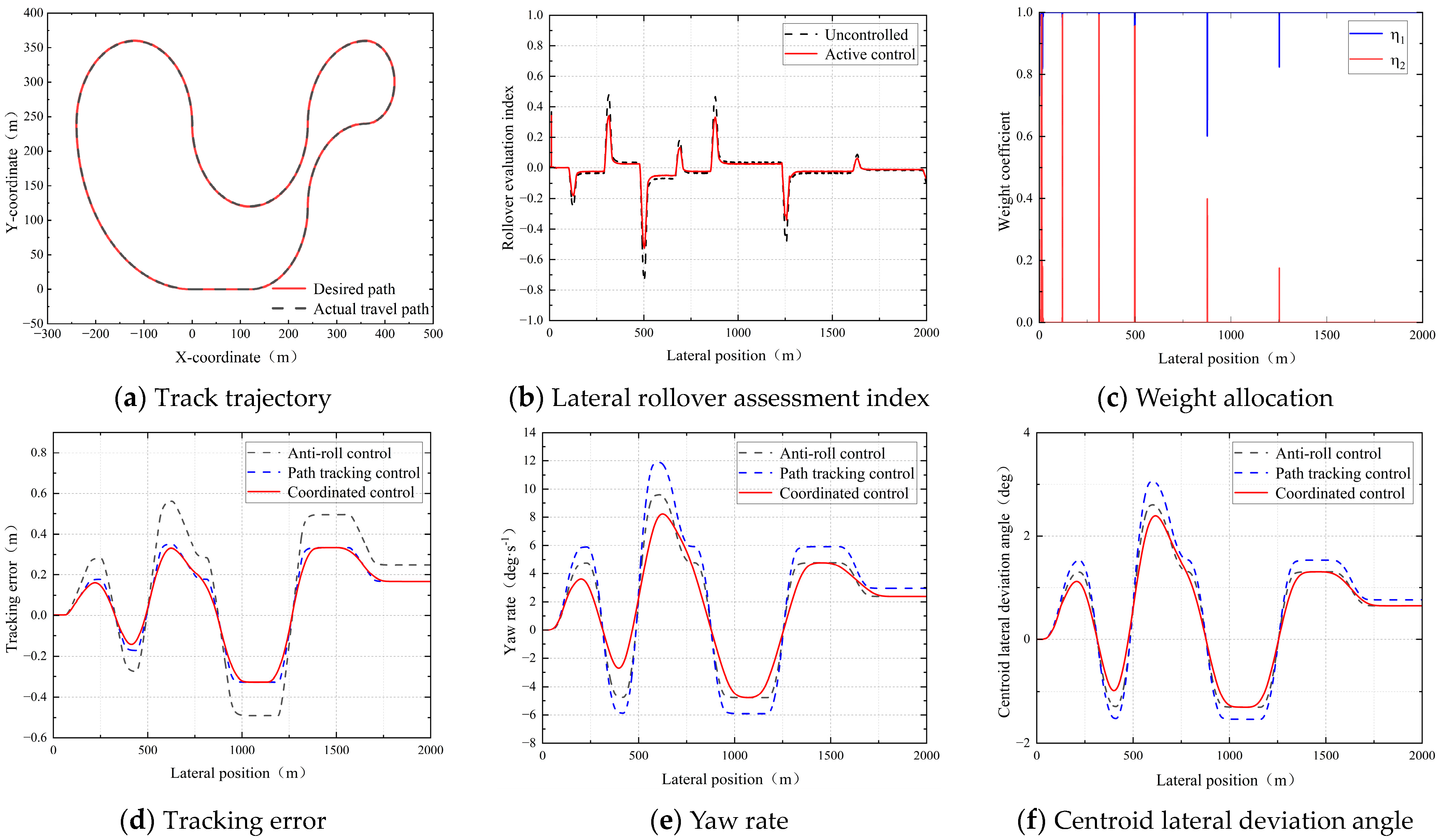
4.1. Simulation Validation under Different Working Conditions

To validate the robustness of the proposed coordinated control strategy, with respect to road excitation issues, a random road verification involving both Class C Road surfaces and road bumps is set up to test the effectiveness of the fuzzy PID active suspension controller. Regarding the vehicle instability problem caused by insufficient steering force, and to closely reflect real mine road conditions, an unstructured road with varying road curvatures and continuous curves is established. A simulation environment is constructed within Trucksim and Simulink, where relevant parameters are modified and corresponding working conditions are selected. In the simulation experiments, the vehicle’s driving speed is set to 36 km/h, the road adhesion coefficient is set to 0.85, and the primary vehicle parameters are as shown in Table 4.
Simulation Scenario I Setup: An unmanned mining truck operates on a random road surface compounded by Class C surfaces and speed bumps, with the speed bump travel length set to 0.2 m and height set to 0.1 m. The front wheel steering angle is input as a sinusoidal signal at 8 degrees. The simulation time is 10 s, and the front wheel steering angle input curve is depicted in Figure 7a.
From Figure 7b,c, it can be observed that, one second into the vehicle’s journey, the vehicle tires impact the road surface bump. The instantaneous road excitation produced by the bump causes a lateral transfer of vertical loads on the wheels. In the absence of suspension control, the vehicle’s rollover assessment indicator, RI, reaches approximately 0.56, with a body roll angle of 0.125 rad. This indicates a certain risk of vehicle rollover under the impact of the bump. However, for vehicles with suspension controlled by PID, the RI index is at 0.5, which represents a 10.7% reduction in the rollover assessment indicator compared to the uncontrolled vehicle, suggesting the control effect on the body roll angle is not pronounced, and thus, the performance of PID control is considered moderate. Simultaneously, after optimization with fuzzy PID control, the vehicle’s rollover assessment indicator is reduced to 0.38, and the body roll angle is 0.048 rad. This corresponds to a decline of 32.1% in the rollover assessment indicator and a decrease of 61.6% in body roll angle in relation to an uncontrolled vehicle. In addition, there is a significant reduction in the roll angle acceleration, indicating that the control effect surpasses that of PID control. During the 3rd to 7th second interval, where the vehicle is executing a steering maneuver, the peak rollover assessment indicators for the three vehicles are respectively 0.6, 0.54, and 0.23, while the peak body roll angles are 0.174 rad, 0.162 rad, and 0.145 rad. Under control, the rollover assessment indicators decreased by 10% and 62.7%, respectively, and the body roll angles were reduced by 6% and 16.7%, respectively. As depicted in Figure 7d, vibrations persist throughout the 10 s duration, indicating that the Class C Road surface poses a certain impact on vehicular driving safety. The optimization results of the controller are shown in Table 5.
Simulation Scenario II Setup: To better verify the rationality and effectiveness of the coordinated control strategy, a road that conforms to the complex environment of a mining area is artificially planned, as shown in Figure 8a. The road curvature changes are roughly between 0.01 and 0.02. Additionally, a road surface bump is placed at ten meters along the road, with the road input still classified as a Class C surface. Comparative analysis is conducted on the individual anti-roll control strategy, the path tracking control strategy, and the coordinated control strategy.
Figure 8b presents the graph of the rollover assessment index, from which it can be observed that the vehicle experiences an impact from the bump at 10 m, leading to instability. The rollover assessment index for the uncontrolled vehicle reaches 0.39, whereas the actively controlled vehicle exhibits a rollover assessment index of 0.34, which is an optimization of 12.8%. At 500 m, the uncontrolled vehicle presents a significant risk of instability, but under active control, its rollover assessment index is noticeably reduced, falling from −0.74 to −0.52, a 22% decrease. Figure 8c illustrates the allocation of weight between path tracking control and anti-roll control throughout the driving process. When the vehicle encounters a bump, the weight given to anti-roll control increases to improve vehicle posture. Additionally, substantial changes in weight distribution occur at 125 m, 260 m, and 500 m due to the emphasis on anti-roll control in the corners, where the yaw torque control intensity is increased to ensure smooth vehicle handling. The subsequent changes in weight allocation take place on curves with small radii, where stability is maintained while enhancing the tracking accuracy of the vehicle. From the data presented in Figure 8d–f, it can be discerned that, compared to the individual path tracking control and anti-roll control, the path tracking accuracy is optimal under the coordinated control, and the vehicle is capable of driving safely and stably. Under single control strategies, the maximum lateral displacement error reaches 0.59 m, while under the coordinated control strategy, it is reduced to 0.32 m, an improvement of 45%. In terms of yaw rate, all three control strategies exhibit significant changes at curves, with maximum values of 12 deg/s, 9.8 deg/s, and 8.1 deg/s, respectively, achieving optimizations of 32.5% and 17.3%, effectively enhancing the operational stability of the vehicle during turns. As inferred from Figure 8f, the maximum centroid lateral deviation angle under the path tracking control is 3 degrees, whereas the maximum value under coordinated control is reduced to 2.4 degrees, achieving an enhancement of 20%. Simultaneously, it is evident that the vehicle’s path tracking performance deteriorates significantly when the yaw rate and the centroid lateral deviation angle are at their peaks. Therefore, a rational allocation of weights can ensure the maximization of safe and precise driving. The optimization results of the controller are shown in Table 6.

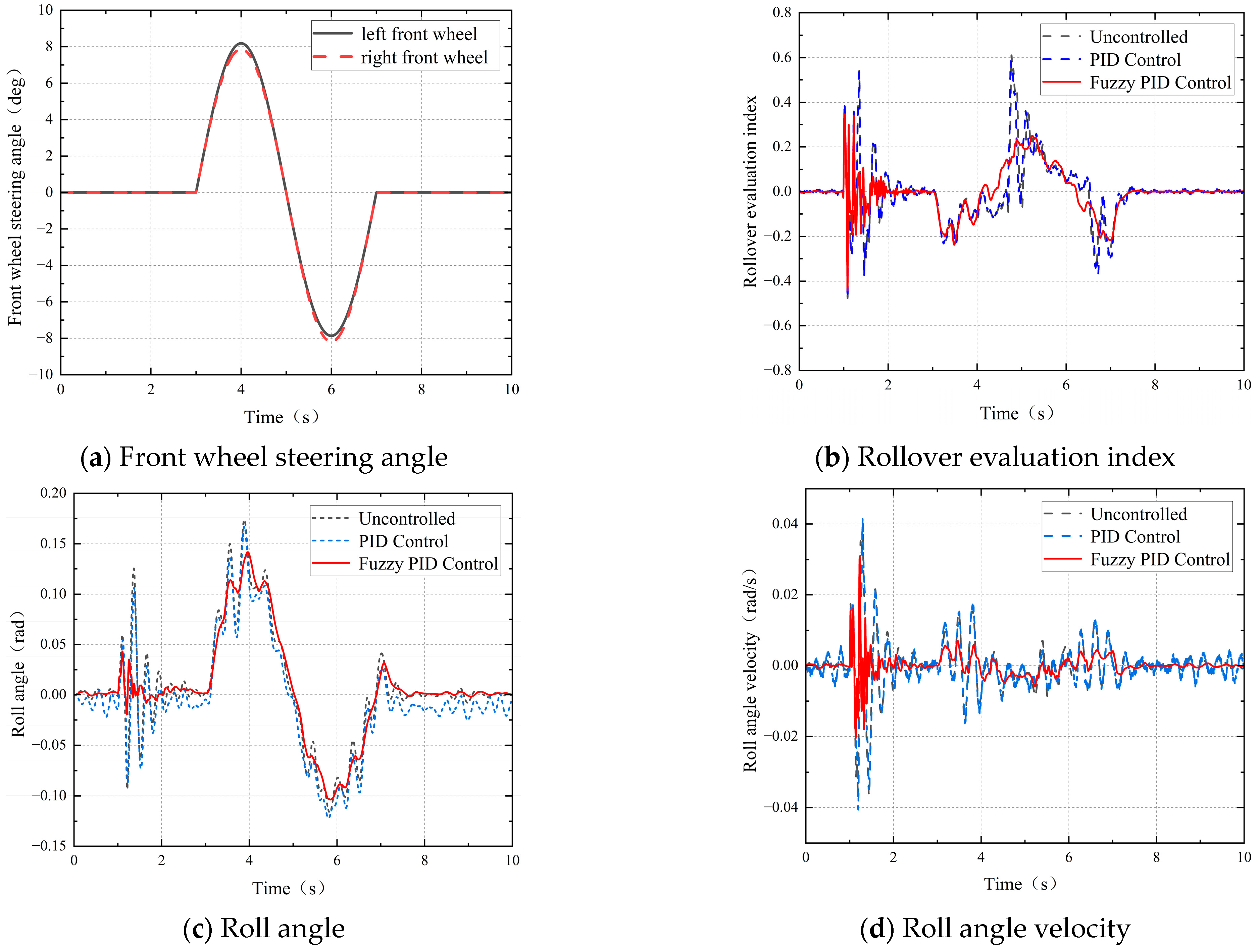
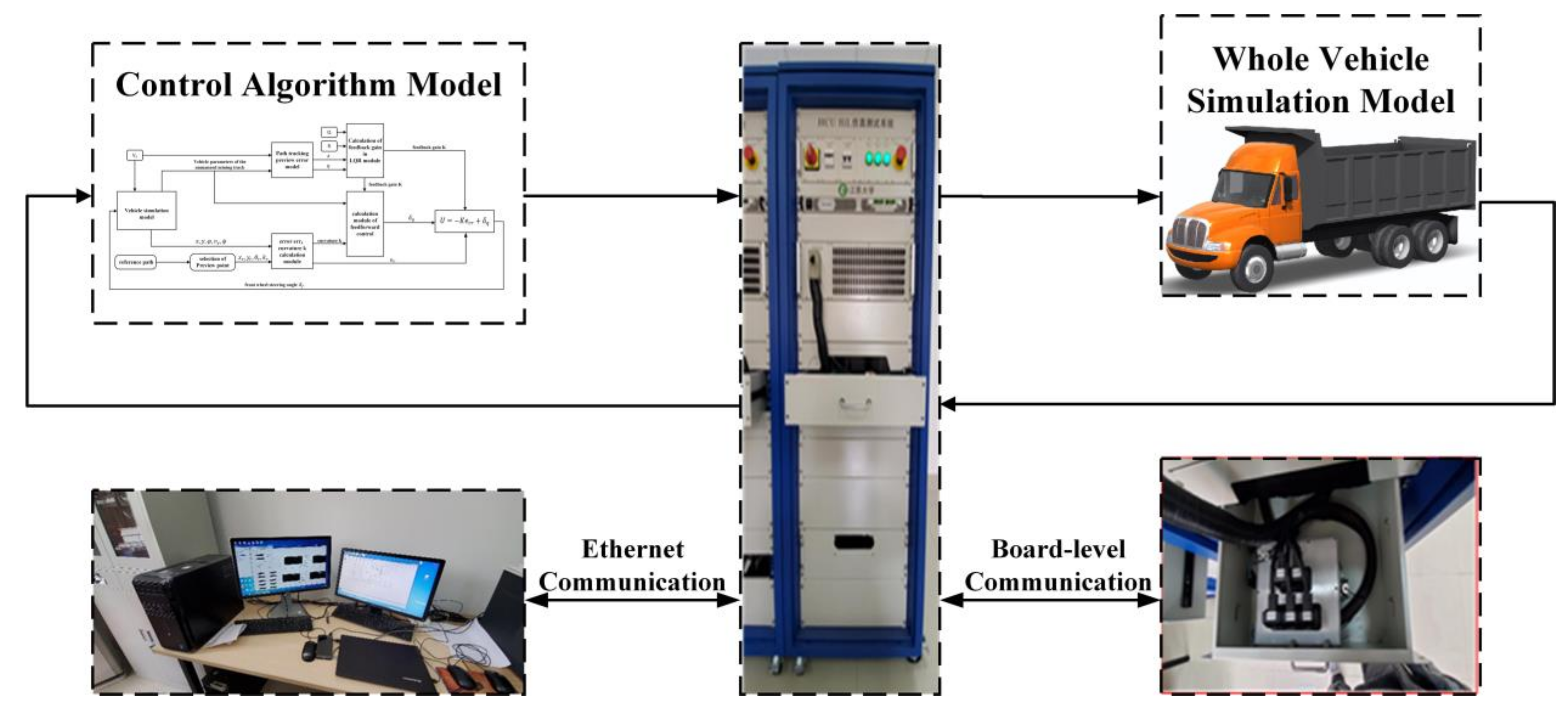
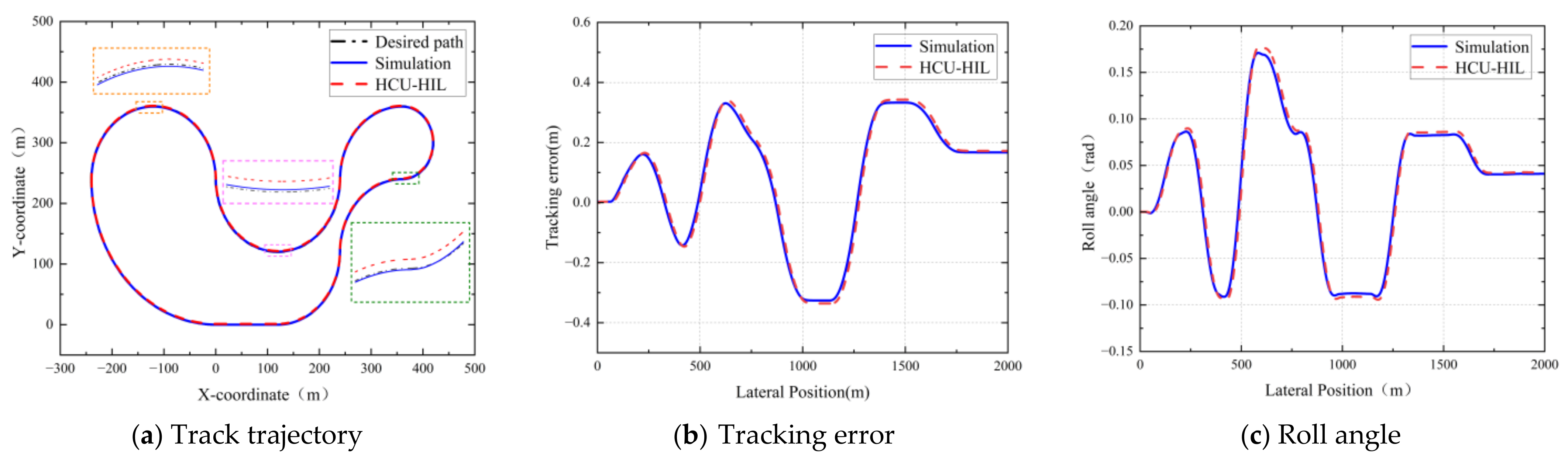
4.2. HCU-HIL Experimental Validation

In this paper, a path tracking and anti-rollover coordinated controller is designed based upon a three-axle mining truck utilized as the simulation vehicle. To further verify the effectiveness of this controller, the consideration of conducting a Hardware-in-the-Loop (HIL) simulation experiment is proposed. Figure 9 illustrates the overall scheme of the Hardware-in-the-Loop experimental setup.
As shown in Figure 9, the full vehicle model is imported into the upper computer simulation platform while concurrently undergoing a transcoding operation. Subsequently, the simulation platform conveys the real-time vehicle state data to the D2P controller for configuring the message information. After processing by the controller, the vehicular driving parameters are output back to the simulation platform. Data exchange occurs between the two entities, culminating in the realization of a comprehensive Hardware-in-the-Loop control workflow. The specific operational steps are as follows: first, the full vehicle simulation model file is imported into the NI VeriStand software; second, the control algorithm model is inputted into the D2P controller via MotoHawk (Jiangsu University, Zhenjiang 212013, China), and message information is configured; subsequently, a real-time target machine and various types of board equipment are added, such as data acquisition cards, memory cards, and CAN communication board cards; and finally, a HIL testing environment is created for the adjustment and observation of the full vehicle model as well as a series of setups, including input-output port mapping connections and parameter calibration.
The correctness of the simulation results is verified by comparing them with the outcomes from the Hardware-in-the-Loop (HIL) experiments. The vehicle travels on a Class C Road surface superimposed with bumps at a speed of 36 km/h. The comparison between the HIL experimental results and the simulation findings is illustrated in Figure 10.
From the diagram, it can be observed that in the HIL experiments, the controller can complete the trajectory tracking task under set road conditions, demonstrating good control precision. The simulation experiment results maintain a high level of consistency with the HIL experiment outcomes. However, there is a certain latency in controller performance during the HIL experiment simulations. Additionally, due to the differences between the simulated model of the tri-axial mining truck and the actual vehicle, as well as factors such as the computational speed limitations of the controller and the latency in CAN signal transmission, deviations exist between the simulation outcomes and HIL results. Nonetheless, these deviations remain within an acceptable range.

5. Conclusions

Addressing the issue of poor tracking performance and vehicle rollover susceptibility in unmanned mining trucks navigating the uneven, non-structured roadways with large turning radii typical of mining areas, a predictive error model for path tracking of a three-axle mining truck is established. Moreover, a trip-over-type rollover evaluation index is obtained through calculation. For the path tracking problem, an LQR lateral controller is designed, and for the anti-rollover issue, a sliding mode steering anti-rollover controller and a fuzzy PID active suspension controller are developed. In addition, the extensible theory is utilized to optimize the single control strategy, dynamically allocating the weights of the control variables. Finally, through Trucksim and Simulink simulations, the following research conclusions are obtained:
(1) The extensible theory-based coordinated controller, designed for unmanned mining trucks on non-structured roads in mining areas, selects operation modes according to different working conditions and dynamically allocates weights. This effectively enhances the vehicle’s driving stability and tracking accuracy on non-structured roads, demonstrating notable adaptability and robustness.
(2) Utilizing the Trucksim and Simulink simulation environments, the effectiveness of the designed extensible theory-based coordinated controller was validated, and a comparative analysis was conducted between the single control strategy and the coordinated control strategy. Simulation results indicate that extensible theory-based coordinated control not only ensures vehicular safety but also achieves higher tracking precision. It optimizes parameters such as rollover assessment index, lateral displacement error, yaw rate, and the angle of lateral deviation of the center of mass, showing improvements of 12.8%, 45%, 32.5%, and 20%, respectively. Therefore, the extensible theory-based coordinated controller meets the complex and variable road conditions of mining areas and possesses considerable adaptability and robustness.
(3) In this paper, for the study of trip-type rollover control, only the influence of road bump excitation on the body is considered. However, under real mining road conditions, there are still many disturbing factors, such as the road slope, road settlement, and shoulder collision, which need to be considered for the study of the trip-type rollover mechanism. It is also necessary to examine the coupling relationship between the road and the vehicle system to make the rollover evaluation index more reasonable. Moreover, the complex road trajectories used in the paper are pre-set, and the relationship between trajectory planning and tracking control should be considered in subsequent studies to carry out dynamic response planning for the real road environment and realize the intelligent driving of unmanned mining truck vehicles in mining areas.

Author Contributions

Conceptualization, R.W. and J.W.; methodology, R.W. and J.W.; software, R.W. and J.W.; validation, J.W.; formal analysis, J.W.; investigation, J.W., Q.Y. and R.D.; resources, J.W.; data curation, R.W.; writing—original draft preparation, J.W.; writing—review and editing, R.W. and J.W.; visualization, J.W.; supervision, R.W.; project administration, R.W.; funding acquisition, R.W. All authors have read and agreed to the published version of the manuscript.

Funding

This research was funded by the National Natural Science Foundation of China (Grant No. 51975253), the National Natural Science Foundation of China for Young Scientists (Grant No. 52102459), and the Changzhou Basic Research Program (Grant No. CJ20220184).

Data Availability Statement

The original contributions presented in the study are included in the article, further inquiries can be directed to the corresponding author.

Conflicts of Interest

The authors declare no conflicts of interest.

References

  1. Thompson, R.J.; Rodrigo, P.; Visser, A.T. Mining Haul Roads: Theory and Practice; CRC Press: Boca Raton, FL, USA, 2019. [Google Scholar]
  2. Akopov, A.S.; Beklaryan, L.A.; Beklaryan, A.L. Cluster-Based Optimization of an Evacuation Process Using a Parallel Bi-Objective Real-Coded Genetic Algorithm. Cybern. Inf. Technol. 2020, 20, 45–63. [Google Scholar] [CrossRef]
  3. Wang, H.B.; Hu, C.L.; Zhou, J.T.; Feng, L.Z.; Ye, B.; Lu, Y.J. Path tracking control of an autonomous vehicle with model-free adaptive dynamic programming and RBF neural network disturbance compensation. Proc. Inst. Mech. Eng. Part D J. Automob. Eng. 2022, 236, 825–841. [Google Scholar] [CrossRef]
  4. Jiang, Y.; Xu, X.J.; Zhang, L.; Zou, T.A. Model free predictive path tracking control of variable-configuration unmanned ground vehicle. ISA Trans. 2022, 129, 485–494. [Google Scholar] [CrossRef] [PubMed]
  5. Wang, Z.J.; Zhou, X.Y.; Wang, J.M. Extremum-Seeking-Based Adaptive Model-Free Control and Its Application to Automated Vehicle Path Tracking. IEEE-ASME Trans. Mechatron. 2022, 27, 3874–3884. [Google Scholar] [CrossRef]
  6. Lin, F.; Chen, Y.; Zhao, Y.; Wang, S. Path tracking of autonomous vehicle based on adaptive model predictive control. Int. J. Adv. Robot. Syst. 2019, 16, 172988141988008. [Google Scholar] [CrossRef]
  7. Sánchez, I.; D’Jorge, A.; Raffo, G.; González, A.H.; Ferramosca, A. Nonlinear Model Predictive Path Following Controller with Obstacle Avoidance. J. Intell. Robot. Syst. 2021, 102, 16. [Google Scholar] [CrossRef]
  8. Song, R.; Ye, Z.; Wang, L.; He, T.; Zhang, L. Autonomous Wheel Loader Trajectory Tracking Control Using LPV-MPC. arXiv 2022, arXiv:2203.08944. [Google Scholar]
  9. Subari, M.A.; Hudha, K.; Abd Kadir, Z.; Dardin, S.; Amer, N.H. Development of Path Tracking Controller for An Autonomous Tracked Vehicle. In Proceedings of the 2020 16th IEEE International Colloquium on Signal Processing & Its Applications (CSPA 2020), Langkawi, Malaysia, 28–29 February 2020; pp. 126–130. [Google Scholar]
  10. Mai, T.A.; Dang, T.S.; Duong, D.T.; Le, V.C.; Banerjee, S. A combined backstepping and adaptive fuzzy PID approach for trajectory tracking of autonomous mobile robots. J. Braz. Soc. Mech. Sci. Eng. 2021, 43, 156. [Google Scholar] [CrossRef]
  11. Wang, R.; Li, Y.; Fan, J.H.; Wang, T.; Chen, X.T. A Novel Pure Pursuit Algorithm for Autonomous Vehicles Based on Salp Swarm Algorithm and Velocity Controller. IEEE Access 2020, 8, 166525–166540. [Google Scholar] [CrossRef]
  12. Horváth, E.; Hajdu, C.; Korös, P. Novel Pure-Pursuit Trajectory Following Approaches and their Practical Applications. In Proceedings of the 2019 10th IEEE International Conference on Cognitive Infocommunications (COGINFOCOM 2019), Naples, Italy, 23–25 October 2019; pp. 597–601. [Google Scholar]
  13. Yildiz, H.; Can, N.K.; Ozguney, O.C.; Yagiz, N. Sliding mode control of a line following robot. J. Braz. Soc. Mech. Sci. Eng. 2020, 42, 561. [Google Scholar] [CrossRef]
  14. Ji, X.; Wei, X.H.; Wang, A.Z.; Cui, B.B.; Song, Q. A novel composite adaptive terminal sliding mode controller for farm vehicles lateral path tracking control. Nonlinear Dyn. 2022, 110, 2415–2428. [Google Scholar] [CrossRef]
  15. Wang, H.; Liu, B.; Ping, X.; An, Q. Path Tracking Control for Autonomous Vehicles Based on an Improved MPC. IEEE Access 2019, 7, 161064–161073. [Google Scholar] [CrossRef]
  16. Awad, N.; Lasheen, A.; Elnaggar, M.; Kamel, A. Model predictive control with fuzzy logic switching for path tracking of autonomous vehicles. ISA Trans. 2022, 129, 193–205. [Google Scholar] [CrossRef] [PubMed]
  17. Xu, S.B.; Peng, H.E. Design, Analysis, and Experiments of Preview Path Tracking Control for Autonomous Vehicles. IEEE Trans. Intell. Transp. Syst. 2020, 21, 48–58. [Google Scholar] [CrossRef]
  18. Gao, L.; Tang, F.; Guo, P.; He, J. Research on Improved LQR Control for Self-driving Vehicle Lateral Motion. Mech. Sci. Technol. Aerosp. Eng. 2021, 40, 435–441. [Google Scholar]
  19. Treetipsounthorn, K.; Phanomchoeng, G. Real-Time Rollover Warning in Tripped and Un-tripped Rollovers with A Neural Network. In Proceedings of the International Conference on Control Science and Systems Engineering, Wuhan, China, 21–23 August 2018. [Google Scholar]
  20. Yim, S. Design of a robust controller for rollover prevention with active suspension and differential braking. J. Mech. Sci. Technol. 2012, 26, 213–222. [Google Scholar] [CrossRef]
  21. Termous, H.; Shraim, H.; Talj, R.; Francis, C.; Charara, A. Coordinated control strategies for active steering, differential braking and active suspension for vehicle stability, handling and safety improvement. Veh. Syst. Dyn. 2019, 57, 1494–1529. [Google Scholar] [CrossRef]
  22. Qian, X.G.; Wang, C.Y.; Zhao, W.Z. Rollover prevention and path following control of integrated steering and braking systems. Proc. Inst. Mech. Eng. Part D J. Automob. Eng. 2020, 234, 1644–1659. [Google Scholar] [CrossRef]
  23. Yang, Z.; Zhao, L.; Zhao, X.; Liu, H. Improvement of Steering Performance for Autonomous Vehicles Based on Preview Model. In Proceedings of the 42nd China Control Conference, Tianjin, China, 24–26 July 2023; p. 6. [Google Scholar]
  24. Bin, W.; Xuexun, G.; Bo, Y.; Guangpan, L. A Review of the relation Between Road Power Spectral Density and International Roughness Index. Transp. Sci. Technol. 2008, 4, 49–51. [Google Scholar]
  25. Yonglin, Z.; Jiafan, Z. Numerical simulation of stochastic road process using white noise filtration. Mech. Syst. Signal Process. 2005, 20, 363–372. [Google Scholar] [CrossRef]
  26. Phanomchoeng, G.; Rajamani, R. New Rollover Index for the Detection of Tripped and Untripped Rollovers. IEEE Trans. Ind. Electron. 2013, 60, 4726–4736. [Google Scholar] [CrossRef]
  27. Ma, L.; Cheng, C.; Guo, J.F.; Shi, B.H.; Ding, S.H.; Mei, K.Q. Direct yaw-moment control of electric vehicles based on adaptive sliding mode. Math. Biosci. Eng. 2023, 20, 13334–13355. [Google Scholar] [CrossRef] [PubMed]
  28. Phu, N.D.; Hung, N.N.; Ahmadian, A.; Senu, N. A New Fuzzy PID Control System Based on Fuzzy PID Controller and Fuzzy Control Process. Int. J. Fuzzy Syst. 2020, 22, 2163–2187. [Google Scholar] [CrossRef]
  29. Kilicarslan, S.; Celik, M. RSigELU: A nonlinear activation function for deep neural networks. Expert Syst. Appl. 2021, 174, 114805. [Google Scholar] [CrossRef]
Figure 1. Dynamic model of a three-axle mining truck.
Wevj 15 00167 g001
Figure 2. Path tracking preview error model.
Wevj 15 00167 g002
Figure 3. A one-third scale model of the full vehicle rollover.
Wevj 15 00167 g003
Figure 4. Schematic diagram of the path tracking and anti-rollover controller structures.
Wevj 15 00167 g004
Figure 5. Rule surface for fuzzy control input and output variables.
Wevj 15 00167 g005
Figure 6. Division of the extension set regions.
Wevj 15 00167 g006
Figure 7. Comparative simulation diagram of steering conditions on complex road surfaces.
Wevj 15 00167 g007
Figure 8. Comparative simulation of subterranean roadways in mining areas.
Wevj 15 00167 g008
Figure 9. Overall scheme of the Hardware-in-the-Loop experimentation.
Wevj 15 00167 g009
Figure 10. Comparison between simulation and HCU-HIL.
Wevj 15 00167 g010
Table 1. Fuzzy control rule of Δ K p .
e
NBNMNSZEPSPMPB
ecNBPBPBPMPMPSZEZE
NMPBPBPMPSPSZENS
NSPMPMPMPSZENSNS
ZEPMPMPSZENSNMNM
PSPSPSZENSNSNMNM
PMPSZENSNMNMNMNB
PBZEZENMNMNMNBNB
Table 2. Fuzzy control rule of Δ K i .
e
NBNMNSZEPSPMPB
ecNBNBNBNMNMNSZEZE
NMNBNBNMNSNSZEZE
NSNBNMNSNSZEPSPS
ZENMNMNSZEPSPMPM
PSNMNSZEPSPSPMPB
PMZEZEPSPSPMPMPB
PBZEZEPSPMPMPBPB
Table 3. Fuzzy control rule of Δ K d .
e
NBNMNSZEPSPMPB
ecNBPSNSNBNBNBNMPS
NMPSNSNBNMNMNSZE
NSZENSNMNMNSNSZE
ZEZENSNSNSNSNSZE
PSZEZEZEZEZEZEZE
PMPBPBPSPSPSPSPB
PBPBPMPMPMPSPSPB
Table 4. Key vehicle parameter values.
ParameterNameNumerical Value (Unit)
mVehicle mass8525 kg
lfDistance from the front axle to the center of gravity1.3 m
lmDistance from the mid-axle to the center of gravity4.5 m
lrDistance from the rear axle to the center of gravity5.7 m
hCenter of gravity height1.02 m
CijTire stiffness−301,385 N/rad
IZRotational inertia35,000 kg·m2
Table 5. Comparison of optimization results for the suspension control.
UncontrolledPID ControlFuzzy PID ControlMaximum Degree of Optimization (+)
Vehicle rollover conditionTripNon-tripTripNon-tripTripNon-tripTripNon-trip
Rollover evaluation index0.560.60.50.540.380.2332.1%62.7%
Roll angle(max)/rad0.1250.1740.110.1620.0480.14561.6%16.7%
Roll angle velocity (max)/rad·s−10.0410.0180.0350.0160.030.00726.8%61.1%
+ represents positive gain.
Table 6. Comparison of optimization results for the coordinated control.
Anti-Roll ControlPath Tracking ControlCoordinated ControlMaximum Degree of Optimization (+)
Tracking error(max)/m0.590.350.3245.7%
Yaw rate(max)/deg·s−19.8128.132.5%
Centroid lateral deviation angle(max)/deg2.632.420.0%
+ represents positive gain.
Disclaimer/Publisher’s Note: The statements, opinions and data contained in all publications are solely those of the individual author(s) and contributor(s) and not of MDPI and/or the editor(s). MDPI and/or the editor(s) disclaim responsibility for any injury to people or property resulting from any ideas, methods, instructions or products referred to in the content.

