Article

Vibration Performance Analysis of a Yokeless Stator Axial Flux PM Motor with Distributed Winding for Electric Vehicle Application

Department of Electrical Engineering, Nanjing University of Science and Technology (NJUST), Nanjing 210094, China
*
Author to whom correspondence should be addressed.
World Electr. Veh. J. 2024, 15(8), 335; https://doi.org/10.3390/wevj15080335
Submission received: 22 June 2024 / Revised: 17 July 2024 / Accepted: 18 July 2024 / Published: 26 July 2024

Abstract

:
This article presents a detailed analysis of the electromagnetic force and vibration behavior of a new axial flux permanent magnet (AFPM) machine with a yokeless stator and interior PM rotor. Firstly, the configuration of an AFPM machine with a dual rotor and a sandwiched stator is introduced, including the structural design, fixation of the yokeless stator and segmented skew rotor structure. Then, the influence of anisotropic material and a fixed structure on stator modes is analyzed, including elastic modulus, shear model, the skew angle of slot and the thickness of stator yoke. Furthermore, a new non-equally segmented skew rotor structure is proposed and calculated for the reduction in vibration based on the multiphysics model. Three different segmented skew rotor schemes are compared to illustrate the influence of reducing vibration and noise. The predicted results show that the effect of the non-equally segmented skew rotor on reducing vibration is better than the other two schemes. Finally, a 120 kW AFPM motor is experimented with and the result matches well with the predicted data. The vibration performance of the AFPM motor with a dual rotor and sandwiched yokeless stator is revealed comprehensively.

1. Introduction

Axial flux permanent magnet motors receive substantial attention due to their significant advantages of high torque density, high efficiency and compact axial size [1,2,3,4,5,6]. With the frequent attempted use of AFPM motors in electric vehicle (EV) applications, noise and vibration have become an important concern, as well as torque density and efficiency, in regard to evaluating the quality of drive motors for EV applications [7,8,9,10,11,12]. Compared to surface-mounted PM motors, the flux-weakening ability of axial flux interior PM motors behaved better, making them more suitable for EV traction application. Therefore, it is necessary to explore the methods of reducing noise and vibrations in axial flux interior PM motors in depth.
The electromagnetic force performances of AFPM motors have attracted significant attention in much of the literature, mainly in regard to surface-mounted AFPM motors. The literature [13] presents the axial electromagnetic force and vibroacoustic behavior of the external-rotor axial-flux PM motors. It is found that the zeroth spatial order axial force is dominant for the generation of vibrations and noise in single stator single rotor axial-flux motors. Accordingly, it also presents an analytical model of the electromagnetic vibration and noise for an external-rotor axial-flux in-wheel motor (AFWM) with a mounted PM rotor [14]. J. Li presented a detailed analysis of electromagnetic force and vibration behaviors of an AFPM with dual three-phase windings. It was proven that the application of detached dual three winding has obvious advantages in reducing vibrations in double stator inner rotor AFPM motors [15]. Hyeon-Jae Shin [16] examines the effects of the electromagnetic source on the vibration of a double-sided axial permanent magnet generator with a slotless stator depending on the AC and DC-load conditions. The electrical harmonics affect the vibrations by multiples of the number of magnetic pole pairs, and the sixth harmonics of the axial force in terms of the electrical degree produced the 120th mechanical vibration x` harmonic order in the DC-load condition. Shengnan Wu [17] analyzes magnetostriction-induced vibrations in AFPM machines with amorphous metal cores (AMCs). This research shows that the vibration of the motor due to magnetostriction is proportional to magnetostriction strain. Mengfei Wei [18] compared the vibration and noise characteristics of the axial flux motors and radial flux motors. The electromagnetic force of an axial flux motor has more complex harmonic components. The vibration noise peak value of an axial flux motor is larger. Finally, it is observed that the main vibration modes affecting axial flux motor vibration are low-order vibration modes. Xiaoyuan Wang [19] deduced the calculation method of the axial electromagnetic force of a YASA motor based on Maxwell’s equation. The vibration was finally reduced by 11.24% compared to a normal motor, and the average torque was increased by 6.36%.
In [20,21,22], optimization of stator structure to minimize the cogging torque is introduced. It has been proven that the stator structure is significantly concerned with the vibration and noise of the AFPM motor. Based on the proposed stator tooth modulation effect model in [23], the radial vibration performances of stator can be accurately predicted. Moreover, the influences of the design parameters on the stator radial vibration characteristics can also be insightfully revealed by the corresponding analytical model. However, little has been written on the effect of stator structure and anisotropic material on stator modes. Research on how to reduce vibration and noise by optimizing the rotor and stator structure is also very limited.
The literature mentioned above focuses on the fractional-slot concentrated-winding axial flux motors in regard to vibration performance. The peak speed of these AFPM motors is relatively low. The electromagnetic performance comparison between interior PM axial flux motors and surface-mounted PM axial flux motors is introduced in [23,24,25,26,27]. The results indicate that the interior PM axial flux motor has greater potential in electric vehicle drive system applications if the peak speed is lifted up.
However, there are few reports on the electromagnetic force and vibration characteristics of the double rotor and single stator axial flux motors with distributed winding that are not even on the interior PM rotor. Therefore, this article first proposes a new double rotor sandwiched stator axial flux motor with interior PM. Its special contents are the fixed structure design of the stator and the rotor topology. The fixed structure design of the stator and the rotor topology affect the electromagnetic force and then affect the motor vibration and optimization method.
This article is organized as follows. The structure design and parameters of the AFPM motor with a double rotor and single stator are introduced. Section 2 emphatically elaborates on the effect of material and fixed structures on the yokeless stator model. In Section 3, the laws of zero-order electromagnetic force are introduced and explained. Then, Section 4 proposes a new non-equally segmented skew rotor to reduce torque ripple and stator vibration. The vibration behaviors are compared to the other skew rotors. Finally, a 120 kW AFPM motor is manufactured and tested. The vibration experiments are carried out to validate the theoretical results.

2. Motor Structure and Stator Mode Analysis

2.1. Overall Structure

In this section, the overall structure design of the proposed double rotor sandwiched stator axial flux motor with an interior PM for the electric vehicle application is introduced, as shown in Figure 1a. The yokeless stator is sandwiched by two rotors to balance the dual-side axial attracting force that two rotors create. Both the stator and rotor are made of a silicon steel sheet to be wound with the help of a special mold and tooling. The stator is wound with a 0.2 mm thick (B20AT1500) silicon steel sheet, and the windings feature a double-layer concentric Y-shaped connection. Different from the YASA axial flux PM motor, the proposed AFPM motor adopts integer slot distribution winding. In order to improve the torque density, the Torus slotted NS AFPM electromagnetic topology was used to eliminate the stator magnetic yoke. As shown in Figure 1b, an amount of the magnetic yoke is still retained at the stator core as a structural connection for the 48 teeth. Although the pressure on the stator from both sides of the rotor magnetic pull force can be balanced, the stiffness in the design of the stator structure is still a concern. For the yokeless stator assembly, the outer and inner sleeves are used to tighten the stator core so as to connect and support the casing and bearing chamber steel sleeve. It is noted that four pins on both sides of the stator evenly distributed are used to further clamp the stator core, and the four pins on both sides are staggered at a 45-degree mechanical angle. The shell is made of aluminum alloy. It will reduce the motor mass as well as ensure structural strength. In order to increase stator strength, the interior PM rotor core will be introduced below. The motor parameters are shown in Table 1.

2.2. Influence of Stator Structural Parameters on Modes

Anisotropic materials usually require three orthogonal planes of symmetry and nine parameters in order to be defined. For the stator core made of a wounded silicon steel sheet, the stator core has the same mechanical properties in the x and y directions. Regardless of the Poisson’s ratio variation in the core material, the relationship between the nine defined parameters of the core material is as follows:
V x y = V y z = V z x = 0.3 E x = E y , E z G x y , G y z = G x z , G = E / 2 ( 1 + V )
V : Poisson’s ratio, E : Young’s modulus, G : Shear modulus.
Out of the nine parameters mentioned above, only the four parameters of E x ( E y ), E z , G x y and G y z ( G x z ) vary independently. In order to investigate the effects of these four parameters on the stator modal frequency, finite element analysis (FEA) simulations were conducted using Ansys Workbench software of 2021 R2 version by changing the anisotropic data of the four parameters.
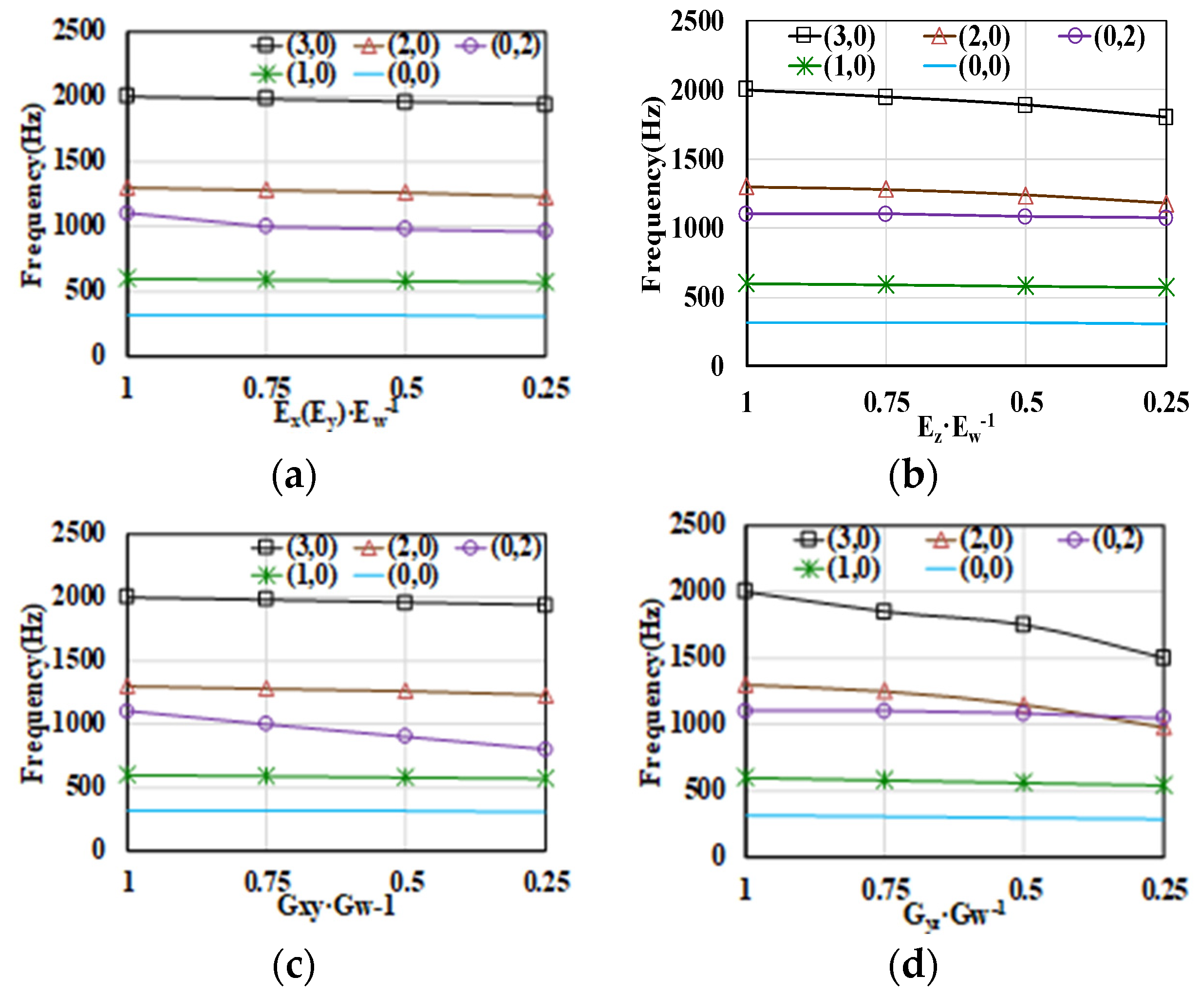
Modal and harmonic analyses were conducted by ANSYS, a structural analysis solver. As can be seen from Figure 2, radial mode (m = 0) is mainly affected by G x y and E x ( E y ), while axial mode is greatly affected by G y z ( G x z ) and G z . The higher the order of the mode, the more affected by these parameters it becomes. (m,n) represents the combination of axial and radial modes. The m represents the order of the axial modes and the n represents the order of radial modes.
The structural component design is used to ensure the acceptable deformation of the stator, including the pin and sleeve. These structural parts and equivalent winding will affect the stator mode. As can be seen in Figure 3, the mode of stator with equivalent winding will decline because of the stiffness reduction caused by equivalent winding. Nevertheless, the mode of overall stator assembly with equivalent winding and structural components will increase due to the structural support for the stator. This proves that the existence of stator support is very important for the yokeless stator. Therefore, it also provides an approach to changing the stator mode. In Figure 3, the redder the color on the chromatic scale, the greater the degree of the model deformation.
The influence of other parameters of the stator is also studied. In this article, the winding is equivalent. Winding equivalence refers to the simplification of complex winding structures during motor modal simulation. The end winding on the inner and outer circle is equivalent to the ring, and the winding in the slot is equivalent to the cuboid. The equivalent winding model structure is shown in Figure 4. The purpose of equivalent winding is to simplify the calculation process.
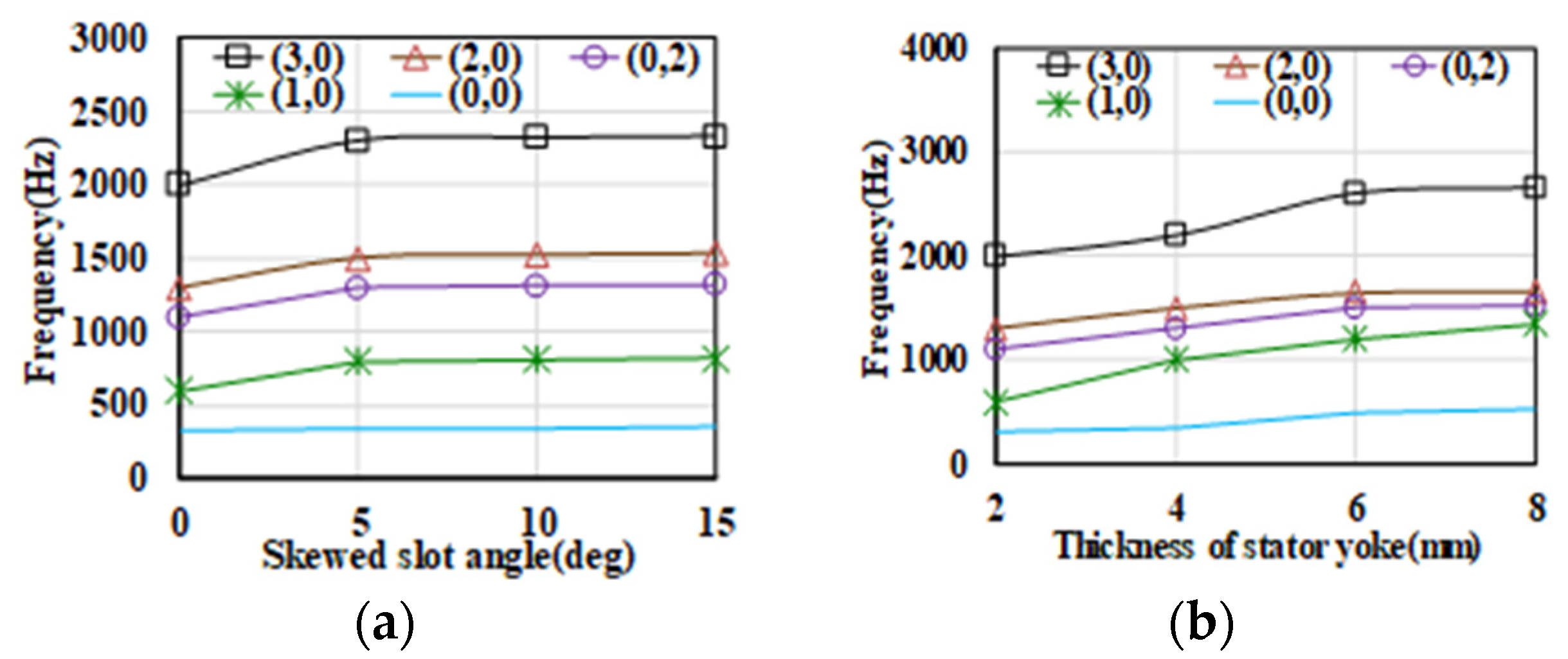
This article ensures that the effect of equivalent winding is the same as before. In Figure 5, we can see that the mode of the stator will increase with the increase in the slot skew angle and yoke thickness. When the slot skew angle and yoke thickness increase to a certain value, the mode of the stator will be almost unchanged.

3. Axial Electromagnetic Force Analysis

According to [11], the axial force under no load and load can be expressed as:
f z B z 2 2 μ 0 = B z _ m a g . λ z 2 2 μ 0 ,   u n d e r   n o   l o a d B z 2 2 μ 0 = B z _ m a g + B z _ a r m λ z 2 2 μ 0 , u n d e r l o a d
Here, f z represents the axial electromagnetic force density.
B z represents the axial air gap flux density. λ z represents the relative permeance function. B z _ m a g represents the harmonics of magnetic flux density produced by permanent magnets. B z _ a r m represents the harmonics of magnetic flux density generated by the stator currents. Equation (2) explains that the axial force is different when under no load and load. Considering the source of axial force, the f z can be classified into six categories, which are shown in Table 2.
According to Equation (2) and Table 2, the axial force of the AFPM motor with 48 slots and eight poles can be calculated. The frequency of axial force with zeroth spatial order under no load and load are listed in Table 3. The axial electromagnetic force wave is divided into three components.
  • The amplitude of axial electromagnetic force remains unchanged. This axial electromagnetic force only causes static deformation for the stator but will not cause periodic vibration on the stator surface;
  • The axial electromagnetic force is generated by harmonic interaction between the magnetic fields from stator and rotor. The electromagnetic force generated by the interaction of different order harmonics from stator or rotor itself;
  • The electromagnetic force is generated by the interaction between harmonics from stator and rotor.
Table 3. Frequency of zeroth spatial order axial force density under no load and load.
Spatial OrderConditionFrequency (A Multiple of the Mechanical Frequency)
ZerothNo load12 k
Load6 k
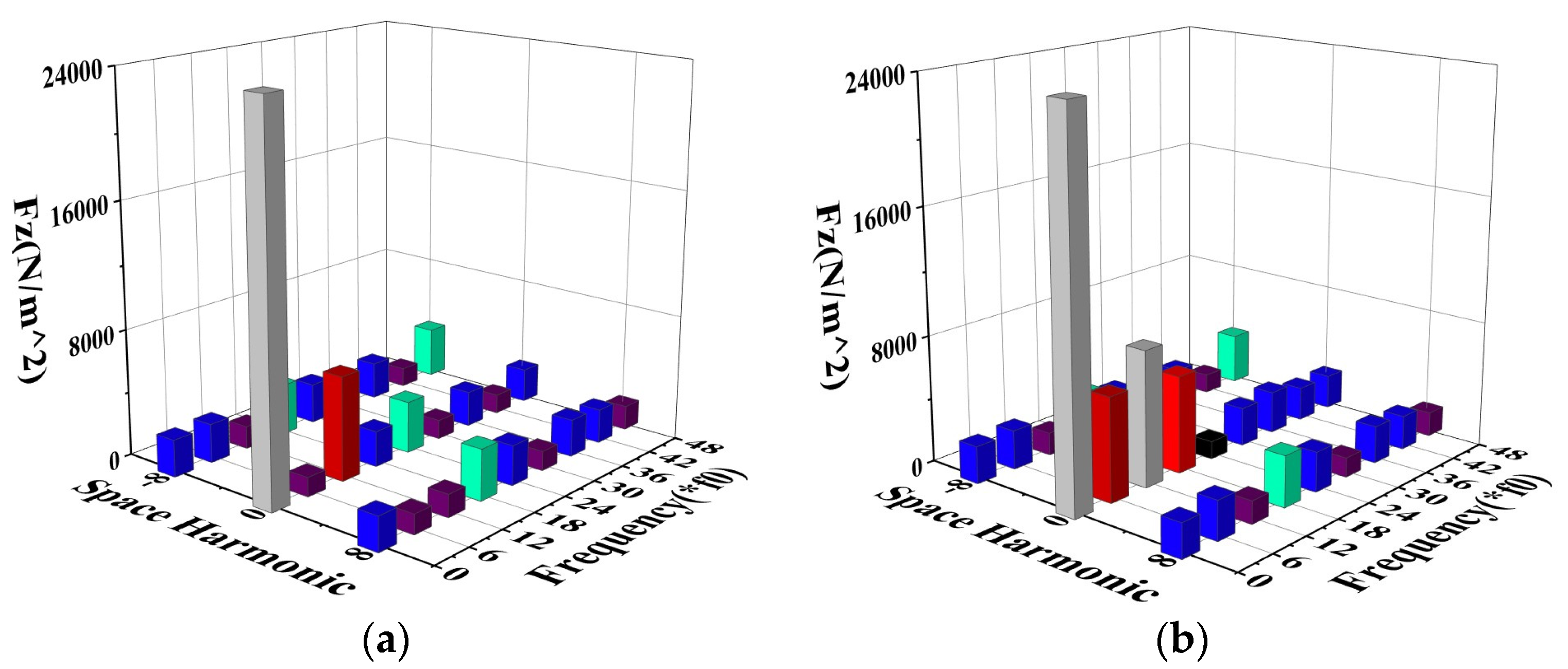
Figure 6 shows the axial force spatial order and frequency of the proposed AFPM motor under no load and load conditions. The colored columns in the picture have no practical significance, they are only for the sake of graphic aesthetics. It can be seen that the simulated spatial order and frequency of the axial force are coinciding with the theoretical analysis results in Table 3. For the 48-slot 8-pole AFPM motor, the axial force spatial order has an even relation to the number of pole pairs both under no-load and load operating conditions. It can be seen that the axial force with zeroth spatial order is playing a leading role at different frequencies. Different from the electromagnetic axial force under no load, the zeroth spatial order axial force increases significantly at 6 kf1 frequencies under load. The variation in these axial forces is the main cause of vibration and noise in the AFPM motor.

4. Vibration and Noise Analysis

The generation of vibrations and noise in motors is basically determined by the electromagnetic force and the motor modes. Therefore, research on the influence of rotor topologies on axial electromagnetic forces providing an approach for reducing vibration and noise is implemented in this article. In this section, continuous skew pole, non-equally segmented skew pole and equally segmented skew pole are processed, the diminution effect of different rotor structures on air gap magnetic field harmonics is analyzed and the influence of rotor structure on vibration and noise is then analyzed.

4.1. Continuous Skew Pole

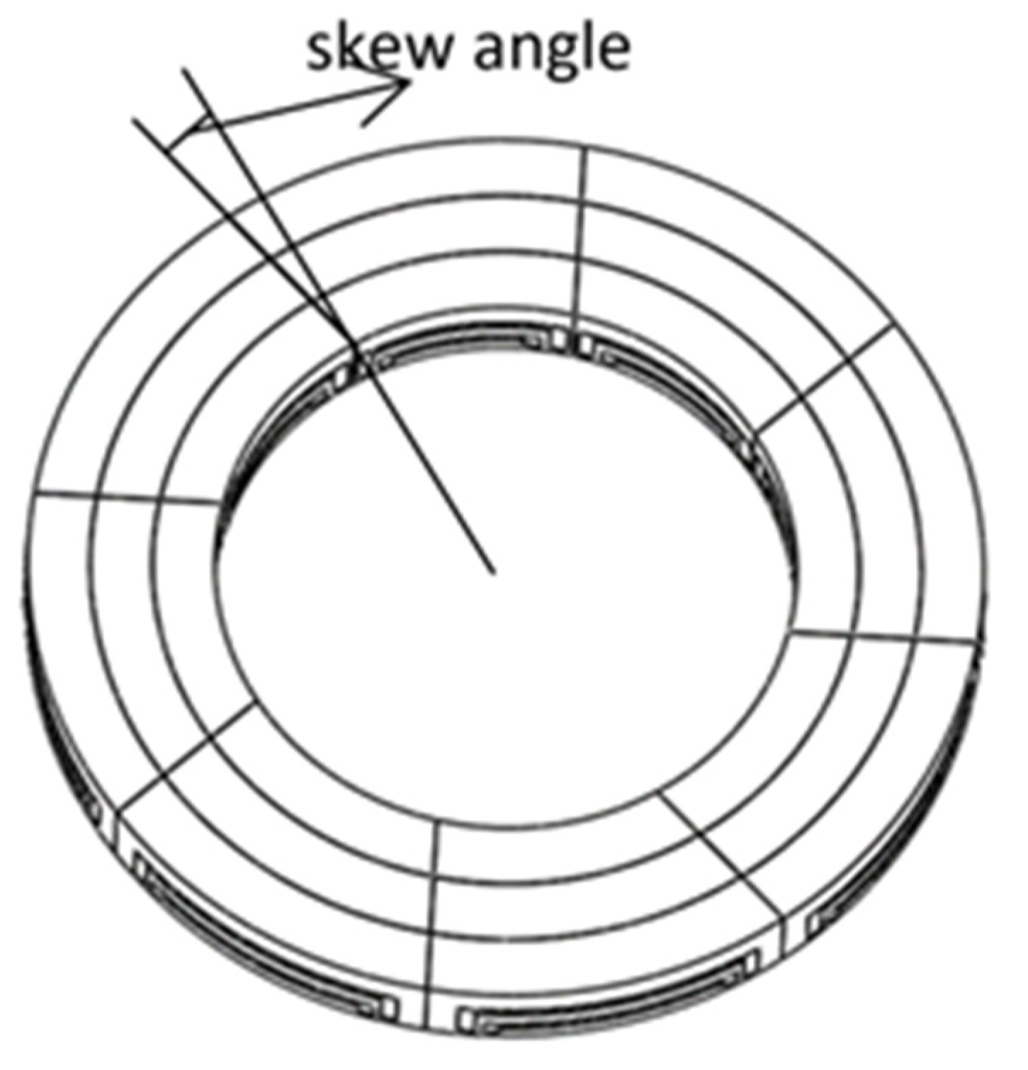
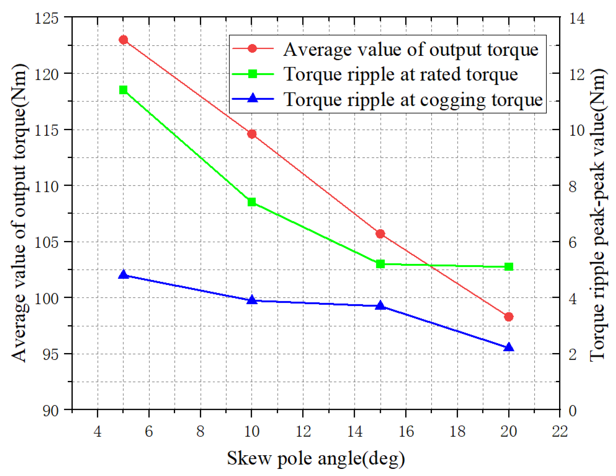
Continuous skewed rotor refers to a rotor core with an interior permanent magnet. The distribution of the inner and outer circles of the rotor core is not on the same concentric angle, but the distribution of the outer and inner circles differs by an angle, which is the angle of the skewed rotor, as shown in Figure 7. The structure of the rotor of the interior permanent magnet is shown in Figure 8. Through parametric modeling of the skew pole angles, the torque ripple and cogging torque of AFPM motors under different skew pole angles are analyzed. When the rotor had a continuous skew pole, the rotor was divided into three sections from the inside to the outside for analysis in the FEA simulation. In order to ensure the accuracy of the simulation results, different encryption methods were applied to each part of the rotor, resulting in a total mesh mass of 0.75; the number of mesh divisions is 1,125,444, and the number of mesh units is 481,224. Figure 9 shows the torque ripple result of different continuous skew angle rotors. It can be clearly seen that a continuous skew pole can reduce the ripple of cogging torque and torque ripple. This is very effective in terms of reducing vibration noise.
According to the analysis of the axial electromagnetic force of the 48-slot 8-pole motor proposed in this article in Section 3, the influence of mechanical frequency electromagnetic force under order 12 k and 6 k should be given attention. The corresponding frequencies are 600 Hz and 300 Hz. As shown in Figure 6, the electromagnetic force density under no-load and load has been displayed to prove the correctness of formula calculation.

4.2. Segmented Skew Pole

Since the rotor core is made of silicon steel sheet to be wound with the help of a mold and tooling, the continuous skew pole is not easy to realize in actual manufacturing. In practice, manufacturability needs to be considered from the perspective of engineering applications. This section carries out the non-equally segmented skew pole scheme.
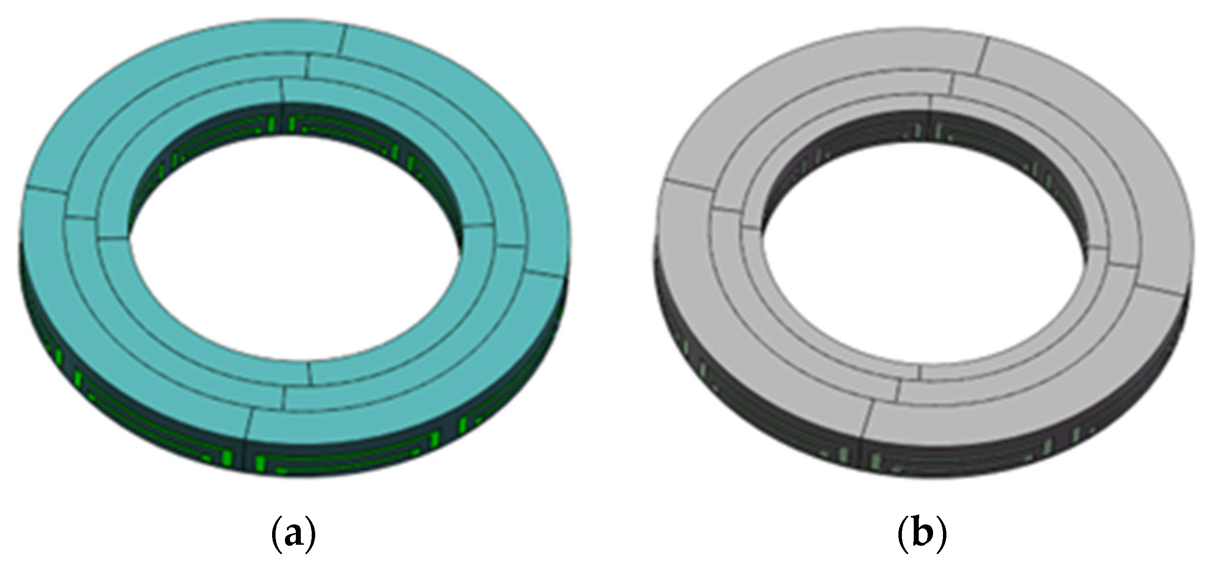
As shown in Figure 10, the segmented skew rotor adopts two different methods. One is to divide the rotor into three sections equally from the inside to outside. The length of the three sections is kept the same in the radial direction, and the mechanical angle difference of the three sections is the same. The other one is to divide the rotor into three unequal sections from the inside to outside. The length of the three sections of the rotor in the radial direction is different but the mechanical angle difference of the three sections of the rotor is the same. The proportion of the three sections and the skew angle are modeled parametrically.
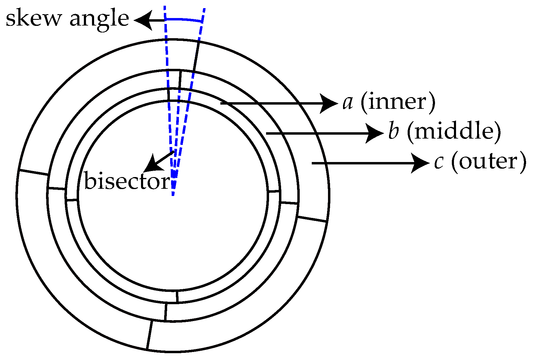
In order to investigate thoroughly the relationship between the proportion of three-segment rotors and motor performance, as well as vibration and noise, parametric modeling of the rotors is carried out as follows. The inner and outer diameters of the rotors remain unchanged. The proportions of the radius of the inner, middle and outer rotor segments are represented with a, b and c, respectively. The diagram of parametric modeling of the segmented skew pole is presented in Figure 11. As a result, different combinations of a–b–c are used to represent the combination of the proportion of three rotor segments. The purpose of this program is to prove that the effect of a non-equally segmented skew rotor in terms of reducing vibration and noise will be better than that of an equally segmented skew rotor.
As can be seen from Table 4:
  • When the angle of the non-equally segmented skew pole is 5 deg, the best segmented ratio is 2:1:2. Compared with the segmented skew pole, the torque output changes from 111.5 Nm to 118 Nm and the ratio of output torque fluctuation decreases from 8.05% to 7.54%.
  • When the angle of the non-equally segmented skew pole is 10 deg, the best segmented ratio is 1:1:2. Compared with the segmented skew pole, the torque output changes from 102.6 Nm to 114.6 Nm, while the proportion of output torque fluctuation decreases from 6.7% to 6.45%.
  • When the angle of the non-equally segmented skew pole is 15 deg, the best segmented ratio is 1:1:2. Compared with the segmented skew pole, the torque output changes from 93.4 Nm to 105.7 Nm and the ratio of output torque fluctuation decreases from 6.2% to 4.92%.
  • When the angle of the non-equally segmented skew pole is 20 deg, the best segmented ratio is 1:1:2. Compared with the segmented skew pole, the torque output changes from 83.15 Nm to 98.3 Nm and the proportion of output torque fluctuation decreases from 5.3% to 5.2%.
Table 4. Influence of unequal segmental skew pole on motor performance.
Skew Pole Angle
(deg)
Section Ratio (a–b–c)Peak-Peak Value of Cogging Torque (Nm)Average Value of Output Torque (Nm)Rated Torque Peak-Peak Torque Ripple (Nm)Torque Peak-Peak Percent Fluctuation, Referred to Average Torque (%)
5 deg1:1:24.812311.49.26
2:1:23.71188.97.54
1:2:24.312310.378.43
2:2:14.01117.810.68.99
10 deg1:1:23.9114.67.46.45
2:1:23.6107.998.34
1:2:22.41137.486.62
2:2:15.31079.628.99
15 deg1:1:23.7105.75.24.92
2:1:23.895.857.98.24
1:2:23.6104.27.317.02
2:2:13.891.67.27.86
20 deg1:1:22.2198.35.15.2
2:1:22.6179.945.036.29
1:2:22.7192.16.316.85
2:2:13.473.656.258.48
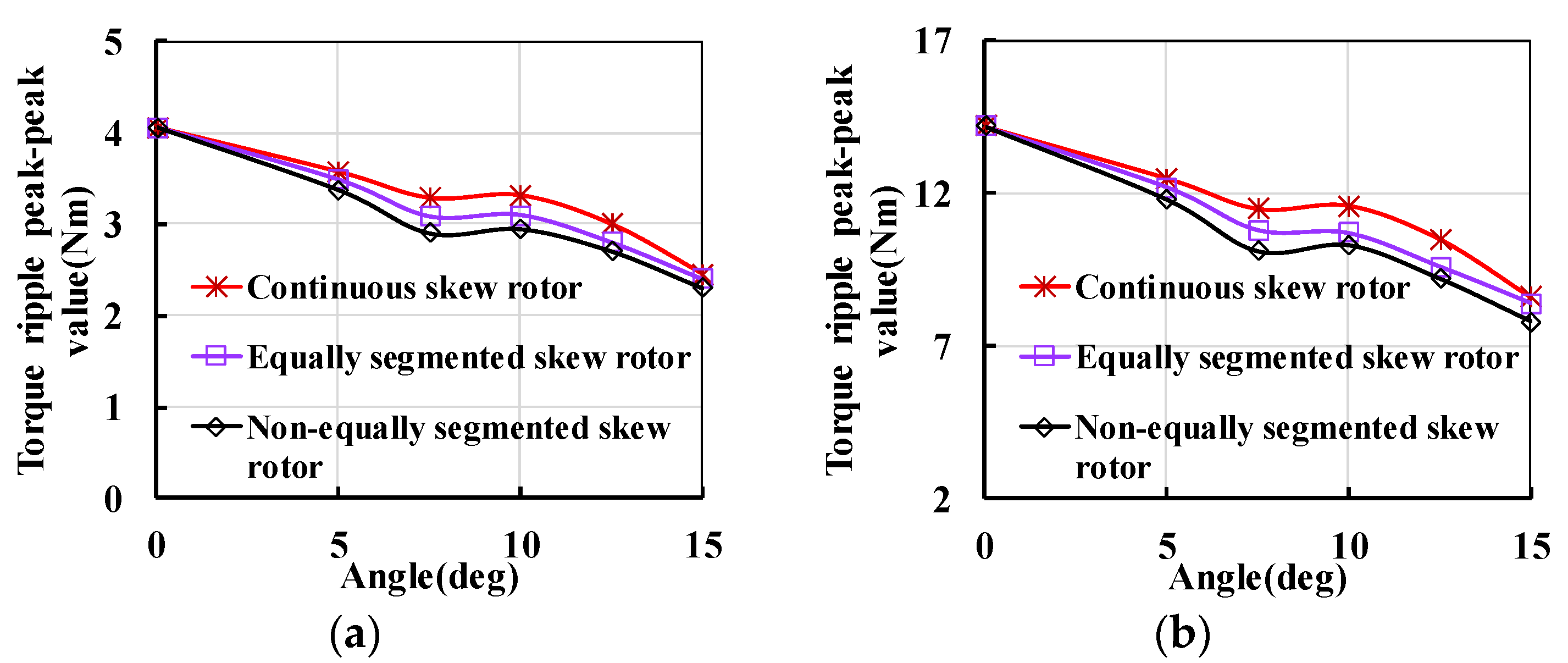
The above results indicate that, compared with the equally segmented skew pole, the non-equally segmented skew rotor has a better effect on reducing the torque ripple of the motor. As shown in Figure 12, the most effective effect on reducing torque ripple is adopting a non-equally segmented skew rotor. The effect of reducing the output torque caused by the skew pole is weakened and the reducing value of output torque is smaller. This indicates that the non-equally segmented skew rotor can better reduce the vibration and noise of the motor while maintaining the motor output performance.
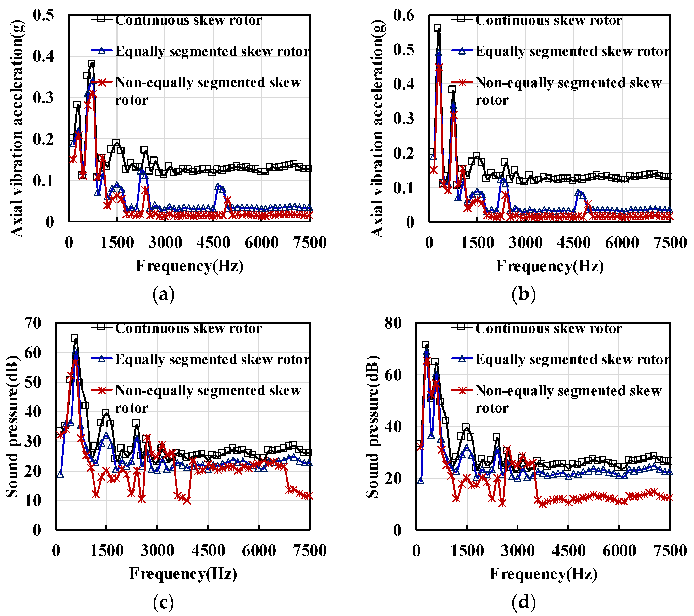
Using the Maxwell Workbench multiphysic coupling model calculation, the vibration performance of a normal rotor, an equally segmented skew pole and non-equally segmented skew pole motors at different skew pole angles under optimal proportions of a–b−c are compared. It can be seen from Figure 13 that the motor adopting a non-equally segmented skew rotor has the lowest vibration and noise performance. The result is displayed when the AFPM motor works at 3000 r/min. According to Section 3, the frequency of electromagnetic force under no-load and load are 600 kHz and 300 kHz. As shown in Figure 13, it is noted that the frequency of maximum vibration amplitude under no-load and load is 600 Hz and 300 Hz, which confirms the analysis correctness of the analysis in Section 3. More importantly, the result in Figure 13 also illustrates that the vibration and noise are reduced at almost all the range of frequency when adopting a non-equally segmented skew rotor. It can be concluded from Table 4 that, when each segmented ratio is suitable, the non-equally segmented skew rotor can better reduce the vibration and noise. Meanwhile, the non-equally segmented skew rotor results in less loss of output torque compared to the equally segmented skew rotor and continuous skew rotor.

5. Prototype and Experiment

This section introduces motor performance and vibration tests. The vibration acceleration sensor is installed on the surface of the rear end cover and housing of the AFPM motor to measure the vibration acceleration in the radial and axial directions. The parameters of the vibration acceleration sensor are listed in Table 5. The measured data are processed by the data collector and uploaded to the computer software for analysis. The experimental curves of the vibration acceleration in the time domain and the frequency domain are obtained.
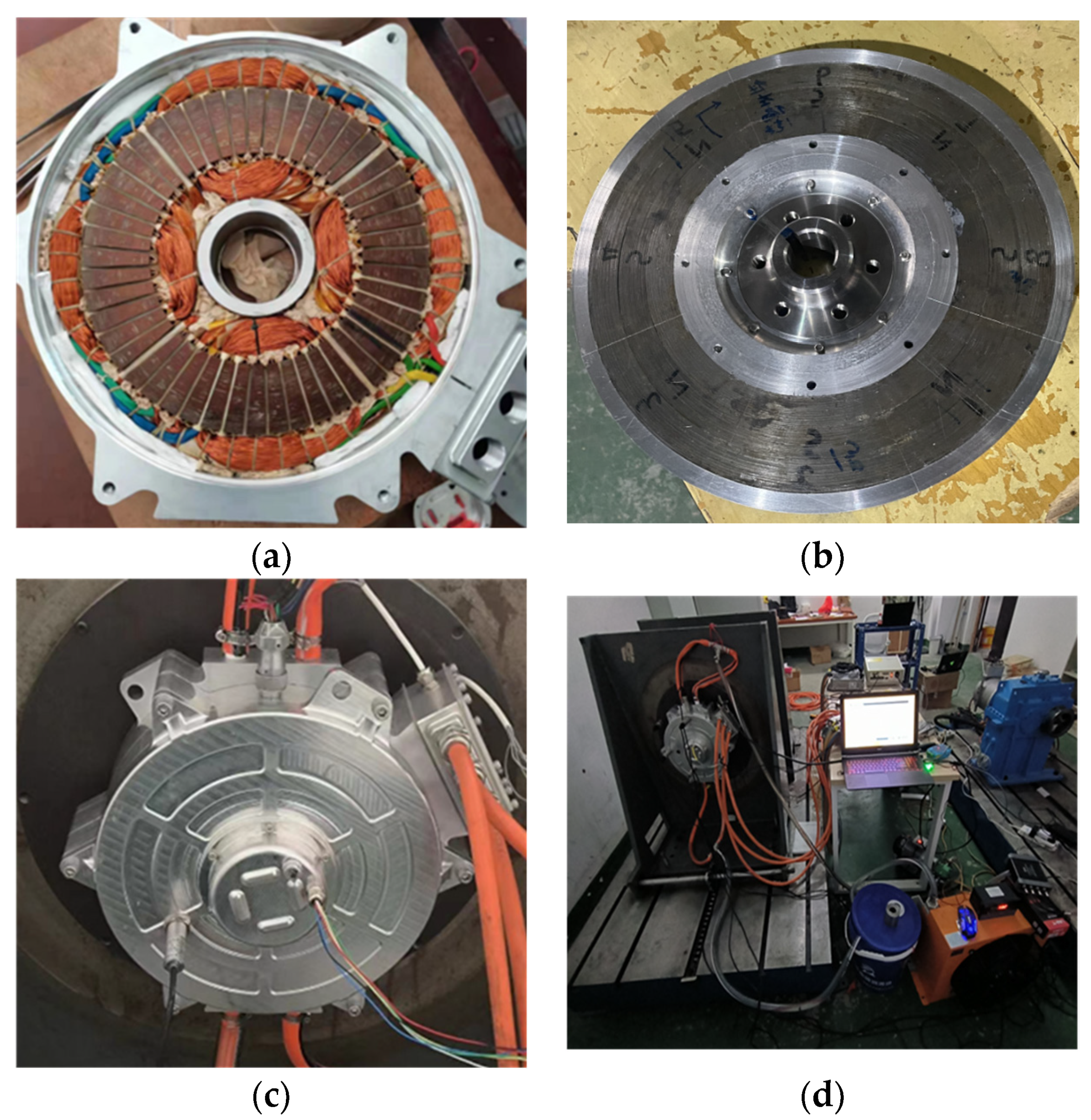
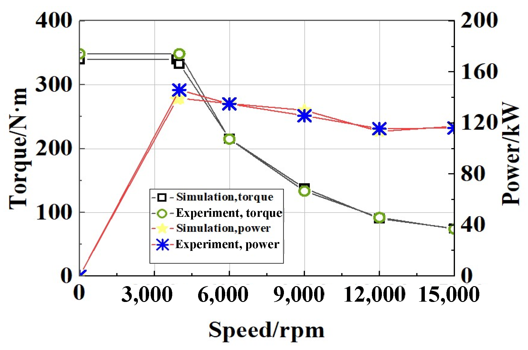
The prototype has been manufactured and tested to verify the correctness of the FEA method employed in this paper. Figure 14 shows the AFPM motor and bench in the experiment. The developed AFPM motor adopts an equally segmented skew pole for manufacturability. The measured and 3-D FEA predicted line-to-line back-EMF waveforms at 3600 r/min are shown in Figure 15. The FEA value of back-EMF agrees well with the measured data. The measured torque/power–speed curves are shown in Figure 15, respectively. The predicted values in Figure 16 agree well with the measured data. The consistency of the results proves that the manufacturing of the prototype AFPM motor follows the setting of the simulation well.
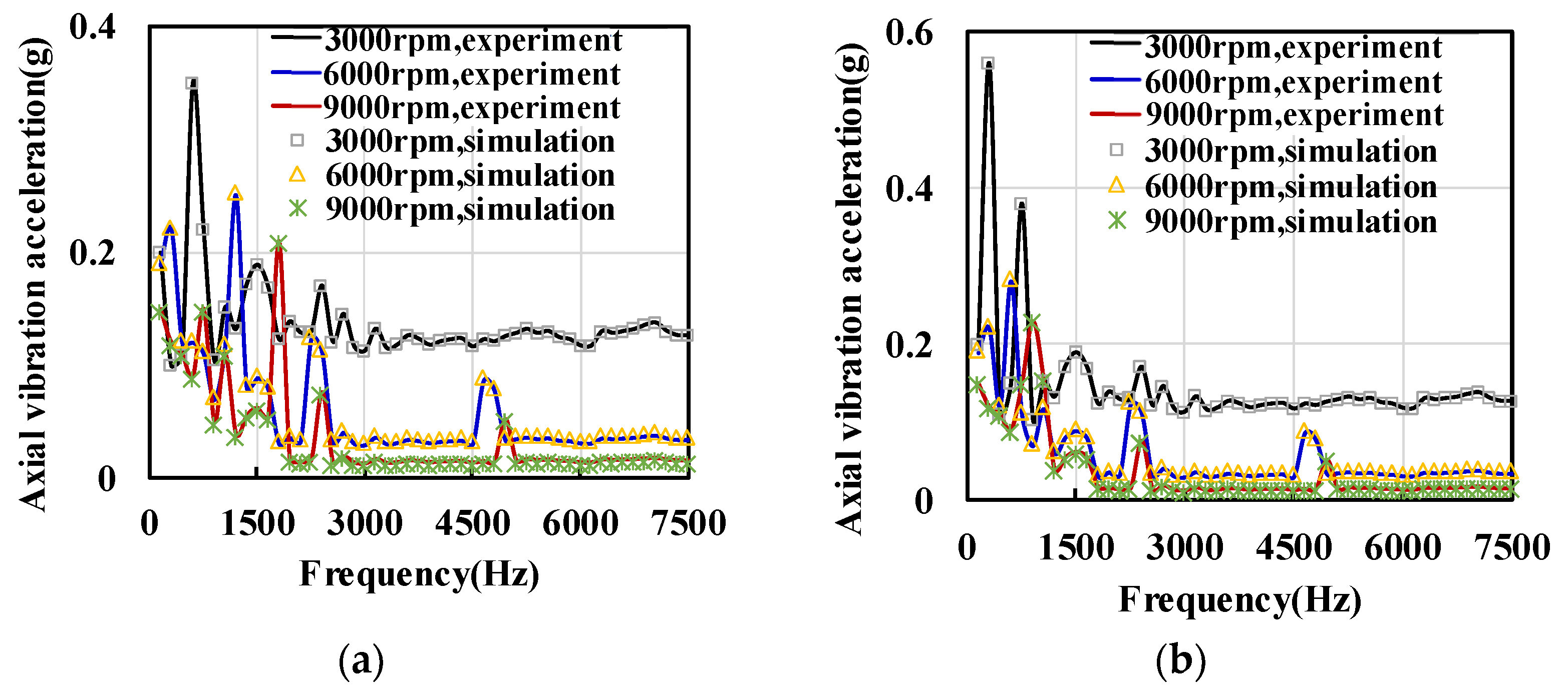
The vibration displacement in the rotor outer surface is tested on the surface of the rear end cover at different speeds under no load and load, which is detailed in Table 6. The result in Figure 14a,b shows that the 12 k frequency of the electromagnetic force plays a leading role under no load and that the 6 k frequency of electromagnetic force is associated with the vibration under load. It can be seen that the calculated vibration can match the tested results at the resonance frequencies. Meanwhile, in Figure 17, when the frequency of the electromagnetic force is closer to the frequency of the zero-mode of the stator, the amplitude of vibration caused by electromagnetic force is much more serious. More interestingly, the amplitude of axial vibration acceleration reduces gradually with the increase in speed. A reasonable explanation for this is that the frequency of the electromagnetic force will increase with the increase in speed while the difference with the zero-mode frequency of stator increases. Although the amplitude of the electromagnetic force increases, the vibration will decrease.
Figure 18 shows the data of radial vibration acceleration. It can be seen that the amplitude of radial vibration acceleration is far less than axial vibration acceleration. This indicates that axial vibration is the main element causing noise in the AFPM motor. Compared to radial flux motors, an axial flux motor should pay attention to axial vibration and zero-order mode. The zero-order mode in the AFPM motor is much lower compared to the radial flux motor. Therefore, the axial electromagnetic force can lead to large vibrations when its frequency is close to zero-order mode in the axial direction.
The experiment compared the simulation and experimental data under no-load and load. The result verified the correctness of the finite element simulation and the theory studied in this article. Although the final prototype did not adopt the scheme of unequal skew poles, the approximation of the results can also prove the credibility of the finite element results of unequal skew poles.

6. Conclusions

In this article, a new single stator double rotor AFPM motor with a yokeless stator and interior PM rotor is presented and designed for EV traction application. The axial electromagnetic force and vibroacoustic characteristics of the AFPM motors are investigated in this study. A non-equally segmented skew rotor structure is proposed. The axial electromagnetic force and vibrations are investigated and compared among the three different types of rotor skew poles. The main conclusions are as follows.
  • The theoretical calculation of axial electromagnetic force generated by the air-gap magnetic field of an AFPM motor is derived for a single stator double rotor AFPM motor, and the zero-mode frequencies of the axial electromagnetic force of 48-slot-8pole AFPM topology under no-load and load are 12 k and 6 k, respectively.
  • The anisotropic material has an important impact on the stator mode due to the wounded silicon steel sheet. It provides an approach to the change stator mode frequency. Moreover, the structural support for the yokeless stator can improve stator stiffness and increase the stator mode frequency.
  • The decrease in motor performance caused by the non-equally segmented skew pole is weaker than that caused by the equal segment skew pole, which indicates that the unequally segmented skew pole is an effective way to reduce the vibration and noise of the AFPM motor.
  • Due to poor manufacturability, it is difficult to implement continuously segmented skew pole rotors for AFPM motors in the mass production process. Therefore, the non-equally segmented skew pole rotor will be an effective method for reducing vibration and noise while ensuring motor performance.

Author Contributions

Conceptualization, X.Y., Q.W. and Y.F.; methodology, Q.W.; software, X.Y., H.C. and J.Z.; validation, X.Y. and W.G.; formal analysis, X.Y.; investigation, X.Y.; resources, X.Y. and Y.F.; data curation, X.Y. and Q.W.; writing—original draft preparation, X.Y.; writing—review and editing, X.Y., Q.W. and J.Z.; visualization, X.Y.; supervision, X.Y. and H.C.; project administration, X.Y. and Y.F.; funding acquisition, X.Y. All authors have read and agreed to the published version of the manuscript.

Funding

This work was supported by the Jiangsu Provincial Key Research And Development Project (BE2021016-1), the Natural Science Foundation of the Jiangsu Province under Grant (BK20220957) and Aeronautical Science Foundation of China (ASFC-20230007059001).

Data Availability Statement

The original contributions presented in the study are included in the article; further inquiries can be directed to the corresponding author.

Conflicts of Interest

The authors declare no conflicts of interest.

References

  1. Kahourzade, S.; Mahmoudi, A.; Ping, H.W.; Uddin, M.N. A comprehensive review of axial-flux permanent-magnet machines. Can. J. Electr. Comput. Eng. 2014, 37, 19–33. [Google Scholar] [CrossRef]
  2. Wu, S.; Zuo, S.; Wu, X.; Lin, F.; Zhong, H.; Zhang, Y. Vibroacoustic prediction and mechanism analysis of claw pole alternators. IEEE Trans. Ind. Electron. 2017, 64, 4463–4473. [Google Scholar] [CrossRef]
  3. Zhu, Z.Q.; Howe, D. Instantaneous magnetic field distribution in brushless permanent magnet DC motors. III. Effect of stator slotting. IEEE Trans. Magn. 1993, 29, 143–151. [Google Scholar] [CrossRef]
  4. Zhu, Z.Q.; Howe, D. Instantaneous magnetic field distribution in permanent magnet brushless DC motors. IV. Magnetic field on load. IEEE Trans. Magn. 1993, 29, 152–158. [Google Scholar] [CrossRef]
  5. Zhu, Z.Q.; Xia, Z.P.; Wu, L.J.; Jewell, G.W. Analytical modeling and finite-element computation of radial vibration force in fractional-slot permanent-magnet brushless machines. IEEE Trans. Ind. Appl. 2010, 46, 1908–1918. [Google Scholar] [CrossRef]
  6. Lin, C.; Fahimi, B. Prediction of acoustic noise in switched reluctance motor drives. IEEE Trans. Energy Convers. 2014, 29, 250–258. [Google Scholar] [CrossRef]
  7. Fakam, M.; Hecquet, M.; Lanfranchi, V.; Randria, A. Design and magnetic noise reduction of the surface permanent magnet synchronous machine using complex air-gap permeance. IEEE Trans. Magn. 2015, 51, 1–9. [Google Scholar] [CrossRef]
  8. Yang, H.; Chen, Y. Influence of radial force harmonics with low mode number on electromagnetic vibration of PMSM. IEEE Trans. Energy Convers. 2014, 29, 38–45. [Google Scholar] [CrossRef]
  9. Jung, J.-W.; Lee, S.-H.; Lee, G.-H.; Hong, J.-P.; Lee, D.-H.; Kim, K.-N. Reduction design of vibration and noise in IPMSM type integrated starter and generator for HEV. IEEE Trans. Magn. 2010, 46, 2454–2457. [Google Scholar] [CrossRef]
  10. Torregrossa, D.; Fahimi, B.; Peyraut, F.; Miraoui, A. Fast computation of electromagnetic vibrations in electrical machines via field reconstruction method and knowledge of mechanical impulse response. IEEE Trans. Ind. Electron. 2012, 59, 839–847. [Google Scholar] [CrossRef]
  11. Park, S.; Kim, W.; Kim, S.-I. A numerical prediction model for vibration and noise of axial flux motors. IEEE Trans. Ind. Electron. 2014, 61, 5757–5762. [Google Scholar] [CrossRef]
  12. Cao, G.-Z.; Li, L.-L.; Huang, S.-D.; Li, L.-M.; Qian, Q.-Q.; Duan, J.-A. Nonlinear modeling of electromagnetic forces for the planar-switched reluctance motor. IEEE Trans. Magn. 2015, 51, 1–5. [Google Scholar] [CrossRef]
  13. Deng, W.; Zuo, S. Axial force and vibroacoustic analysis of external-rotor axial-flux motors. IEEE Trans. Ind. Electron. 2018, 65, 2018–2030. [Google Scholar] [CrossRef]
  14. Zuo, S.; Lin, F.; Wu, X. Noise analysis, calculation, and reduction of external rotor permanent-magnet synchronous motor. IEEE Trans. Ind. Electron. 2015, 62, 6204–6212. [Google Scholar] [CrossRef]
  15. Lu, Y.; Li, J.; Qu, R.; Ye, D.; Lu, H. Electromagnetic force and vibration study on axial flux permanent magnet synchronous machines with dual three-phase windings. IEEE Trans. Ind. Electron. 2020, 67, 115–125. [Google Scholar] [CrossRef]
  16. Shin, H.-J.; Choi, J.-Y.; Park, Y.-S.; Koo, M.-N.; Jang, S.-M.; Han, H. Electromagnetic vibration analysis and measurements of double-sided axial-flux permanent magnet generator with slotless stator. IEEE Trans. Magn. 2014, 50, 1–4. [Google Scholar] [CrossRef]
  17. Wu, S.; Tong, W.; Sun, R.; Tang, R. A generalized method of electromagnetic vibration analysis of amorphous alloy permanent magnet synchronous machines. IEEE Trans. Magn. 2018, 54, 1–5. [Google Scholar] [CrossRef]
  18. Wei, M.; Zhang, C.; Gao, Y.; Qing, Y. Comparison of vibration and noise characteristics between radial flux PMSMs and axial flux PMSMs. In Proceedings of the 2022 25th International Conference on Electrical Machines and Systems (ICEMS), Chiang Mai, Thailand, 29 November–2 December 2022. [Google Scholar] [CrossRef]
  19. Wang, X.; Zhang, Y.; Li, N. Analysis and reduction of electromagnetic noise of yokeless and segmented armature axial flux motor. In Proceedings of the 2022 25th International Conference on Electrical Machines and Systems (ICEMS), Chiang Mai, Thailand, 29 November–2 December 2022. [Google Scholar] [CrossRef]
  20. Wang, K.; Zhu, Z.Q.; Ren, Y.; Ombach, G. Torque improvement of dual three-phase permanent-magnet machine with third-harmonic current injection. IEEE Trans. Ind. Electron. 2015, 62, 6833–6844. [Google Scholar] [CrossRef]
  21. Polat, M.; Yildiz, A.; Akinci, R. Performance analysis and reduction of torque ripple of axial flux permanent magnet synchronous motor manufactured for electric vehicles. IEEE Trans. Magn. 2021, 57, 1–9. [Google Scholar] [CrossRef]
  22. Aydin, M.; Huang, S.; Lipo, T.A. Design and 3D electromagnetic field analysis of non-slotted and slotted TORUS type axial flux surface mounted permanent magnet disc machines. In Proceedings of the IEEE Int. Electric Mach. Drives Conf. (IEMDC), Cambridge, MA, USA, 17–20 June 2001. [Google Scholar] [CrossRef]
  23. Pellegrino, G.; Vagati, A.; Guglielmi, P.; Boazzo, B. Performance comparison between surface-mounted and interior PM motor drives for electric vehicle application. IEEE Trans. Ind. Electron. 2012, 59, 803–811. [Google Scholar] [CrossRef]
  24. Sun, S.; Jiang, F.; Li, T.; Xu, B.; Yang, K. Comparison of a multi-stage axial flux permanent magnet machine with different stator core materials. IEEE Trans. Appl. Supercond. 2020, 30, 1–6. [Google Scholar] [CrossRef]
  25. Geng, W.; Zhang, Z. Investigation of a new ironless-stator self-bearing axial flux permanent magnet motor. IEEE Trans. Magn. 2016, 52, 1–4. [Google Scholar] [CrossRef]
  26. Geng, W.; Zhang, Z.; Li, Q. High torque density fractional-slot concentrated-winding axial-flux permanent-magnet machine with modular SMC stator. IEEE Trans. Ind. Appl. 2020, 56, 3691–3699. [Google Scholar] [CrossRef]
  27. Geng, W.; Wang, Y.; Wang, J.; Hou, J.; Guo, J.; Zhang, Z. Comparative study of yokeless stator axial-flux PM machines having fractional slot concentrated and integral slot distributed windings for electric vehicle traction applications. IEEE Trans. Ind. Electron. 2023, 70, 155–166. [Google Scholar] [CrossRef]
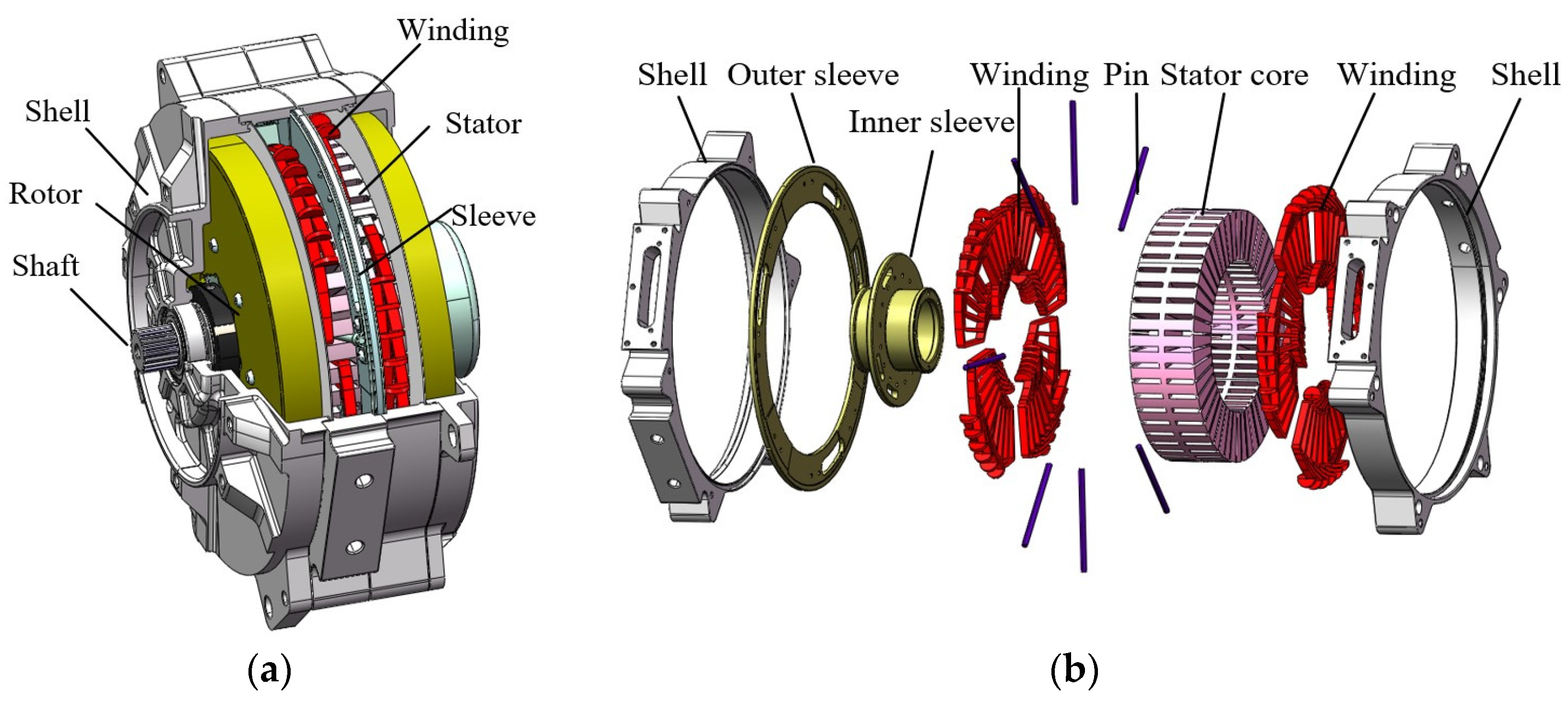
Figure 1. Configuration of the proposed AFPM motor. (a) Overall structure. (b) Yokeless stator assembly.
Wevj 15 00335 g001
Figure 2. Influence of material-defined parameters on modes. (a) The impact of E x ( E y ). (b) The impact of E z . (c) The impact of G x y . (d) The impact of G x z .
Wevj 15 00335 g002
Figure 3. The structure and mode of yokeless stator. (a) Yokeless stator core. (b) Zeroth order mode of stator core (298.2 Hz). (c) Yokeless stator with equivalent winding. (d) Zeroth order mode of stator with equivalent winding (287.6 Hz). (e) Yokeless stator with equivalent winding and structural part. (f) Zeroth order mode of stator with equivalent winding and structural part (346 Hz).
Wevj 15 00335 g003
Figure 4. The equivalent winding model structure.
Wevj 15 00335 g004
Figure 5. Influence of stator structure on mode. (a) The influence of skewed slot angle on the mode. (b) Influence of stator yoke thickness on the mode.
Wevj 15 00335 g005
Figure 6. Spatial orders and frequency of axial force. (a) Under no-load. (b) Under load.
Wevj 15 00335 g006
Figure 7. The diagram of continuous skew pole.
Wevj 15 00335 g007
Figure 8. The structure of the rotor of the built-in permanent.
Wevj 15 00335 g008
Figure 9. Influence of skew pole on the electromagnetic torque ripple, cogging torque and output torque.
Wevj 15 00335 g009
Figure 10. Rotor segmented skew pole methods. (a) The rotor is equally divided into segmented skew poles. (b) The rotor is not equally divided into segmented skew poles.
Wevj 15 00335 g010
Figure 11. The diagram of parametric modeling of segmented skew pole.
Wevj 15 00335 g011
Figure 12. Influence of skew pole methods with different angles on torque. (a) Influence on cogging torque. (b) Influence on rated torque.
Wevj 15 00335 g012
Figure 13. Comparison of three kinds of skew rotor. (a) Comparison of acceleration under no load. (b) Comparison of acceleration under load. (c) Comparison of noise under no load. (d) Comparison of noise under load.
Wevj 15 00335 g013
Figure 14. Comparison of experimental components. (a) Stator. (b) Rotor. (c) Complete machine. (d) Experimental bench.
Wevj 15 00335 g014
Figure 15. Measured and simulated line-to-line back-EMF waveforms @3600 r/min.
Wevj 15 00335 g015
Figure 16. Torque/power–speed curves of simulation and experiment.
Wevj 15 00335 g016
Figure 17. Comparison of different speed data. (a) No load. (b) Load.
Wevj 15 00335 g017
Figure 18. Radial vibration acceleration data.
Wevj 15 00335 g018
Table 1. Motor parameters.
ParametersValue
Outer diameter of stator and rotor220 mm
Inner diameter of stator and rotor130 mm
Air-gap length1.5 mm
Number of slots48
Number of poles8
Number of phases3
Rated power70 kW
Peak power120 kW
Rated speed (frequency)6000 r/min (100 Hz)
Peak speed (frequency)15,000 r/min (250 Hz)
Table 2. Source, spatial order, and frequency of axial force density.
ItemSourceSpatial OrderFrequency
1PM field 2 μ 2 μ f 1 / p
2Interaction of PM field and stator slotting 2 [ 2 μ ± k Q 1 ] 2 μ f 1 / p
3Interaction of PM field and armature reaction field μ ± υ ( μ ± p ) f 1 / p
4Armature reaction field υ 1 + υ 2 2 f 1
5Interaction of PM field, armature reaction field, and stator slotting ( μ ± k Q 1 ) ± υ ( μ ± p ) f 1 / p
6Interaction of armature reaction field and stator slotting ( υ 1 ± υ 2 ) ± k Q 1 2 f 1
Table 5. Parameters of vibration acceleration sensor.
ParametersValue
Sensitivity100 mV/g
Range10 g
Frequency response0.5 kHz–6 kHz
Resolution100 μg
Operating voltage18 V–28 V DC
Output impedance<100 Ω
Table 6. Experiment conditions.
SpeedVibration Frequency under no LoadVibration Frequency under LoadDC Bus
3000 r/min600 Hz300 Hz350 V
6000 r/min1200 Hz600 Hz350 V
9000 r/min1800 Hz900 Hz350 V
Disclaimer/Publisher’s Note: The statements, opinions and data contained in all publications are solely those of the individual author(s) and contributor(s) and not of MDPI and/or the editor(s). MDPI and/or the editor(s) disclaim responsibility for any injury to people or property resulting from any ideas, methods, instructions or products referred to in the content.