Abstract
As the market for hybrid and electric vehicles expands, electric motor production and testing technology must be continuously improved to meet the cost and quality requirements of mass production. In order to detect faults in motors during the production process, a condition monitoring tool is used for the motor end line. During most condition monitoring, the motor operates in a static state where the speed of the motor remains constant and the voltage/current is recorded for a certain period. This process usually takes a long time and requires a loader to drag the motor to a standstill at a constant speed. In this paper, various transient process testing methods are introduced. For these processes, only transient operation of the motor, such as acceleration, loss, or a short circuit, is required. By analyzing the measurement results and simulation results of motor models, unhealthy motors can be detected more effectively.
1. Introduction
The installation of high-energy density batteries and the application of fast charging technology in electric vehicles meet the requirements of energy conservation and emission reduction. In addition, since the electric motor in electric vehicles is a controllable motor, control methods such as direct torque control or vector control can be used to control a single motor in order to achieve flexibility and maneuverability in controlling electric vehicles. It is precisely because of the advantages of electric vehicles mentioned above that they are becoming increasingly common in real life [1].
In recent years, electric vehicles (EVs) have become a new object of automotive development due to their enormous advantages in energy conservation, emission reduction, low-carbon utilization, and environmental protection. Firstly, EVs use electricity as a direct source of clean energy, including hydro, nuclear, wind, solar, geothermal, etc., thereby reducing the dependence of cars on traditional fossil fuels. Secondly, EVs use electric motors to convert battery energy into kinetic energy, effectively reducing noise pollution and exhaust emissions. Finally, the rapid development of battery energy storage technology, power electronics technology, and smart grid technology has provided great convenience for EV charging in the grid [2].
Electronic mobility has become an increasingly important issue for car manufacturers and auto suppliers in recent years. With the increasing number of electric/hybrid cars and the rapid growth of electric motor production, new requirements have been put forward for the assembly and testing technology of production lines. At present, induction motors and permanent magnet synchronous motors motor are the most commonly used motor types in electric and hybrid vehicles.
Induction motors can be examined through reference to Kim [3]. Specific detection methods and parameters are also specified in the technical standards, which are not mentioned here.
This paper mainly introduces a test method for permanent magnet synchronous motors for hybrid and electric vehicles. For different types of PMSM, different condition monitoring methods are applicable.
At present, most motor production enterprises of automobile branches have adopted 100% offline detection in motor production lines. The most common method is to attach the motor to the loader, which acts as a definite load and drags the motor to a certain speed level.
In this process, faults in the motor can be detected by comparing the measured voltage, current, or speed with a given limit. One drawback of this approach is the length of time it takes to test a smooth process and the large investment in loaders, including cooling systems.
Other methods used for motor fault detection, such as motor current signal analysis, noise vibration harshness (NVH) analysis, etc., also need to operate at rest. In MCSA, different characteristic frequencies can be detected by Fourier analysis or wavelet analysis, and thus the motor fault index can be obtained. NVH analysis requires the motor to maintain a constant speed for a certain period of time in order to measure the vibration and noise levels of the motor.
With the increase in the output of PMSMs, these methods are not suitable for conventional testing because of the long testing time. In order to shorten the inspection time on the production line, this paper also introduces other methods, namely, transient process inspection.
Transient processes such as switch transients [4] are used in IGBT fault detection, as well as some transient processes, to detect thermal changes in electrical components [5]. The MCSA method also has applications in transient processes, where it is known as transient motor current signal analysis (TMCSA) [6].
Transient processes in this paper refer to the process of motor operating state change; these changes may be caused by changes in electrical or mechanical environmental conditions. In the third section, we will discuss the different dynamic operation modes. By analyzing the parameters measured in the transient process, we can detect motor faults on the production line.
Using only dynamic processes, the loading machine is no longer necessary, and therefore the mechanical connection to it can be abandoned. This has greatly reduced investment costs and testing.
2. Fault Detection in Stationary Processes
Examining the practicality of identifying motor malfunctions in fleeting processes involves using steady-state behavior as a benchmark and contrasting the outcomes of these transient activities. Figure 1 displays a simulation model of a motor’s electromagnetic structure. The motor model is an 8-pole 48-slot motor, and the permanent magnet adopts a double-V structure, which can effectively concentrate the magnetic field and improve the motor efficiency.
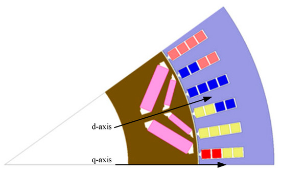
Figure 1.
Electromagnetic simulation model.
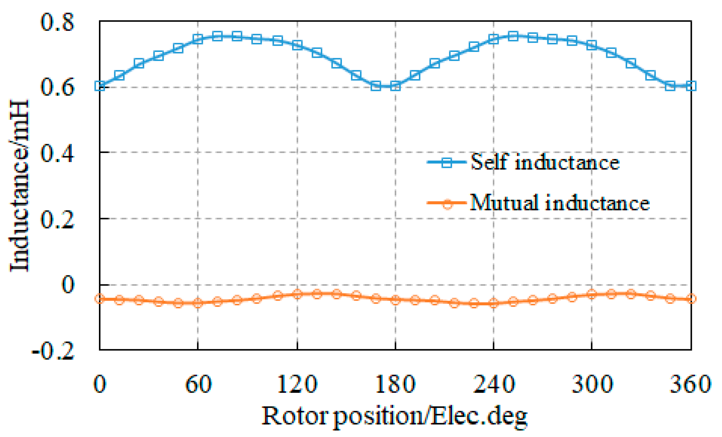
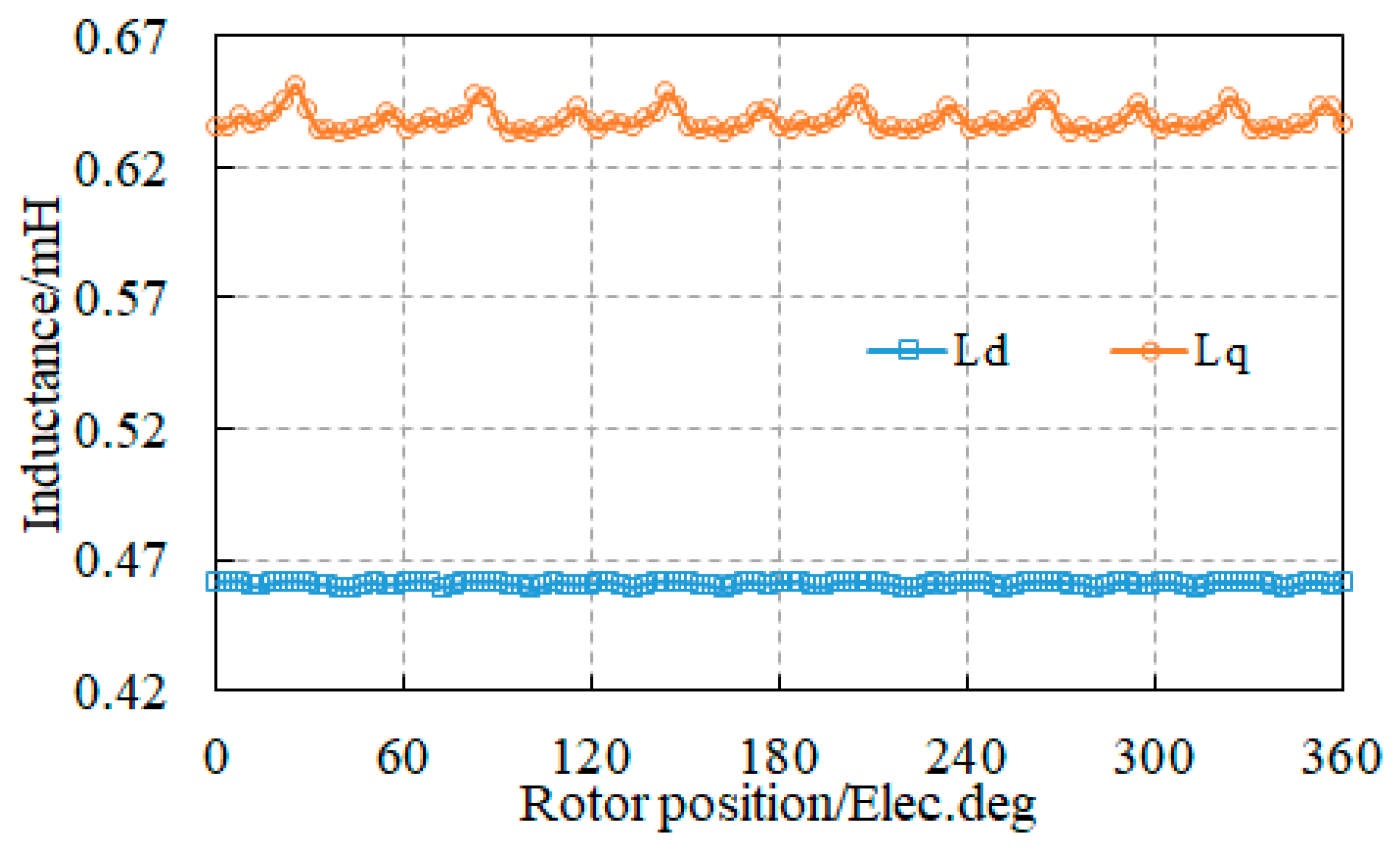
In Figure 2 and Figure 3, the self-inductance and mutual inductance waveforms of the motor model under rated operating conditions, as well as the d-axis and q-axis inductance waveforms, are presented. From the graph, it can be seen that the effective value of self-inductance is 0.7 Wb, and the effective value of mutual inductance is −0.1 Wb. Due to the structural characteristics of the built-in permanent magnet motor, the q-axis inductance value is much greater than the d-axis inductance value.
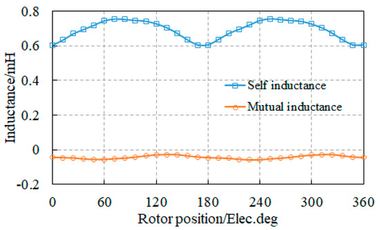
Figure 2.
Self-inductance and mutual inductance waveforms.
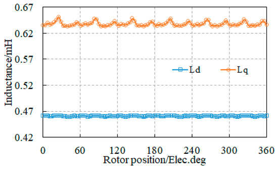
Figure 3.
Waveform diagrams of d-axis inductance and q-axis inductance.
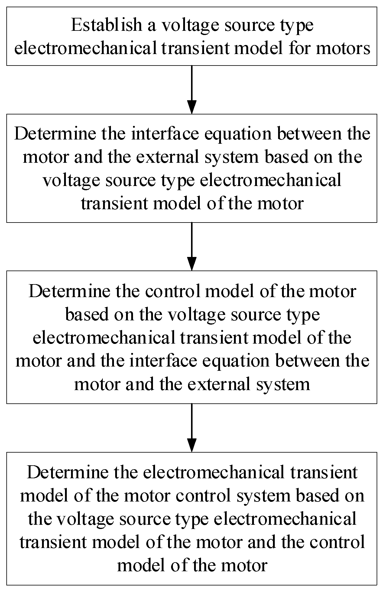
For the establishment of the transient system model of the motor, the first step is to establish the voltage source electromechanical transient model of the motor. Then, based on the voltage source electromechanical transient model of the motor, the interface equation between the motor and the external system is determined. Then, based on the voltage source electromechanical transient model of the motor and the interface equation between the motor and the external system, the control model of the motor is determined. Finally, based on the voltage source electromechanical transient model and the motor control model of the motor, the electromechanical transient model in the motor control system is determined. The transient system modeling flowchart for motors is shown in Figure 4.
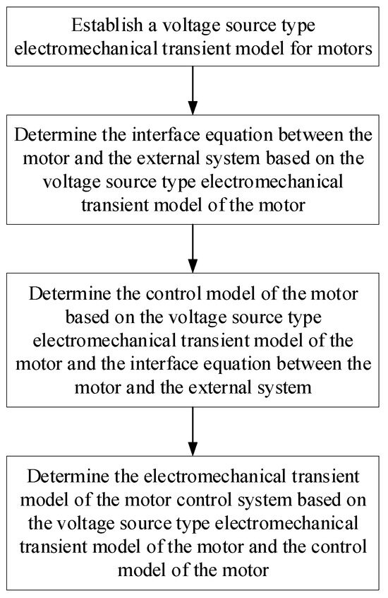
Figure 4.
Transient system modeling flowchart for electric motors.
For the identification of motor faults, the fault recognition system needs to be initialized first, followed by the collection of voltage and current data from the motor. Based on the collected voltage and current data, the power at this time is calculated in real time. Then, the motor operating conditions are filtered according to the calculated power, and whether the data is in a steady state is determined. If the data is in a steady state, the time domain method is used to extract feature vectors. If the data is transient, the frequency domain method is used to extract feature vectors. Subsequently, the probabilities of various fault categories are calculated based on the feature vectors, and the diagnostic results are finally output. The fault identification process diagram is shown in Figure 5.
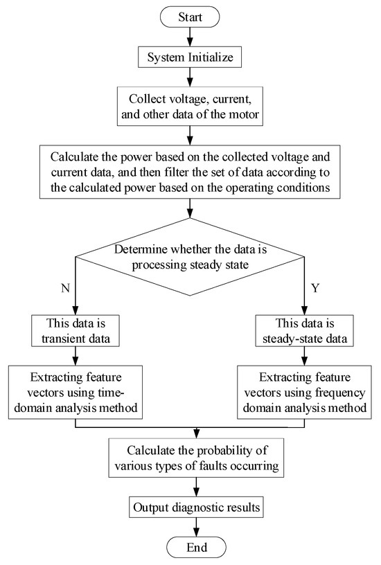
Figure 5.
Motor fault identification flowchart.
To gauge the PMSM’s performance, these methods are frequently employed:
- Acceleration via a specified ramp, managed by a loading apparatus;
- Engagement at various operational junctures, including peak velocity in the area of field weakening, foundational speed at peak torque, and so on;
- Use as a generator when idle.
In the steady processes, the effective values of the currents/voltages and speed of the PMSM are kept constant. The motor operation can be described as:
with the three-phase voltages and phase currents:
and the stator resistance, , also acting as the flux linkage, , per phase (depending on rotor position and currents):
One of the steady state operations is the working point operation, in which the motor is operated at the three working points shown in Figure 6. In Figure 6, M represents torque and N represents speed. The colors in the picture have no practical significance, they are just for the sake of visual appeal.
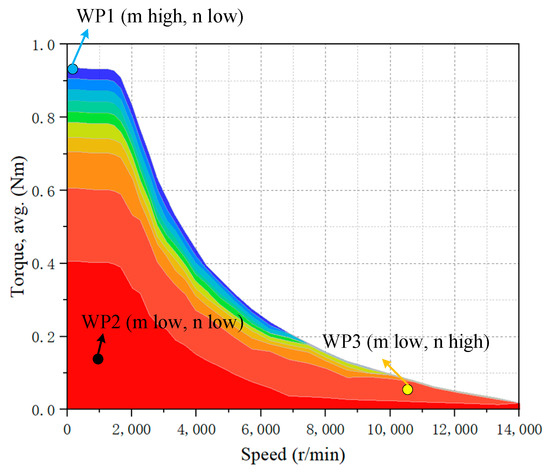
Figure 6.
Working points of a PMSM.
At WP 1, the motor functions at peak torque and reduced speed; WP 3 denotes functioning in the field’s weakening zone at maximum velocity; and WP 2 indicates working at both low speed and torque. Measuring the standard speed area aids in determining efficiency based on rated speed; however, for identifying motor faults, the highest values provide additional clues.
In both scenarios, the motors maintain a steady velocity, making it straightforward to gauge the effective current/voltage and torque. Through the application of these equations, one can determine the electrical power, , mechanical power, , and, additionally, the motor’s efficiency, , at these specific working points. To achieve this, the motor model can be seamlessly converted into a linear format when in a static state. The d–q model, a rotor-focused framework utilizing Park transformation, is extensively employed in PMSMs. The Park transformation streamlines three-phase systems, their equations, and variously measured compounds into a two-dimensional form. The fundamental model of a PMSM can be characterized as:
The definitions of the most important characteristics of the model are given in Table 1. The main parameters of the motor are shown in Table 2.

Table 1.
Definitions of quantities.
Table 2.
Parameters of the studied motor.
Typically, motor malfunctions are identifiable when both the torque applied and the motor’s efficiency fall beyond the acceptable range of the specified value. Employing coordination transformation in a stable state offers the benefit of parameter computation compatibility with the linear regression technique.
An additional constant operation is the idle speed mechanism, where the motor is pulled to a specific velocity, typically the highest, serving as a generator. Electromagnetic induction, detectable in stator windings and known as the voltage constant, serves as an effective metric for identifying motor faults, particularly in assessing PMSM magnet quality.
3. Fault Detection in Transient Processes
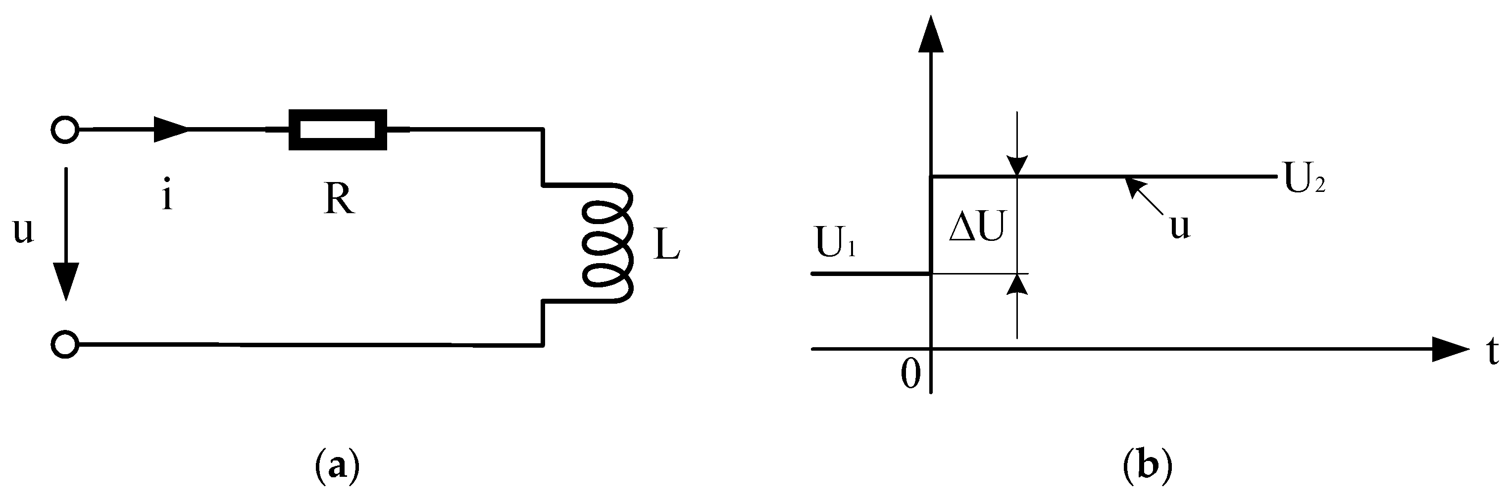
Transient processes take place when a switch is activated within a suitable electrical circuit that includes either a capacitor or an inductor. The element extracts the consequent alterations in voltage or current, requiring a significant duration of time for the system to attain a new equilibrium [7]. In Figure 7, a standard transient current pattern of an R–L circuit is depicted. U1 represents the rated voltage of the motor and U2 represents the peak voltage of the motor.

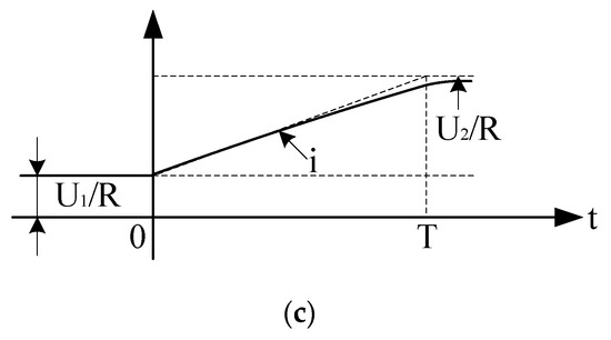
Figure 7.
Typical transient process (a) R–L circuit; (b) voltage pulse; (c) current profile as the step response with the time constant, T.
Transient states in motor functioning arise due to two factors: the rotor’s kinetic energy serving as energy storage and the tri-phase voltage/currents present in the stator’s winding. This document overlooks phenomena like the metal sheet’s hysteresis effect and harmonics.
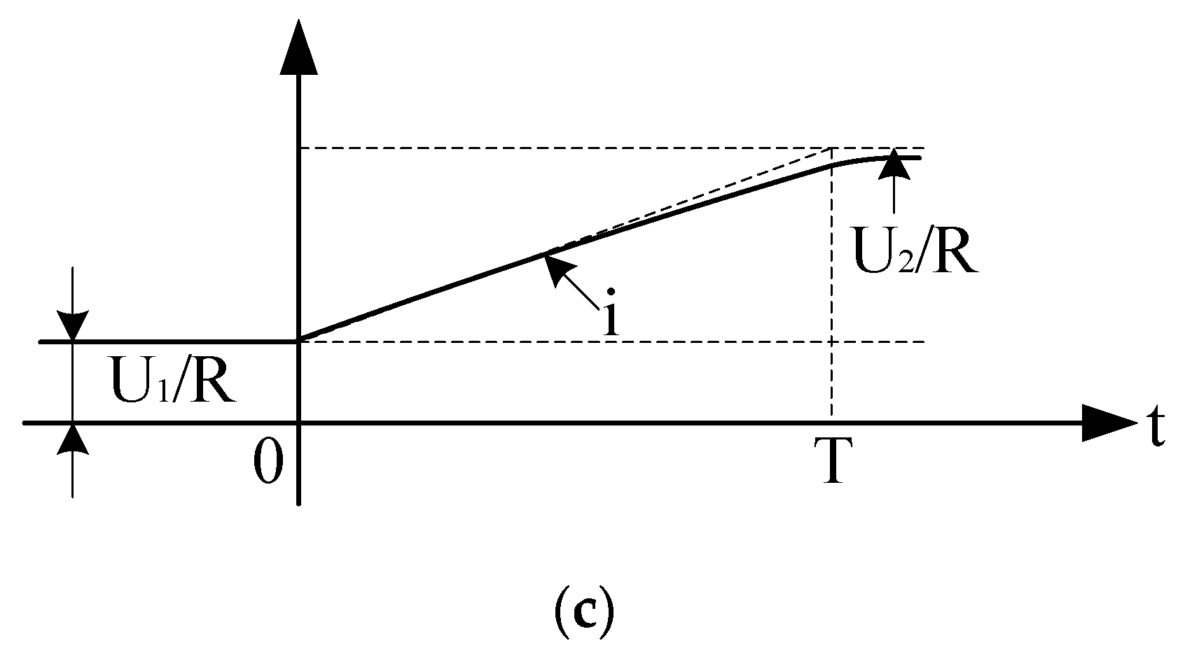
It is possible to categorize these fleeting processes into two distinct phases: transient and sub-transient periods. To illustrate, during a synchronous generator’s short circuit scenario, the recorded current traverses all three states, as depicted in Figure 8. The vertical axis in the figure does not have actual meaning, and the figure is only a schematic diagram of the principles of three transient operating conditions [8].
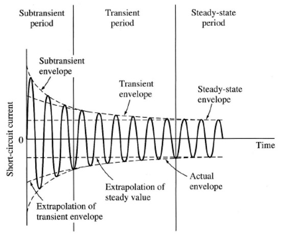
Figure 8.
Sub-transient, transient, and steady-state periods.
The partition of the three periods of the currents here is defined as follows:
- Sub-transient period: the first cycle after the input step. The current is very strong and falls rapidly;
- Transient period: the current falls at a slower rate;
- Steady state: the current reaches its steady value.
By employing digital tools for signal analysis, it is possible to ascertain the time constant, T, during both the sub-transient and transient phases. Consequently, the PMSM’s parameters, like the motor’s reactance along the d and q axes, can be ascertained using the time constant, T, and the peak/effective values. The subsequent section presents a few experimental configurations for parameter identification. There are two methods to identify motor faults: firstly, contrasting the directly measured parameters with reference parameters and, secondly, computing the indirect parameters and aligning them with the design values. Each technique comes with its own set of pros and cons.
3.1. Transient Processes in PMSMs at Quasi-Constant Speed
In cases of specific state alterations, the motor may be viewed as maintaining a nearly steady speed, as depicted in ref. [9]. Given that the electrical time constant is significantly less than the mechanical time constant, it is presumed that the speed remains steady for an adequate duration during subsequent dynamic activities:
- Sudden short circuit;
- Step in electrical load (generator operation);
- Switching operation between converter and drive.
The benefit of operating at a quasi-constant speed lies in the disappearance of the speed’s derivative components in mechanical formulas, allowing for their further simplification. The given mechanical Equation (12) can be reformulated as follows. The torque generated electrically matches that of the load torque.
In the next sections, test setups with transient processes for estimation of the motor parameters and fault detection are further detailed.
3.1.1. Sudden Short Circuit
There are different publications, such as refs. [10,11], on sudden short circuits with or without initial current. For burst short circuit testing, the connection settings are shown in Figure 9. First, the motor operates at a rated speed with a rated voltage of 10%. Then, the main circuit breaker is opened to protect the inverter and the SC circuit breaker is closed. The switching time must be brief so that the motor remains in a subtransient phase.

Figure 9.
Test setup for a sudden short circuit.
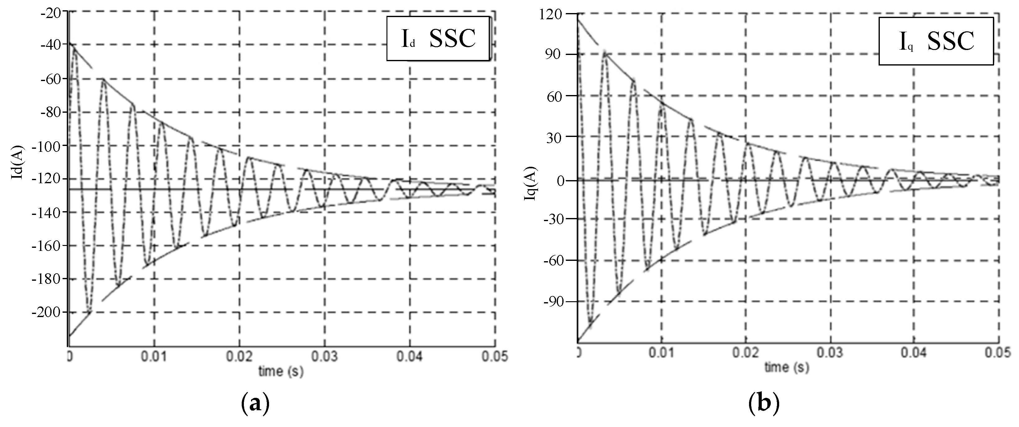
The resulting sudden short circuit (in short SSC) currents from the simulation in d–q coordinates are shown in Figure 10.
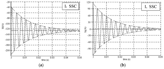
Figure 10.
Currents in d–q coordinates for sudden short circuits. (a) Currents in d coordinates; (b) Currents in q coordinates.
In the short circuit case, the voltage in the motor can be considered zero:
To solve the differential Equations (4)–(12) with numerical methods such as Gauss or Runge–Kutta in the time domain, the equations must be in the form:
where is the Id and Iq of the current, A is the system matrix, B is the disturbance input matrix, C is any constant, and x is the disturbance. Equations (4)–(7) can be transformed into the following equations:
In matrix form, they appear as follows:
Using Equations (14) and (18), this can be simplified to:
In case of a stationary short circuit, the equations can be solved with:
In a sudden short circuit case, the synchronous reactance, Xd, the transient reactance, Xd′, the sub-transient reactance, Xd″, the transient short circuit time constant, td′, and the sub-transient short circuit time constant, td″, are calculated and used for the detection of motor faults, as in ref. [12].
Here, i(t) is the short circuit current, U is the voltage before the short circuit, in this case, 10% of UN.
By subtracting the first term and drawing the remaining term on a half-log sheet as a function of time, the curve can be divided into two parts: the rapidly decaying part is the subtransient portion and the straight line is the transient portion [13].
The transient reactance as a percentage can be calculated with the following equations:
where Ueff and Ieff are the effective values of voltage and currents and Ik, Ik’, and Ik’’ are the component currents read from the semi-log sheet. Zs is the synchronous impedance of the machine at rated voltages and currents. SCR is the short circuit ratio of the machine and Ifoc and Ifsc are the field currents for rated voltages and currents.
Comparing the calculated inductances with the inductance in the design sheets, the winding fault, air gap fault, and magnet quality of the motor can be detected.
3.1.2. Startup With no Load and Zero Currents
There are different ways to start a PMSM motor from a static state [14]. In this paper, the constant current of Id and Iq is fed into the motor, and the DC control is started. At startup, the motor first runs a subtransient cycle, as shown in Figure 11.
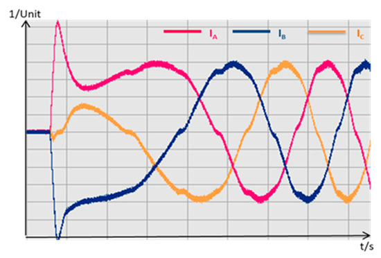
Figure 11.
Startup currents in three three-phase systems.
The first peak of the currents here obviously follows the rule:
By measuring the peak values of the currents, it can be determined whether the winding of the stators has inter-turn faults.
3.1.3. Switching in Converter
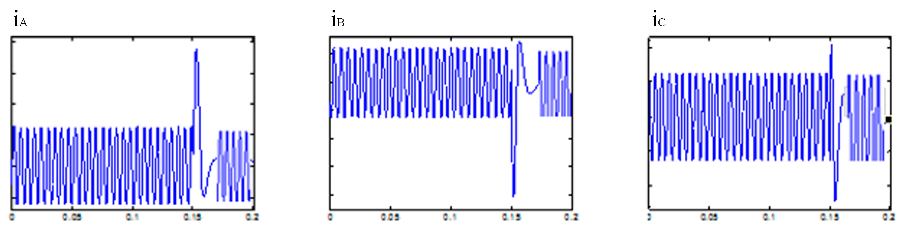
For instance, this situation is executed by altering the sequence in which input lines A, B, and C are being operated. This alteration causes the motor to abruptly change its direction of rotation and undergo processes that are both sub-transient and transient before stabilizing. This technique offers dual benefits: firstly, it enables an abrupt alteration in the inverter drive; secondly, it allows the rotor’s inertia to act as an additional burden on the motor, even in the absence of an external load. The procedure bears resemblance to the short circuit test, as evidenced by the simulation outcomes depicted in Figure 12.

Figure 12.
Currents in the three-phase system for a converter switch.
In this scenario, fault analysis is guided by two key metrics: firstly, the highest current value during each phase; secondly, the inductances for both sub-transient and transient processes, taking into account the diminishing time (in relation to the inductances’ intended values). These formulas align with those previously outlined in the context of short circuit scenarios.
3.2. Transient Process of PMSM in Non-Constant Speed Operation
Additional examination of dynamic operations was conducted due to the quasi-constant speed method exerting stress on both the tested motor and the converter unit. As an illustration, an abrupt shift in the direction of rotation may lead to harm to both the bearings and the rotor’s lamination. Within certain motor configurations, an abrupt short-circuit may lead to harm to the winding’s isolation. Consequently, additional dynamic mechanisms are implemented; during acceleration and deceleration, various parameters are measurable and computable. Motor malfunctions are identifiable based on the selected parameters [15].
3.2.1. Acceleration
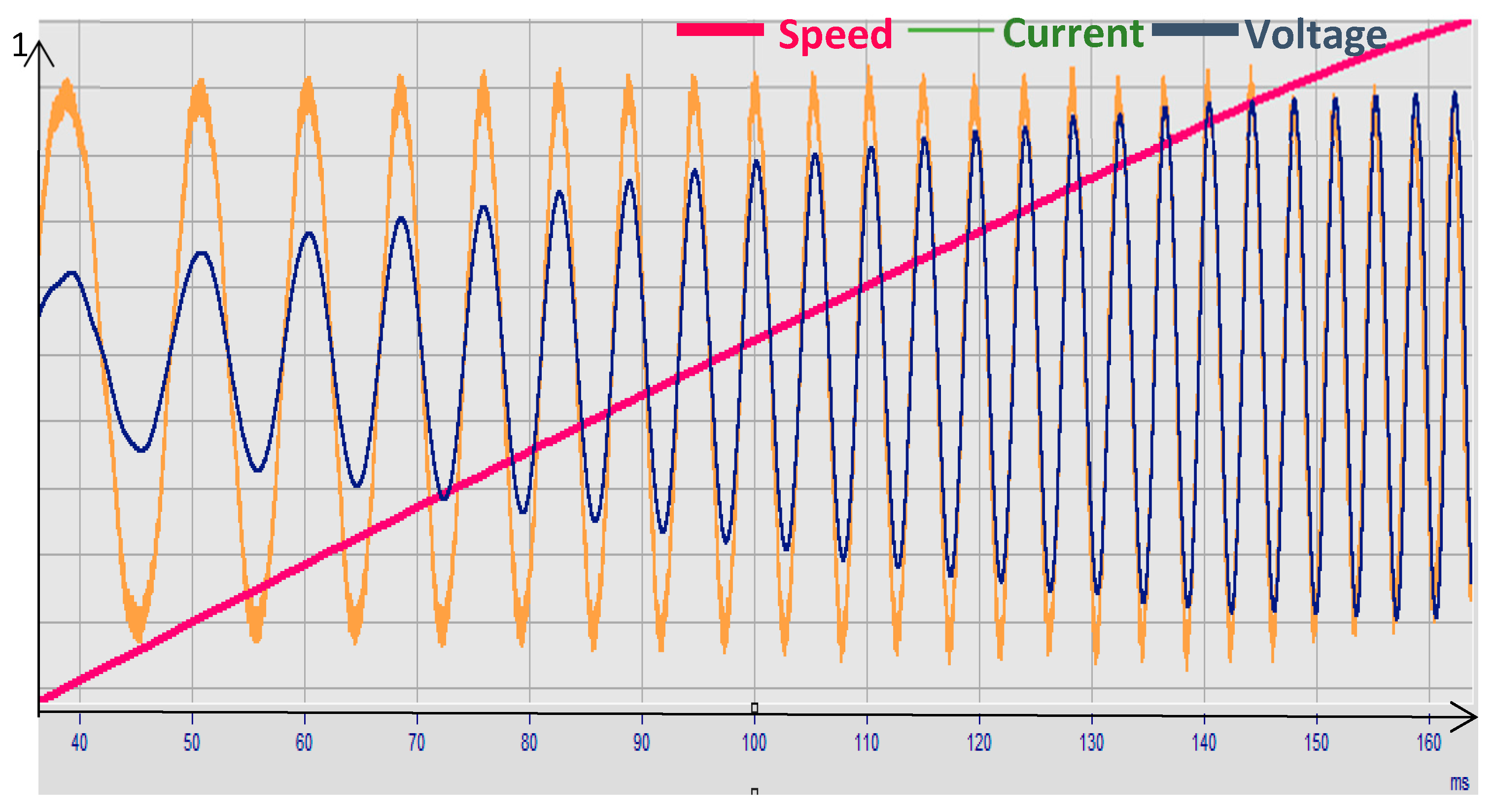
Various methods exist to speed up the motor. This document details how the motor’s acceleration occurs through steady amplitude currents. During the acceleration phase, following the sub-transient phase, and prior to the motor attaining a steady speed, both current and voltage remain in a temporary state, as depicted in Figure 13. During this time frame, the three-phase voltage’s amplitude increases, whereas the current’s amplitude stays steady thanks to the controller. Speed increases linearly.
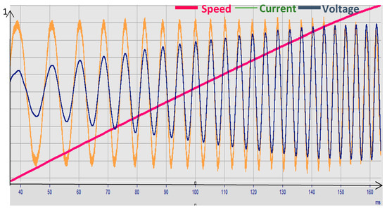
Figure 13.
Speed and UA, IA during the whole acceleration period.
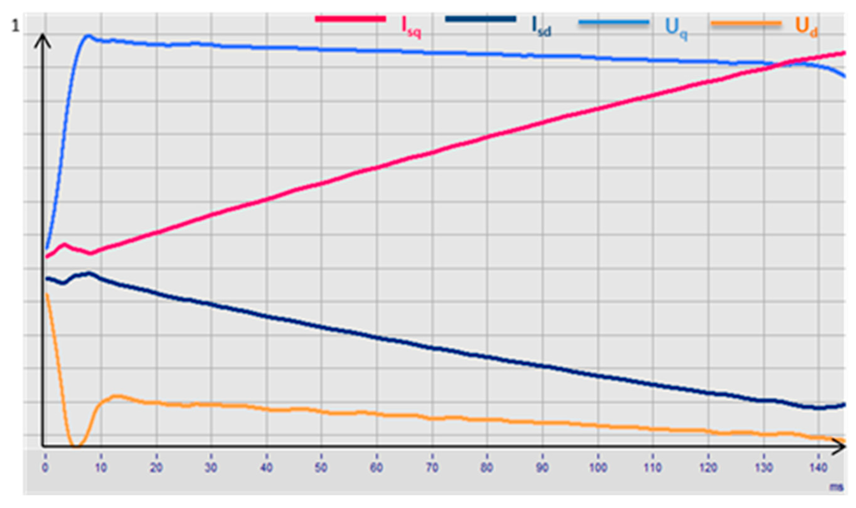
The precision in pinpointing parameters through signals across three phases heavily relies on how the signals are processed. From one perspective, one can examine the amplitude envelope of rising/sinking and contrast it with the reference points. An alternative approach begins with the Park transformation, moving the tri-phase voltages/currents through a dual-phase system, as illustrated in Figure 14.

Figure 14.
Ud, Uq, Id, and Iq during the whole acceleration period.
It can be seen that the current and voltage signals have a more linear behavior, which makes the calculation of the instantaneous values at a certain speed much easier. Equations (4) and (5) can be transformed in the following form:
with
Using Equation (23), the inductances of the motor can be calculated. With parameter analysis tools, the motor fault (such as eccentricity or magnet fault) can be detected based on motor inductances as shown in refs. [16,17,18].
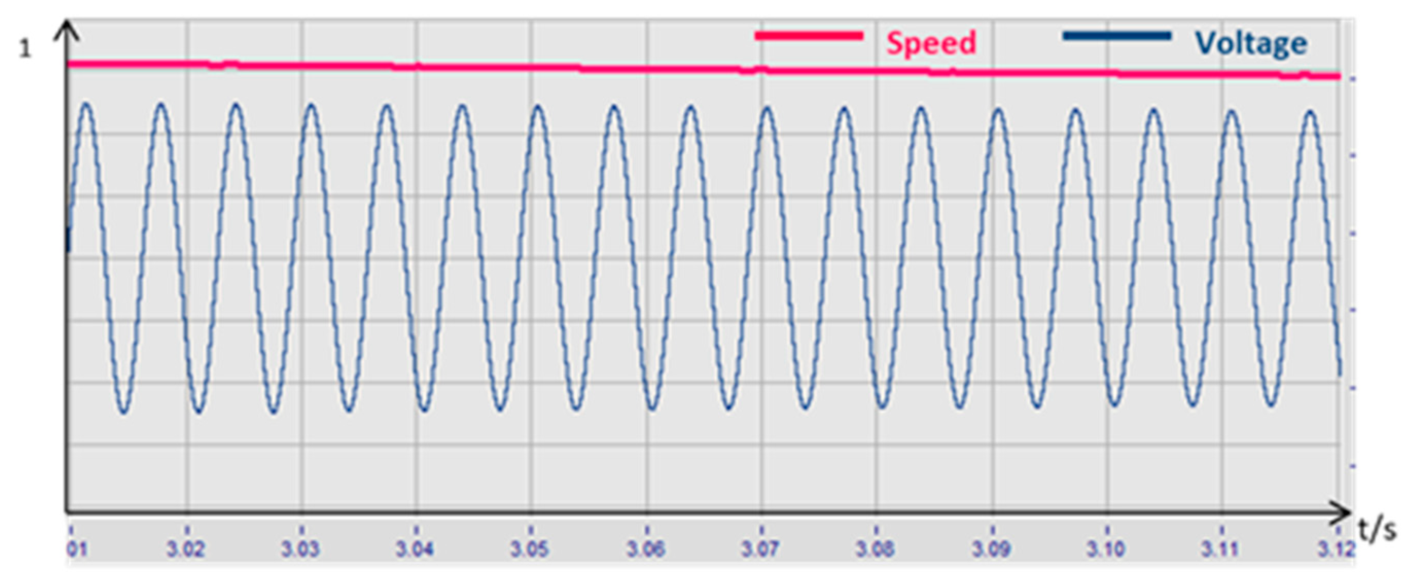
3.2.2. No-Load Run-Down
In the run-down period with the unloaded machine, the motor slows down only depending on the friction and cogging torque. A sample of measured values for phase voltage and speed is displayed in Figure 15.
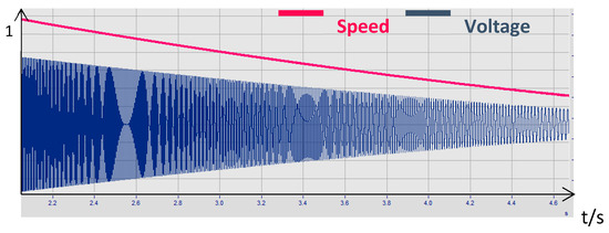
Figure 15.
Speed and voltage U1 during the whole run-down period.
Given that the run-down procedure mirrors the generator’s function, the sole distinction lies in the absence of any external mechanical force. Thus, the magnitudes of the generated voltage and rotational velocity steadily diminish [3,19]. In contrast to static operations at idle speed, determining the motor voltage constant requires the use of a transient analysis instrument. In Figure 16, a brief phase (10 ms) is depicted during the run-down, characterized by voltage U1 and velocity.
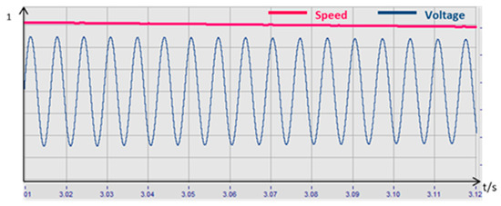
Figure 16.
Speed and voltage UA in a short run-down period.
Based on the short interval, the voltage constant, , is calculated from the phase voltage amplitude divided by the speed:
During the run-down phase, two methods exist for determining the voltage constant: the initial approach involves identifying the peak value envelope in the voltage signal and dividing it by the velocity. It is possible to compute and provide the average values for the entire sequence. An alternative approach involves applying an equation to estimate the left section in relation to the observed voltage signal [20]:
In both methods, can be used to detect motor faults such as unstable magnet quality or air gap tolerances.
4. Conclusions
This article introduces various techniques for pinpointing parameters and configuring tests for fault analysis in PMSMs, utilizing signals from temporary processes. Relative to static techniques, this method demands less time and less precise motor control. Utilizing a loading machine is also unnecessary, leading to decreased time spent on connections and lower hardware costs. Clearly, capturing signals during brief and fleeting intervals necessitates more precise and efficient measuring tools, and the system also demands considerable data analysis efforts. With contemporary DSP technology, the latter presents a controllable difficulty.
Various transient techniques often rely solely on direct, quantifiable metrics like voltages and currents, facilitating easy comparison with their benchmark values. Nonetheless, acquiring essential values like inductances necessitates computational or transformational methods. Essentially, contrasting those indirect figures with a benchmark metric is adequate, and for enhanced dependability, it is recommended to create these benchmarks through the simulation of design variables. Given that tolerances are usually established in the design sheet, motor faults are not overlooked during the final line test.
In future electric vehicle industry, there will be higher requirements for the accuracy and speed of motor fault diagnosis. Only through collecting and analyzing the fault information generated when the motor is in a fault state and timely warning or effective cutting off of the fault source can the protection of the motor and the safety of the entire vehicle be guaranteed. Therefore, motor fault diagnosis will appear in all-electric vehicles to ensure their safety; not only will this be applied in electric vehicles, but also in emerging industries such as aerospace, military enterprises, and intelligent robots.
Author Contributions
Conceptualization, C.W.; methodology, C.W.; software, C.W.; validation, C.W.; formal analysis, C.W.; investigation, C.W.; resources, C.W.; data curation, C.W.; writing—original draft preparation, C.W.; writing—review and editing, C.W.; visualization, A.V.; supervision, A.V.; project administration, A.V.; funding acquisition, A.V. All authors have read and agreed to the published version of the manuscript.
Funding
This research received no external funding.
Data Availability Statement
The original contributions presented in the study are included in the article, further inquiries can be directed to the corresponding author.
Conflicts of Interest
The authors declare no conflicts of interest.
References
- Liang, J.; Feng, J.; Fang, Z.; Lu, Y.; Yin, G.; Mao, X.; Wu, J.; Wang, F. An energy-oriented torque-vector control framework for distributed drive electric vehicles. IEEE Trans. Transp. Electrif. 2023, 9, 4014–4031. [Google Scholar] [CrossRef]
- Liang, J.; Wang, F.; Feng, J.; Zhao, M.; Fang, R.; Pi, D.; Yin, G. A Hierarchical Control of Independently Driven Electric Vehicles Considering Handling Stability and Energy Conservation. IEEE Trans. Intell. Veh. 2023, 9, 738–751. [Google Scholar] [CrossRef]
- Kim, K.T.; Lee, Y.S.; Hur, J. Transient analysis of irreversible demagnetization of permanent-magnet brushless DC motor with interturn fault under the operating state. IEEE Trans. Ind. Appl. 2014, 50, 3357–3364. [Google Scholar] [CrossRef]
- Rodriguez-Blanco, M.A.; Vazquez-Perez, A.; Hernandez-Gonzalez, L.; Pech-Carbonell, A.; May-Alarcon, M. IGBT fault diagnosis using adaptive thresholds during the turn-on transient. In Proceedings of the 2013 9th IEEE International Symposium on Diagnostics for Electric Machines, Power Electronics and Drives (SDEMPED), Valencia, Spain, 27–30 August 2013; IEEE: Piscataway, NJ, USA, 2013. [Google Scholar]
- Pons-Llinares, J.; Antonino-Daviu, J.; Riera-Guasp, M.; Lee, S.B.; Kang, T.-J.; Yang, C. Use of discrete and optimized continuous TFD tools for transient-based diagnosis in controversial fault cases. In Proceedings of the 2013 9th IEEE International Symposium on Diagnostics for Electric Machines, Power Electronics and Drives (SDEMPE), Valencia, Spain, 27–30 August 2013; IEEE: Piscataway, NJ, USA, 2013. [Google Scholar]
- Douglas, H.; Pillay, P.; Ziarani, A. A new algorithm for transient motor current signature analysis using wavelets. IEEE Trans. Ind. Appl. 2004, 40, 1361–1368. [Google Scholar] [CrossRef]
- Qian, H.; Hu, X.; Qin, W.; Zhang, Q.; Zheng, C. Short faults in permanent magnet synchronous machine with variable flux hybrid rotor. In Proceedings of the 2019 22nd International Conference on Electrical Machines and Systems (ICEMS), Harbin, China, 11–14 August 2019; IEEE: Piscataway, NJ, USA, 2019. [Google Scholar]
- Alvarez-Gonzalez, F.; Griffo, A.; Wang, B. Permanent magnet synchronous machines inter-turn short circuit fault detection by means of model-based residual analysis. In Proceedings of the IECON 2018—44th Annual Conference of the IEEE Industrial Electronics Society, Washington, DC, USA, 21–23 October 2018; IEEE: Piscataway, NJ, USA, 2018. [Google Scholar]
- Eilenberger, A.; Schrodl, M. Sudden short-circuit analysis of a salient permanent magnet synchronous machine with buried magnets for traction applications. In Proceedings of the 2010 14th International Power Electronics and Motion Control Conference (EPE/PEMC 2010), Ohrid, North Macedonia, 6–8 September 2010; IEEE: Piscataway, NJ, USA, 2010. [Google Scholar]
- Klontz, K.W.; Miller, T.J.E.; McGilp, M.I.; Karmaker, H.; Zhong, P. Short-circuit analysis of permanent-magnet generators. IEEE Trans. Ind. Appl. 2011, 47, 1670–1680. [Google Scholar] [CrossRef]
- Boglietti, A.; Cavagnino, A.; Cossale, M.; Tenconi, A.; Vaschetto, S. Efficiency determination of converter-fed induction motors: Waiting for the IEC 60034–2–3 standard. In Proceedings of the 2013 IEEE Energy Conversion Congress and Exposition, Denver, CO, USA, 15–19 September 2013; IEEE: Piscataway, NJ, USA, 2013. [Google Scholar]
- Feng, G.; Lai, C.; Li, W.; Tjong, J.; Kar, N.C. Open-phase fault modeling and optimized fault-tolerant control of dual three-phase permanent magnet synchronous machines. IEEE Trans. Power Electron. 2019, 34, 11116–11127. [Google Scholar] [CrossRef]
- Song, Z.; Jia, Y.; Liu, C. Open-phase fault-tolerant control strategy for dual three-phase permanent magnet synchronous machines without controller reconfiguration and fault detection. IEEE Trans. Power Electron. 2022, 38, 789–802. [Google Scholar] [CrossRef]
- Feng, G.; Lai, C.; Li, W.; Han, Y.; Kar, N.C. Computation-efficient solution to open-phase fault tolerant control of dual three-phase interior PMSMs with maximized torque and minimized ripple. IEEE Trans. Power Electron. 2020, 36, 4488–4499. [Google Scholar] [CrossRef]
- Wang, X.; Wang, Z.; Gu, M.; Wang, B.; Wang, W.; Cheng, M. Current optimization-based fault-tolerant control of standard three-phase PMSM drives. IEEE Trans. Energy Convers. 2020, 36, 1023–1035. [Google Scholar] [CrossRef]
- Chai, F.; Gao, L.; Yu, Y.; Liu, Y. Fault-tolerant control of modular permanent magnet synchronous motor under open-circuit faults. IEEE Access 2019, 7, 154008–154017. [Google Scholar] [CrossRef]
- Liu, L.; Cartes, D. Synchronisation based adaptive parameter identification for permanent magnet synchronous motors. IET Control Theory Appl. 2007, 1, 1015–1022. [Google Scholar] [CrossRef]
- Ishikawa, T.; Seki, Y.; Kurita, N. Analysis for fault detection of vector-controlled permanent magnet synchronous motor with permanent magnet defect. IEEE Trans. Magn. 2013, 49, 2331–2334. [Google Scholar] [CrossRef]
- Rao, Y.; Wang, Y.; Wang, W. A Simplified Modeling and Analysis Method for Interturn Short-Circuit Fault of Permanent Magnet Synchronous Motor. In Proceedings of the 2023 26th International Conference on Electrical Machines and Systems (ICEMS), Zhuhai, China, 5–8 November 2023; IEEE: Piscataway, NJ, USA, 2023. [Google Scholar]
- Dogan, Z.; Tetik, K. Diagnosis of inter-turn faults based on fault harmonic component tracking in LSPMSMS working under nonstationary conditions. IEEE Access 2021, 9, 92101–92112. [Google Scholar] [CrossRef]
Disclaimer/Publisher’s Note: The statements, opinions, and data contained in all publications are solely those of the individual author(s) and contributor(s) and not of MDPI and/or the editor(s). MDPI and/or the editor(s) disclaim responsibility for any injury to people or property resulting from any ideas, methods, instructions, or products referred to in the content. |


Disclaimer/Publisher’s Note: The statements, opinions and data contained in all publications are solely those of the individual author(s) and contributor(s) and not of MDPI and/or the editor(s). MDPI and/or the editor(s) disclaim responsibility for any injury to people or property resulting from any ideas, methods, instructions or products referred to in the content. |
© 2024 by the authors. Licensee MDPI, Basel, Switzerland. This article is an open access article distributed under the terms and conditions of the Creative Commons Attribution (CC BY) license (https://creativecommons.org/licenses/by/4.0/).