Article

Analysis and Suppression of Spoke-Type Permanent Magnet Machines Cogging Torque with Different Conditions for Electric Vehicles

1
School of Electrical Engineering Anhui Technical College of Mechanical and Electrical Engineering, Wuhu 241002, China
2
School of Electrical Engineering Anhui Polytechnic University, Wuhu 241000, China
*
Author to whom correspondence should be addressed.
World Electr. Veh. J. 2024, 15(8), 376; https://doi.org/10.3390/wevj15080376
Submission received: 2 July 2024 / Revised: 30 July 2024 / Accepted: 13 August 2024 / Published: 19 August 2024

Abstract

:
Spoke-type permanent magnet (STPM) machines have high power density and low cost due to flux concentrated effect and high air-gap flux density, but they can cause high cogging torque and torque ripple. To reduce the cogging torque, the analytical model considering a rotor slot is established and compared with the finite element mothed (FEM). Then, the cogging torque production mechanism is revealed and analyzed under different conditions, which provides direction to optimize the cogging torque STPM machines. The harmonic content of cogging torque under different conditions is obtained based on the freezing permeability (FP) method. It is found that the fundamental waves mainly generate the cogging torque under a no-load condition, and it is mainly generated by the second harmonics under an on-load condition. In addition, the optimization method is introduced and researched, including rotor slot width, uneven rotor core, and so on. Finally, a 50 kW STPM machine prototype is manufactured and tested to verify the accuracy and efficiency of the analysis method.

1. Introduction

In recent years, electric vehicles (EVs) have gradually replaced traditional vehicles and have become the main development direction for transforming and upgrading the vehicle industry [1,2,3]. The broad application of EVs has put higher requirements on the high efficiency and power density of driving systems. As a key core component, the high power density and efficiency of drive motors have become an inevitable tendency. Compared with other structures, permanent magnet (PM) machines are considered the ideal choice due to their higher efficiency, higher power density, and simple rotor structure [4,5].
To further improve the power density, the spoke-type PM (STPM) machines are regarded as excellent candidates due to their flux concentration [6,7]. Due to the STPM machine having the advantage of high torque density, it can be applied in a Formula E racing car [8]. In reference [9], a new STPM machine is designed and optimized to come up with designs targeting traction applications using various grades of Dy-free magnets. Four different magnetic composite (SMC) rotor topologies with STPM machines are designed and compared, and the results showed that the SMC rotor has lower cost and higher efficiency compared with laminated rotor machines [10]. To improve the flux weakening capability and reduce torque ripple, some optimization methods are adopted for STPM machines [11,12]. Obviously, most of the work has been done to propose novel rotor topology and optimized electromagnetic performance for STPM machines, but it does not discuss cogging torque. Although the STPM machines can improve the power density, they also introduce the problems of high cogging torque due to their high air-gap flux density, which causes potential high vibration and noise. Vibration and noise are key points of EV driving systems, which reduce comfort and destroy the road surface.
Cogging torque is one of the important particular features of PM machines, which is produced by PMs and stator slotting iron-core. Compared with others PM machines, STPM machines have a higher air-gap flux density due to magnetism gathering, which creates a high cogging torque. The problem of vibration and noise is more serious than in other PM machines, and so the cogging torque of STPM machines has become the focal point of research for scholars and experts. In [13], the variation in cogging torque caused by manufacturing tolerances for STPM machine was studied and analyzed. A sinusoidal PM-shaping method was proposed to reduce the cogging torque of STPM machine, and the 3-D FE model was built to verify the proposed method [14]. In addition, a novel multistep design and optimization strategy to minimize cogging torque and torque pulsations in STPM motor with phase-group concentrated-coil windings was studied [15]. To reduce the cogging torque of STPM machines, a novel asymmetric spoke-type rotor was proposed, and compared with conventional IPM machines, a prototype was manufactured and tested to verify the electromagnetic performance of the proposed machine [16].
On the whole, the cogging torque of STPM machines has been analyzed and researched, but this has been concentrated on no-load conditions. However, the STPM machines usually work under on-load conditions for EV driving systems, and the cogging torque can be obviously influenced by magnetic saturation. The contribution of this paper can be listed as follows: (1) The analytical model of cogging torque for the STPM machine is built by considering the rotor slot, which provides a new method to reduce the cogging torque. (2) The effect of harmonic on cogging torque is studied and revealed under different conditions based on the freezing permeability (FP) method. (3) Three cogging torque suppression methods are introduced to reduce the no-load and on-load cogging torque for STPM machines for EV application.
This article is organized as follow: The cogging torque analytical model of STPM machines is established to introduce the rotor slotting, and the key parameters are obtained to suppress cogging torque in Section 2. Then, the influences mechanism of cogging torque harmonic content is studied and analyzed. In Section 3, to reduce the cogging torque the rotor slotting width, uneven rotor core, uneven stator core, and stator auxiliary slotting were analyzed. In Section 4, the analysis method and results are validated by a 50 kW prototype and experimental results.

2. Theoretical Analysis of Cogging Torque

2.1. Machine Topology

Figure 1 shows the configuration of the designed STPM machine, and the key parameters are listed in Table 1. The 12-slots–10-pole combination is designed by considering the switching frequency for the PM machine controllers. In addition, the outer diameter is fixed to 180 mm, and the stack length is also fixed to 180 mm due to the size limitation. It can be seen that rotor slotting is adopted to enhance the rotor’s mechanical strength, which leads to the cogging torque being different from that of traditional PM machines. The cogging torque is higher than that of surface-mount PM machines due to high air-gap flux density. Then, the water-cooling method is applied to improve the power density, and the current density is about 8 A/mm2 in this paper.

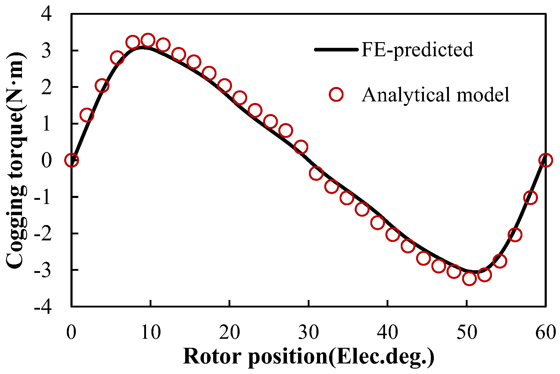
2.2. Analytical Model of Cogging Torque

Compared with the traditional PM machine, the stator and rotor of the STPM machine are slotted on both sides. In addition, the distribution of the air-gap flux density can be obtained as
B 2 ( θ , α ) = B 0 b P M ( θ , α ) Λ 01 λ 1 ( θ ) Λ 02 λ 2 ( θ , α )
where bPM(θ,α) is the distribution of air-gap flux density by PM, B0 is the air-gap flux density without slots, λ1(θ) is the distribution of relative air-gap permeability with stator slot, λ2(θ,α) is the distribution of relative air-gap permeability with a rotor slot, Λ01 is the ratio of λ1(θ) and Λ1(θ) amplitude, and Λ02 is the ratio of λ2(θ) and Λ2(θ) amplitude.
For STPM machines, bPM(θ,α) can be followed by [17],
b P M ( θ , α ) = m = 1 b m cos m p ( θ α )
where m is the number of harmonic order, bm is the amplitude of the mth harmonic, and p is the pole pair number
Then, λ1(θ) can be obtained as [18]
λ 1 ( θ ) = λ 10 + μ 1 = 1 λ μ 1 cos μ 1 Q 1 ( θ π Q 1 )
where Q1 is the number of stator slot; λ10 and λμ1 are the Fourier decomposition coefficient, which can be obtained as
λ 10 = 1 1.6 β 1 b 01 τ t 1
λ μ 1 = [ 1 2 1 2 1 + ( B s 0 2 g ) 2 ( 1 + v 1 2 ) ] 4 μ 1 π [ 0.5 + ( μ 1 B s 0 τ t 1 ) 2 0.78125 2 ( μ 1 B s 0 τ t 1 ) 2 ] sin ( 1.6 π μ 1 B s 0 τ t 1 )
where τt1 is the stator pole pitch, Bs0 is the stator slot opening width, g is the air-gap length, μ1 is the stator permeability, and v1 is obtained by literature [15].
In addition, λ2(θ,α) can be calculated by
λ 2 ( θ , α ) = λ 20 + μ 2 = 1 λ μ 2 cos μ 2 Q 2 ( θ α )
where Q2 is the number of rotor slots, and λ20 and λμ2 are the Fourier decomposition coefficients, respectively, which can be followed as
λ 20 = 1 1.6 β 2 b 02 τ t 2
λ μ 2 = [ 1 2 1 2 1 + ( B s 1 2 g ) 2 ( 1 + v 2 2 ) ] 4 μ 2 π [ 0.5 + ( μ 1 B s 1 τ t 2 ) 2 0.78125 2 ( μ 1 B s 1 τ t 2 ) 2 ] sin ( 1.6 π μ 2 B s 1 τ t 2 )
where τt2 is the rotor pole pitch, Bs1 is the stator slot opening width, and v2 is obtained by literature [15].
τt2 can be followed by
τ t 2 = π D 2 Q 2
where D2 is the rotor outer diameter.
Based on the energy perturbation method, the cogging torque can be followed as
T c o g = W α W a i r g a p α = α [ 1 2 μ 0 V B 2 ( θ , α ) d V ]
where Wairgap is the air-gap energy, θ is the electric angle, α is the angle between the center line of the stator teeth and the PM pole, μ0 is the permeability of air-gap, and B(θ,α) is the air-gap flux density.
Therefore, the air-gap magnetic field energy of STPM machines can be obtained as
W a i r g a p = B 0 2 Λ 01 2 Λ 02 2 L e f p π 2 μ 0 V [ b P M ( θ , α ) λ 2 ( θ , α ) ] 2 λ 1 ( θ ) d V
where Lef is the axial length.
Finally, the cogging torque by considering rotor slotting can be expressed as based on the Maxwell stress tensor method
T c o g = B 0 2 Λ 01 2 Λ 02 2 L e f p π 8 μ 0 ( D i 1 2 D 2 2 ) n = 1 n b n λ 2 n p Q 1 sin 2 n p α
where Di1 is the stator inner diameter.
Figure 2 shows the cogging torque waveforms under a no-load condition between the analytical model and FE predictions. It can be seen that the analytical result agrees well with FE predictions, and the error is mainly from the air-gap field results. The error is less than 9.43%, which verifies the results of the proposed method are very sensitive to the error of the field distribution in this paper. In addition, the amplitude of cogging torque is achieved at about 3.1 N·m, which can cause high vibration and noise.

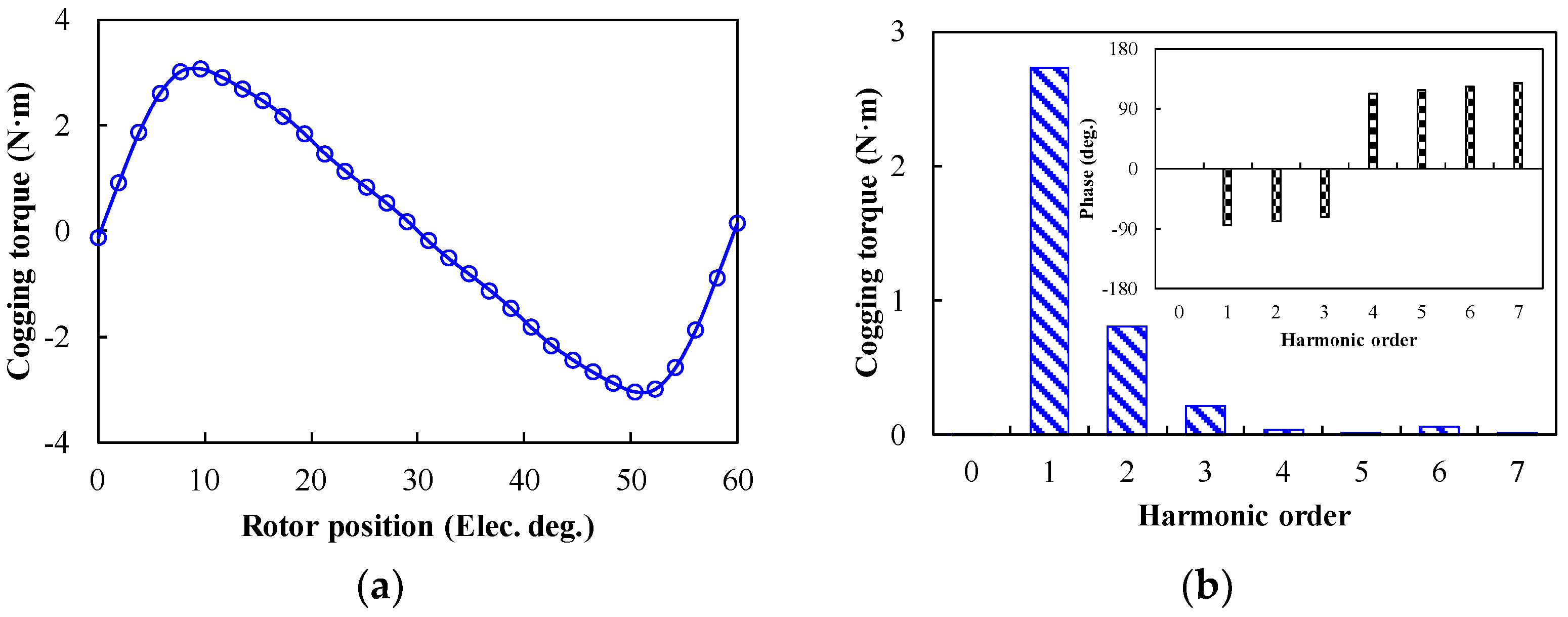
2.3. Harmonics Analysis of Cogging Torque

To reveal the cogging torque production mechanism for the designed STPM machine, the no-load cogging torque and corresponding harmonic spectrum are shown in Figure 3. In addition to the fundamental component (1st), 2nd and 3rd harmonic components also significantly existed. The phases of the 1st, 2nd, and 3rd cogging torque harmonics are opposite to those of other harmonics, which means that the harmonics of other orders have a suppressing effect on the cogging torque.
The cogging torque waveforms under different load conditions based on the FP method are shown in Figure 4a. Condition 1 is the rated torque under 2400 r/min, condition 2 is the peak torque under 500 r/min, and condition 3 is the peak speed at the rated power. It can be seen that the on-load cogging torque is significantly higher than the no-load cogging torque. Then, the cogging torque is increased with the increases in electromagnetic torque due to the magnetic saturation level being increased in the stator core. In addition, the corresponding harmonic analysis of cogging torque under different conditions is shown in Figure 4b. It shows that the 2nd harmonic is the primary harmonic causing the on-load cogging torque in conditions 1 and condition 3, and the 1st and 2nd harmonics are the primary harmonics influencing the no-load cogging torque. However, the actual cogging torque periodicity becomes 60 electrical degrees no matter what the electric loading value is.

3. Suppression of Cogging Torque

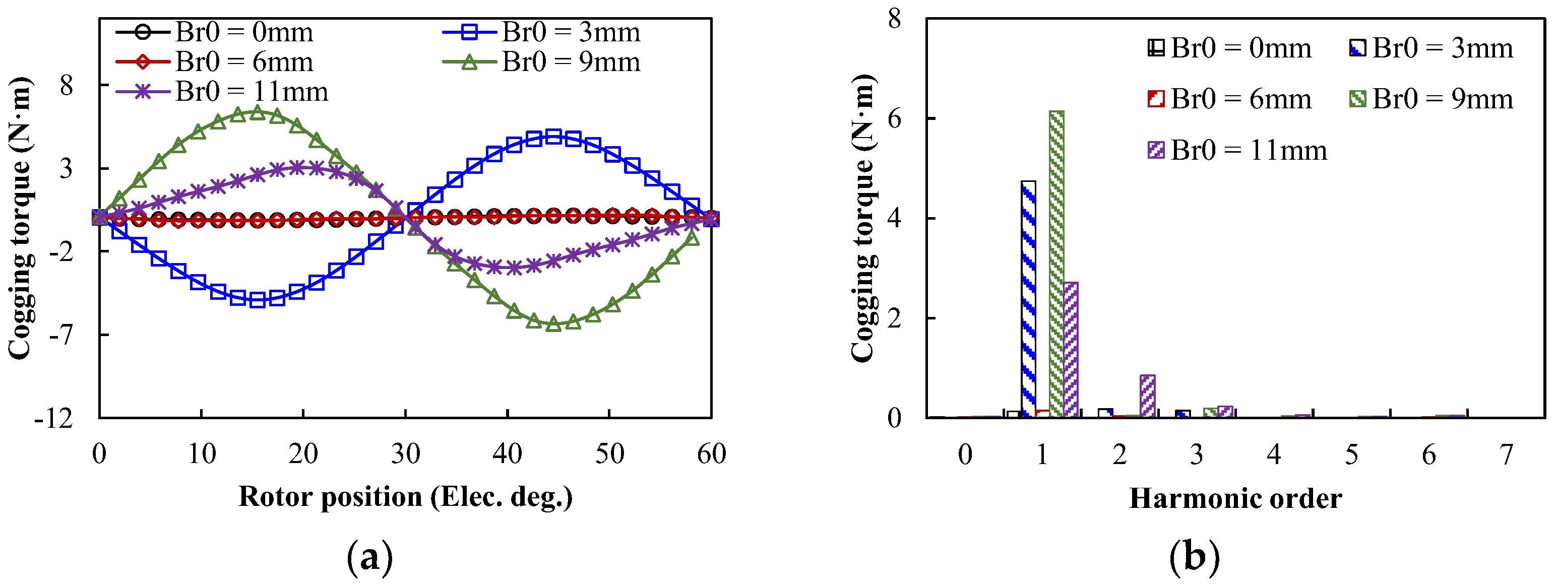
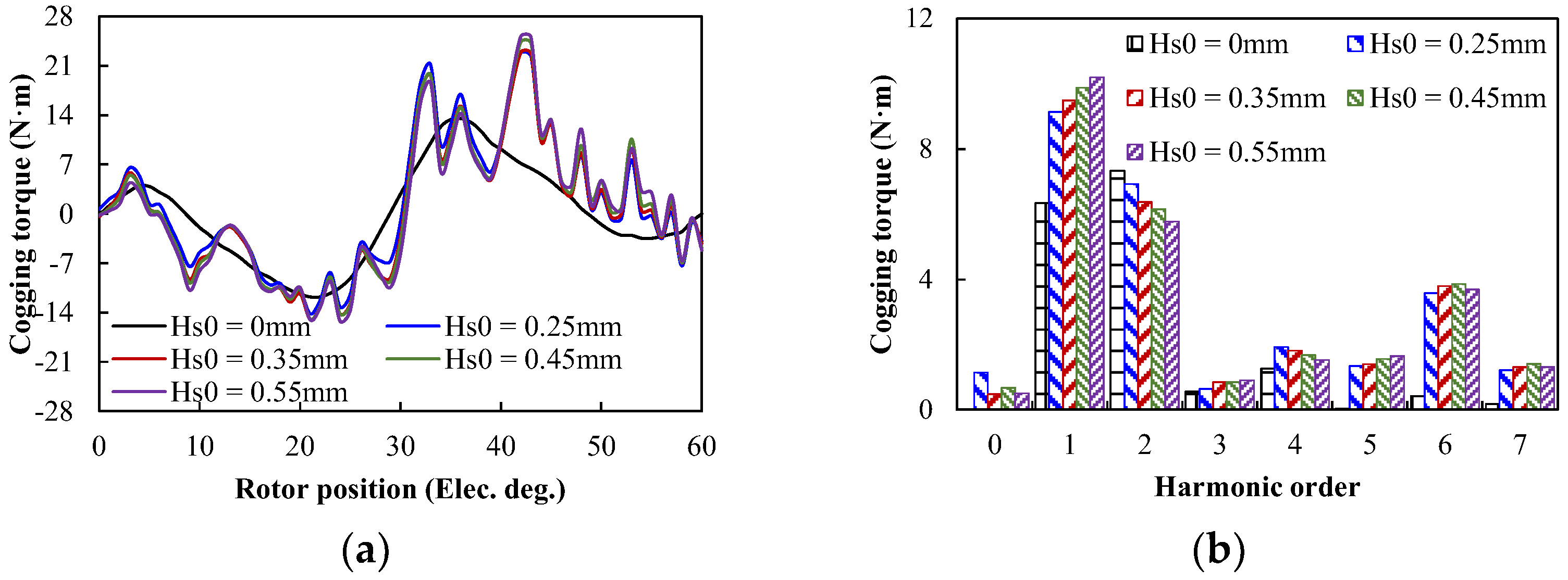
3.1. Rotor Slotting Width

For Formula (11), the traditional reduction method is suitable for suppressing the cogging torque of the STPM machine. Besides this, the cogging torque is influenced by rotor structure parameters for the STPM machine. The Fourier expansion of the magnetomotive force can be expressed as
F 2 ( θ ) = F 0 + n = 1 ( F a n cos 2 n p θ + F b n sin 2 n p θ )
where Fourier coefficient F0 can be obtained as
F 0 = ( Q 2 1 ) p π t r 2 t 2 θ r F 2
where p is rotor pole pairs, tr is rotor pitch, t2 is rotor tooth width, and F is the amplitude of air-gap magnetomotive force.
If the rotor parameters meet the following formula, the cogging torque can be reduced significantly.
n Q 1 2 ( t 2 θ r ) = k π
The variations of cogging torque with different rotor slot width under no-load are shown in Figure 5. It can be seen that the rotor slot width had a certain effect on inhibiting the cogging torque under no-load conditions. The amplitude of the cogging torque was minimum while the rotor slot widths were 0 mm and 6 mm, respectively. The reason is that the cogging torque only affected the stator slot at the 0 mm rotor slot width, and the Formula (14) is satisfied at the 6 mm rotor slot width. At this time, the cogging torques were 0.15 N·m and 0.19 N·m, respectively. In addition, the on-load cogging torque was effectively suppressed due to reduced content for the 1st and 2nd harmonic components of cogging torque when Br0 = 0 mm, 3 mm, and 6 mm. The harmonic content of the cogging torque was increased significantly with the increase of rotor slot width when the rotor slot width was larger than 6 mm.
Figure 6 shows the cogging torque with different rotor slot widths under the on-load condition. The cogging torque variation trend was greatly changed compared with the no-load condition, and the cogging torque was increased first and then decreased with the increase of rotor slot width. In addition, the fundamental harmonic was increased with the increase of rotor slot width. However, the 2nd harmonic was increased first, then decreased and increased again. It can be deduced that the 2nd harmonic was significantly influenced by cogging torque under on-load conditions.

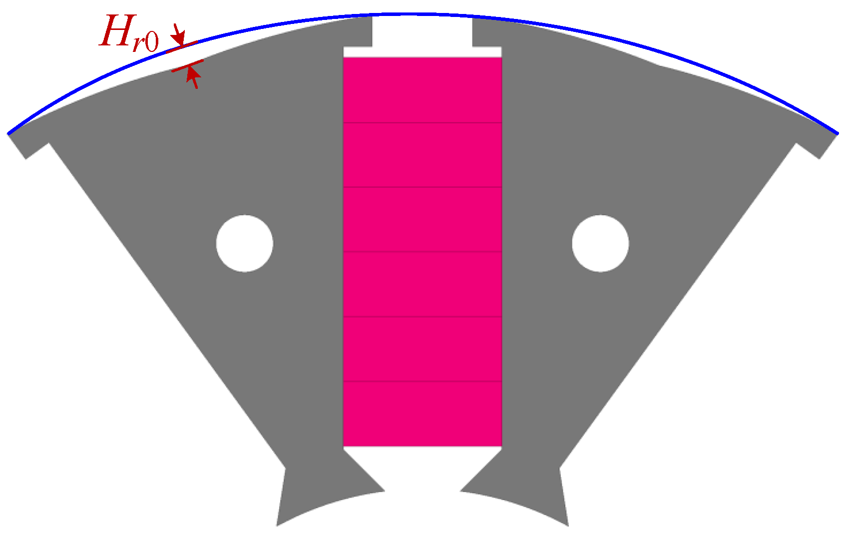
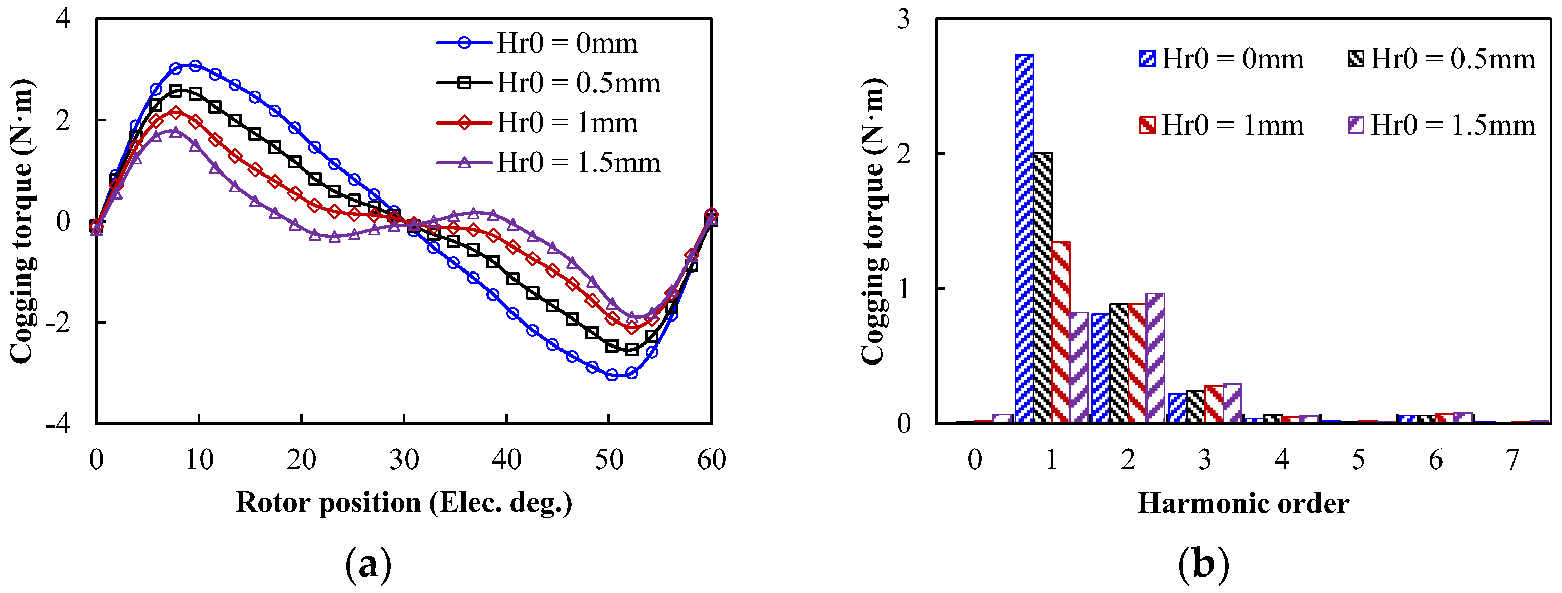
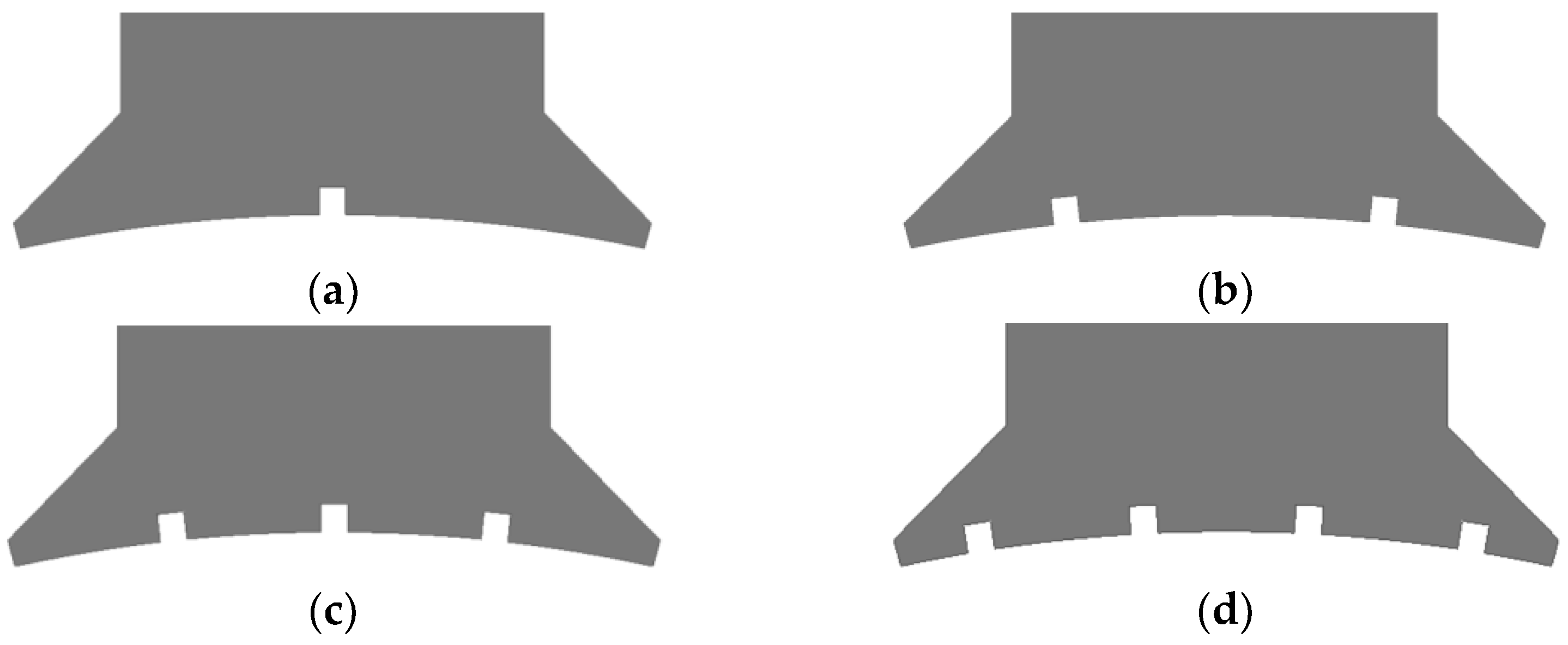
3.2. Uneven Rotor Core

In order to reduce the cogging torque, an uneven rotor core is employed in this paper, as shown in Figure 7. Then, the cogging torque wave versus different uneven rotor core distances under no-load is shown in Figure 8. The cogging torque gradually decreased with the increase of uneven rotor core distance, and the fundamental harmonic of the cogging torque was reduced as the distance increased. However, the 2nd harmonic of the cogging torque was increased. When Hr0 = 1.5 mm, the cogging torque decreased from 3.07 N·m to 1.77 N·m. In addition, the cogging torque wave versus different uneven rotor core distances under on-load is shown in Figure 9. It can be seen that the cogging torque decreased first and then increased with the increase of Hr0, with only small changes.

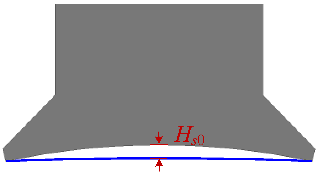
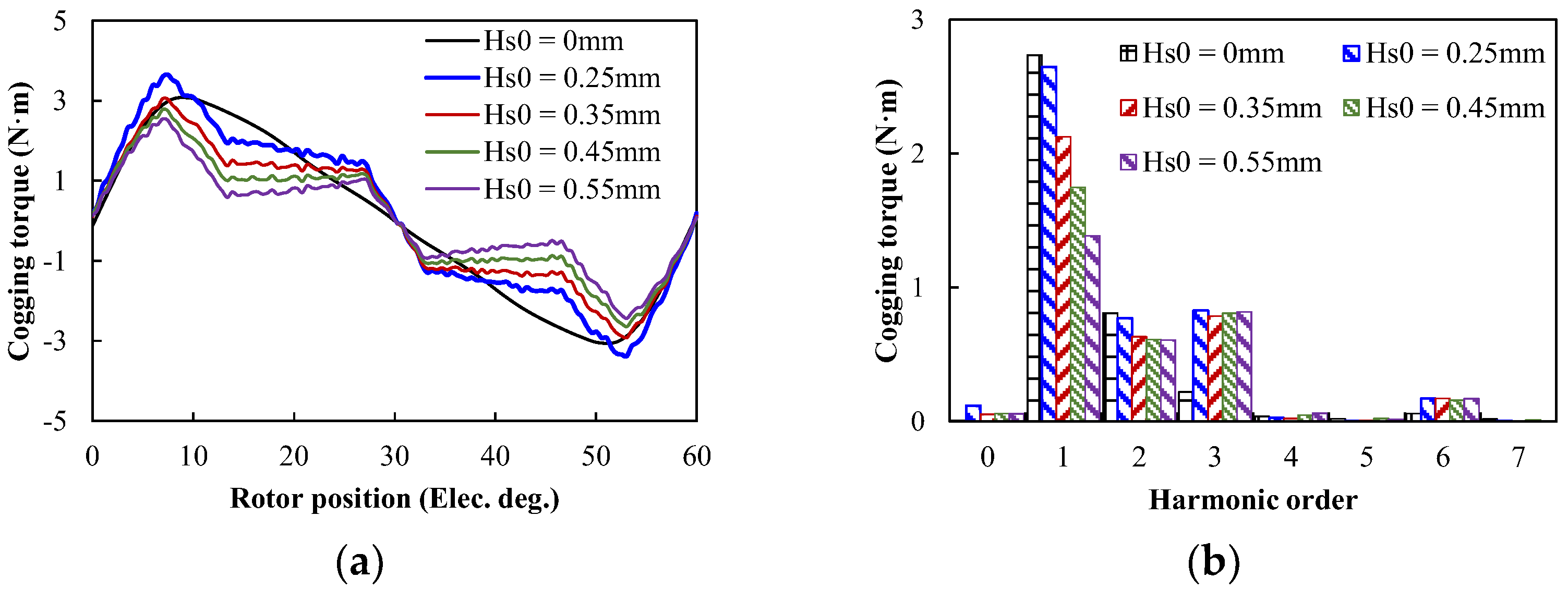
3.3. Uneven Stator Core

In this section, the influence of the uneven stator core on the cogging torque is explored, and the stator core is shown in Figure 10. The cogging torque waveforms of different uneven stator core distances under no-load are shown in Figure 11a, and the corresponding harmonic components are shown in Figure 11b. It can be seen that the cogging torque increased first and then decreased with the increase of different uneven stator core distances, and the fundamental harmonic of cogging torque was reduced as the distance increased. However, compared to Hs0 = 0 mm, the change of uneven stator core distances will be increased by 3rd harmonics. In addition, the cogging torque versus different uneven stator core distances at on-load is shown in Figure 12. The 1st harmonic increased with the increase of uneven stator core distances, and the 2nd harmonic decreased with the increase of uneven stator core distance. However, uneven stator core distance will bring additional harmonic content compared with the initial model. As a result, the structure of the uneven stator core will bring greater cogging torque under load conditions.

3.4. Stator Auxiliary Slotting

To evaluate the influence of stator auxiliary slotting on the cogging torque, the STPM machine stator tooth slotting is shown in Figure 13. The no-load cogging torque waveforms with different auxiliary slots are shown in Figure 14a. It can be seen that the auxiliary slot significantly decreased the cogging torque, and the four auxiliary slots had the least cogging torque. The harmonic analysis of the cogging torque waveforms was conducted, as shown in Figure 14b. The one, three, and four auxiliary slots can reduce the 1st harmonic. The two auxiliary slots increased the 1st harmonic, but the 2nd harmonic could be significantly reduced. Figure 15a shows the on-load cogging torque waveforms with different auxiliary slots. It can be seen that the two auxiliary slots could significantly decrease the on-load cogging torque, and the others increased the cogging torque. The harmonic analysis of the cogging torque waveforms is shown in Figure 15b. Compared with the no auxiliary slot, any auxiliary slot could suppress odd harmonics but increased the even harmonics of the cogging torque.

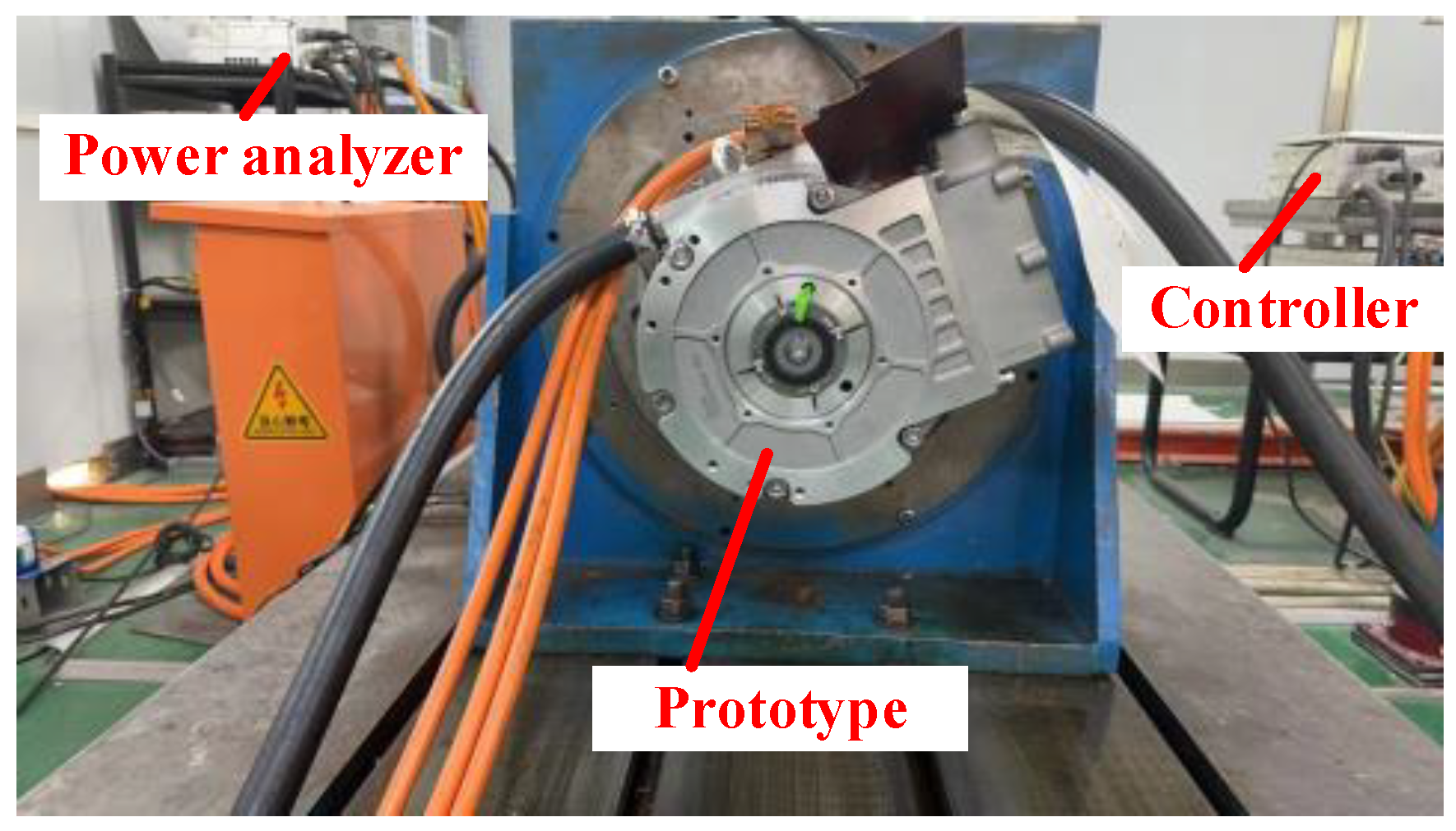
4. Experiment Validation

To validate the theoretical analyses, a 50 kW STPM machine with a rotor slot prototype was manufactured and tested on a testing rig; the test platform is shown in Figure 16. Then, the prototype is connected to a 100 kW PM machine through a torque transducer.

4.1. No-Load Performance

Figure 17 shows the comparison of no-load line voltage waveforms of FE results and the experimental results. It can be seen that the prototype had symmetric and sinusoidal no-load line back-EMF, and the root mean square (RMS) was achieved at 358.5 V. Compared with FE results, the tested no-load line back-EMF was slightly lower than the FE-predicted, and the total harmonic distortion (THD) of the FE-predicted and tested back-EMF were 3.5% and 3.2%, respectively. The error between FE-predicted results and tested results may have been caused by magnetic field saturation and manufacturing tolerance, which were within acceptable limits. The tested 3rd and 5th harmonic were 3.2 V and 0.9 V, respectively.

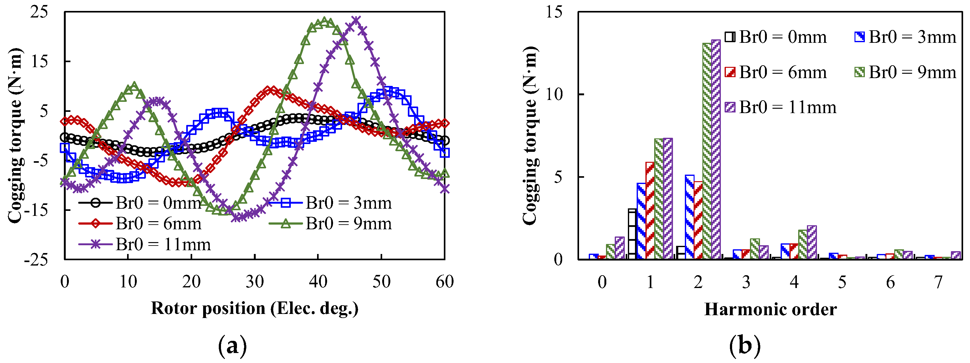
4.2. On-Load Performance

Figure 18a compares the output torque results by simulation and experiments with different currents at id = 0. Compared with 3D FE-predicted results, the 2D FE-predicted results were slightly high, which was mainly due to the neglected end flux leakage. In addition, it can be found that the experiment results were basically consistent with the FE-predicted results when the phase current was lower than the rated current. Meanwhile, when the phase current was larger than the rated current, the experiment results were less than FE-predicted, and the error of the experiment and FE-predicted results were slightly increased with the phase current. Overall, the FE-predicted results were in good agreement with the experiment results. In addition, the armature current waveform measured under rated conditions is shown in Figure 18b. It can be seen that the measured current waveform had a certain harmonic content due to the armature reaction, but the overall sine degree of the waveform was good, which had little influence on the output result.

5. Conclusions

In this article, a general analytical model of cogging torque accounting for rotor slots has been developed, which can provide a comprehensive investigation on the cogging torque of STPM machines. The characteristics of the cogging torque in the STPM machines, particularly the fundamental and harmonic content cogging torque are derived. The suppression techniques for minimizing the cogging torque are obtained, including the rotor slot width, stator auxiliary slot, and uneven rotor core. The cogging torque of the STPM machine with 12s10p is applied for analyses and the prototype is manufactured and tested to validate the FE-predicted results. The main finding of this paper can be summarized as follows:
(1)
The cogging torque of the STPM machine is not only affected by stator slots but also significantly influenced by rotor slots. It is possible to minimize the cogging torque in STPM machine by selecting the proper rotor slot opening width.
(2)
The work condition shows a great influence on harmonic amplitudes of cogging torques due to magnetic saturation, and the no-load cogging torque is mainly caused by fundamental, but the on-load cogging torque is mainly caused by the 2nd harmonic and 3rd harmonic.
(3)
The suitable rotor slot width can suppress the harmonic content of cogging torque under different conditions, and the stator auxiliary slot can reduce the fundamental content under different conditions.

Author Contributions

Paper writing, J.H.; simulation analysis, J.H.; prototype, C.W.; test, C.W. All authors have read and agreed to the published version of the manuscript.

Funding

This research was funded by Key Research and Development Project of Wuhu City under Award 2023yf014.

Data Availability Statement

The data are available from the corresponding author on reasonable request.

Conflicts of Interest

The authors declare no conflict of interest.

References

  1. Bilgin, B.; Liang, J.; Terzic, M.V.; Dong, J.; Rodriguez, R.; Trickett, E.; Emadi, A. Modeling and analysis of electric motors: State-of-the-art review. IEEE Trans. Transp. Electrif. 2019, 5, 602–617. [Google Scholar] [CrossRef]
  2. Gao, M.; Ren, J.; Hu, W.; Han, Y.; Geng, H.; Yan, S.; Xu, M. Armature Reaction Analysis and Performance Optimization of Hybrid Excitation Starter Generator for Electric Vehicle Range Extender. World Electr. Veh. J. 2023, 14, 286. [Google Scholar] [CrossRef]
  3. Yu, Y.; Pei, Y.; Chai, F.; Doppelbauer, M. Performance Comparison Between Permanent Magnet Synchronous Motor and Vernier Motor for In-Wheel Direct Drive. IEEE Trans. Ind. Electron. 2023, 70, 7761–7772. [Google Scholar] [CrossRef]
  4. Zhou, X.; Zhu, X.; Wu, W.; Xiang, Z.; Liu, Y.; Quan, L. Multi-objective Optimization Design of Variable-Saliency-Ratio PM Motor Considering Driving Cycles. IEEE Trans. Ind. Electron. 2021, 68, 6516–6526. [Google Scholar] [CrossRef]
  5. Wu, Z.Z.; Zhu, Z.Q.; Zhan, H.L. Comparative Analysis of Partitioned Stator Flux Reversal PM Machines Having Fractional-Slot Nonoverlapping and Integer-Slot Overlapping Windings. IEEE Trans. Energy Convers. 2016, 31, 776–788. [Google Scholar] [CrossRef]
  6. Zhao, W.; Chen, D.; Lipo, T.A.; Kwon, B.I. Dual Airgap Stator and Rotor-Permanent Magnet Machines with Spoke-type Configurations Using Phase-group Concentrated Coil Windings. IEEE Trans. Ind. Appl. 2017, 53, 3327–3335. [Google Scholar] [CrossRef]
  7. Kimiabeigi, M.; Long, R.; Widmer, J.D.; Gao, Y. Comparative Assessment of Single Piece and Fir-Tree-Based Spoke Type Rotor Designs for Low-cost Electric Vehicle Application. IEEE Trans. Energy Convers. 2017, 32, 486–494. [Google Scholar] [CrossRef]
  8. Fatemi, A.; Ionel, D.M.; Popescu, M.; Chong, Y.C.; Demerdash, N.A. Design Optimization of a High Torque Density Spoke-Type PM Motor for a Formula E Race Drive Cycle. IEEE Trans. Ind. Appl. 2018, 54, 4343–4354. [Google Scholar] [CrossRef]
  9. Galioto, S.J.; Reddy, P.B.; El-Refaie, A.M.; Alexander, J.P. Effect of magnet types on performance of high speed spoke interior permanent magnet machines designed for traction applications. IEEE Trans. Ind. Appl. 2014, 51, 2148–2160. [Google Scholar] [CrossRef]
  10. Muthusamy, M.; Hendershot, J.; Pillay, P. Design of a Spoke Type PMSM With SMC Stator Core for Traction Applications. IEEE Trans. Ind. Appl. 2023, 59, 1418–1436. [Google Scholar] [CrossRef]
  11. Liu, G.; Wang, Y.; Chen, Q.; Xu, G.; Song, C. Multiobjective Deterministic and Robust Optimization Design of a New Spoke-Type Permanent Magnet Machine for the Improvement of Torque Performance. IEEE Trans. Ind. Electron. 2020, 67, 10202–10212. [Google Scholar] [CrossRef]
  12. Huynh, T.A.; Che, V.H.; Hsieh, M.F. Maximization of High-Efficiency Operating Range of Spoke-Type PM E-Bike Motor by Optimization Through New Motor Constant. IEEE Trans. Ind. Appl. 2023, 59, 1328–1339. [Google Scholar] [CrossRef]
  13. Luu, T.P.; Choi, S.K.; Park, S.Y.; Lee, J.Y. Effect of Manufacturing Tolerances on Cogging Torque of Spoke-type Permanent Magnet Synchronous Motor. In Proceedings of the 2021 24th International Conference on Electrical Machines and Systems (ICEMS), Gyeongju, Korea, 19–21 November 2021; pp. 1054–1059. [Google Scholar]
  14. Zhao, W.; Lipo, T.A.; Kwon, B.I. Torque Pulsation Minimization in Spoke-type Interior Permanent Magnet Motors With Skewing and Sinusoidal Permanent Magnet Configurations. IEEE Trans. Magn. 2015, 51, 8110804. [Google Scholar] [CrossRef]
  15. Zhao, W.; Kwon, J.W.; Wang, X.; Lipo, T.A.; Kwon, B.I. Optimal Design of a Spoke-type Permanent Magnet Motor with Phase-group Concentrated-coil Windings to Minimize Torque Pulsations. IEEE Trans. Magn. 2017, 53, 8104604. [Google Scholar] [CrossRef]
  16. Xiao, Y.; Zhu, Z.Q.; Jewell, G.W.; Chen, J.T.; Wu, D.; Gong, L.M. A Novel Asymmetric Interior Permanent Magnet Synchronous Machine. IEEE Trans. Ind. Appl. 2022, 58, 3370–3382. [Google Scholar] [CrossRef]
  17. Tang, X.; Wang, X.; Sun, S.; Zhao, J. Analytical Analysis and Study of Reduction Methods of Cogging Torque in Line-start Permanent Magnet Synchronous Motors. Proc. CSEE 2016, 36, 1395–1403. [Google Scholar]
  18. Zhu, Z.Q.; Howe, D. Instantaneous Magnetic Field Distribution in Brushless Permanent Magnet DC Motors. III. Effect of Stator Slotting. IEEE Trans. Magn. 1993, 29, 143–151. [Google Scholar] [CrossRef]
Figure 1. Topology of the STPM machine.
Wevj 15 00376 g001
Figure 2. Cogging torques at no−load with different methods.
Wevj 15 00376 g002
Figure 3. Cogging torque under no−load. (a) Waveform. (b) Harmonic spectrum.
Wevj 15 00376 g003
Figure 4. Cogging torque with on−load. (a) Waveforms. (b) Harmonic.
Wevj 15 00376 g004
Figure 5. Cogging torque versus different rotor slots under no load. (a) Waveform. (b) Harmonic.
Wevj 15 00376 g005
Figure 6. Cogging torque versus different rotor slots under on-load. (a) Waveforms. (b) Harmonic.
Wevj 15 00376 g006
Figure 7. Uneven rotor core structure.
Wevj 15 00376 g007
Figure 8. Cogging torque versus different uneven rotor core distance under no-load. (a) Waveforms. (b) Harmonic.
Wevj 15 00376 g008
Figure 9. Cogging torque versus different uneven rotor core distance under on-load. (a) Waveforms. (b) Harmonic.
Wevj 15 00376 g009
Figure 10. Uneven stator core structure.
Wevj 15 00376 g010
Figure 11. Cogging torque versus different uneven stator core distance under no-load. (a) Waveforms. (b) Harmonic.
Wevj 15 00376 g011
Figure 12. Cogging torque versus different uneven stator core distance under on-load. (a) Waveforms. (b) Harmonic.
Wevj 15 00376 g012
Figure 13. Stator auxiliary slot designs. (a) One auxiliary slot. (b) Two auxiliary slots. (c) Three auxiliary slots. (d) Four auxiliary slots.
Wevj 15 00376 g013
Figure 14. Cogging torque with different auxiliary slots under no−load. (a) Waveform. (b) Harmonics.
Wevj 15 00376 g014
Figure 15. Cogging torques of STPM machine with different auxiliary slots under on−load. (a) Waveform. (b) Harmonics.
Wevj 15 00376 g015
Figure 16. STPM machine with a rotor slot prototype test platform.
Wevj 15 00376 g016
Figure 17. Line back-EMF under 4800 r/min. (a) Waveform. (b) Harmonic spectra.
Wevj 15 00376 g017
Figure 18. Torque versus phase current. (a) Waveforms. (b) Phase current waveform.
Wevj 15 00376 g018
Table 1. Main design parameters of the STPM machine.
ParametersValueParametersValue
Rated power (kW)40Peak power (kW)80
Rated torque (N·m)160Peak torque (N·m)300
PM thickness (mm)11PM width (mm)17
Outer diameter (mm)180Inner diameter (mm)120
Stack length (mm)180Air-gap length (mm)1
Turns per coil6Stator slots12
Pole pair5Number of phases3
Disclaimer/Publisher’s Note: The statements, opinions and data contained in all publications are solely those of the individual author(s) and contributor(s) and not of MDPI and/or the editor(s). MDPI and/or the editor(s) disclaim responsibility for any injury to people or property resulting from any ideas, methods, instructions or products referred to in the content.

