
CFD-Guided Evaluation of Spark-Assisted Gasoline Compression Ignition for Cold Idle Operation

Abstract
:1. Introduction
2. Methodology
2.1. Experimental Setup
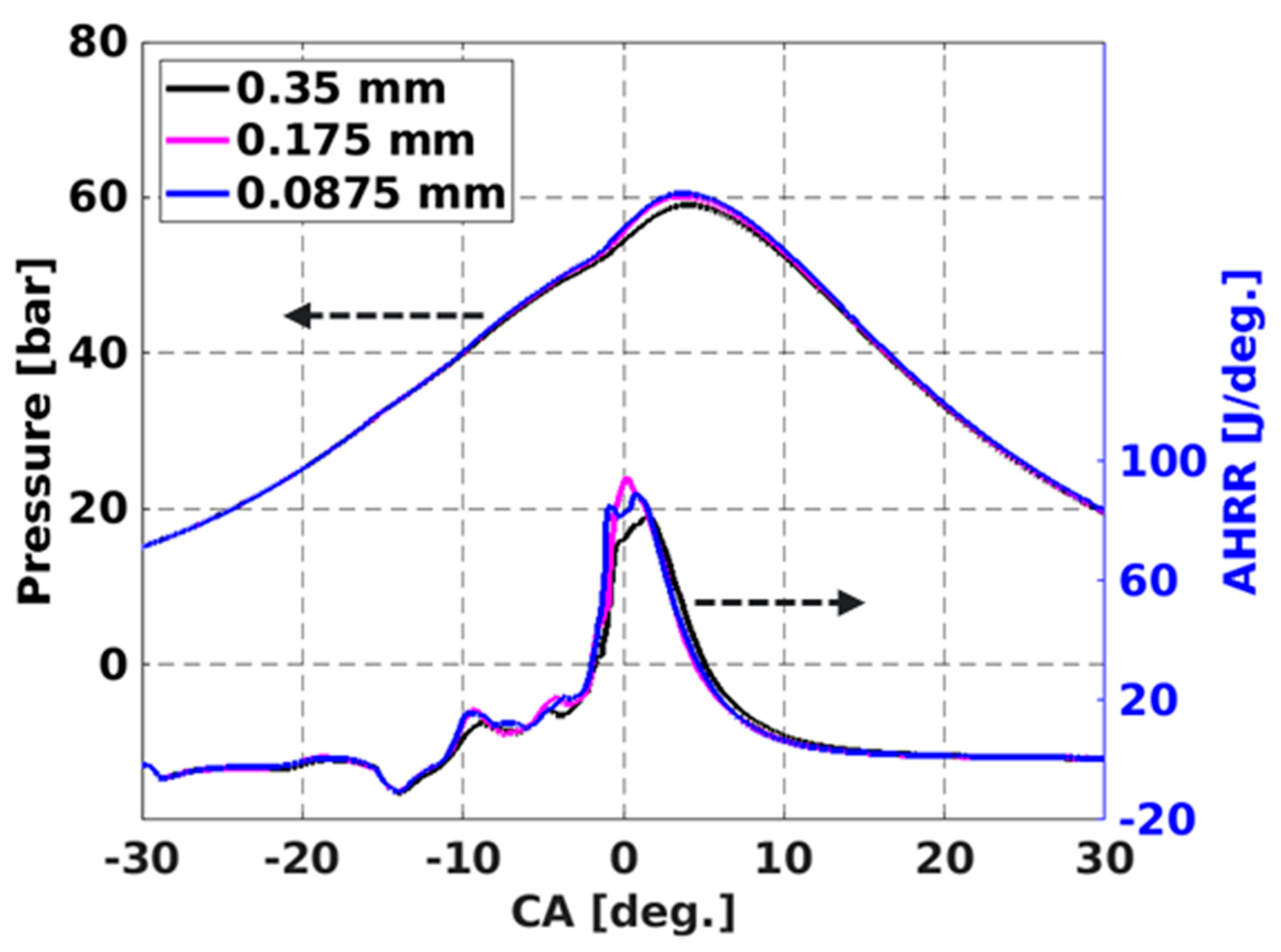
2.2. CFD Model Description
3. Results and Discussions
3.1. Design Variables
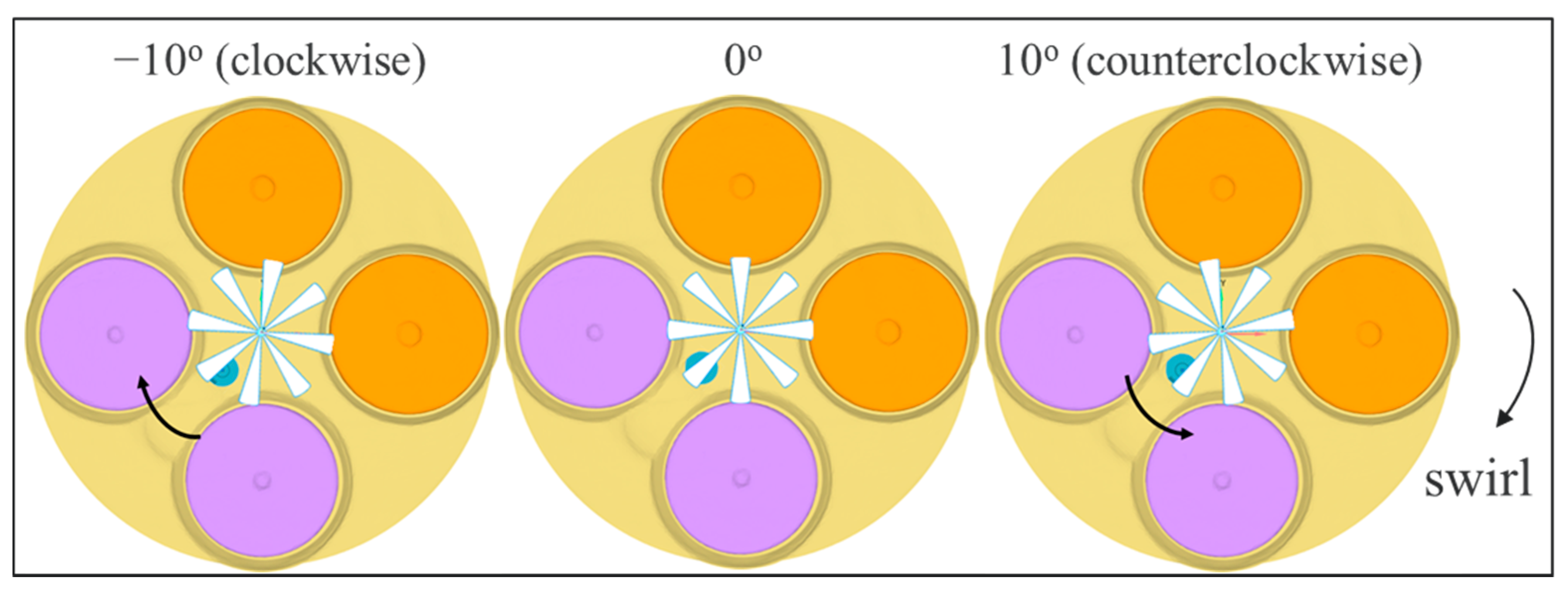
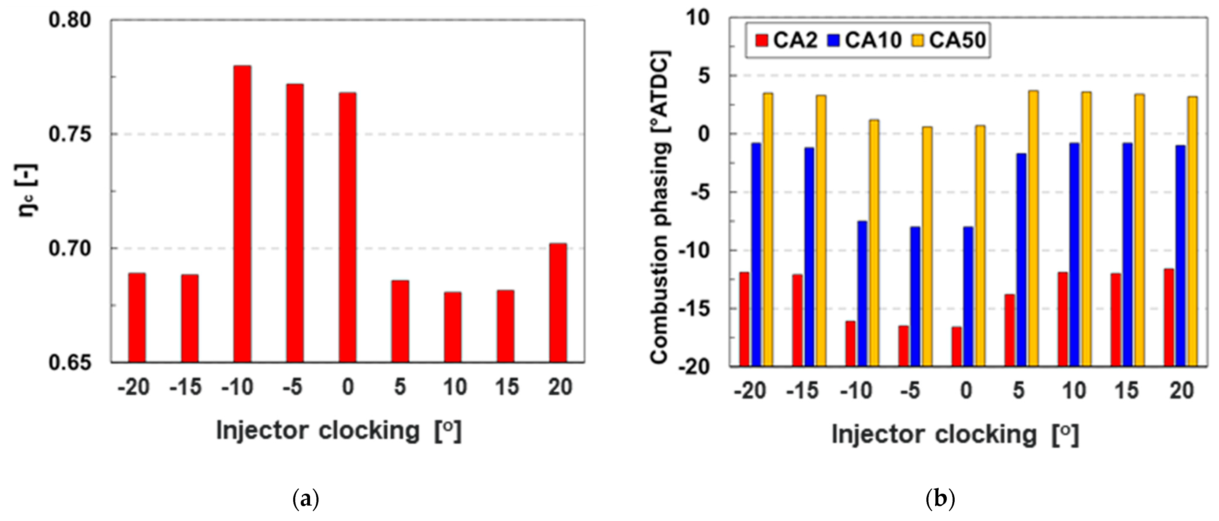
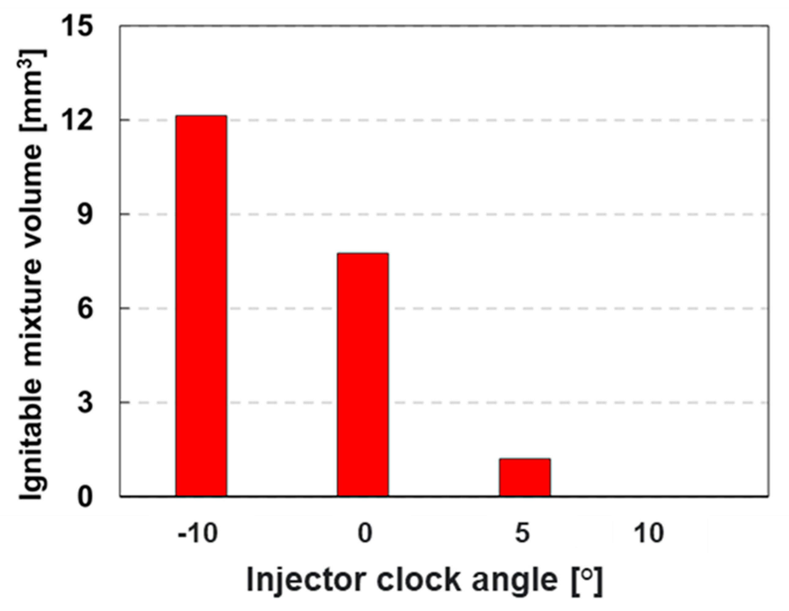
3.2. Effect of Injector Clocking
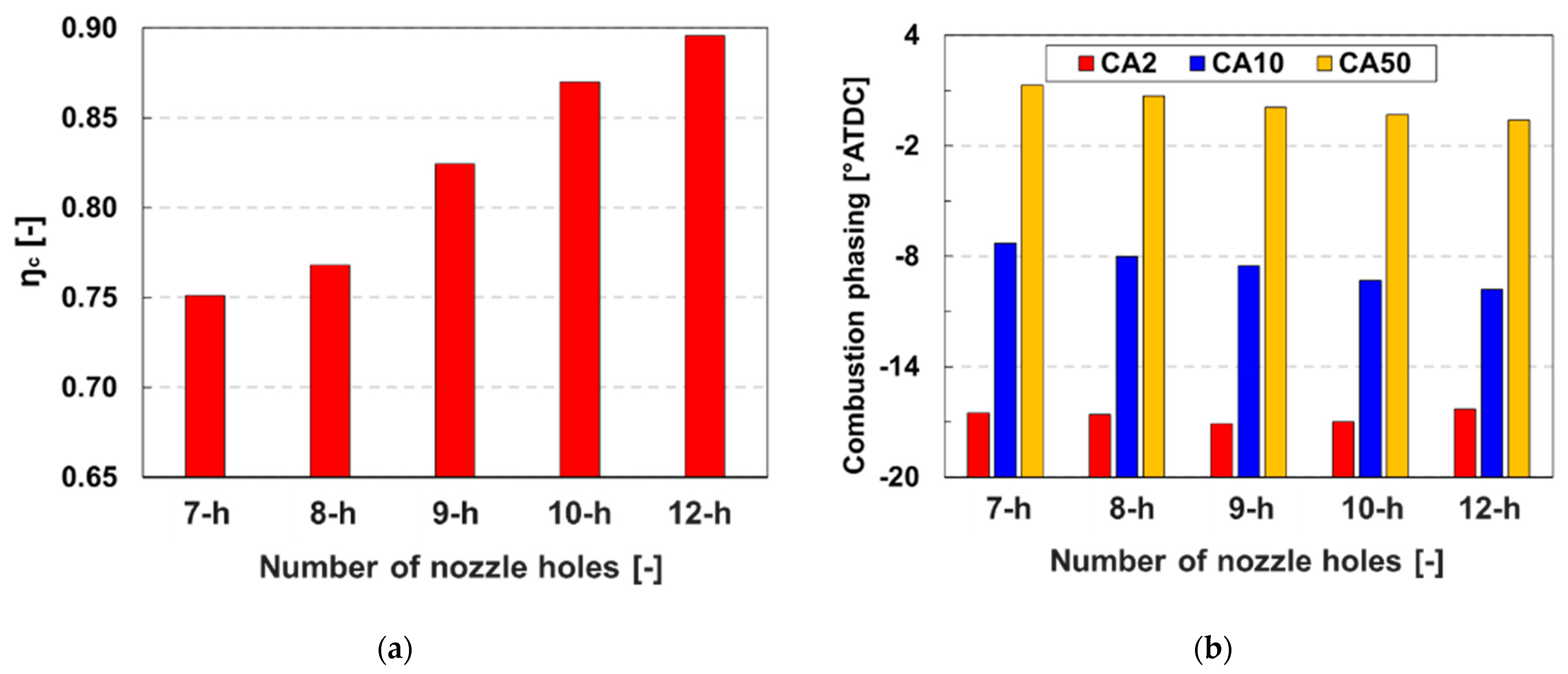
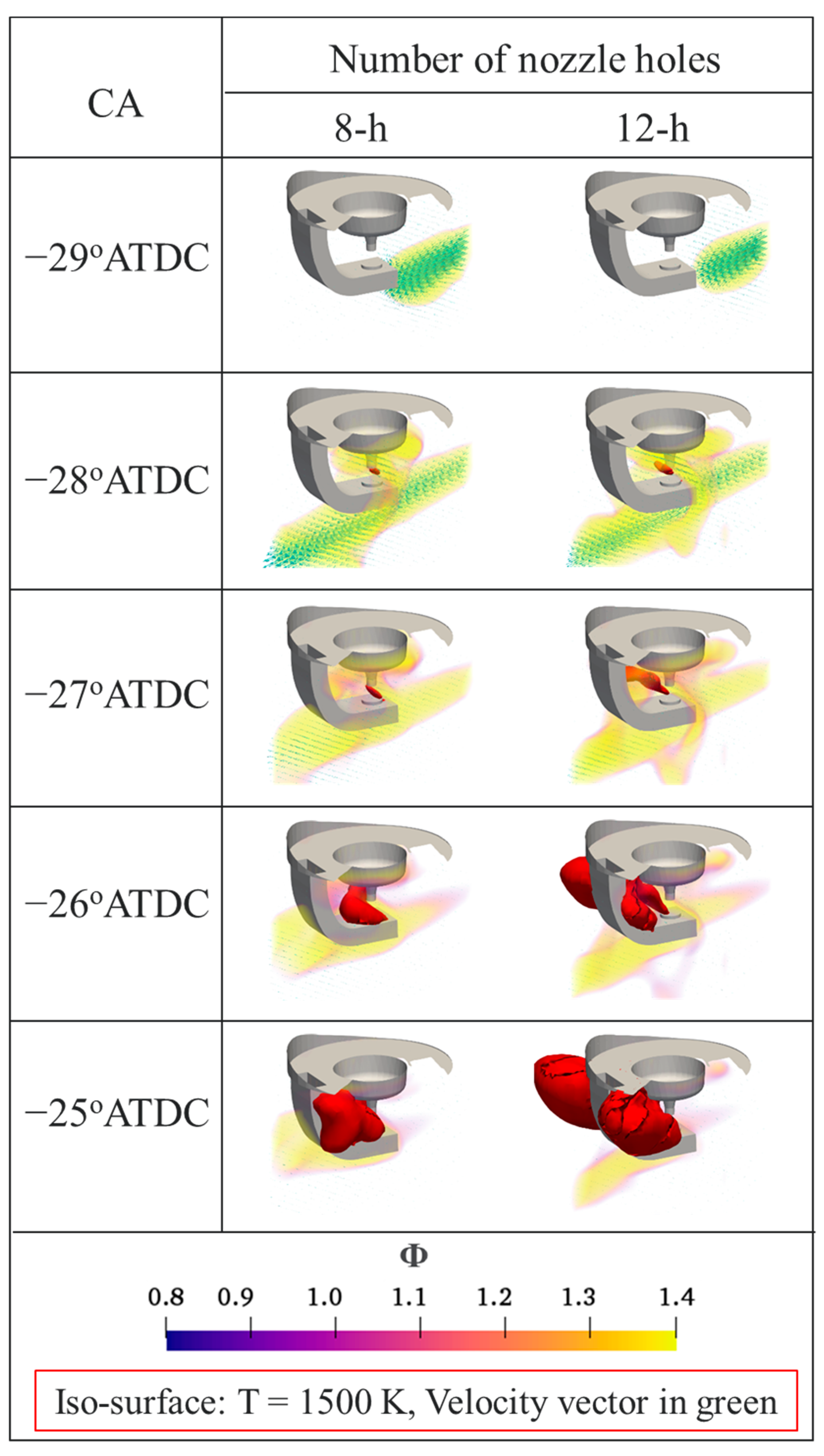
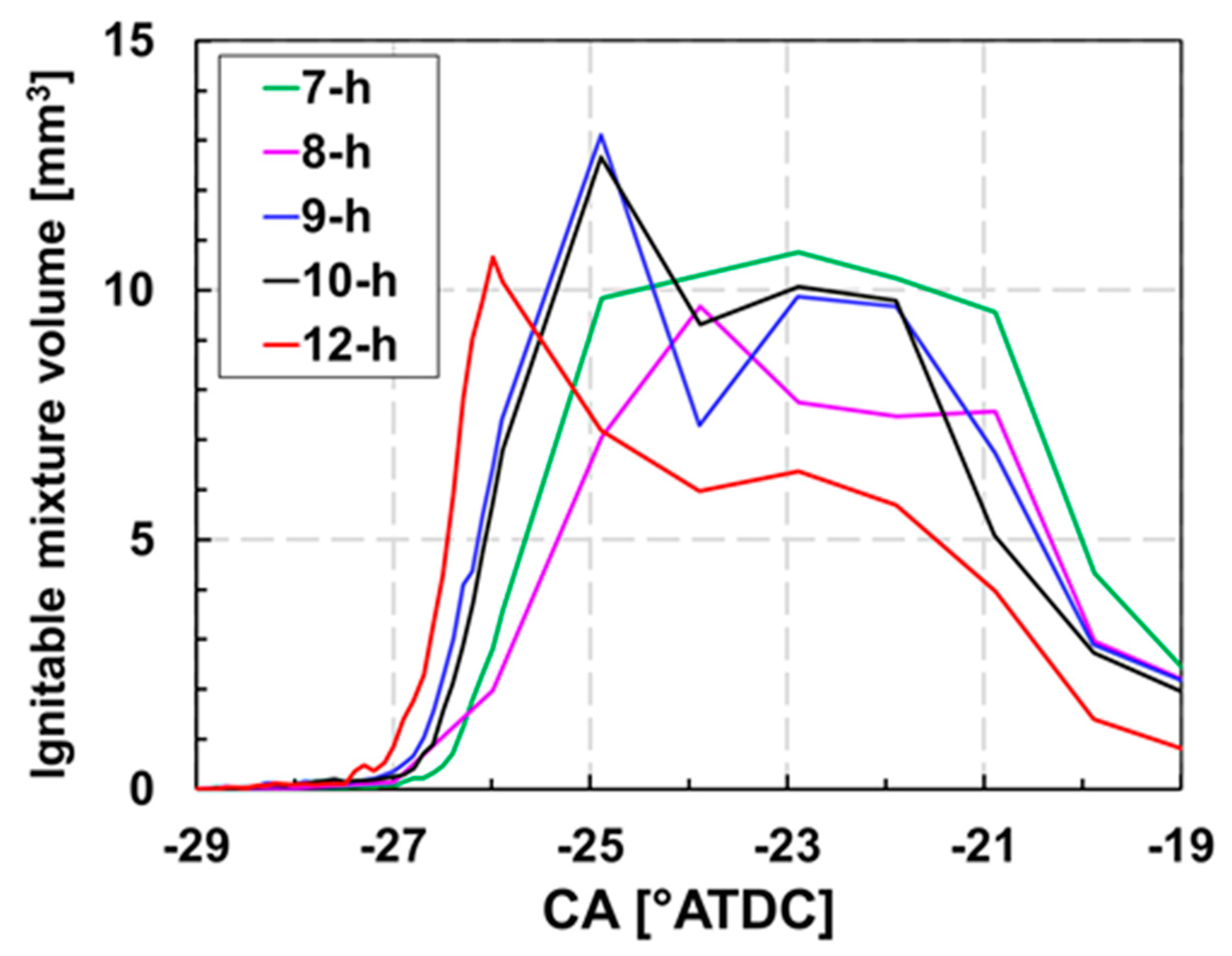
3.3. Effect of Number of Nozzle Holes
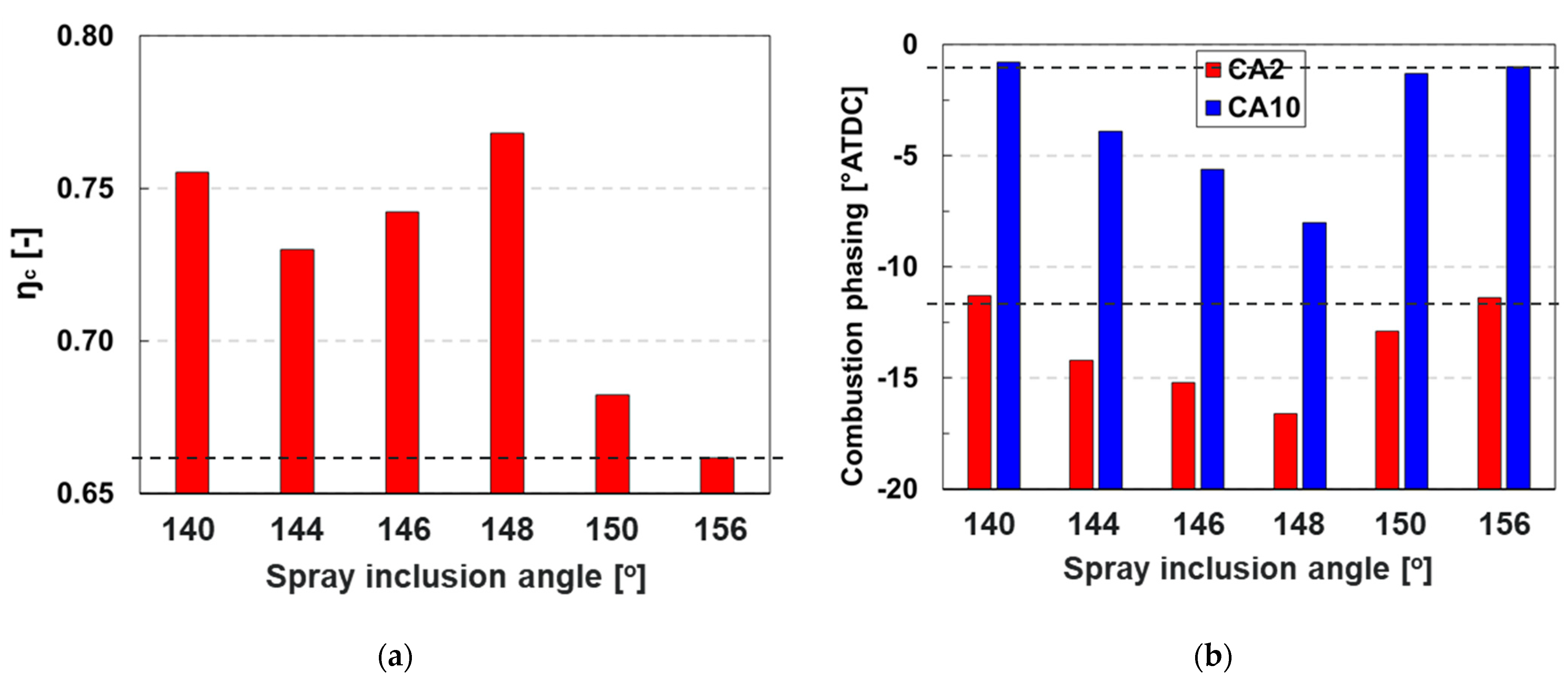
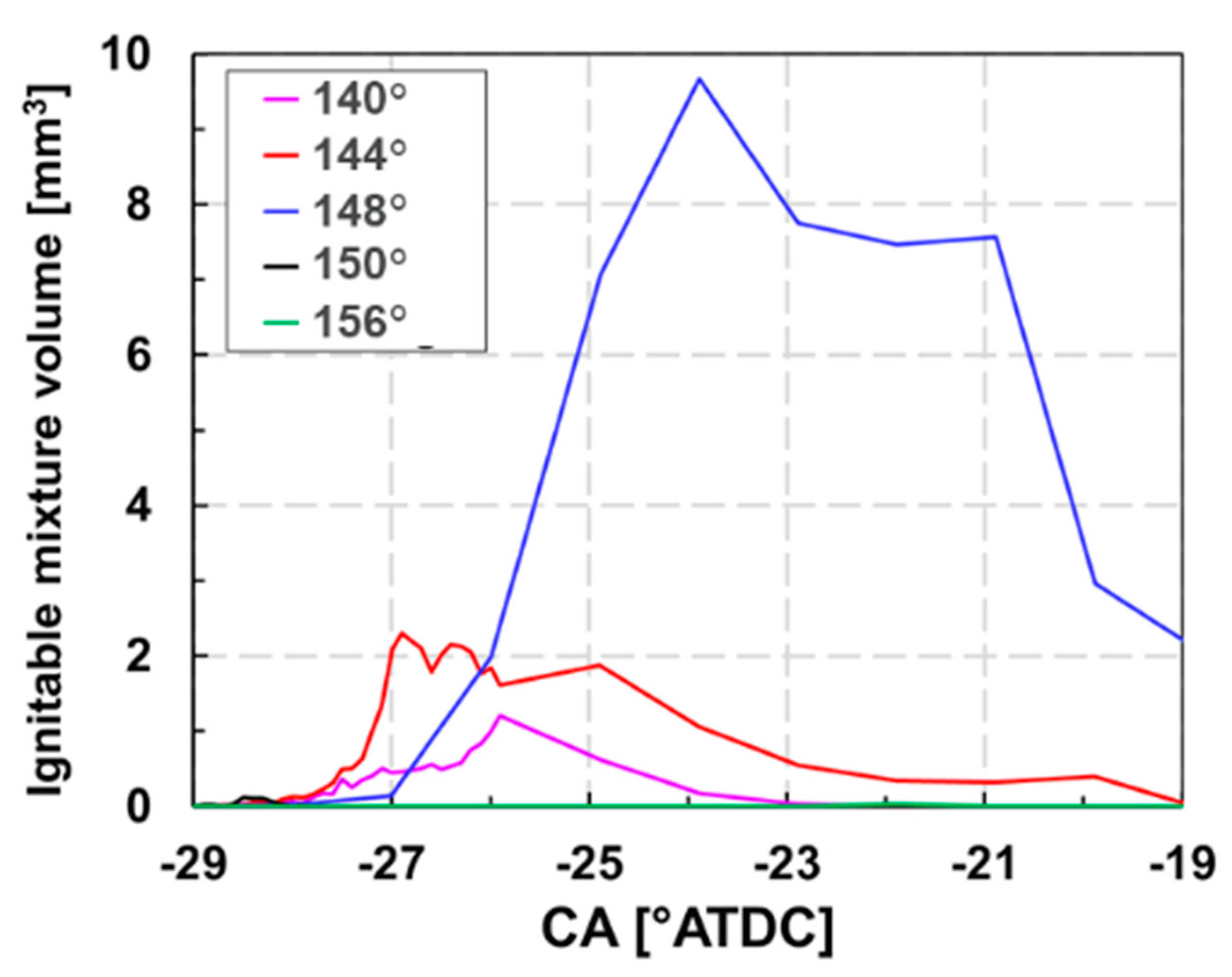
3.4. Effect of Spray Inclusion Angle
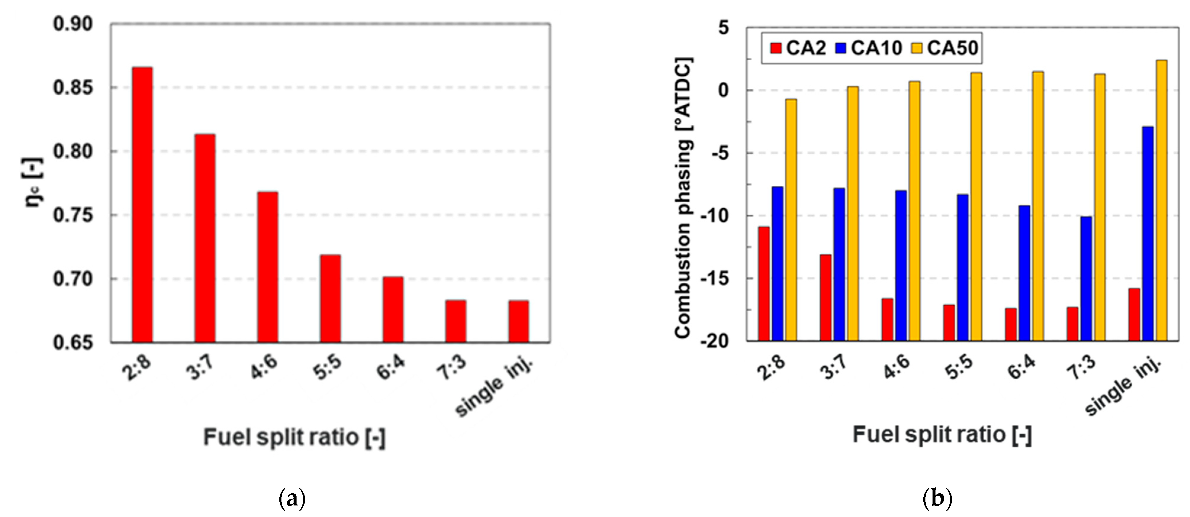
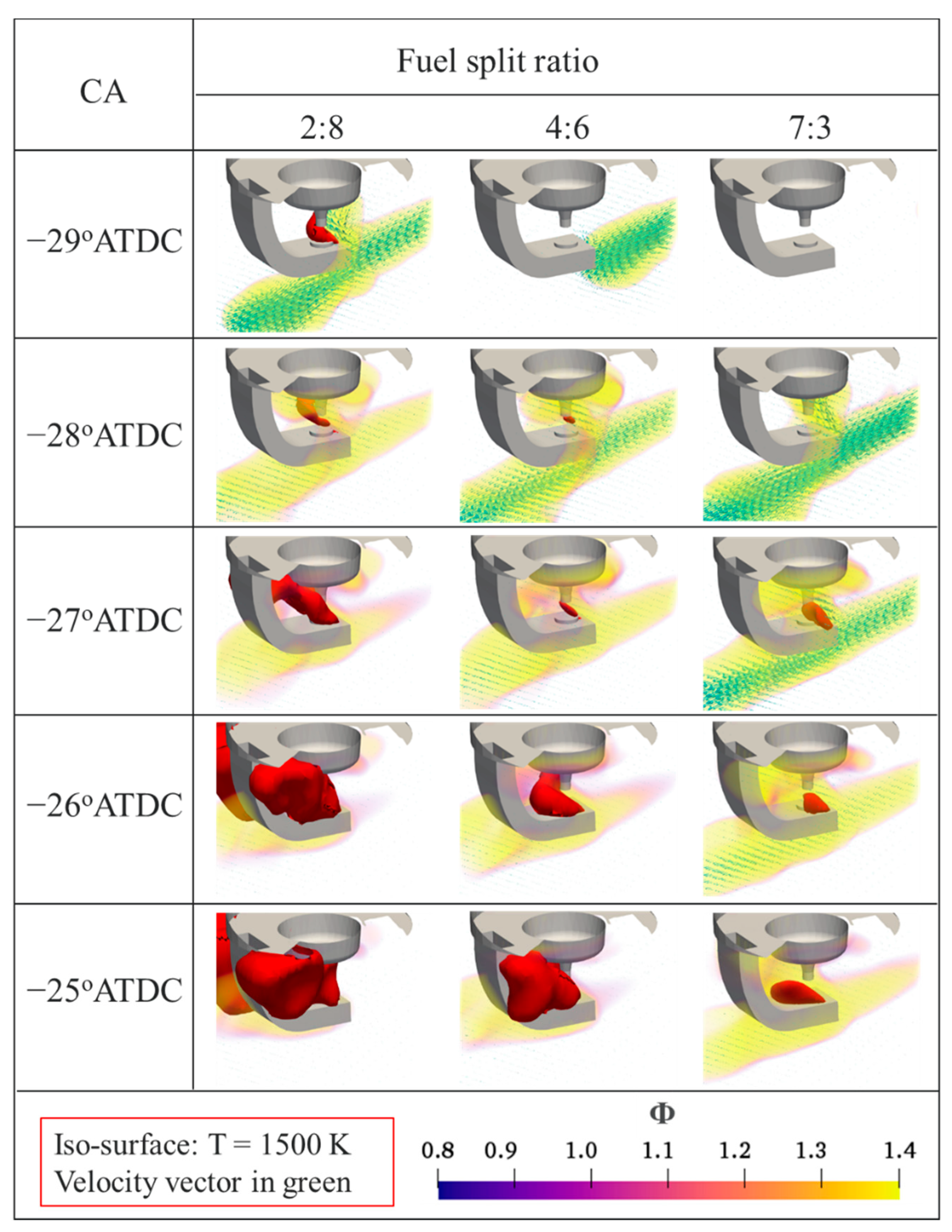
3.5. Effect of Fuel Split Ratio
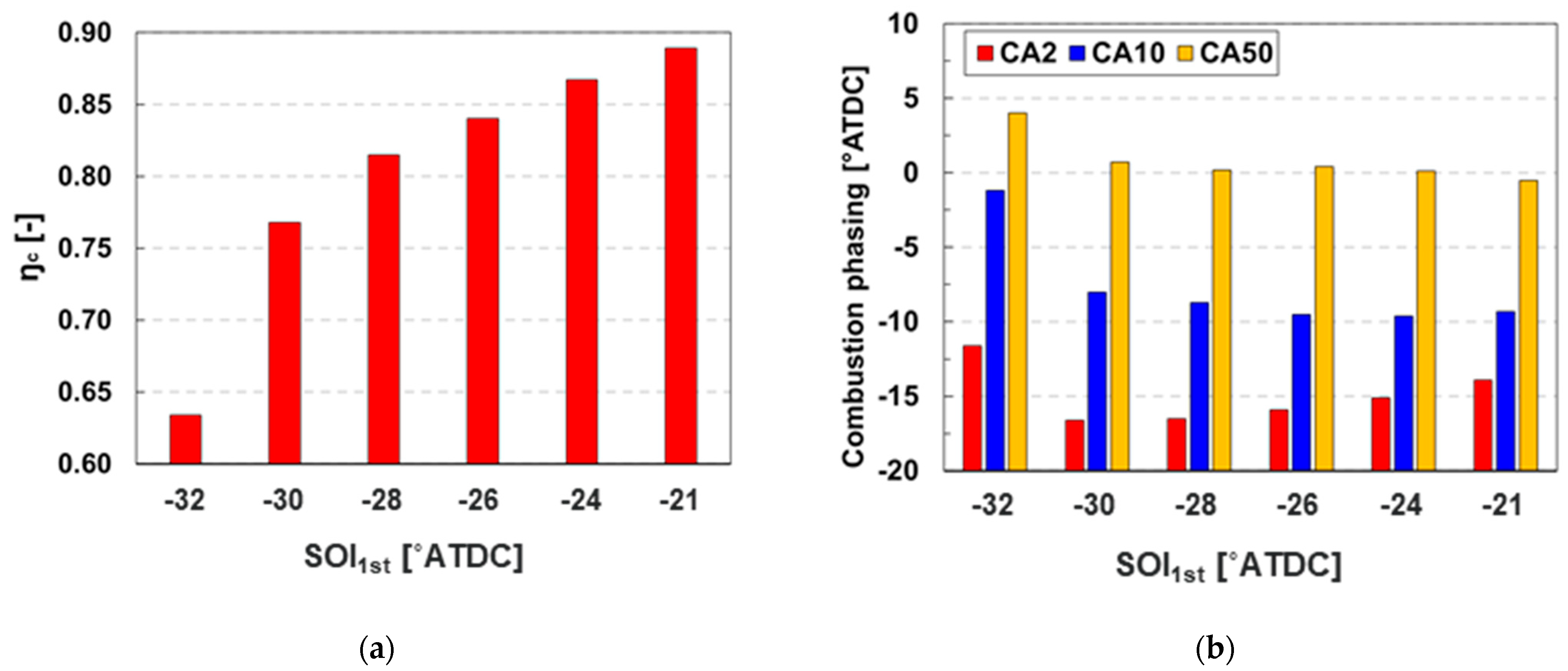
3.6. Effect of Fuel Injection Strategy
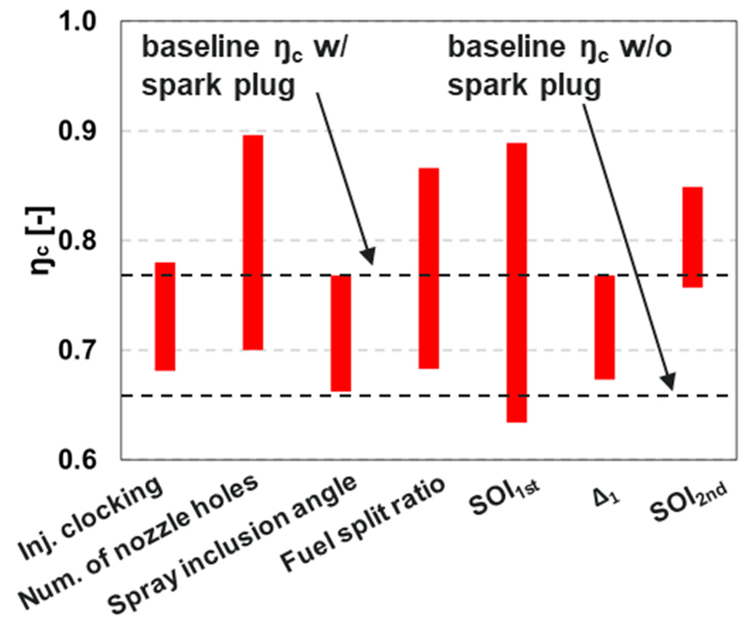
3.7. Overview of the Spray Pattern and Fuel Injection Strategy Effects on Spark Assistance
4. Conclusions
- An injector clocking angle between −10 and 0° produced the best synergy between the spray plume–spark plug interaction and swirl motion on influencing the flame kernel development and local flow field, resulting in enhanced combustion efficiency.
- Increasing the number of nozzle holes was effective in promoting combustion. Combustion efficiency increased and CA50 advanced. Twelve holes provided the best performance.
- The spray inclusion angle affected the interaction between the spark plug and spray plumes and further influenced the combustion process. A spray inclusion angle of 148° was found to be most favorable.
- The fuel split ratio affected the fuel–air mixing process and flame kernel growth. Split injections performed better than a single injection. A split ratio of 2:8 had the highest combustion efficiency.
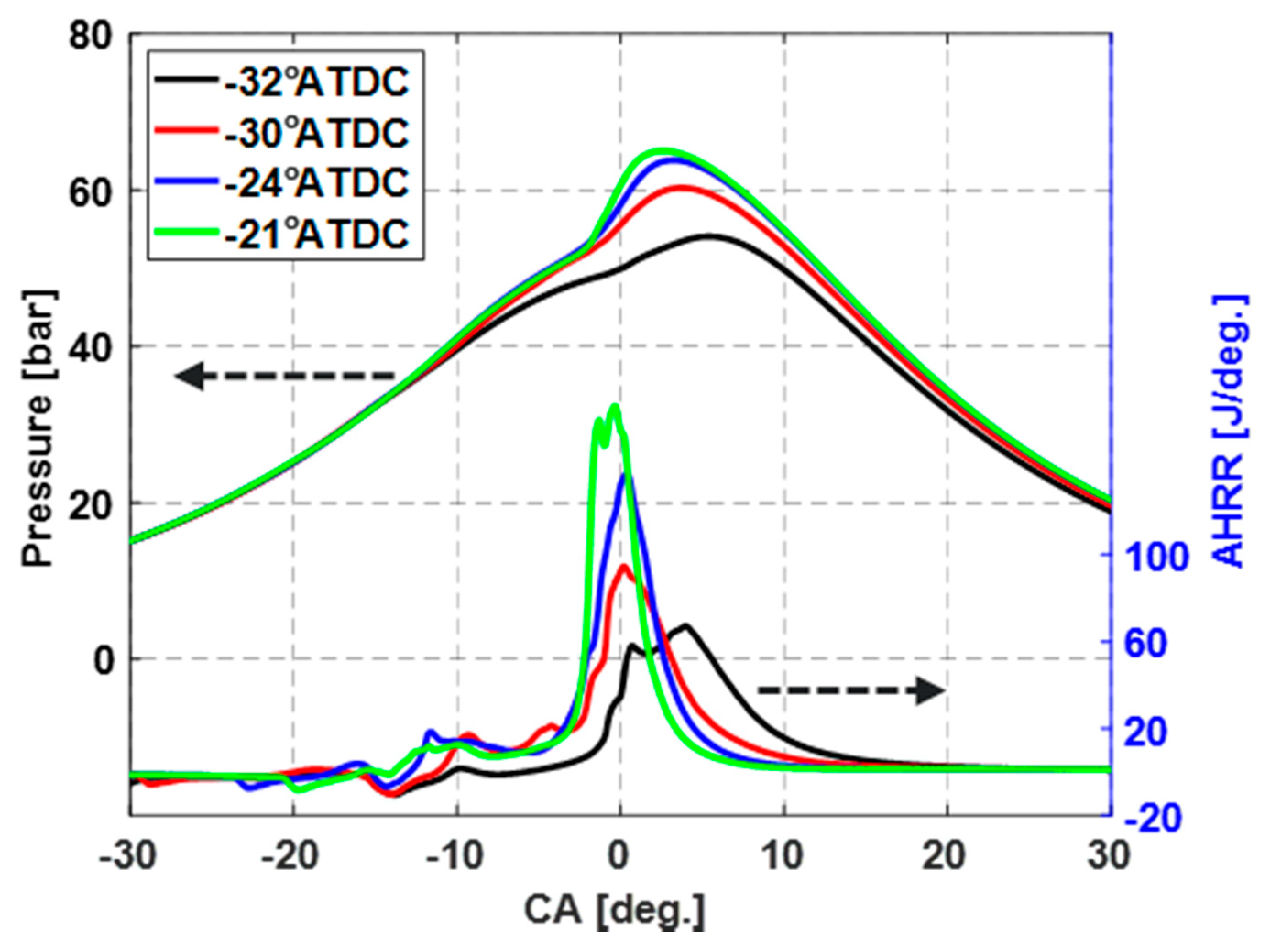
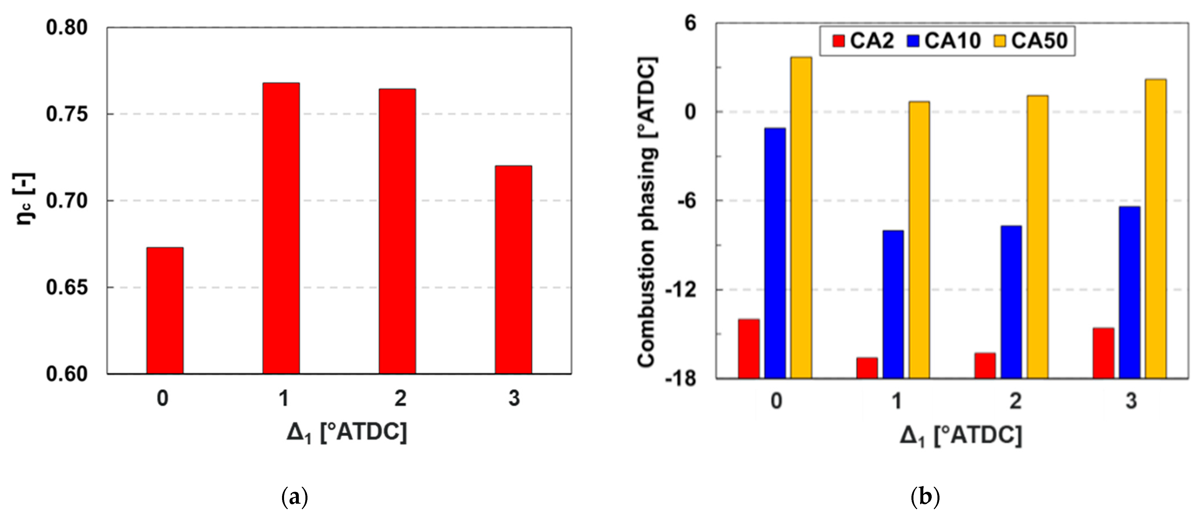
- Combustion efficiency was notably sensitive to the SOI1st. The difference between the spark timing and SOI1st (i.e., Δ1) of 1 showed the best combustion performance.
- The number of nozzle holes and fuel injection timing (SOI1st) had the most significant effects on the engine combustion performance.
Author Contributions
Funding
Institutional Review Board Statement
Informed Consent Statement
Data Availability Statement
Conflicts of Interest
Nomenclature
| ŋc | Combustion efficiency |
| Φ | Equivalence ratio |
| φ | Spray inclusion angle |
| SOI1st | The first start of injection |
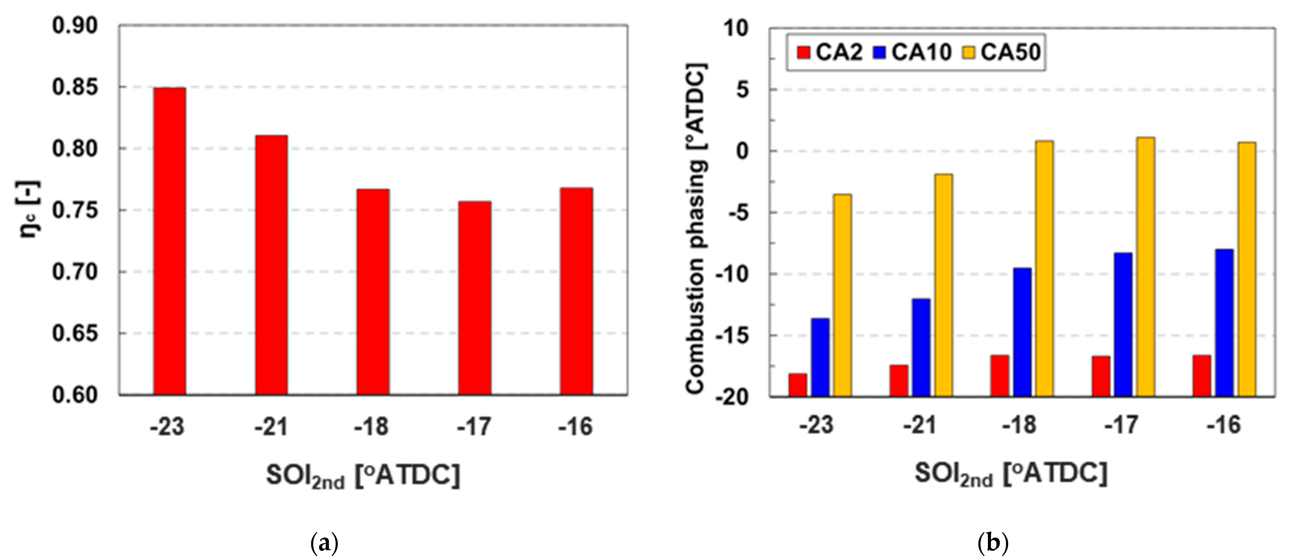
| SOI2nd | The second start of injection |
| φ | Spray inclusion angle |
| Δ1 | Difference between spark timing and SOI1st |
References
- Andrae, J.; Brinck, T.; Kalghatgi, G. HCCI experiments with toluene reference fuels modeled by a semidetailed chemical kinetic model. Combust. Flame 2008, 155, 696–712. [Google Scholar] [CrossRef]
- An, Y.; Jaasim, M.; Raman, V.; Pérez, F.E.H.; Sim, J.; Chang, J.; Im, H.G.; Johansson, B. Homogeneous charge compression ignition (HCCI) and partially premixed combustion (PPC) in compression ignition engine with low octane gasoline. Energy 2018, 158, 181–191. [Google Scholar] [CrossRef]
- Epping, K.; Aceves, S.; Bechtold, R.; Dec, J.E. The Potential of HCCI Combustion for High Efficiency and Low Emissions; SAE Technical Paper 2002-01-1923; SAE International: San Diego, CA, USA, 2002. [Google Scholar] [CrossRef]
- Noehre, C.; Andersson, M.; Johansson, B.; Hultqvist, A. Characterization of Partially Premixed Combustion. In Proceedings of the Powertrain & Fluid Systems Conference and Exhibition, Toronto, OB, Canada, 16–19 October 2006. [Google Scholar] [CrossRef]
- Cho, K.; Han, M.; Wagner, R.; Sluder, C.S. Mixed-Source EGR for Enabling High Efficiency Clean Combustion Modes in a Light-Duty Diesel Engine. SAE Int. J. Engines 2008, 1, 457–465. [Google Scholar] [CrossRef]
- Kokjohn, S.L.; Hanson, R.; Splitter, D.; Kaddatz, J.; Reitz, R.D. Fuel Reactivity Controlled Compression Ignition (RCCI) Combustion in Light- and Heavy-Duty Engines. SAE Int. J. Engines 2011, 4, 360–374. [Google Scholar] [CrossRef]
- Prikhodko, V.Y.; Curran, S.J.; Barone, T.L.; Lewis, S.A.; Storey, J.M.; Cho, K.; Wagner, R.M.; Parks, J.E. Emission Characteristics of a Diesel Engine Operating with In-Cylinder Gasoline and Diesel Fuel Blending. SAE Int. J. Fuels Lubr. 2010, 3, 946–955. [Google Scholar] [CrossRef]
- Roberts, J.; Kokjohn, S.; Hou, D.; Huang, Y. Performance of Gasoline Compression Ignition (GCI) with On-Demand Reactivity Enhancement over Simulated Drive Cycles; SAE Technical Paper 2018-01-0255; SAE International: Detroit, MI, USA, 2018. [Google Scholar] [CrossRef]
- Reitz, R.D.; Duraisamy, G. Review of high efficiency and clean reactivity controlled compression ignition (RCCI) combustion in internal combustion engines. Prog. Energy Combust. Sci. 2015, 46, 12–71. [Google Scholar] [CrossRef] [Green Version]
- Kalghatgi, G.T.; Risberg, P.; Angstrom, H.-E. Partially Pre-Mixed Auto-Ignition of Gasoline to Attain Low Smoke and Low NOx at High Load in a Compression Ignition Engine and Comparison with a Diesel Fuel; SAE Technical Paper 2007-01-0006; SAE International: Cape Town, South Africa, 2007. [Google Scholar] [CrossRef]
- Weall, A.; Collings, N. Investigation into Partially Premixed Combustion in a Light-Duty Multi-Cylinder Diesel Engine Fuelled with a Mixture of Gasoline and Diesel; SAE Technical Paper 2007-01-4058; SAE International: Rosemont, IL, USA, 2007. [Google Scholar] [CrossRef]
- Sellnau, M.; Sinnamon, J.; Hoyer, K.; Husted, H. Gasoline Direct Injection Compression Ignition (GDCI)—Diesel-like Efficiency with Low CO2 Emissions. SAE Int. J. Engines 2011, 4, 2010–2022. [Google Scholar] [CrossRef]
- Cho, K.; Latimer, E.; Lorey, M.; Cleary, D.J.; Sellnau, M. Gasoline Fuels Assessment for Delphi’s Second Generation Gasoline Direct-Injection Compression Ignition (GDCI) Multi-Cylinder Engine. SAE Int. J. Engines 2017, 10, 1430–1442. [Google Scholar] [CrossRef]
- Dec, J.E.; Dernotte, J.; Ji, C. Increasing the Load Range, Load-to-Boost Ratio, and Efficiency of Low-Temperature Gasoline Combustion (LTGC) Engines. SAE Int. J. Engines 2017, 10, 1256–1274. [Google Scholar] [CrossRef]
- Cho, K.; Zhao, L.; Ameen, M.; Zhang, Y.; Pei, Y.; Moore, W.; Sellnau, M. Understanding Fuel Stratification Effects on Partially Premixed Compression Ignition (PPCI) Combustion and Emissions Behaviors. In Proceedings of the WCX SAE World Congress Experience, Detroit, MI, USA, 9–11 April 2019. [Google Scholar] [CrossRef]
- Rose, K.; Ariztegui, J.; Cracknell, R.; Dubois, T.; Hamje, H.; Pellegrini, L.; Rickeard, D.; Heuser, B.; Schnorbus, T.; Kolbeck, A. Exploring a Gasoline Compression Ignition (GCI) Engine Concept; SAE Technical Paper 2013-01-0911; SAE International: Detroit, MI, USA, 2013. [Google Scholar] [CrossRef] [Green Version]
- Zhao, L.; Ameen, M.; Pei, Y.; Zhang, Y.; Kumar, P.; Tzanetakis, T.; Traver, M. Numerical Evaluation of Gasoline Compression Ignition at Cold Conditions in a Heavy-Duty Diesel Engine; SAE Technical Paper 2020-01-0778; SAE International: Detroit, MI, USA, 2020. [Google Scholar] [CrossRef]
- Zhao, L.; Ameen, M.M.; Pei, Y.; Zhang, Y.; Traver, M.; Garcia-Oliver, J.; Vera-Tudela, W. Effect of Fuel Properties on Spray and Combustion Characteristics under Compression Ignition Engine Conditions. In Proceedings of the 11th US National Combustion Meeting, Pasadena, CA, USA, 24–27 March 2019. [Google Scholar]
- Zhang, Y.; Kumar, P.; Pei, Y.; Traver, M.; Cleary, D. An Experimental and Computational Investigation of Gasoline Compression Ignition Using Conventional and Higher Reactivity Gasolines in a Multi-Cylinder Heavy-Duty Diesel Engine; SAE Technical Paper 2018-01-0226; SAE International: Detroit, MI, USA, 2018. [Google Scholar] [CrossRef]
- Kern, C.; Dressler, W.; Lindemann, G.; Rothacker, V. An Innovative Glow System for Modern Diesel Engines; SAE Technical Paper 1999-01-1240; SAE International: Detroit, MI, USA, 1999. [Google Scholar] [CrossRef]
- Zhao, L.; Pei, Y.; Zhang, Y.; Kumar, P.; Tzanetakis, T.; Traver, M.; Ameen, M. Numerical Evaluation of Spray-Guided Glow Plug Assistance on Gasoline Compression Ignition During Cold Idle Operation in a Heavy-Duty Diesel Engine. In Proceedings of the ASME Internal Combustion Engine Division Fall Technical Conference, Denver, CO, USA, 1–4 November 2020. [Google Scholar] [CrossRef]
- Zhao, L.; Zhang, Y.; Pei, Y.; Zhang, A.; Traver, M.; Ameen, M. Numerical Evaluation of Spark Assisted Cold Idle Operation in a Heavy-Duty Gasoline Compression Ignition Engine; SAE Technical Paper 2021-01-0410; SAE International: Detroit, MI, USA, 2021. [Google Scholar] [CrossRef]
- Richards, K.J.; Senecal, P.K.; Pomraning, E. Converge Manual (Version 2.4); Convergent Science Inc.: Madison, WI, USA, 2018. [Google Scholar]
- Liu, Y.-D.; Jia, M.; Xie, M.-Z.; Pang, B. Enhancement on a Skeletal Kinetic Model for Primary Reference Fuel Oxidation by Using a Semidecoupling Methodology. Energy Fuels 2012, 26, 7069–7083. [Google Scholar] [CrossRef]
- Zhang, Y.; Pei, Y.; Tang, M.; Traver, M. A Computational Investigation of Piston Bowl Geometry and Injector Spray Pattern Effects on Gasoline Compression Ignition in a Heavy-Duty Diesel Engine. In Proceedings of the ASME Internal Combustion Engine Division Fall Technical Conference, Chicago, IL, USA, 20–23 October 2019. [Google Scholar] [CrossRef]
- Golovitchev, V.I.; Nordin, N.; Jarnicki, R.; Chomiak, J. 3-D Diesel Spray Simulations Using a New Detailed Chemistry Turbulent Combustion Model; SAE Technical Paper 2000-01-1891; SAE International: Paris, France, 2000. [Google Scholar] [CrossRef]
- Yang, J.; Golovitchev, V.; Redon, P.; Javier Lopez Sanchez, J. Numerical Analysis of NOx Formation Trends in Biodiesel Combustion using Dynamic ϕ-T Parametric Maps; SAE Technical Paper 2011-01-1929; SAE International: Kyoto, Japan, 2011. [Google Scholar] [CrossRef]
- Pei, Y.; Som, S.; Pomraning, E.; Senecal, P.K.; Skeen, S.A.; Manin, J.; Pickett, L.M. Large eddy simulation of a reacting spray flame with multiple realizations under compression ignition engine conditions. Combust. Flame 2015, 162, 4442–4455. [Google Scholar] [CrossRef] [Green Version]
- Zhao, L. An Experimental and Computational Study of Fuel Spray Interaction: Fundamentals and Engine Applications. Ph.D. Thesis, Michigan Technological University, Houghton, MI, USA, 2018. [Google Scholar]
- Zhao, L.; Moiz, A.A.; Som, S.; Fogla, N.; Bybee, M.; Wahiduzzaman, S.; Mirzaeian, M.; Millo, F.; Kodavasal, J. Examining the role of flame topologies and in-cylinder flow fields on cyclic variability in spark-ignited engines using large-eddy simulation. Int. J. Engine Res. 2017, 19, 886–904. [Google Scholar] [CrossRef]
- Som, S.; D’Errico, G.; Longman, D.E.; Lucchini, T. Comparison and Standardization of Numerical Approaches for the Prediction of Non-reacting and Reacting Diesel Sprays; SAE Technical Paper 2012-01-1263; SAE International: Detroit, MI, USA, 2012. [Google Scholar] [CrossRef]
- Cracknell, R.; Bastaert, D.; Houille, S.; Châtelain, J.; Larguier, O.; Beaugé, Y.; Gente, F.; Nicolas, B.; Prevet, S.; Fandakov, A.; et al. Assessing the Efficiency of a New Gasoline Compression Ignition (GCI) Concept; SAE Technical Paper 2020-01-2068; SAE International: Krakow, Poland, 2020. [Google Scholar] [CrossRef]
- La Rocca, A.; Macmillan, D.; Shayler, P.; Murphy, M.; Pegg, I. CFD Investigation on the Influence of In-Cylinder Mixture Distribution from Multiple Pilot Injections on Cold Idle Behaviour of a Light Duty Diesel Engine; SAE Technical Paper 2014-01-2708; SAE International: Birmingham, UK, 2014. [Google Scholar] [CrossRef]
- Reuss, D.L.; Kuo, T.-W.; Silvas, G.; Natarajan, V.; Sick, V. Experimental metrics for identifying origins of combustion variability during spark-assisted compression ignition. Int. J. Engine Res. 2008, 9, 409–434. [Google Scholar] [CrossRef] [Green Version]
- Naganuma, K.; Tanaka, K.; Ito, T.; Kobashi, Y. Study for Ignition Characteristics and Potential of Gasoline Autoignition Combustion with Spark Assist; SAE Technical Paper 2019-01-2317; SAE International: Kyoto, Japan, 2019. [Google Scholar] [CrossRef]


| Engine Specifications | |
|---|---|
| Stroke (mm) | 169 |
| Bore (mm) | 137 |
| Connecting rod length (mm) | 262 |
| Displacement volume (L) | 14.9 |
| Number of cylinders | 6 |
| Compression ratio | 17.3:1 |
| Diesel fuel system | 2500 bar common rail |
| Operating Conditions | |
| Speed (r/min.) | 600 |
| Swirl ratio | 1 |
| NMEP (kPa) | ~100 |
| EGR rate (-) | 0 |
| Intake valve closing (°ATDC) | −137 |
| Exhaust valve opening (°ATDC) | 148 |
| Intake manifold pressure (kPa) | 113 |
| Intake manifold temperature (°C) | 26 |
| Oil gallery temperature (°C) | 50 |
| Coolant temperature (°C) | 27 |
| Injection pressure (bar) | 300 |
| Injection strategy | Split |
| Fueling (mg/cycle/cylinder) | 27.6 |
| Split ratio | 4:6 |
| SOI1st/SOI2nd (°ATDC) | −30/−16 |
| Spray, Combustion, and Emission Models | |
|---|---|
| Injection | Blob |
| Drag-law | Dynamic |
| Evaporation | Frossling |
| Collision | NTC |
| Break-up | Modified KH-RT |
| Combustion solver | Well-stirred reactor |
| Fuel surrogate | PRF92 |
| Chemical kinetic mechanism | Liu et al. [24] |
| NOx | 4 species and 13 reactions [26,27] |
| Turbulence | RNG k-ɛ |
| Wall heat transfer | O’Rourke and Amsden |
| Mesh Size | |
| Base | 1.4 mm |
| AMR level | 2 on velocity and temperature gradients |
| Fixed embedding level | 1 in head and piston, 2 in injector, 2 and 3 in spark gap |
| Parameters | Range | Baseline |
|---|---|---|
| Injector clocking (°) | −20 to 20 | 0 |
| Number of nozzle holes | 7 to 14 | 8 |
| Spray inclusion angle φ (°) | 140 to 156 | 148 |
| Fuel split ratio | 2:8 to 10:0 (single injection) | 4:6 |
| SOI1st (°ATDC) | −32 to −21 | −30 |
| Δ1 (= spark timing − SOI1st) (°ATDC) | 0 to 3 | 1 |
| SOI2nd (°ATDC) | −25 to −4 | −16 |
Publisher’s Note: MDPI stays neutral with regard to jurisdictional claims in published maps and institutional affiliations. |
© 2021 by the authors. Licensee MDPI, Basel, Switzerland. This article is an open access article distributed under the terms and conditions of the Creative Commons Attribution (CC BY) license (https://creativecommons.org/licenses/by/4.0/).
Share and Cite
Zhao, L.; Zhang, Y.; Pei, Y.; Zhang, A.; Ameen, M.M. CFD-Guided Evaluation of Spark-Assisted Gasoline Compression Ignition for Cold Idle Operation. Sustainability 2021, 13, 13096. https://doi.org/10.3390/su132313096
Zhao L, Zhang Y, Pei Y, Zhang A, Ameen MM. CFD-Guided Evaluation of Spark-Assisted Gasoline Compression Ignition for Cold Idle Operation. Sustainability. 2021; 13(23):13096. https://doi.org/10.3390/su132313096
Chicago/Turabian StyleZhao, Le, Yu Zhang, Yuanjiang Pei, Anqi Zhang, and Muhsin M Ameen. 2021. "CFD-Guided Evaluation of Spark-Assisted Gasoline Compression Ignition for Cold Idle Operation" Sustainability 13, no. 23: 13096. https://doi.org/10.3390/su132313096