Abstract
Wind and solar energy systems are among the most promising renewable energy technologies for electric power generations. Hybrid renewable energy systems (HRES) enable the incorporation of more than one renewable technology, allowing increased reliability and efficiency. Nevertheless, the introduction of variable generation sources in concurrence with the existing system load demand necessitates maintaining the power balance between the components of the HRES. Additionally, the efficiency of the hybrid power supply system is drastically affected by the number of converters interfacing its components. Therefore, to improve the performance of the HRES, this paper proposes a robust sliding mode control strategy for both standalone and grid-connected operation. The control strategy achieves maximum power point tracking for both the renewable energy sources and stabilizes the DC-bus and load voltages irrespective of the disturbances, change in load demand, variations of irradiance level, temperature, and wind speed ensuring an efficient energy management. Furthermore, the solar PV system is directly linked to the DC-bus obviating the need for redundant interfacing boost converters with decreased costs and reduced system losses. Lyapunov candidate function is used to prove the asymptotic stability and the convergence of the entire system. The robustness of the proposed control strategy is tested and validated under various conditions of HRES, demonstrating its efficacy and performance under various conditions of the HRES.
1. Introduction
The need of renewable energy sources (RESs) in energy sector has progressively increased due to the global concern over environmental preservation and ever-increasing electric power demand. Therefore, RES technologies such as solar photovoltaics (PV), wind, hydro, geothermal, etc., are progressively utilized in electric power generation as they prove to be a more efficient and cheaper solution than conventional fuel-based generators, especially solar and wind energy sources, in terms of Levelized cost of energy [1,2]. Solar and wind energy sources are among the prominent RES technologies [3], attributable to their low cost, availability, modularity, and technological maturity [4]. In addition, recent advancements in power electronics technology enable a more flexible as well as desirable operational control and integration of RES to the power grid with reduced cost [5]. Nevertheless, large-scale RES integration is significantly limited due to their intermittent nature and geographical dependency, that is, they are highly dependent on ambient conditions such as wind speed, temperature, and degree of irradiance [6]. Such dependencies have a severely detrimental impact on the reliability and power quality of the system [7,8,9].
Realization of hybrid renewable energy system (HRES) includes incorporation of two or more power generation technologies [10]. Such HRES mitigates the intermittency of individual RESs enhancing the overall operational efficiency [11], and optimizing the capital investments through appropriate utilization of the available natural resources [12]. Wind and solar based HRESs have the dynamic capability to support the utility grid due to the availability of moment of inertia in the wind generation system [13], and the reliability of the power supply is increased due to the availability of multiple energy sources [14]. Besides, the complementary relationship between PV and wind energy sources ensures a high probability of continuous power supply, i.e., the output from the PV panel is high and the wind turbine power generation is low during the day. Accordingly, the PV production is negligible, whereas the wind turbine output increases at night [15].
The PV-wind HRES system deals with the intermittency of both energy sources. Concurrently, maximum power point tracking (MPPT) is vital for harnessing peak energy [16]. Energy storage systems (ESSs) store/supply the excess/deficient power generated by the RESs [17]. This enables a degree of controllability over the intermittency introduced by the variable RES and the loads. Seemingly, ESSs are proved to facilitate a multi-faced solution in RES-based power systems in the form of bulk energy services, transmission infrastructure services, customer energy management services, ancillary services, and off-grid operations [18,19,20]. However, HRESs that are designed to operate in both standalone and grid-connected modes needs to be meticulously operated to enable harnessing of maximum power from the RESs while maintaining acceptable power quality standards in terms of mitigating the impact of system uncertainties and maintaining acceptable voltage levels across the grid [21,22,23].
This paper presents a non-linear, multi-input–multi-output (MIMO) robust sliding mode control (SMC) for HRES consisting of wind/solar/battery. The control design facilitates a unified single controller for a safe, reliable and seamless operation for both standalone and grid-connected microgrid operation. A cost-efficient methodology is also achieved by connecting the PV array directly to the DC-bus without the interfacing DC-DC boost converter [24]. This approach facilities insights on the integration of hybrid renewable energy sources into the grid for power system designers and operators to not only minimize the cost of installation, but also to improve the efficiency of the PV output power in terms of practical applications. Besides, the proposed approach does not require an islanding detection system [25,26]. Thus, the drawbacks of islanding detection such as deviation in current and voltage due to mismatch in frequency, phase, and amplitude [27,28,29], during the switching between the islanded and grid modes are avoided. The outline and contribution of this paper is summarized as follows:
- The development of a unified non-linear sliding mode MIMO controller ensuring a compliant, efficient, reliable, with low complexity, and safe operation of the components of the HRES both in standalone and grid-connected modes of the microgrid.
- Ensuring a continuous power supply through the DC-DC buck/boost integrated ESS that allows power into and out of the battery with controlled charging and discharging operation.
- Obviation of redundant converter incorporation with the integration of wind/PV hybrid RES using a back-to-back (B2B) converter topology and direct interconnection of solar PV to the DC-bus, hence facilitating higher efficiency and reducing power losses.
- Formulation of autonomous MPPT operation for the solar and wind energy sources that is operable on the rotor side converter (RSC) and grid side converter (GSC) configuration of the B2B converter.
- Investigation and evaluation of the proposed control architecture to perform following function: (i) stabilize the DC-bus and load voltages under the fluctuations of the generated RES power; (ii) achieving MPPT operation from solar and wind energy sources; and (iii) maintaining the power balance of the HRES during both on-grid and off-grid operations.
The remainder of the paper is organized as follows: Section 2 presents the literature review. The mathematical models of the HRES components are derived in Section 3. The proposed power management architecture and MIMO sliding mode control scheme are presented in Section 4 and Section 5, respectively. The simulation results are discussed in Section 6, followed by the conclusion in Section 7.
2. Related Works
The integration of HRES imposes numerous technical challenges on the utility grid such as voltage regulation, management of active and reactive power flow, and introduction of harmonics due to the integration of power electronic devices [30]. The variability of renewable energy requires innovative solutions that lead to the incorporation of auxiliary support systems such as energy storage systems. The power generated by the solar and wind energy sources are sporadically higher/lower to the load demand, and curtailment/injection of power is required inevitably to maintain the power balance of the grid [31]. Accordingly, a coordinated control framework is pertinent not only to mitigate the impact of but to assure a unified operation between RES, grid, and auxiliary systems while maintaining the power quality of the grid [32].
A novel and cost-effective technique based on fuzzy-PI methodology for energy management in HRES is presented in [24]. The wind energy conversion system (WECS) is integrated using a RSC and GSC architecture, and the PV is incorporated into the DC-bus via a DC-DC converter. The rotor and stator currents are regulated through the proposed fuzzy logic control (FLC). The corresponding PI gains are auto-tuned by the FLC, and the DC-DC link is controlled to maintain the active power flow during normal operating conditions and regulate the DC-bus during grid fault conditions. Therefore, the efficacy of the proposed framework is validated to achieve minimized rotor over-currents, enhance converter performance, protect wind/PV HRES during voltage disturbance, and minimize torque and rotor variations.
Furthermore, a vector control method is presented in [33], for wind-PV grid-connected B2B converters. This study proposes a separate MPPT algorithm for PV and WECS through the RSC and GSC, respectively. The control vector approach utilizes the GSC to regulate the DC-bus voltage under different operational modes. An adaptive least mean mixed norm control technique [34], is proposed to reduce the impact of the stochastic components in the HRES. The proposed control enables exclusive MPPT operation for PV/wind and regulates the RSC and GSC to reduce the impact of the varying solar irradiance, wind speed, and loads. The DC-bus voltage is regulated using a PI controller. This study presents an experimental validation that improves the power quality by reducing the disturbances and harmonic content. Nonetheless, the above studies did not utilize and collaborate their control theories considering ESSs.
A dynamic modeling and operational control strategy for wind/solar RES is presented in [35]. A multi-input current-source-interface DC-DC converter topology is proposed for a sustainable power network that mitigates the impact of parametric variations of solar irradiance and wind speed. The MPP for the wind and solar are achieved through variable speed control and incremental conductance control methods, respectively. The ESS is locally utilized as an energy buffer to reduce the effect of RES intermittency and support the islanded microgrid operations in extreme grid conditions of blackouts and natural disasters. The research in [36] developed an optimal fuel consumption technique for HRES that consists of solar/wind/battery/diesel generation systems. The control framework proposes a modified P&O MPPT technique for PV and ESS control that is incorporated through the DC-DC converter. The RSC is designed to extract maximum power from the WECS using field-oriented vector control [37]. The GSC is designed to perform load compensation, reactive power compensation, harmonics compensation, and optimal utilization and control of the diesel generators.
An MPPT algorithm is developed based on a sensorless approach for HRES consisting of a doubly-fed induction motor (DFIG) and solar PV [38]. This proposition posits the utilization of B2B converters to interconnect the standalone HRES. The system architecture and control logic presented in the study obviates the need for additional sensing devices ensuring an enhanced operation of PV-DFIG hybrid system with minimal errors that is almost equal to zero. The P&O method is widely used for MPPT due to its simplicity and ease of implementation [39,40,41]. Furthermore, the P&O technique can be sensorless that additionally reduces the complexity and error, but requires intensive expertise of the system parameters [42].
In [43], a robust fractional-order SMC is proposed for a variable speed wind turbine to attain MPPT. A non-linear control approach is used to develop the SMC algorithm. In comparison to the conventional SMC control algorithm, the authors postulated an improved performance through the suppression of external disturbances and reduction of overshoot. Similarly, an adaptive integral derivative SMC control theory is proposed for MPPT operation for PV system [44]. The authors combined the traditional perturb and observe (P&O) MPPT method with an SMC framework. The presented MPPT control theory is demonstrated to successfully obviate the overshoot during abrupt fluctuation of solar irradiance and reduce steady-state variations. Moreover, the controller gains are adjusted using an adaptive mechanism to ensure appropriate operation under numerous different irradiation levels.
In recent years, few results considering energy systems for grid-connected/on-grid and standalone/off-grid operations have been published. A review of optimization techniques for power generating systems operating standalone and grid-connected is presented in [45]. The on-grid and off-grid operation of permanent magnet synchronous generator (PMSG) driven wind turbine system is presented in [46]. The study posits a centralized control strategy for RGC-GSC of the WECS and the bidirectional DC-DC converter of ESS. Accordingly, a PI-fuzzy based power management scheme for wind/solar/battery HRES is presented in [47]. The control unit operated based on supervisory control theory ensures an enhanced efficiency performance both in off-grid and on-grid operations.
3. Mathematical Modeling
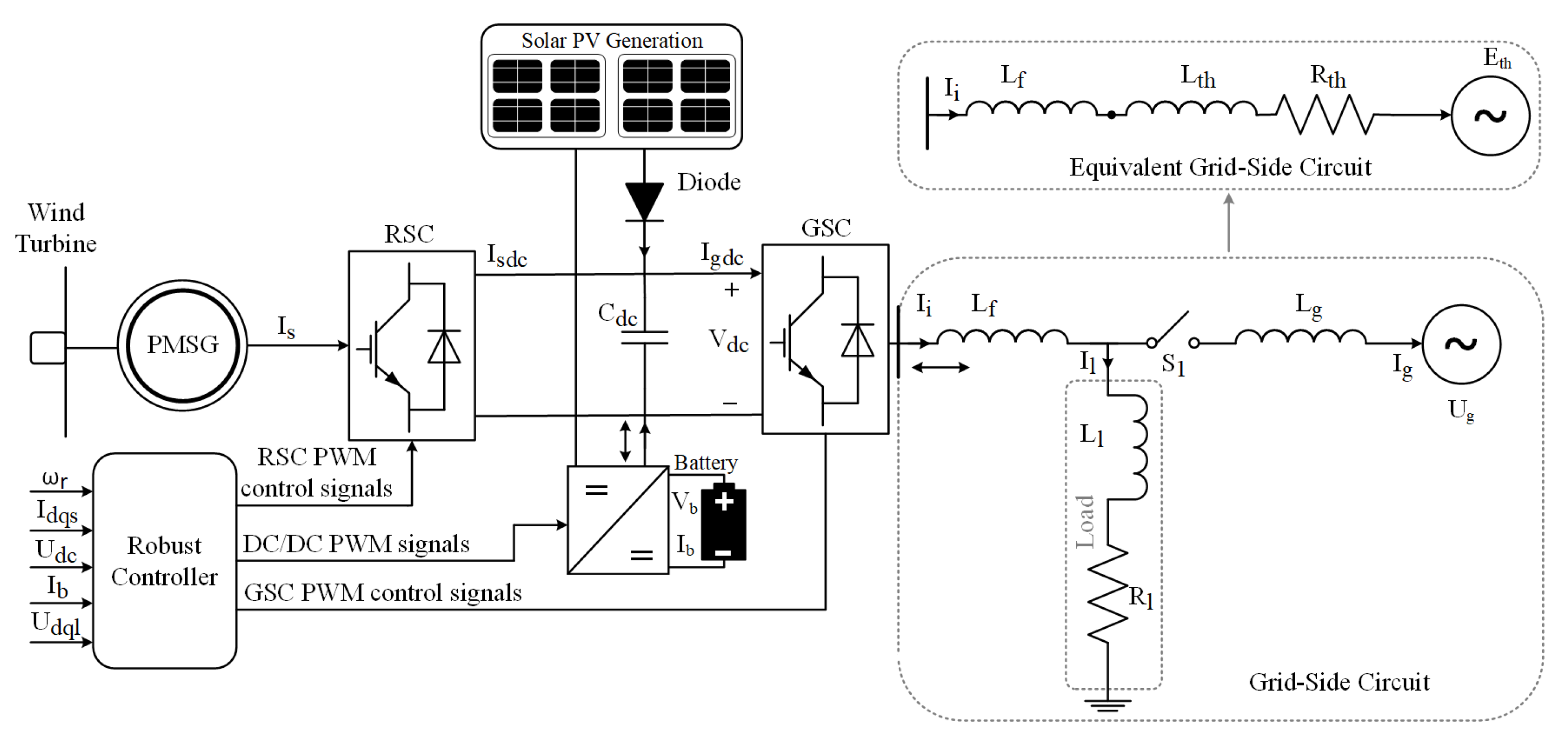
The hybrid renewable microgrid system consists of a PMSG wind turbine, solar PV, battery energy storage system, and load. The microgrid is connected to the utility grid through switch that is placed between the load and the utility network as shown in Figure 1. When the switch between the load and the utility grid is opened, the system is operating in standalone mode and is supplying to the load only. When the switch is closed, the system is in grid-connected mode. The PMSG wind turbine is integrated into the microgrid through the RSC of the B2B converter. The solar PV is directly connected to the DC-bus. A diode is connected in series with the PV array to avert destruction as a result of the reverse flow of current. Similarly, the battery energy storage system is tied to the system at the DC bus and controlled through a DC-DC buck–boost converter.
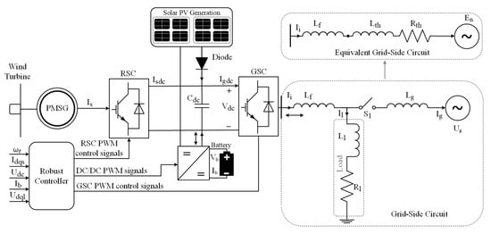
Figure 1.
PV/wind/battery hybrid renewable energy system.
3.1. Wind Turbine Model
The mechanical power () captured by the wind turbine from the wind is given by [48]:
where, is the wind speed, is the power coefficient, is the air density, R is the radius of the wind turbine, is the angular speed of the wind turbine, the tip-speed ratio is represented by , is the pitch angle, J is the inertia of the mechanical shaft, and are the electrical and mechanical torque, respectively.
3.2. PMSG Model
The AC signals from the wind generation system are converted to DC using the RSC. The model of the PMSG is formulated in the d-q reference frame considering the dynamics of the RSC as follows [49]:
where, is the d-axis stator voltage, is the rotor flux, is the stator resistance, is the q-axis stator voltage, is the d-axis self-inducatnce, is the q-axis stator current, is the q-axis stator current, is the q-axis self inductance, and is the stator resistance. For nonsalient PMSG, .
3.3. Modeling of Solar PV Module
The series and parallel connected PV cells formulate the solar PV module that utilizes the solar radiation to generate the DC voltage. In this respect, the equivalent circuit of the PV cell comprises of a series resistor, parallel resistor, diode, and current source. The current output of the solar PV is expressed as [33,50]:
where, is the photo-generated current, is the PV output current, the leakage or reverse saturated current of the diode is denoted by , is the saturated current at the operating temperature of the PV module, and are the number of series and parallel connected PV cells, q is the electron charge, is the diode voltage, A is the p-n junction factor, is the band gap energy of the semiconductor material used in the cell, represents the Boltzmann constant, is short circuit current of the PV module, T is the ambient temperature, is the temperature coefficient, S is the solar irradiance level, is the operating temperature of the PV module, and are the equivalent series resistance and shunt resistance of the PV cell, respectively.
Remark 1.
A number of PV modules are used to obtain a considerable power. The desired reference voltage of the DC-bus (), is obtained from the MPP voltage () of the PV system. When the irradiance is not available, the is replaced by the nominal value of the DC-bus voltage.
3.4. DC-DC Converter and Battery Modelling
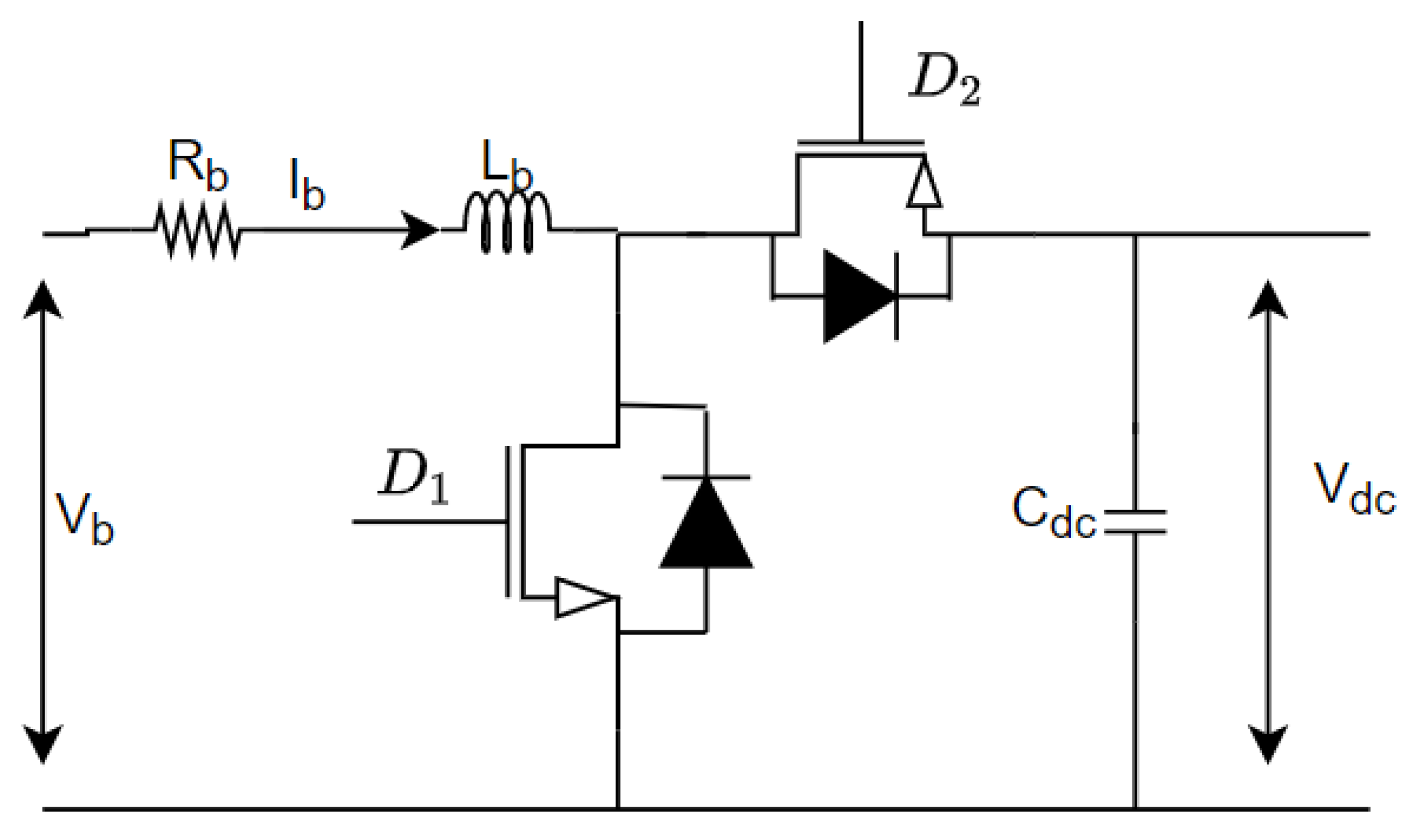
In this study, a Lithium-ion (li-ion) battery is considered as the ESS component in the hybrid renewable microgrid. The ESS is incorporated into the DC-bus of the HRES via a buck/boost converter, as depicted in Figure 2. The converter allows bi-directional operation of the ESS, i.e., during ESS charging it operates as a buck converter and as a boost converter during ESS discharging (13). The converter operates as a buck converter during charging and as boost converter during discharging of the battery. Mathematically, the converter dynamics during the charging mode of the battery is formulated as [51]:
where, is the battery inductance, is the battery current, is the battery voltage, is the internal resistance, is the generated control signal during the charging mode of the battery, is the DC-bus voltage, is the capacitance of the DC-bus, and is the DC current of the GSC converter. Similarly, converter dynamics during the discharging (boost) mode of the battery is expressed as:
where, is the generated control signal during the discharging mode of the battery. Accordingly, standardization can be made to reduce the complexity of the battery model to achieve general formulation using a virtual control (18). Hence, the overall generalized model of the of the battery model (14)–(17) is achieved, that is expressed as:
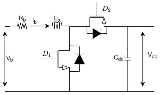
Figure 2.
Buck/boost converter associated with ESS.
The state-of-charge (SoC) of the battery (21) is derived using the battery capacity () and the battery efficiency () [52]. The SoC of the battery is constrained by the lower () and upper () limit of the battery capacity, as follows:
Remark 2.
The solution of (21) is , where is the initial charge of the battery. When the battery is charging, is negative, and the is increasing. On the other hand, when the battery is discharging, is positive, and is decreasing.
3.5. GSC Modeling
The GSC is utilized to convert the DC signals to three-phase AC signals. Accordingly, GSC facilitates the power flow between the ESS and grid enabling the controllability over the load voltage, that is formulated in the d-q reference frame as [53]:
where, and denotes the d-axis and q-axis output voltage of the GSC, respectively, and are the line filter inductance and grid electrical angular speed, respectively, and are the d-axis and q-axis load voltages, respectively, and are the d-axis and q-axis GSC ouput currents.
3.6. Grid Side Modeling
The grid circuit consists of , line inductance (), RL load, switch , and the grid voltage. The leakage inductance of the transformer is included in to simplify the circuit. In order to obtain the expression of the load voltage in terms of the grid voltage, the grid-side circuit is converted to the Thevenin’s equivalent [46].
If the load impedance () and the grid voltage () are given by and , respectively, then the Thevenin’s impedance and voltage are, respectively, expressed as:
where, and are the d-axis and q-axis grid voltages is the load resistance, and is the load inductance. The and are calculated from the power supplied to the load as follows:
where, is the line-to-line root-mean-square voltage. The active power () and the reactive power () of the load are computed using its relationship with the d-axis load voltage () and current () as well as the q-axis load voltage () and current(), as:
The following equations are the d-q-axis representation of the grid side load voltages [46].
where, represents the Thevenin’s resistance, is the Thevenin’s inductance, and are the Thevenin’s voltage in the d-axis and q-axis, respectively.
Remark 3.
When the hybrid microgrid is in standalone mode, and . A robust control law is essential to stabilized the load voltage when the hybrid microgrid is switching between the standalone mode and the grid-connected mode.
3.7. Overall Model of the Hybrid Microgrid
To design a controller that can operate in both standalone and grid-connected modes, the dynamic equations of the components of the hybrid microgrid are expressed in state-space form. The system to be controlled is described by (5)–(7), (19)–(21), (23) and (24). It is an eight-order nonlinear MIMO system that has six control inputs and six controlled outputs. The state variables’ vector, the inputs’ vector, and the controlled outputs’ vector are, respectively, defined as , , and . The dynamic equations of the hybrid microgrid system can be transformed to state-space model as follows [54]:
where
The input–output dynamics of the system is obtained by differentiating each output element of y with respect to time until at least one control input emerges. It is worth noting that has been differentiated twice before the input appears, while each of the remaining controlled outputs has been differentiated once. The input–output dynamics is thus:
where,
The number of differentiation of each output is the relative degree of the output with respect to its input. Therefore, the total relative degree of (32) is 8.
3.8. MPPT Derivation
3.8.1. Wind Turbine MPPT
A P & O scheme is employed for the MPPT operation of the wind turbine. The maximum power point of the wind turbine () can be computed as follows [55]:
By setting , becomes a function of only. Therefore, is obtained as:
Equation (39) can be rewritten as:
From (41), the condition for maximum power is , then the optimal value of the power coefficient () and optimum tip speed ratio () are and , respectively.
3.8.2. PV MPPT
A P & O scheme is employed for the MPPT operation of the PV module. The output power from the PV module () is expressed as:
At MPP, we have [44]:
Maximum power is extracted from the PV using the formulated MPP, that determines the corresponding DC-link voltage of the PVs. Similarly, the current enhanced centralized power converters enable direct integration of PVs ensuring power quality standard of operation [33].
4. Power Management
To prevent power shortage and damage of the microgrid components due to excess power, an energy management system is designed to coordinate the power flow between the grid power (), , , battery power (), and the active load demand (). The power balance equation for the hybrid microgrid is written as:
It is worth noting that
The net power in the system can be computed as:
The charging and discharging modes of the battery depend on . When , the excess power generated is transferred to the battery (charging mode) provided that . When , the power shortage is compensated by discharging battery power to the load provided that , otherwise load shedding is needed to maintain power balance.
5. Control Design
In this section, the nonlinear MIMO robust control of the hybrid microgrid system is designed. The presented control scheme works satisfactorily even under changing solar irradiation and varying wind speed. The control objectives are outlined as follows:
- Harnessing the maximum power from the wind by optimally regulating the rotor speed, , to track the wind speed variations.
- Achieving a unity power factor operation at the PMSG stator terminals by controlling .
- MPPT operation of the PV module by controlling .
- Meet the load voltage requirement by controlling the and .
- Ensuring a smooth power management between the renewable energy sources, storage system, load and grid by controlling .
- Regulating the DC-bus voltage by controlling .
Calculation of the Reference Signals
The reference variables for , , , , , and are set as , , , , , and , respectively. The reference values are calculated as follows [55]:
- The is computed as follows:
- The can be generated as follows: The stator’s power factor angle must remain zero in order to obtain unity power factor. The PMSG’s stator current angle and voltage phase angle are expressed by the following equations [56]:Subsequently, is computed such that the following condition is satisfied.The value of is thus:
- is selected to be equal to the grid voltage so that the grid can easily synchronize with the microgrid at the point of common coupling.
- is selected such that the reactive power is very close to zero. It is calculated as follows:Assuming the GSC is ideal, then the active power along the two sides of the GSC are equal.Remark 4.Note that is the power received by the grid from the GSC as explained in (46) and is the control input of .From (53), can be derived as follows:
- is calculated by dividing in (47) with as follows:
- is set as the MPPT voltage of the PV module (). However, when the solar irradiance is low, is set as the nominal voltage of the DC-bus. The nominal value of the DC-bus voltage is calculated as [57]:where is the modulation index.
The tracking errors are given as follows:
The sliding mode surfaces are defined as:
where , , and are positive constants. The time derivative of (63) yields:
Define the vector . Then, (64) can be evaluated as follows:
The output variables will converge toward their respective sliding mode surfaces and provide the desired steady-state performance by staying on the surfaces provided that . The equivalent control input vector can be obtained by canceling the terms on the right-hand side of (65).
Since , (66) is well defined. In order to compensate the external disturbances and parametric uncertainties, a switching control input vector is given by:
where is a positive definite diagonal matrix, and .
The robust control input vector is given by:
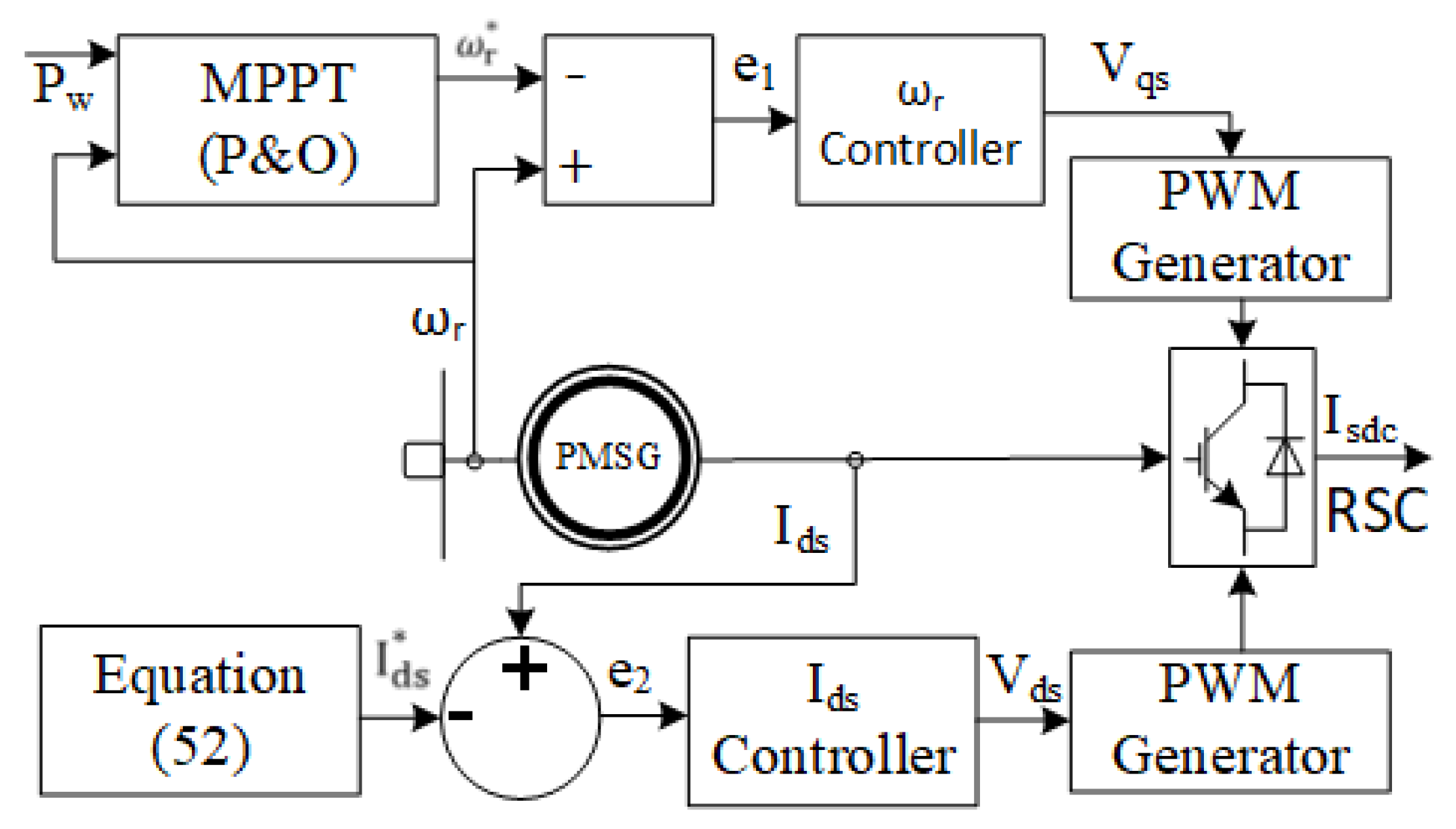
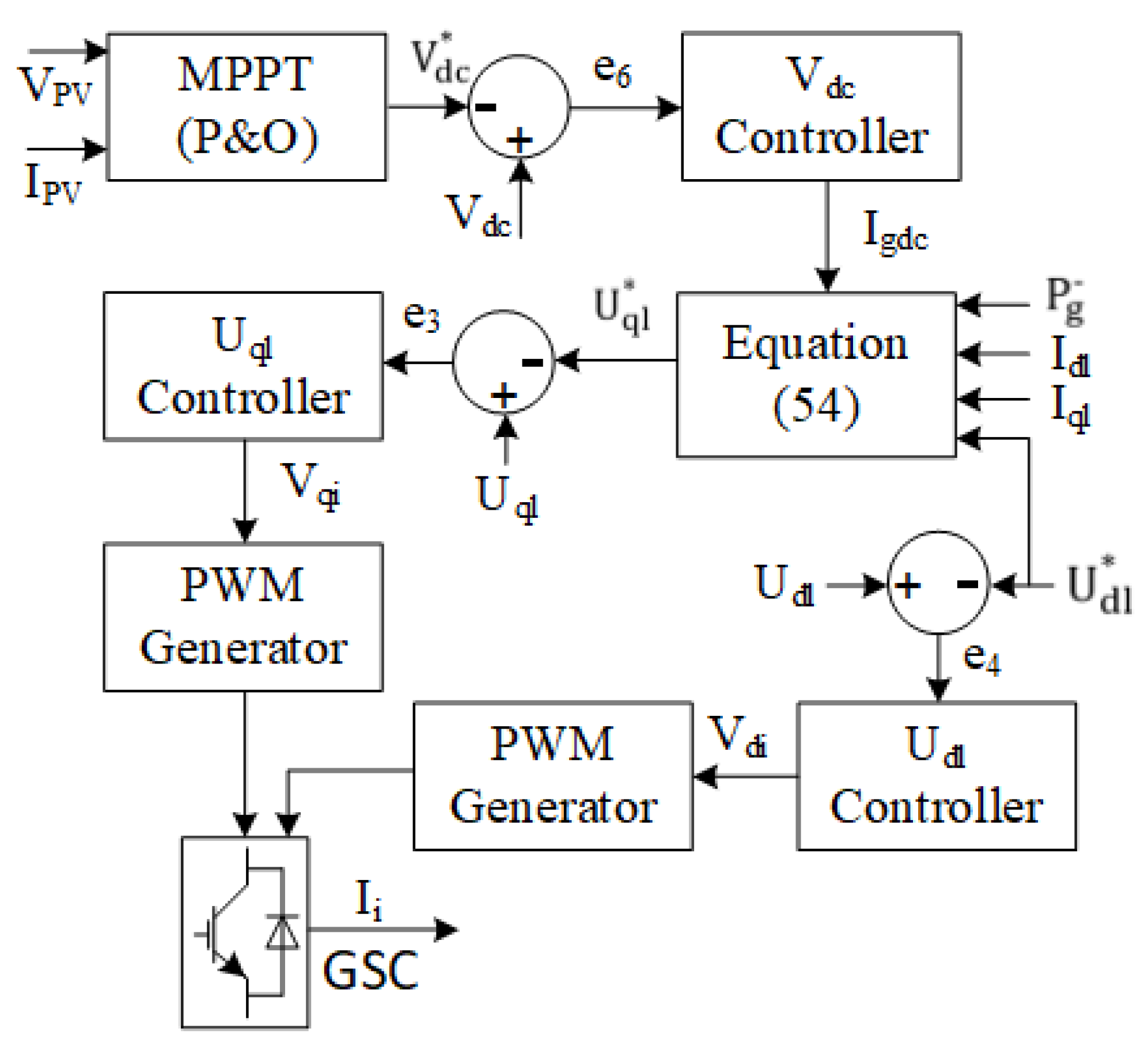
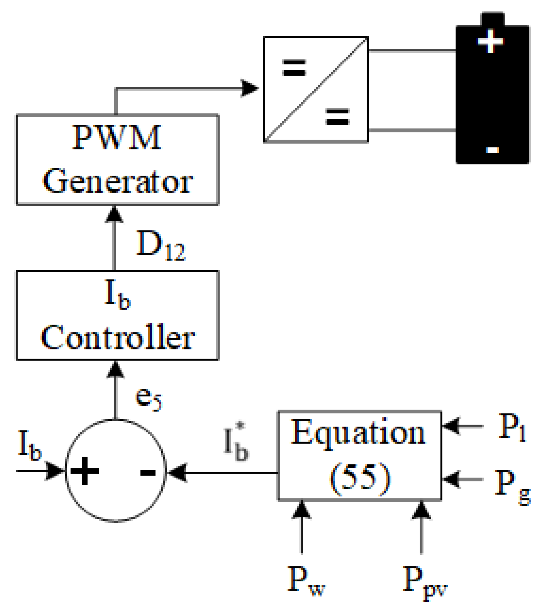
Figure 3 illustrates the RSC control for MPPT performance of the wind turbine and wind power transfer with unity power factor. The GSC control scheme has a cascaded control structure as shown in Figure 4. It consists of an outer DC-bus voltage controller and an inner loop controller to provide the pulse width modulation signals to the GSC. Additionally, is controlled through the GSC. Figure 5 depicts the control scheme for the ESS buck/boost converter. The controller adjusts the duty cycle of the buck/boost converter for charging/discharging operation of the ESS to balance the power.
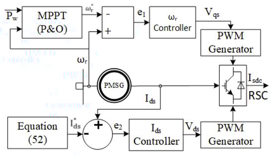
Figure 3.
Control diagram of the RSC.
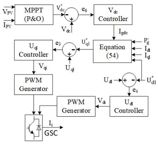
Figure 4.
Control diagram of the GSC.
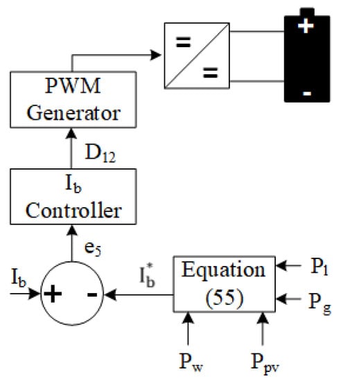
Figure 5.
Control diagram of the buck/boost converter.
The state trajectories of the hybrid microgrid system achieves asymptotic convergence based on the sliding mode surfaces (63) and the robust control inputs (68).
Proof.
Consider the following candidate Lyapunov function:
The time derivative of L yields:
Taking the norm of (71) gives:
□
Therefore, the closed-loop system is asymptotically stable.
6. Simulation Results
The hybrid microgrid system was developed on Matlab/Simulink environment using a time-domain simulation model. The harmonic effects of the converter have not been considered in this study. The system comprises of a number of PV module arranged in series and parallel to obtain a considerable output power of MW, a nonsalient pole variable speed PMSG with rated power of 2.45 MW is deployed as the generator, and a li-ion battery is employed as the ESS. A discharging constraint of and charging constraint of is employed to restrict ESS degradation [58,59]. The parameters of the renewable generators and ESS are given in Table 1 and Table 2, respectively.

Table 1.
Parameters of the renewable generation system [44,60].
Table 2.
Grid and energy storage parameters.
The performance of the proposed controller is evaluated based on external and internal disturbances experienced in the HRES. The variations in renewable power and load demand are considered as the external disturbances and the internal disturbances includes a parametric uncertainty of that is introduced into the nominal parameters of the HRES components namely, on J, , , , and . The controller gains are chosen as , , , and , , , , and .
Two case studies have been investigated. In case 1, a random wind speed profile, a constant solar irradiation level and load variation are considered. In case 2, step changing wind speed profile, varying solar irradiation, and load variation are considered.
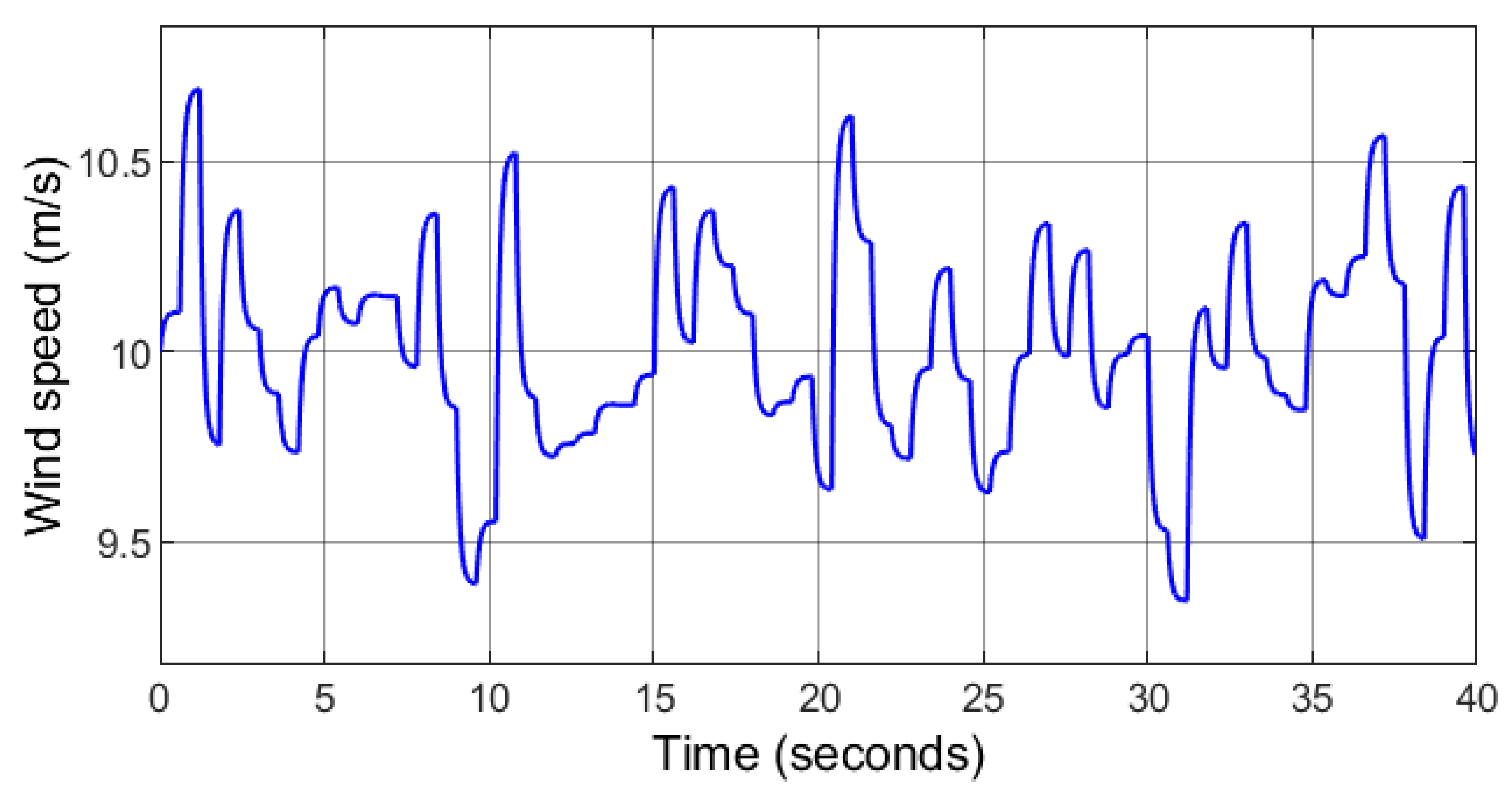
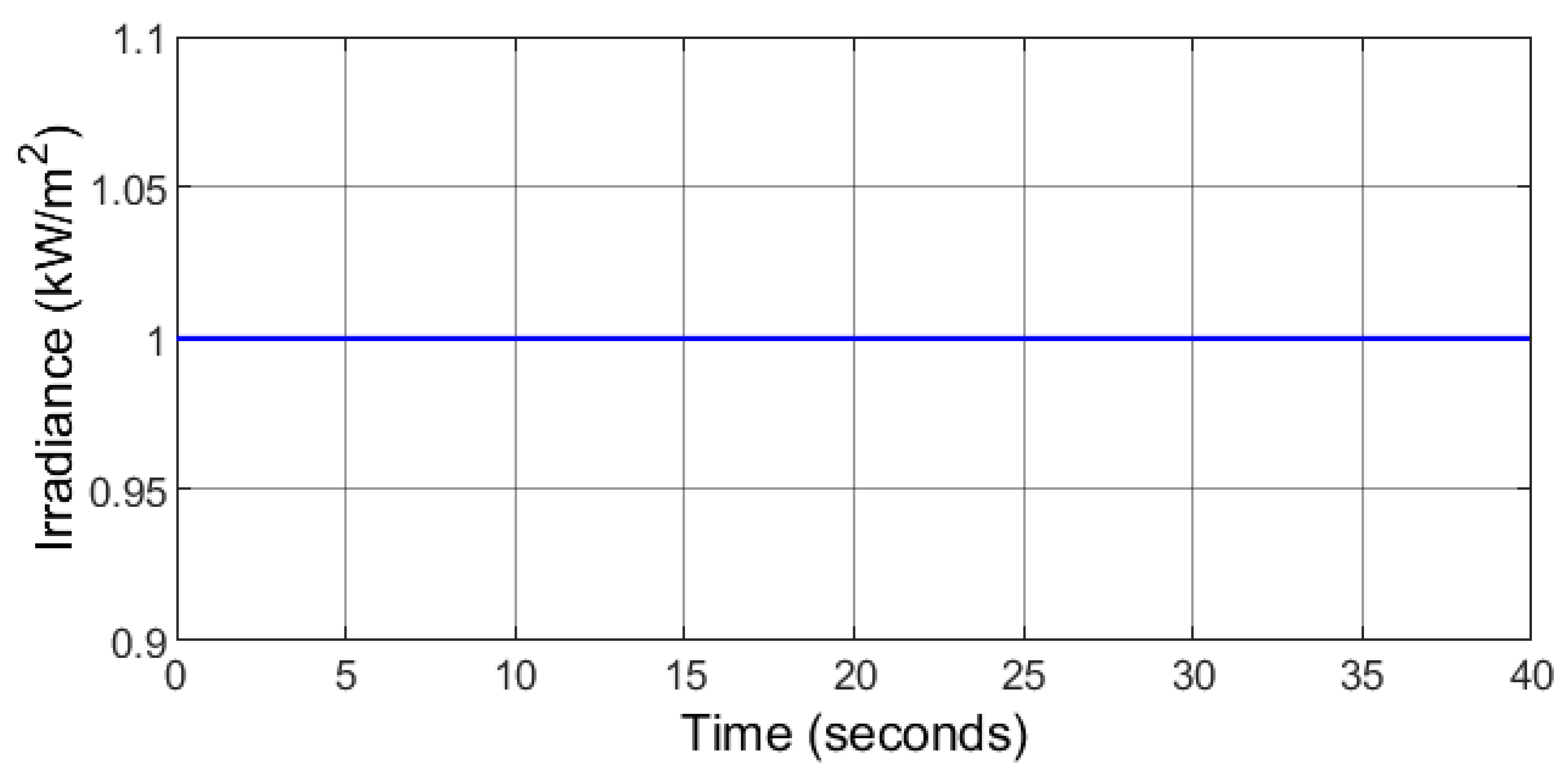
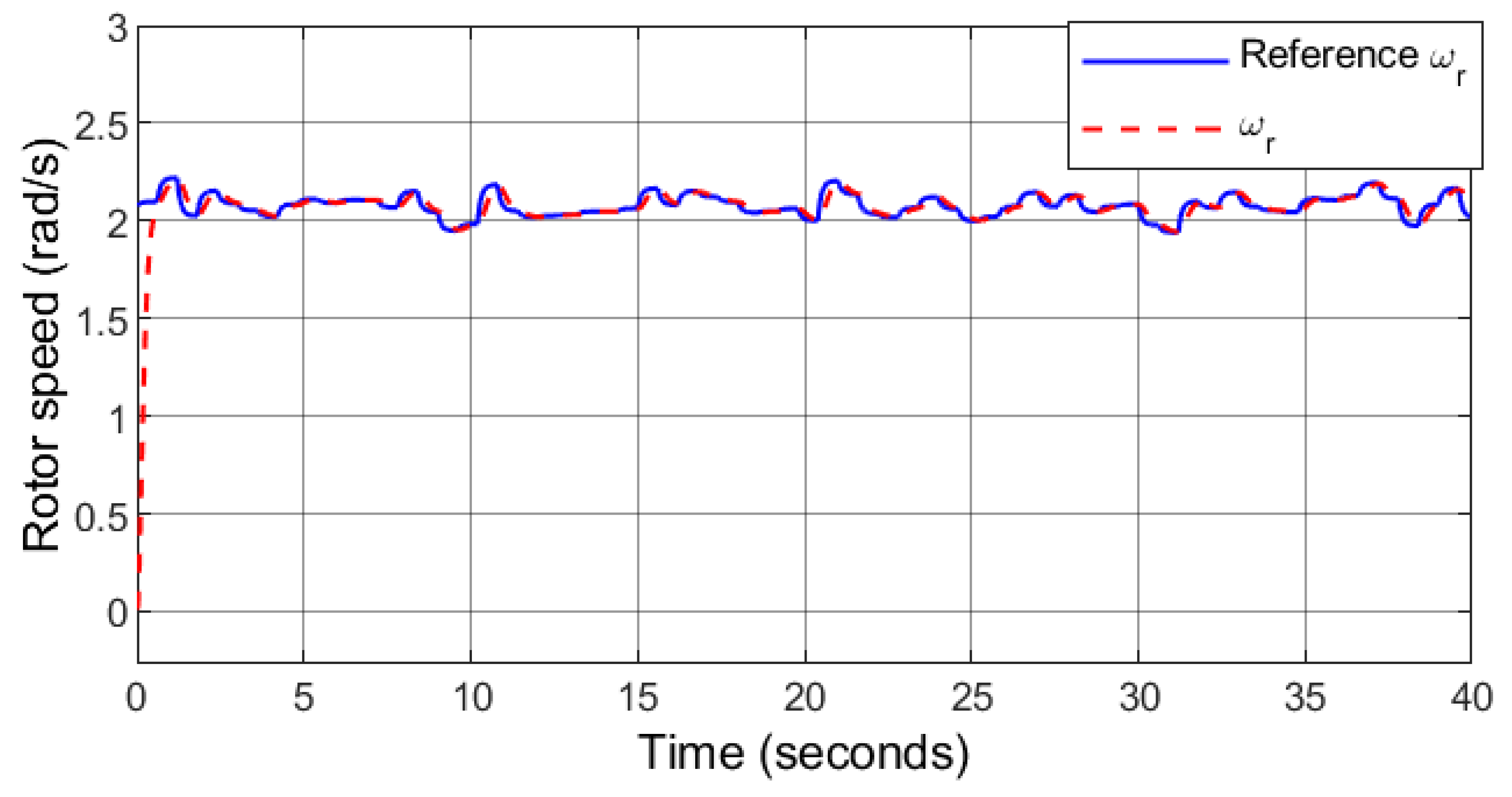
6.1. Case 1: Random Wind and Fixed Solar with Varying Load
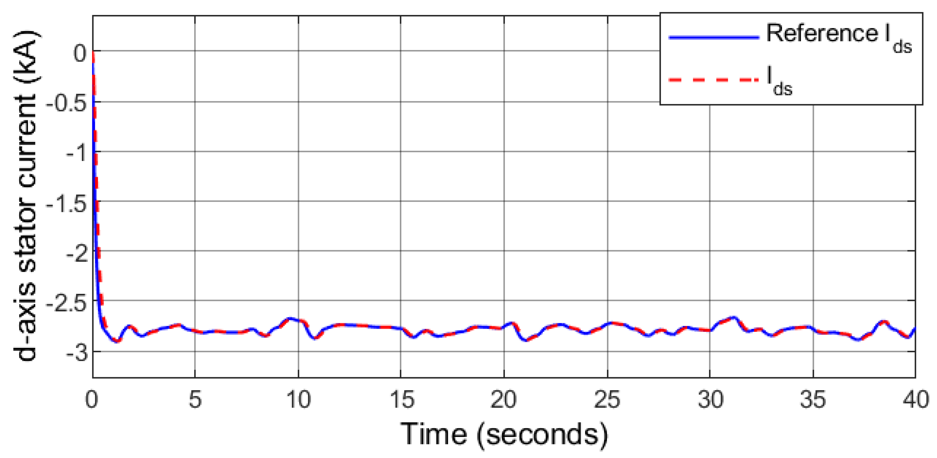
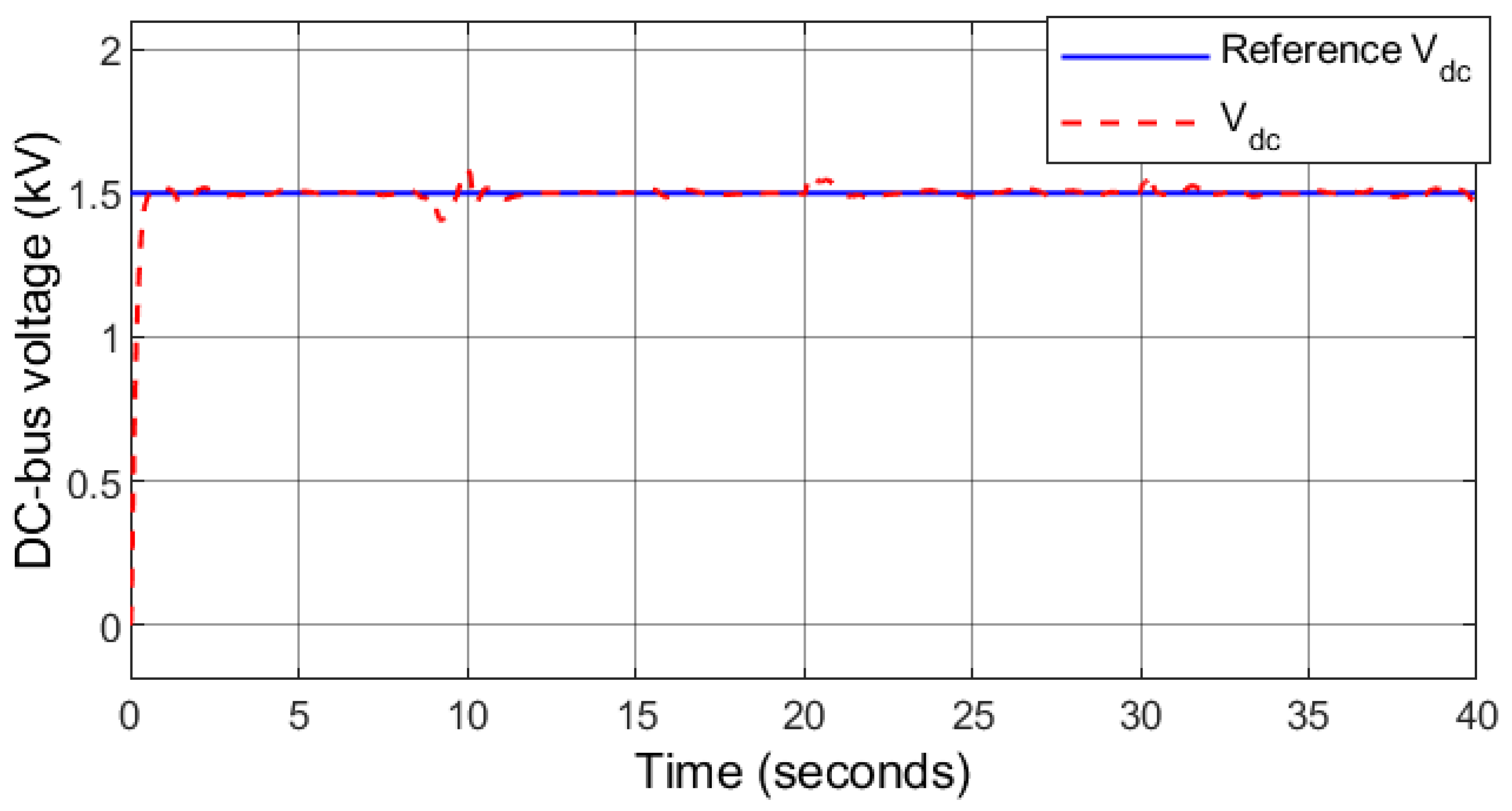
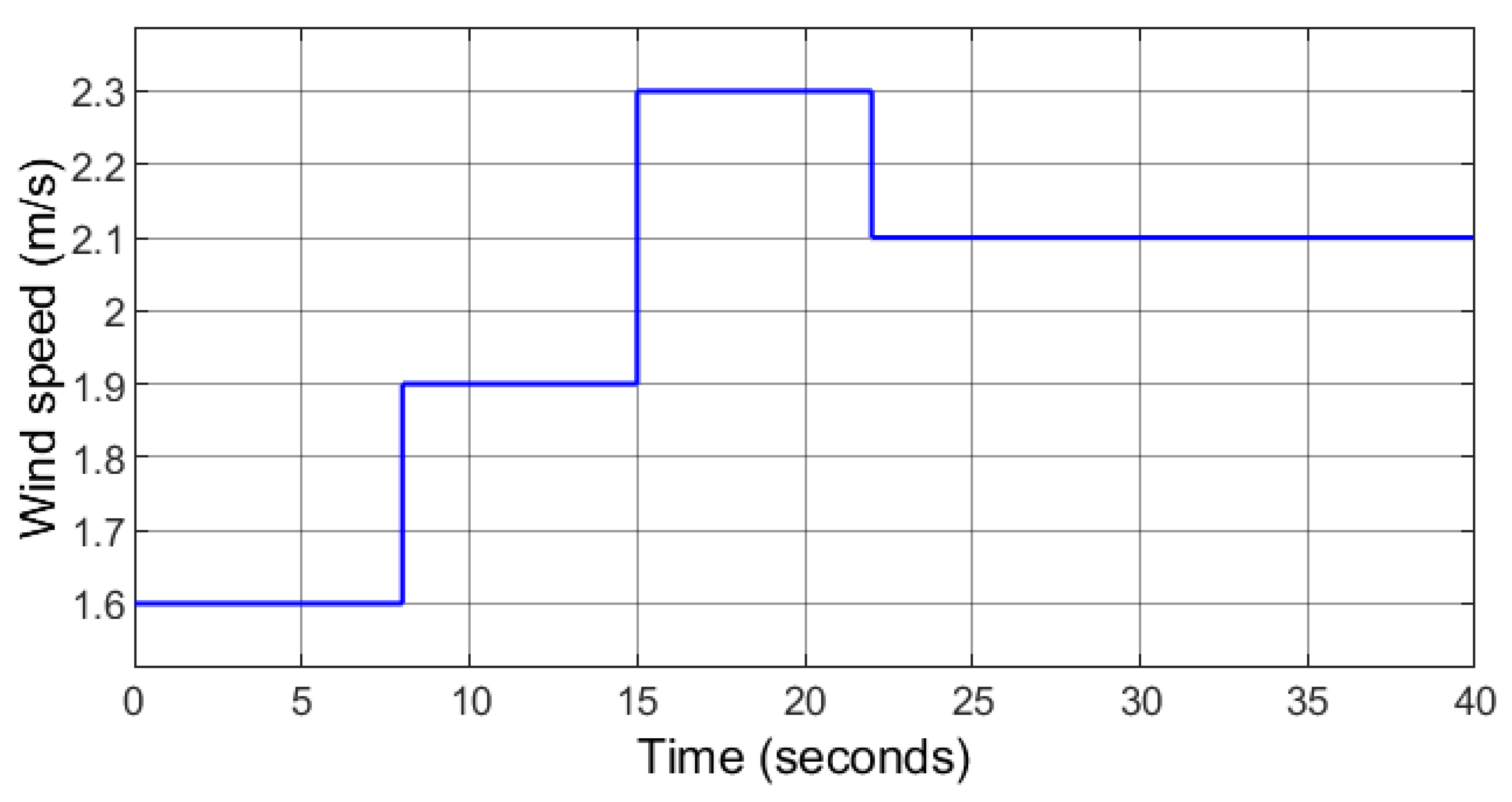
The wind speed comprises of a random profile (Figure 6), 1000 W/m2 solar irradiance is fixed (Figure 7). Figure 8 depicts the optimal tracking performance of the rotor speed. It can be seen that the proposed controller closely tracks the optimal rotor speed calculated by the MPPT so that maximum power is produced by the PMSG. The response of the d-axis stator current for unity power factor operation is depicted in Figure 9. The DC-bus is receiving contribution from the solar PV, the wind power generator, and the ESS. The response of the DC-bus voltage together with the reference value which is the same as the MPPT voltage of the solar PV is shown in Figure 10. The controller can keep the DC-bus voltage stable and very close to the reference value despite the variation of the wind power, the ESS power, and the load demand.
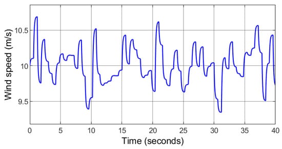
Figure 6.
Case 1: Random wind speed profile.

Figure 7.
Case 1: Constant solar irradiation.
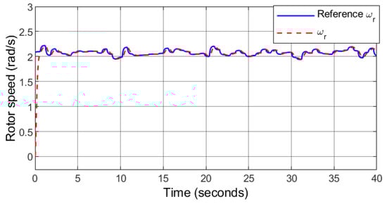
Figure 8.
Case 1: Rotor speed.

Figure 9.
Case 1: d-axis stator current.
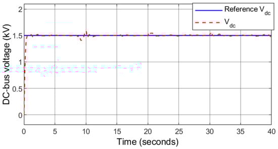
Figure 10.
Case 1: DC-bus voltage.
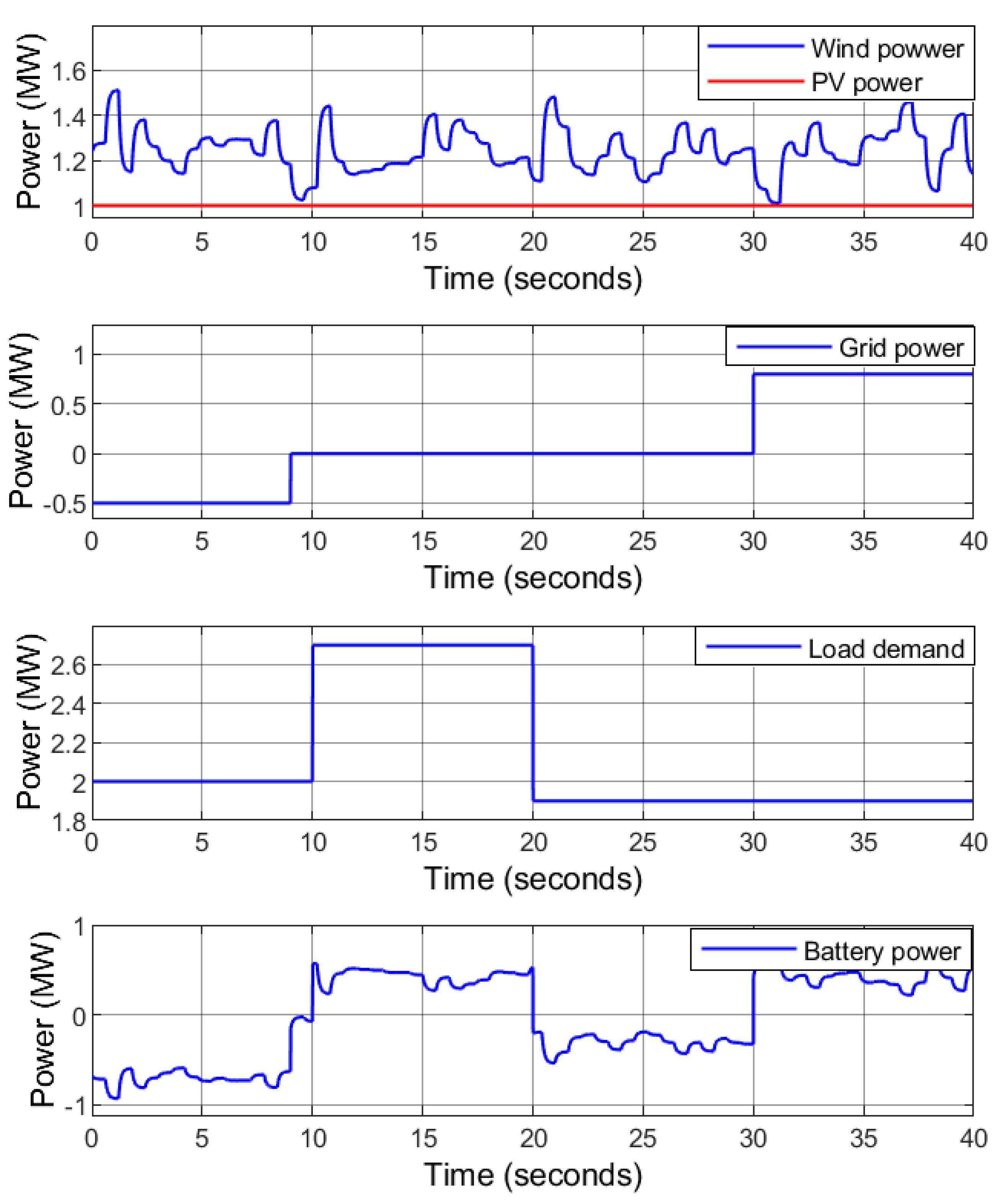
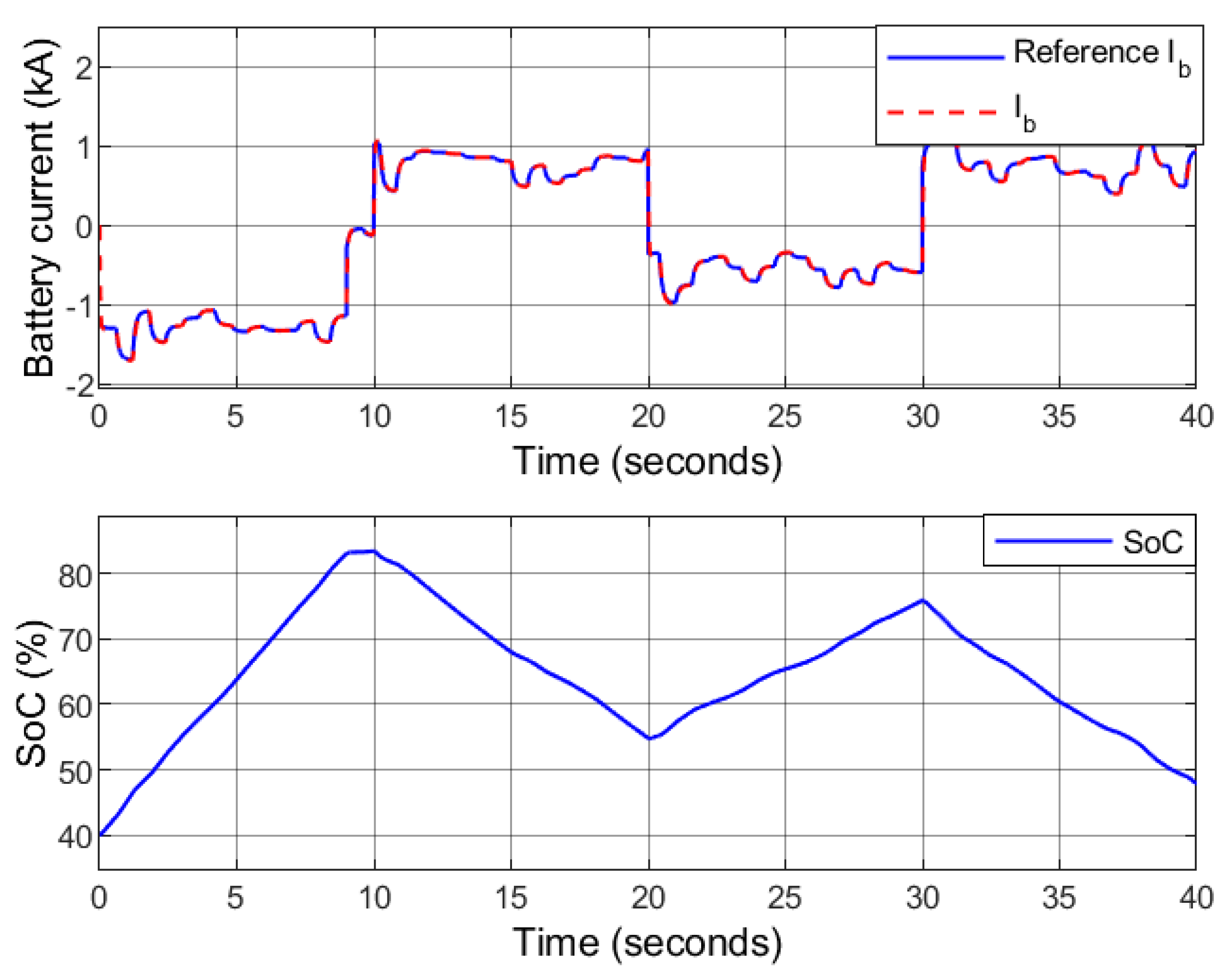
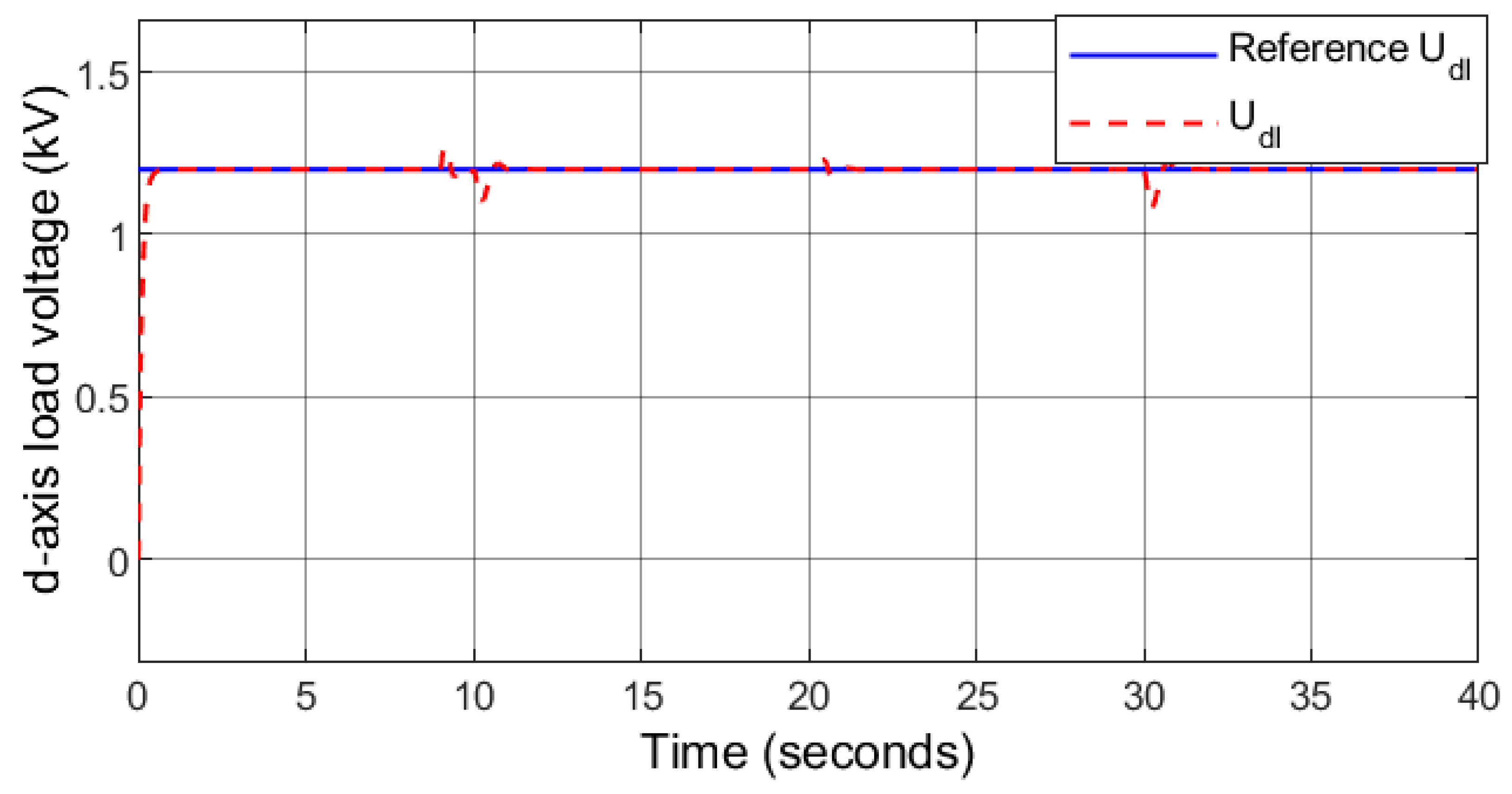
As shown in Figure 11, an increment in the load demand at s is experienced that rises from 2 MW to MW, and further decreases to MW at s. The grid is receiving and sending power at 0 s < t ≤ 9 s and 30 s < t ≤ 40 s, respectively, and the hybrid microgrid is off-grid at 9 s < t ≤ 30 s. In order to maintain the power flow, the battery is charging to store the excess power at 0 < t ≤ 10 s and 20 s < t ≤ 30 s. Similarly, the battery is discharging to the load at 10 s < t ≤ 20 s and 30 s < t ≤ 40 s. Figure 12 indicates that the battery is charging/discharging according to the desired level to balance the power in the microgrid within the acceptable SoC limit. An increment in load voltage is experienced at s due to off-grid operation of the HRES during power receiving mode and at s due decrease in load demand. Similarly, the load voltage decreases at s due to the increase in the load demand and at s due to connection of the grid to the HRES during the power transferring mode (Figure 13 and Figure 14).
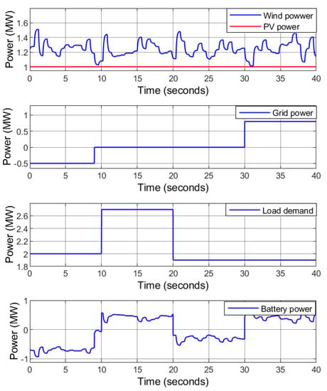
Figure 11.
Case 1: Power flow.
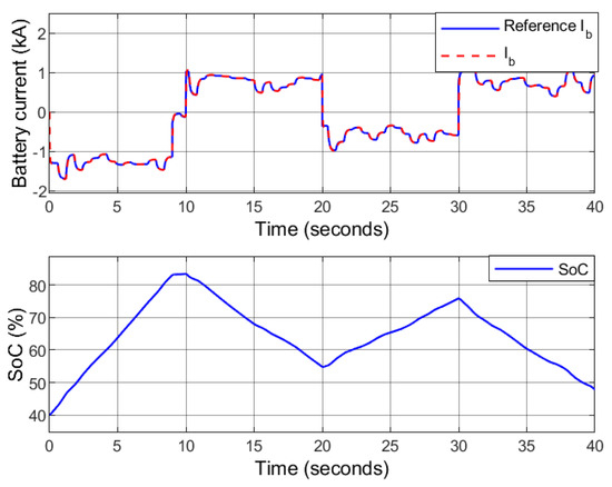
Figure 12.
Case 1: The battery current (above) and the SoC (below).
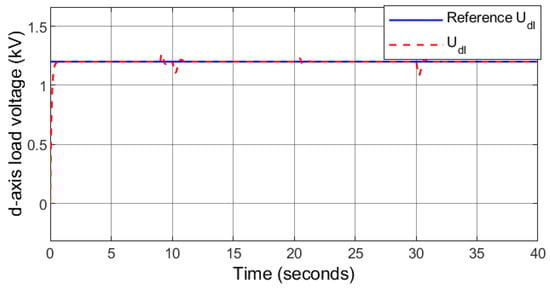
Figure 13.
Case 1: d-axis load voltage.
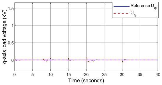
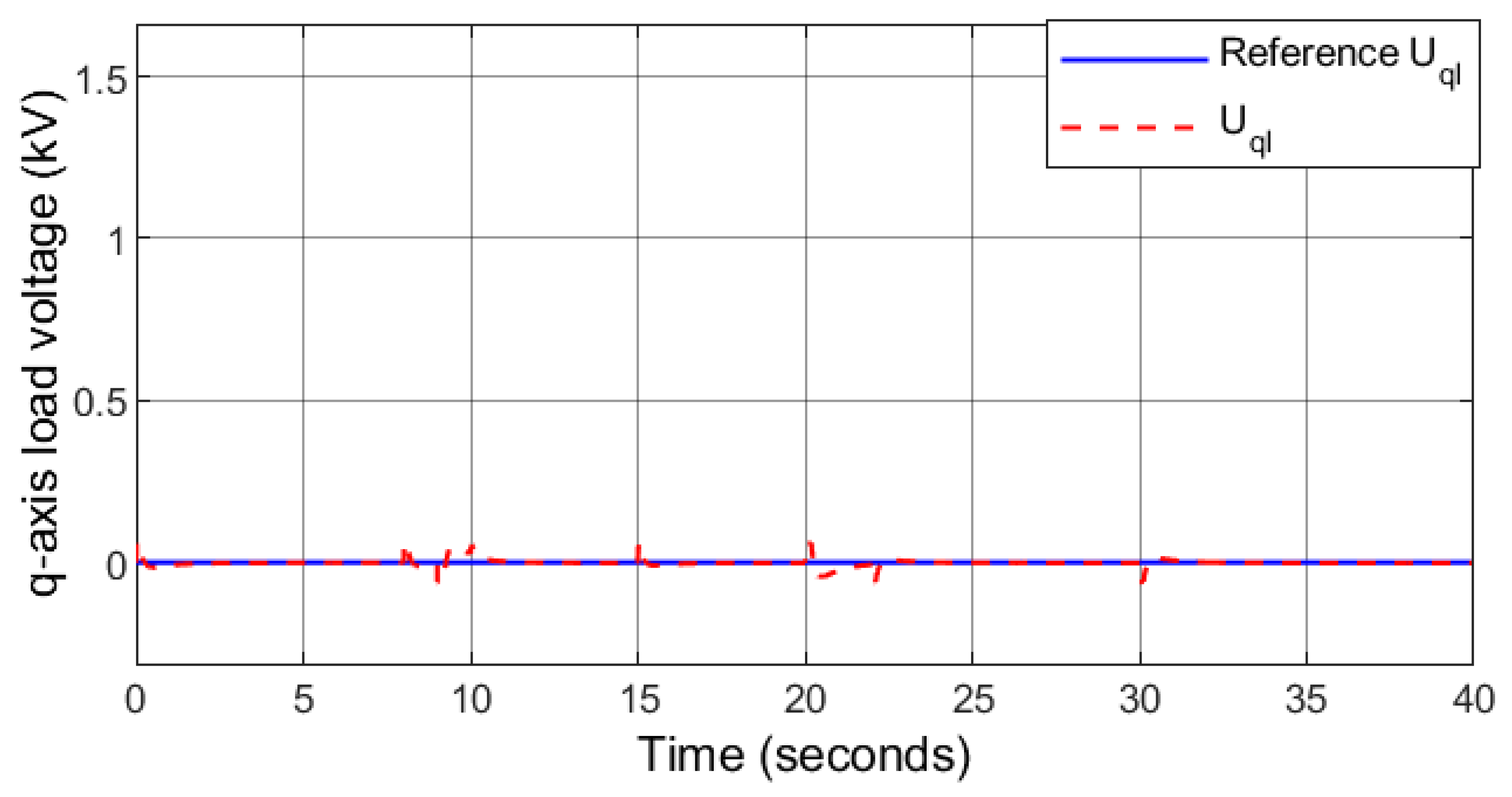
Figure 14.
Case 1: q-axis load voltages.
It can be observed that the controller can restore the load voltage to the desired level regardless of the load demand variations and at the transition intervals of the HRES between the standalone and grid-connected modes. Moreover, the controller keeps close to zero to minimize the reactive power. The transition of the system from islanded to grid-connected mode and vice-versa are smooth due to the robustness and accuracy of the proposed controller.
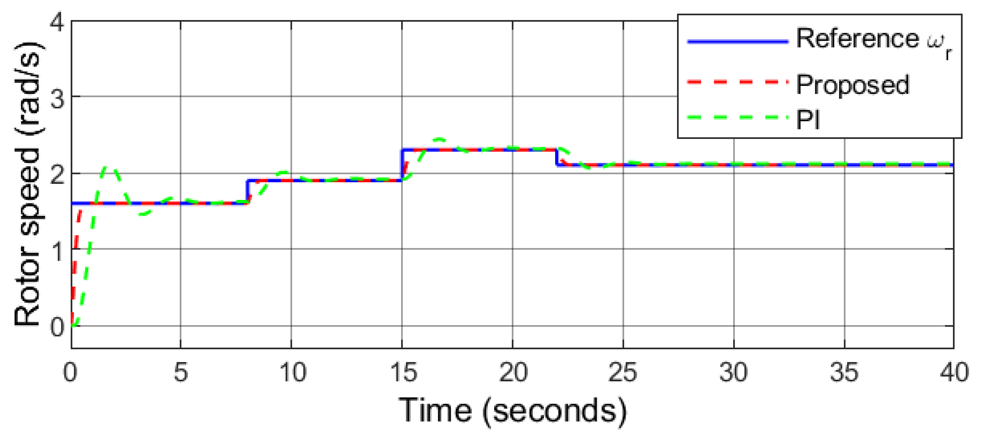
6.2. Case 2: Step Change in Wind and Solar with Varying Load
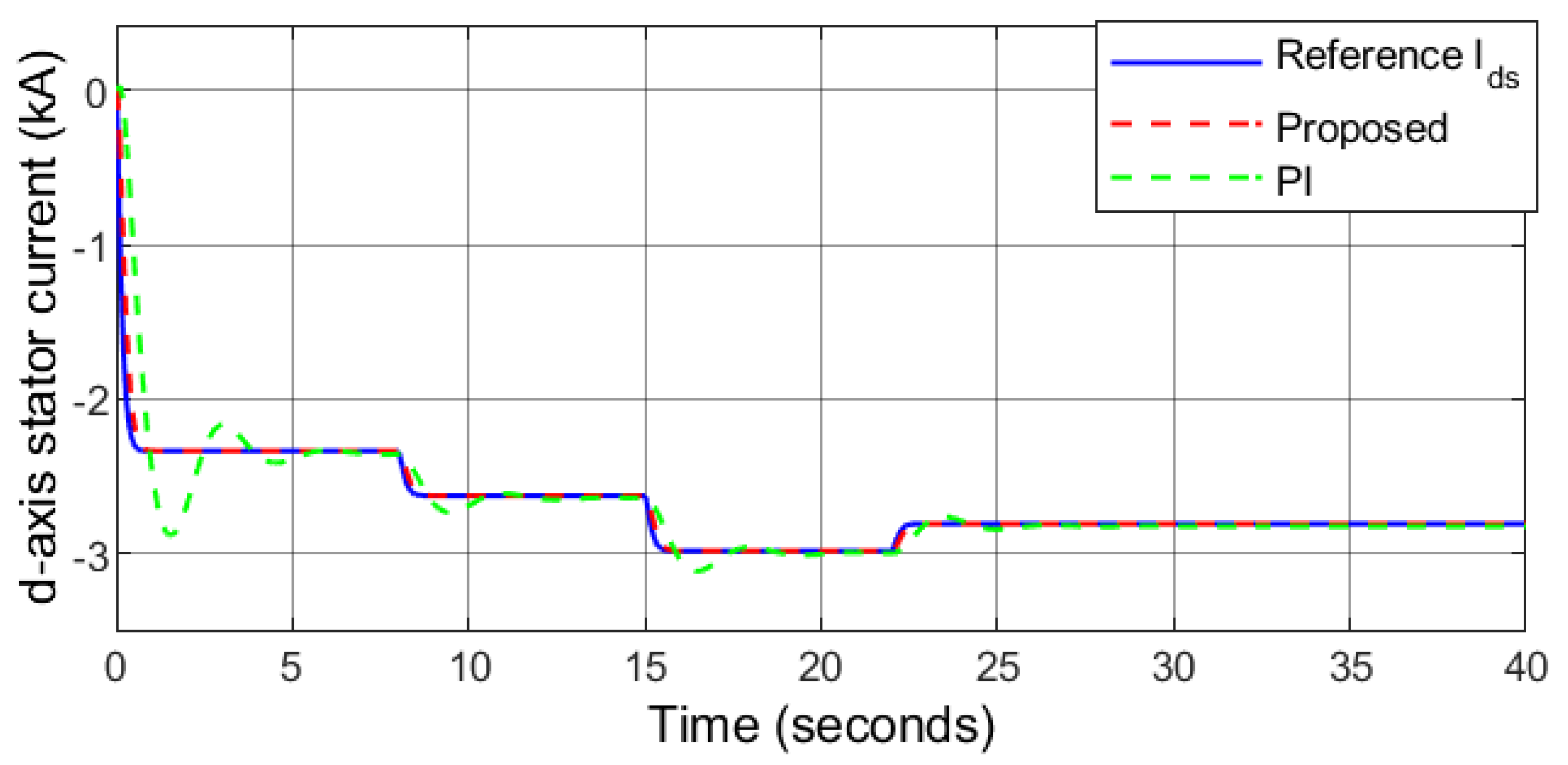
In this case, a step changing wind speed profile and solar irradiance level are considered. As depicted in Figure 15, the wind speed rises from 7.7 m/s to 9.2 m/s, 11 m/s and finally decreases to 10.1 m/s at and 22 s, respectively. The solar irradiance level decreases from 1000 W/m2 to 965 W/m2, 933 W/m2 and finally increases to 1000 W/m2 at s, 15 s and 20 s, respectively (Figure 16). The rotor speed follows the desired speed under varying wind conditions (Figure 17), which indicates that the PMSG is rotating at the optimal speed computed by the MPPT algorithm ensuring maximum power generation under variable wind speed. The d-axis stator current tracks the desired current accurately as depicted in Figure 18, that allows wind power transfer with a unity power factor. Furthermore, results obtained using PI controller is also presented in this section. The comparative analysis highlights the performance between the proposed controller and benchmark PI control technique [33] based on the calculated optimal values of , , , , , and .
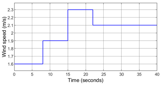
Figure 15.
Case 2: Random wind speed profile.
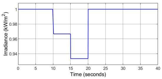
Figure 16.
Case 2: Varying solar irradiation.
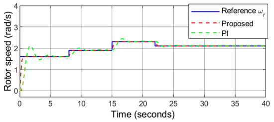
Figure 17.
Case 2: Rotor speed.
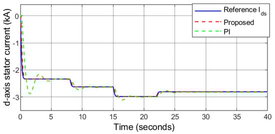
Figure 18.
Case 2: d-axis stator current.
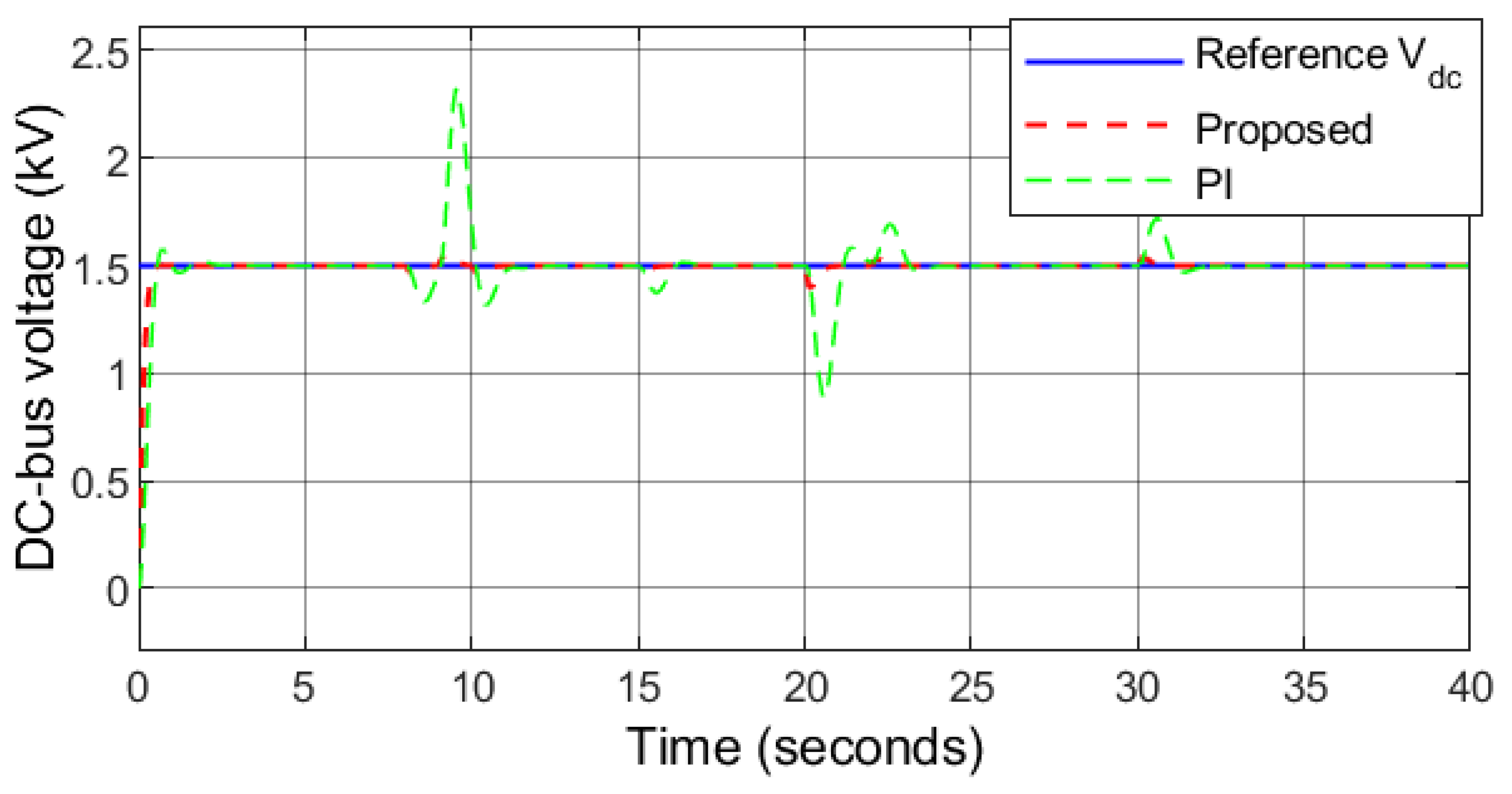
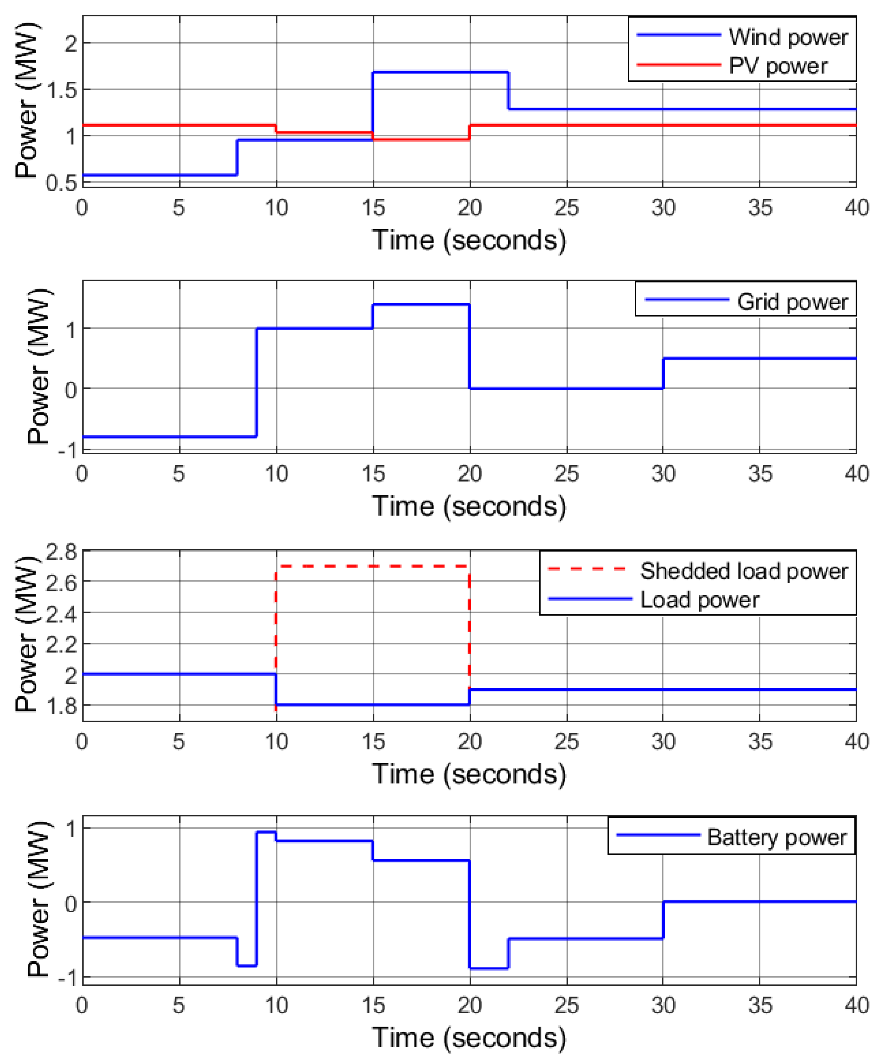
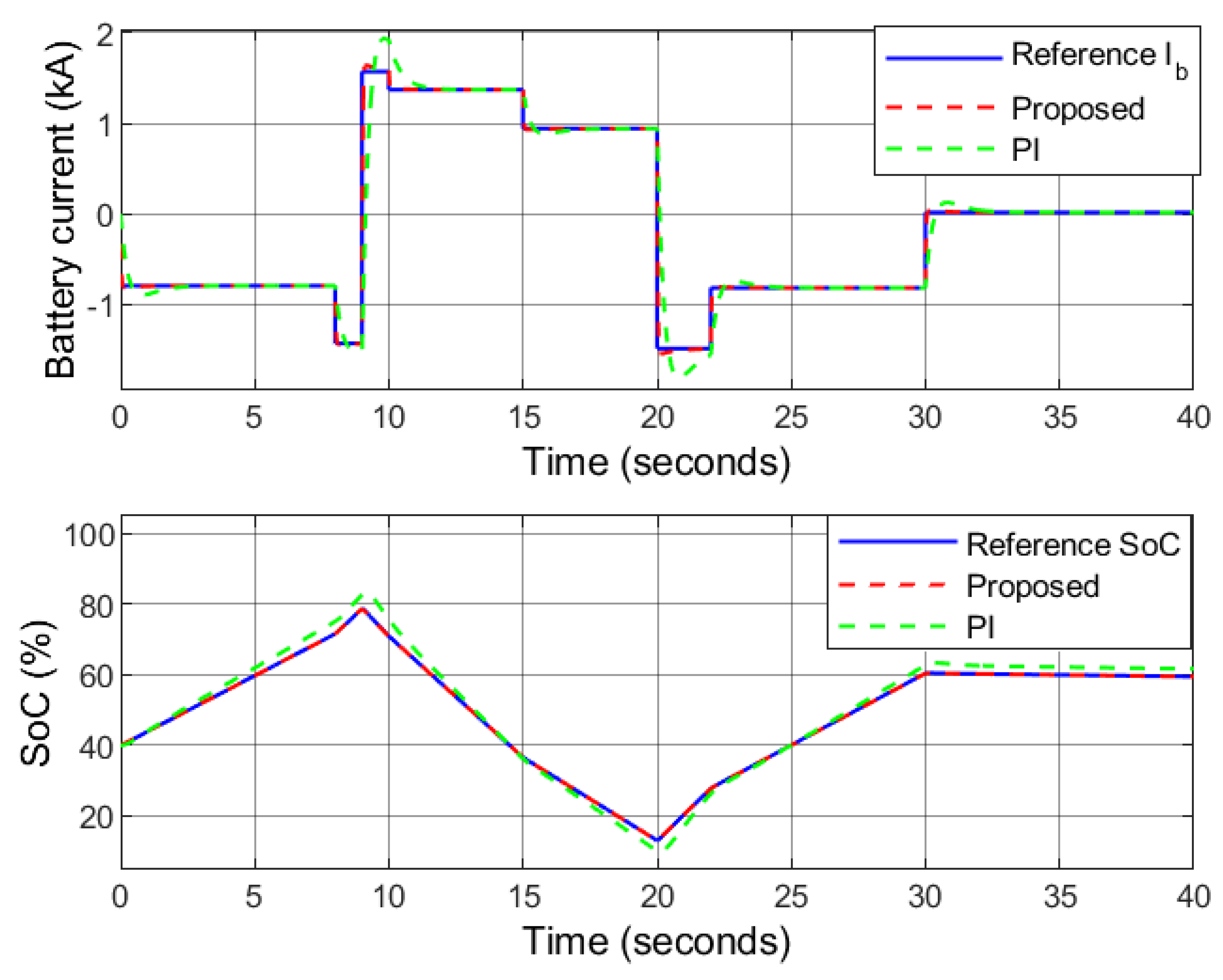
The irradiance level falls to 965 W/m2 and 933 W/m2 at . During this interval, the PV MPPT voltage also falls, and thus the reference DC-bus voltage is set as the nominal value instead of the PV MPPT voltage to maintain a constant DC-bus voltage. It can be observed that the proposed controller keeps the DC-bus voltage stable and constant value under varying PV power, wind power, and load demand as depicted in Figure 19. The load demand profile is similar to case 1 as shown in Figure 20. The utility grid is receiving power at and sending power at and . The HRES is off-grid at . When and , the surplus power is transferred to the battery. When , the battery is unable to cover the power deficit as the maximum power it can safely deliver is 1 MW. As a result, 0.9 MW of the load demand is shedded for protecting the battery and maintain the power balance of the HRES.
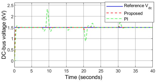
Figure 19.
Case 2: DC-bus voltage.
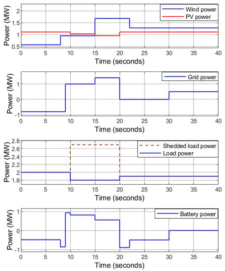
Figure 20.
Case 2: Power flow.
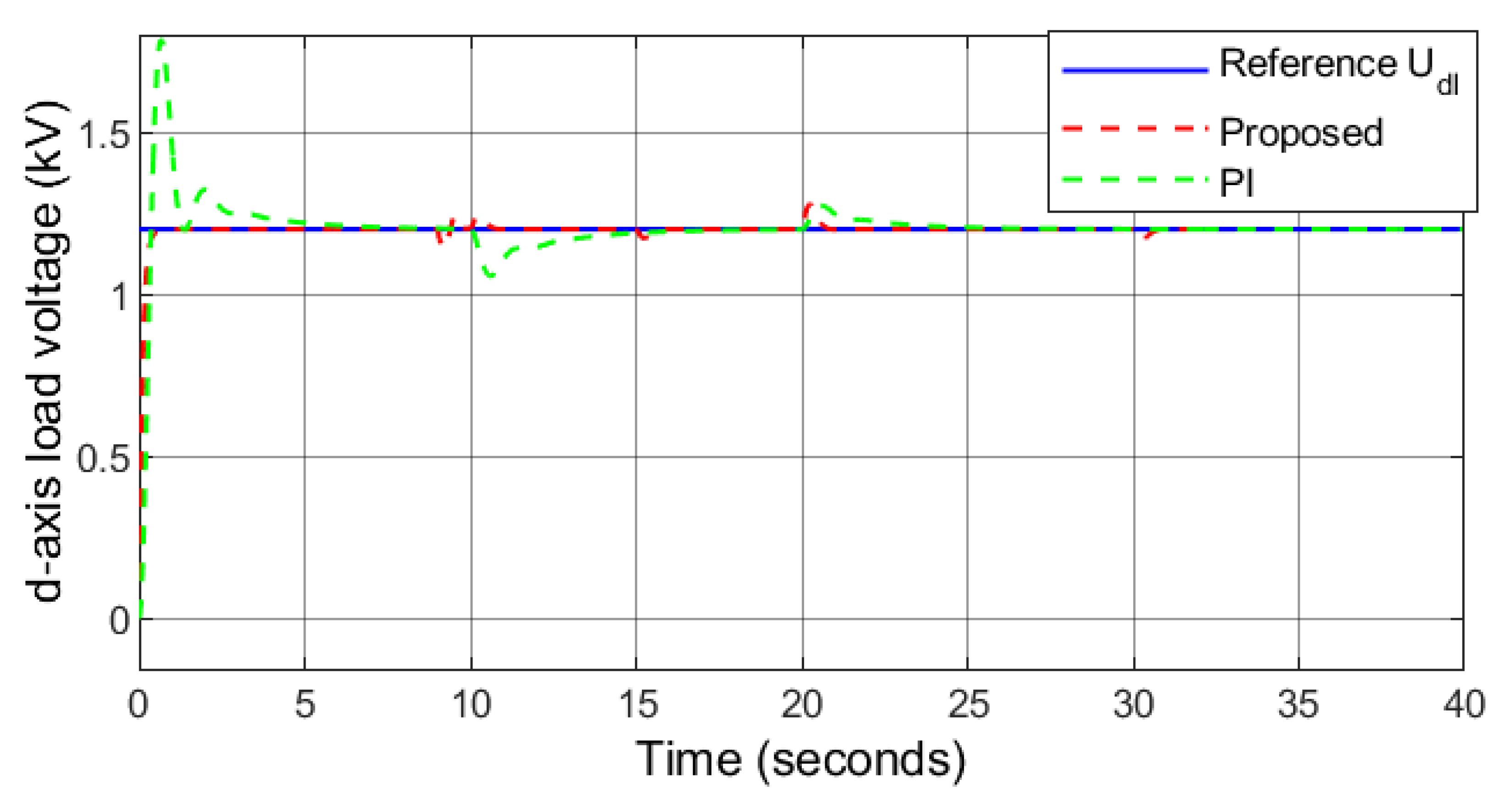
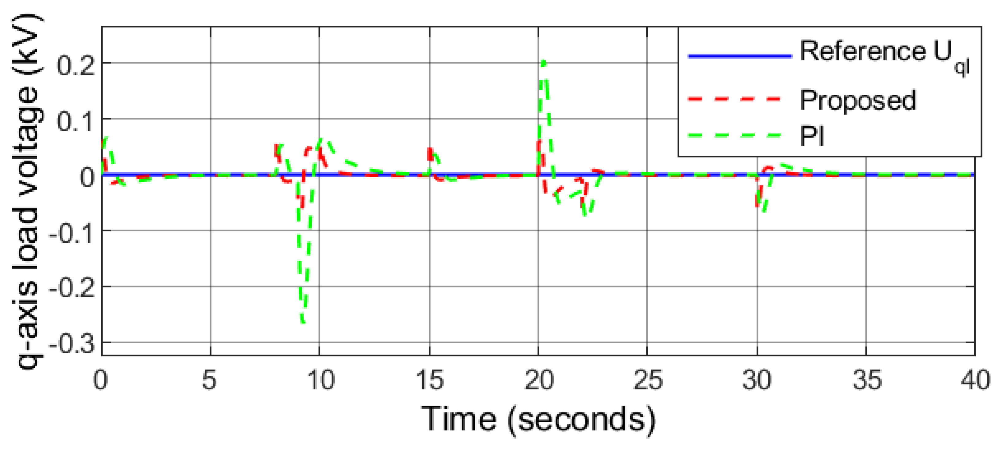
Figure 21 describes that the ESS is charging/discharging in accordance with the demand to balance the microgrid. Accordingly, the power flow is balanced and no power is transferred into or out of the battery and its SoC remains constant (60%) at . The load voltage is kept at a constant level by the proposed controller as depicted in Figure 22 and Figure 23. In addition, converges to zero, thereby minimizing the reactive power. It can be observed that the effects of varying load demand, grid transition from power receiving mode to power transferring mode, and grid transition from islanded mode to grid-connected mode and vice versa are mitigated by the proposed controller.
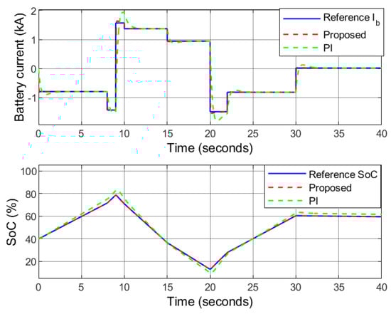
Figure 21.
Case 2: Battery current.
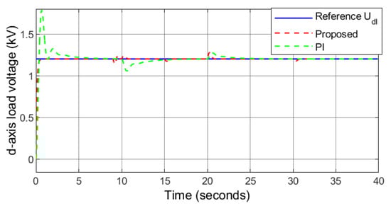
Figure 22.
Case 2: d-axis load voltage.
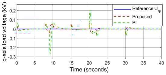
Figure 23.
Case 2: q-axis load voltage.
The performance of the benchmark PI controller proves to have an acceptable performance under external disturbances. The performance of the PI controller in this condition is compared with that of the proposed robust sliding mode controller. The analytical results are depicted in Figure 17, Figure 18, Figure 19, Figure 20, Figure 21, Figure 22 and Figure 23. It can be observed that the responses of the proposed controller in following the reference signals are quite satisfactory as they reach them in , , , , , and for , , , , , and , respectively. However, the responses under PI controller have comparatively higher overshoots, undershoots, and longer settling time highlighting the effectiveness of the proposed controller.
7. Conclusions
This paper presented an integrated control and power management of a hybrid renewable energy system (HRES) under different external generation/load disturbances and internal parameter uncertainties for both standalone and grid-connected operational modes. The HRES consists of solar PV, wind energy source, and battery. The proposed robust sliding mode control successfully achieves maximum power point tracking (MPPT) for both the solar PV and wind energy sources while regulating the load voltages and maintaining the DC-bus voltage at 1.5 kV. The stability and convergence of the closed-loop system have been guaranteed using the Lyapunov candidate function. Furthermore, a comparative analysis is presented with a conventional PI-based controller. The results obtained highlight a significantly improved robustness and better power management in terms of overshoot and settling time with enhanced tracking capability towards the calculated optimal operation of the HRES. Furthermore, as the control theory has low complexity it can be extended to include different types of renewable energy sources and the power quality of the HRES can be further enhanced by including the hybrid energy storage systems as auxiliary support.
Author Contributions
Conceptualization, M.M., K.K. and M.K.; data curation, M.M.; formal analysis, M.M., K.K. and M.K.; funding acquisition, M.K.; investigation, M.M. and K.K.; methodology, M.M. and K.K.; project administration, M.K.; resources, M.K.; software, K.K.; supervision, M.K.; validation, M.M., K.K. and M.K.; visualization, M.K.; writing—original draft, M.M. and M.K.; writing—review and editing, K.K. and M.K. All authors have read and agreed to the published version of the manuscript.
Funding
This research was funded by the Deanship of Research Oversight and Coordination (DROC) at King Fahd University of Petroleum and Minerals (KFUPM) through project No. DF191011. The authors would also like to acknowledge the support provided by the King Abdullah City for Atomic and Renewable Energy (K.A. CARE).
Acknowledgments
The authors would like to acknowledge the support provided by the Deanship of Research Oversight and Coordination (DROC) at King Fahd University of Petroleum and Minerals (KFUPM) for funding this work through project No. DF191011. In addition, we would like to acknowledge the funding support provided by the King Abdullah City for Atomic and Renewable Energy (K.A.CARE).
Conflicts of Interest
The authors declare no conflict of interest.
Abbreviations
The following abbreviations are used in this manuscript:
| A | P-N junction factor |
| Operational mode of the bi-directional converter of battery | |
| B2B | Back-to-back |
| Pitch angle | |
| DC-bus capacitance | |
| Power coefficient | |
| Duty cycle of the battery converter during charge mode | |
| Duty cycle of the battery converter during discharge mode | |
| DFIG | Doubly-fed induction generator |
| ESS | Energy storage system |
| Band gap energy of the semiconductor material | |
| Thevenin’s voltage | |
| Efficiency of the battery | |
| FLC | Fuzzy logic control |
| GSC | Grid-side converter |
| HRES | Hybrid renewable energy system |
| Battery current | |
| GSC d-axis output AC current | |
| d-axis load current | |
| d-axis stator current | |
| Grid current | |
| GSC DC current | |
| PV output current | |
| GSC q-axis output AC current | |
| q-axis load current | |
| q-axis stator current | |
| PV short circuit current | |
| J | Inertia of the mechanical shaft |
| Boltzman’s constant | |
| Battery inductance | |
| d-axis self-inductance | |
| Grid-side filter inductance | |
| Load inductance | |
| Line inductance | |
| Li-ion | Lithium-ion |
| Tip speed ratio | |
| Load current | |
| q-axis self-inductance | |
| Thevenin’s inductance | |
| Rotor flux | |
| MIMO | Multi-input-multi-output |
| MPPT | Maximum power point tracking |
| Number of parallel connected modules | |
| Number of series connected modules | |
| Electrical angular speed | |
| Angular speed of wind turbine | |
| Battery power | |
| Grid power | |
| Power received by the grid | |
| Power transferred by the grid | |
| Load demand active power | |
| Net power | |
| Solar power | |
| Wind power | |
| P&O | Perturb and Observe |
| PMSG | Permanent magnet synchronous generator |
| PV | Photo-voltaic |
| Temperature coefficient | |
| q | Electron charge |
| Battery capacity | |
| Load demand reactive power | |
| R | Radius of wind turbine |
| RES | Renewable energy source |
| RSC | Rotor-side converter |
| Battery internal resistance | |
| Load resistance | |
| Stator resistance | |
| Equivalent series resistors | |
| Equivalent shunt resistors | |
| Thevenin’s resistance | |
| Density of air | |
| S | Solar irradiance level |
| SMC | Sliding mode control |
| State-of-charge of battery | |
| Upper limit of SoC | |
| Lower limit of SoC | |
| T | Ambient temperature |
| Electrical torque | |
| Mechanical torque | |
| Operating temperature of the PV module | |
| Stator current angle | |
| Stator power factor angle | |
| Stator voltage angle | |
| d-axis load voltage | |
| Grid voltage | |
| Line-to-line RMS voltage | |
| q-axis load voltage | |
| Battery voltage | |
| Diode voltage in the PV circuit | |
| DC-bus voltage | |
| d-axis stator voltage | |
| PV output voltage | |
| GSC q-axis output voltage | |
| q-axis stator voltage | |
| Wind speed | |
| WECS | Wind energy conversion system |
| Load impedance | |
| Thevenin’s impedance |
References
- Zhou, P.; Jin, R.; Fan, L. Reliability and economic evaluation of power system with renewables: A review. Renew. Sustain. Energy Rev. 2016, 58, 537–547. [Google Scholar] [CrossRef]
- Ghazal, H.M.; Khan, K.A.; Alismail, F.; Khalid, M. Maximizing capacity credit in generation expansion planning for wind power generation and compressed air energy storage system. In Proceedings of the 2021 IEEE PES Innovative Smart Grid Technologies Europe (ISGT Europe), Espoo, Finland, 18–21 October 2021; pp. 1–5. [Google Scholar]
- Manwell, J.; McGowan, J.; Breger, D. A design and analysis tool for utility scale power systems incorporating large scale wind, solar photovoltaics and energy storage. J. Energy Storage 2018, 19, 103–112. [Google Scholar] [CrossRef]
- Maaruf, M.; Khalid, M. Power quality control of hybrid wind/electrolyzer/fuel-cell/BESS microgrid. In Proceedings of the 2021 IEEE PES Innovative Smart Grid Technologies-Asia (ISGT Asia), Brisbane, Australia, 5–8 December 2021; pp. 1–5. [Google Scholar]
- Wang, G.; Konstantinou, G.; Townsend, C.D.; Pou, J.; Vazquez, S.; Demetriades, G.D.; Agelidis, V.G. A review of power electronics for grid connection of utility-scale battery energy storage systems. IEEE Trans. Sustain. Energy 2016, 7, 1778–1790. [Google Scholar] [CrossRef] [Green Version]
- Maaruf, M.; Khan, K.A.; Khalid, M. Integrated Power Management and Nonlinear-Control for Hybrid Renewable Microgrid. In Proceedings of the 2021 IEEE Green Technologies Conference (GreenTech 2021), Virtual Conference, 7–9 April 2021. [Google Scholar]
- Al-Humaid, Y.M.; Khan, K.A.; Abdulgalil, M.A.; Khalid, M. Two-stage stochastic optimization of sodium-sulfur energy storage technology in hybrid renewable power systems. IEEE Access 2021, 9, 162962–162972. [Google Scholar] [CrossRef]
- Liang, X. Emerging power quality challenges due to integration of renewable energy sources. IEEE Trans. Ind. Appl. 2016, 53, 855–866. [Google Scholar] [CrossRef]
- Khan, K.A.; Shafiq, S.; Khalid, M. A strategy for utilization of reactive power capability of PV inverters. In Proceedings of the 2019 9th International Conference on Power and Energy Systems (ICPES), Perth, Australia, 10–12 December 2019; pp. 1–6. [Google Scholar]
- Maaruf, M.; Khalid, M. Global sliding-mode control with fractional-order terms for the robust optimal operation of a hybrid renewable microgrid with battery energy storage. Electronics 2022, 11, 88. [Google Scholar] [CrossRef]
- Ding, Z.; Hou, H.; Yu, G.; Hu, E.; Duan, L.; Zhao, J. Performance analysis of a wind-solar hybrid power generation system. Energy Convers. Manag. 2019, 181, 223–234. [Google Scholar] [CrossRef]
- Alhumaid, Y.; Khan, K.; Alismail, F.; Khalid, M. Multi-input nonlinear programming based deterministic optimization framework for evaluating microgrids with optimal renewable-storage energy mix. Sustainability 2021, 13, 5878. [Google Scholar] [CrossRef]
- Binbing, W.; Abuduwayiti, X.; Yuxi, C.; Yizhi, T. RoCoF droop control of PMSG-based wind turbines for system inertia response rapidly. IEEE Access 2020, 8, 181154–181162. [Google Scholar] [CrossRef]
- Jurasz, J.; Canales, F.; Kies, A.; Guezgouz, M.; Beluco, A. A review on the complementarity of renewable energy sources: Concept, metrics, application and future research directions. Sol. Energy 2020, 195, 703–724. [Google Scholar] [CrossRef]
- Bett, P.E.; Thornton, H.E. The climatological relationships between wind and solar energy supply in Britain. Renew. Energy 2016, 87, 96–110. [Google Scholar] [CrossRef] [Green Version]
- Elobaid, L.M.; Abdelsalam, A.K.; Zakzouk, E.E. Artificial neural network-based photovoltaic maximum power point tracking techniques: A survey. IET Renew. Power Gener. 2015, 9, 1043–1063. [Google Scholar] [CrossRef]
- Salman, U.; Khan, K.; Alismail, F.; Khalid, M. Techno-economic assessment and operational planning of wind-battery distributed renewable generation system. Sustainability 2021, 13, 6776. [Google Scholar] [CrossRef]
- Nadeem, F.; Hussain, S.S.; Tiwari, P.K.; Goswami, A.K.; Ustun, T.S. Comparative review of energy storage systems, their roles, and impacts on future power systems. IEEE Access 2018, 7, 4555–4585. [Google Scholar] [CrossRef]
- Khan, K.A.; Khalid, M. Improving the transient response of hybrid energy storage system for voltage stability in DC microgrids using an autonomous control strategy. IEEE Access 2021, 9, 10460–10472. [Google Scholar] [CrossRef]
- Tian, Y.; Bera, A.; Benidris, M.; Mitra, J. Stacked revenue and technical benefits of a grid-connected energy storage system. IEEE Trans. Ind. Appl. 2018, 54, 3034–3043. [Google Scholar] [CrossRef]
- Khan, K.A.; Khalid, M. Hybrid energy storage system for voltage stability in a DC microgrid using a modified control strategy. In Proceedings of the 2019 IEEE Innovative Smart Grid Technologies-Asia (ISGT Asia), Chengdu, China, 21–24 May 2019; pp. 2760–2765. [Google Scholar]
- Majeed, M.A.; Asghar, F.; Hussain, M.I.; Amjad, W.; Munir, A.; Armghan, H.; Kim, J.T. Adaptive dynamic control based optimization of renewable energy resources for grid-tied microgrids. Sustainability 2022, 14, 1877. [Google Scholar] [CrossRef]
- Alhammad, H.I.; Alsada, M.F.; Khan, K.A.; Khalid, M. A voltage sensitivity framework for optimal allocation of battery energy storage systems. In Proceedings of the 2021 IEEE Green Technologies Conference (GreenTech), Virtual Conference, 7–9 April 2021; pp. 558–562. [Google Scholar]
- Morshed, M.J.; Fekih, A. A Novel Fault Ride Through Scheme for Hybrid Wind/PV Power Generation Systems. IEEE Trans. Sustain. Energy 2020, 11, 2427–2436. [Google Scholar] [CrossRef]
- Fatu, M.; Blaabjerg, F.; Boldea, I. Grid to Standalone Transition Motion-Sensorless Dual-Inverter Control of PMSG With Asymmetrical Grid Voltage Sags and Harmonics Filtering. IEEE Trans. Power Electron. 2014, 29, 3463–3472. [Google Scholar] [CrossRef]
- Ashabani, S.M.; Mohamed, Y.A.I. A Flexible Control Strategy for Grid-Connected and Islanded Microgrids With Enhanced Stability Using Nonlinear Microgrid Stabilizer. IEEE Trans. Smart Grid 2012, 3, 1291–1301. [Google Scholar] [CrossRef]
- Li, X.; Zhang, H.; Shadmand, M.B.; Balog, R.S. Model Predictive Control of a Voltage-Source Inverter with Seamless Transition Between Islanded and Grid-Connected Operations. IEEE Trans. Ind. Electron. 2017, 64, 7906–7918. [Google Scholar] [CrossRef]
- Sekhar, P.C.; Tupakula, R.R. Model predictive controller for single-phase distributed generator with seamless transition between grid and off-grid modes. IET Gener. Transm. Distrib. 2019, 13, 1829–1837. [Google Scholar] [CrossRef]
- Chen, J.; Hou, S.; Chen, J. Seamless mode transfer control for master–slave microgrid. IET Power Electron. 2019, 12, 3158–3165. [Google Scholar] [CrossRef]
- Blaabjerg, F.; Ma, K. Future on Power Electronics for Wind Turbine Systems. IEEE J. Emerg. Sel. Top. Power Electron. 2013, 1, 139–152. [Google Scholar] [CrossRef]
- Akram, U.; Khalid, M. A coordinated frequency regulation framework based on hybrid battery-ultracapacitor energy storage technologies. IEEE Access 2017, 6, 7310–7320. [Google Scholar] [CrossRef]
- Maaruf, M.; El Ferik, S.; Mahmoud, M.S. Integral Sliding Mode Control With Power Exponential Reaching Law for DFIG. In Proceedings of the 2020 17th International Multi-Conference on Systems, Signals & Devices (SSD), Monastir, Tunisia, 20–23 July 2020; pp. 1122–1127. [Google Scholar]
- Radwan, A.A.A.; Mohamed, Y.A.I. Grid-Connected Wind-Solar Cogeneration Using Back-to-Back Voltage-Source Converters. IEEE Trans. Sustain. Energy 2020, 11, 315–325. [Google Scholar] [CrossRef]
- Chishti, F.; Murshid, S.; Singh, B. PCC voltage quality restoration strategy of an isolated microgrid based on adjustable step adaptive control. IEEE Trans. Ind. Appl. 2020, 56, 6206–6215. [Google Scholar] [CrossRef]
- Bae, S.; Kwasinski, A. Dynamic modeling and operation strategy for a microgrid with wind and photovoltaic resources. IEEE Trans. Smart Grid 2012, 3, 1867–1876. [Google Scholar] [CrossRef]
- Puchalapalli, S.; Tiwari, S.K.; Singh, B.; Goel, P.K. A Microgrid Based on Wind-Driven DFIG, DG, and Solar PV Array for Optimal Fuel Consumption. IEEE Trans. Ind. Appl. 2020, 56, 4689–4699. [Google Scholar] [CrossRef]
- Puchalapalli, S.; Singh, B. A single input variable FLC for DFIG-based WPGS in standalone mode. IEEE Trans. Sustain. Energy 2019, 11, 595–607. [Google Scholar] [CrossRef]
- Nguyen, D.; Fujita, G. Dynamic response evaluation of sensorless MPPT method for hybrid PV-DFIG wind turbine system. J. Int. Counc. Electr. Eng. 2016, 6, 49–56. [Google Scholar] [CrossRef]
- Mousa, H.H.; Youssef, A.R.; Mohamed, E.E. State of the art perturb and observe MPPT algorithms based wind energy conversion systems: A technology review. Int. J. Electr. Power Energy Syst. 2021, 126, 106598. [Google Scholar] [CrossRef]
- Kavya, M.; Jayalalitha, S. Developments in perturb and observe algorithm for maximum power point tracking in photo voltaic panel: A review. Arch. Comput. Methods Eng. 2021, 28, 2447–2457. [Google Scholar] [CrossRef]
- Motahhir, S.; El Hammoumi, A.; El Ghzizal, A. The most used MPPT algorithms: Review and the suitable low-cost embedded board for each algorithm. J. Clean. Prod. 2020, 246, 118983. [Google Scholar] [CrossRef]
- Putri, R.I.; Pujiantara, M.; Priyadi, A.; Ise, T.; Purnomo, M.H. Maximum power extraction improvement using sensorless controller based on adaptive perturb and observe algorithm for PMSG wind turbine application. IET Electr. Power Appl. 2018, 12, 455–462. [Google Scholar] [CrossRef]
- Ardjal, A.; Mansouri, R.; Bettayeb, M. Fractional sliding mode control of wind turbine for maximum power point tracking. Trans. Inst. Meas. Control 2019, 41, 447–457. [Google Scholar] [CrossRef]
- Kihal, A.; Krim, F.; Laib, A.; Talbi, B.; Afghoul, H. An improved MPPT scheme employing adaptive integral derivative sliding mode control for photovoltaic systems under fast irradiation changes. ISA Trans. 2019, 87, 297–306. [Google Scholar] [CrossRef]
- Twaha, S.; Ramli, M.A. A review of optimization approaches for hybrid distributed energy generation systems: Off-grid and grid-connected systems. Sustain. Cities Soc. 2018, 41, 320–331. [Google Scholar] [CrossRef]
- Housseini, B.; Okou, A.F.; Beguenane, R. Robust Nonlinear Controller Design for On-Grid/Off-Grid Wind Energy Battery-Storage System. IEEE Trans. Smart Grid 2018, 9, 5588–5598. [Google Scholar] [CrossRef]
- Basaran, K.; Cetin, N.S.; Borekci, S. Energy management for on-grid and off-grid wind/PV and battery hybrid systems. IET Renew. Power Gener. 2017, 11, 642–649. [Google Scholar] [CrossRef]
- Wu, B.; Lang, Y.; Zargari, N.; Kouro, S. Power Conversion and Control of Wind Energy Systems; John Wiley & Sons: Hoboken, NJ, USA, 2011; Volume 76. [Google Scholar]
- Maaruf, M.; Shafiullah, M.; Al-Awami, A.T.; Al-Ismail, F.S. Adaptive Nonsingular Fast Terminal Sliding Mode Control for Maximum Power Point Tracking of a WECS-PMSG. Sustainability 2021, 13, 13427. [Google Scholar] [CrossRef]
- Chatrenour, N.; Razmi, H.; Doagou-Mojarrad, H. Improved double integral sliding mode MPPT controller based parameter estimation for a stand-alone photovoltaic system. Energy Convers. Manag. 2017, 139, 97–109. [Google Scholar] [CrossRef]
- Azeem, M.K.; Armghan, H.; Ahmad, I.; Hassan, M. Multistage adaptive nonlinear control of battery-ultracapacitor based plugin hybrid electric vehicles. J. Energy Storage 2020, 32, 101813. [Google Scholar] [CrossRef]
- Sofia, B. Online battery state-of-charge estimation methods in micro-grid systems. J. Energy Storage 2020, 30, 101518. [Google Scholar]
- Alepuz, S.; Calle, A.; Busquets-Monge, S.; Kouro, S.; Wu, B. Use of stored energy in PMSG rotor inertia for low-voltage ride-through in back-to-back NPC converter-based wind power systems. IEEE Trans. Ind. Electron. 2012, 60, 1787–1796. [Google Scholar] [CrossRef]
- Chen, C.T. Linear System Theory and Design; Springer Science & Business Media: New York, NY, USA; Oxford, UK, 1999. [Google Scholar]
- Youssef, A.R.; Ali, A.I.; Saeed, M.S.; Mohamed, E.E. Advanced multi-sector P & O maximum power point tracking technique for wind energy conversion system. Int. J. Electr. Power Energy Syst. 2019, 107, 89–97. [Google Scholar]
- Chishti, F.; Murshid, S.; Singh, B. LMMN-Based Adaptive Control for Power Quality Improvement of Grid Intertie Wind–PV System. IEEE Trans. Ind. Inform. 2019, 15, 4900–4912. [Google Scholar] [CrossRef]
- Dhar, R.K.; Merabet, A.; Al-Durra, A.; Ghias, A.M.Y.M. Power Balance Modes and Dynamic Grid Power Flow in Solar PV and Battery Storage Experimental DC-Link Microgrid. IEEE Access 2020, 8, 219847–219858. [Google Scholar] [CrossRef]
- Stroe, D.I.; Knap, V.; Swierczynski, M.; Stroe, A.I.; Teodorescu, R. Operation of a grid-connected lithium-ion battery energy storage system for primary frequency regulation: A battery lifetime perspective. IEEE Trans. Ind. Appl. 2016, 53, 430–438. [Google Scholar] [CrossRef]
- Li, J.; Danzer, M.A. Optimal charge control strategies for stationary photovoltaic battery systems. J. Power Sources 2014, 258, 365–373. [Google Scholar] [CrossRef]
- Xu, D.; Dai, Y.; Yang, C.; Yan, X. Adaptive fuzzy sliding mode command-filtered backstepping control for islanded PV microgrid with energy storage system. J. Frankl. Inst. 2019, 356, 1880–1898. [Google Scholar] [CrossRef]

Publisher’s Note: MDPI stays neutral with regard to jurisdictional claims in published maps and institutional affiliations. |
© 2022 by the authors. Licensee MDPI, Basel, Switzerland. This article is an open access article distributed under the terms and conditions of the Creative Commons Attribution (CC BY) license (https://creativecommons.org/licenses/by/4.0/).