1. Introduction
1.1. Background
Within the last two decades, the development of LED lighting has slashed energy consumption for Departments of Transportation (DOTs) across the United States. Lighting has been seen as an accessible energy investment [
1], and has been upgraded in all areas, from highway light fixtures, to building fixtures, to traffic signals, causing both energy usage and costs to fall [
2]. Along with energy and cost benefits, the installation of LED lighting in roadway settings is known to improve safety for road users [
3,
4]. This paper will specifically be focusing on the use of LED lighting in traffic signal modules.
After the Energy Policy Act of 2005, LED modules were first required in traffic signals to meet the Energy Star Requirements put in place. Because of this, transportation agencies around the United States quickly upgraded from incandescent bulbs to LED modules illuminating their traffic signals [
5]. “Signal” is often used as a catch-all term for many aspects of a traffic signal system. For clarification, in this paper, the term signal will refer to a set of automatically operated colored lights, typically red, yellow, and green, for controlling traffic at road junctions and crosswalks. The LED traffic module is defined as the individual unit within a traffic signal which houses the LED package. There are three modules in a typical traffic signal, one red, one yellow, and one green. The objective of this paper is to assess and improve guidelines and practices related to inspection, repair, and replacement of LED traffic modules. The reader should obtain an understanding of expected LED module lifespans, the Institute of Transportation Engineers (ITE) standards governing their use, the distinction between spot and blanket replacement, and the current state of practice at state transportation agencies.
Initially, LED modules were warrantied for five years. This was industry standard for many years and served as the expected lifespan. Technological improvements have extended the standard warranty from five years to ten, and more recently even to fifteen. This transition occurred in only a short time period. Due to this radically improved product, with triple the expected lifespan of the original, it is vital that proper asset utilization be implemented to maximize anticipated benefits. Notable benefits include continued reduction in energy use, reduction in the quantity of materials and labor required at each signal over time, as well as improved safety for drivers. It will be imperative that transportation agencies make the transition to these improved products as soon as possible and in an organized manner. This will require some combination of blanket and spot replacement to be strategically planned such that the life of the modules in the field can be maximized. Therefore, we highly recommend the development of an Inspection, Repair, and Replacement (IRR) guideline for LED modules, similar to frameworks developed for larger assets [
6], which will be critical in optimizing the sustainable benefits of utilizing LEDs, maintaining a high level of safety for those on the roads, and reducing materials and labor requirements for DOTs.
1.2. Problem
Although the use of LEDs in traffic signals is now standard practice across the United States, there are, to date, no official guidelines regarding the inspection, repair, and replacement (IRR) of the modules the signals contain. This leads to the question: how should a nationwide upgrade be conducted? Once accomplished, how can an agency know whether the timeline used for repair and replacement is optimizing the use of the recently advanced LED modules? Module here is defined as the individual unit within a traffic signal which houses the LEDs. There are three modules in a typical traffic signal, one red, one yellow, and one green. One of the key goals of this research is to fill in this operations knowledge gap by providing a repair and replacement guideline. This paper provides a review of related literature, a summary of manufacturer interviews, as well as an assessment of current practices used by transportation agencies which can serve as the foundation for creating this guideline. From existing literature, we wish to know:
Does previous research provide information regarding the service-life of LED modules?
What strategies does recent research provide for determining inspection, repair, and replacement procedures?
From manufacturers we wish to know:
From the participating agencies we wish to know:
Answering these questions will provide information need to develop a set of IRR guidelines for the future. Benefits from the development of such a guideline include the improvement of cost and performance, increased safety, and increased sustainability of assets. Such a guideline can serve as a template for the introduction of new and ever improving technology into traffic signal systems.
1.3. Scope
The scope of the research presented in this paper includes the analysis of available literature, determination of LED module lifespan estimates, and documentation of the inspection, repair, and replacement practices currently operating within transportation agencies in the United States. The literature examined provides a history of compliance expectations and LED module degradation. It also includes information regarding the current and best practices for LED Traffic Signal Inspection, Repair, and Replacement which have been implemented to date.
The scope of the research does not include any long-term experimentation with LEDs, modules, or signals and is not presently intended to provide field data related to the state of the LED modules or bulbs. This research is not intended to cover the safety aspects or the design of LED traffic signal geometry, nor will it go into detail regarding the production of the LED bulbs. Rather, it is meant to be an overview of the LED Signal Inspection, Repair, and Replacement (IRR) processes from the point of view of the program manager (the operating Department of Transportation or agency). In addition, it will establish a basis for data collection and simulation models that can suggest strategies for minimizing cost while maximizing signal system performance and safety for agencies and municipalities dealing with signals.
2. Literature Review
A review of available literature was conducted by the research team to understand the current state of research surrounding LED traffic signals and modules. The search for literature included general research, maintenance standards, and performance data.
2.1. Institute of Transportation Engineers (ITE) Standards
ITE first published a Manual of Traffic Signal Design in 1982. Illuminance standards were included in this manual, for both 8-inch and 12-inch modules, dictating module visibility requirements as a measure of distance. This standard was maintained through the industry shift from incandescent bulbs to LED modules and was updated with two specifications published in 2005 and 2007. These specifications are Vehicle Traffic Control Signal Heads—Light Emitting Diode (LED) Circular Signal Supplement, and Vehicle Traffic Control Signal Heads—Light Emitting Diode (LED) Vehicle Arrow Traffic Signal Supplement, published in 2005 and 2007, respectively [
7,
8].
Nine major updates to the 2005 standard include changes to the requirements related to [
9]:
Luminous intensity over the full operating temperature range
Maximum intensity and luminance uniformity
Testing with duty cycle (yellow module)
Resistance to dust and moisture intrusion
Hard coating of lens and abrasion tests
Low voltage turn-off
Turn-on and turn-off times
Failed state impedance
Use of the ‘ITE Compliant’ label on the product.
Both the Circular and Arrow Signal Supplements provide information on the physical and mechanical design and production requirements of the LED modules. For the purposes of this study on module lifespan and IRR practices, specification
Section 4. (Photometric Requirements) is of greatest importance. In
Section 4, ITE has specified Luminous Intensity, Uniformity, and Distribution of the modules.
ITE currently requires that the modules meet these minimum luminosity standards for 60 months, or five years. Equations are provided for the tester of the module to consistently measure the luminous intensity (in a laboratory setting), then minimum values are provided. For each color, different minimums are required. Each color is also required to be within a specific color region, “based on the International Commission on Illumination’s 1931 chromaticity diagram”. The specifications provide instruction for testing the LED modules in a variety of conditions for quality assurance purposes.
While these specifications provide ample information regarding the performance requirements of LED modules, they do not address methods for field tracking of module degradation, nor do they address methods for IRR of said modules. A recommended replacement schedule was published in 2011 by Missouri researchers and the Missouri DOT [
10]. However, this is an unofficial guideline, not widely adopted, which is now out of date due to recent upgrades in module technology. It should also be noted that no official IRR guidelines were in place for the incandescent lights which preceded the LED modules. This can largely be attributed to their differing methods of failure (incandescent lights are known to fail catastrophically, while LED modules have been found to slowly degrade to a point of failure over time). Incandescent lights would simply be replaced when they burned out. The process is more complex for LED modules.
2.2. Degradation
2.2.1. LED Package Degradation
An LED package is the plastic casing containing the semiconductor and phosphor which combine to produce light. There have been studies conducted on the lifespan of this most basic form of LED. Lifespan of an LED is understood to be determined by a reduction in light output. Chang states explicitly, “Light output degradation is the major failure mode of LEDs”. Standards for measuring LED package lifespan differ depending on the industry in which they are used. The display industry (signs, screens, etc.) calls the end of life at L50, or when the LED is emitting 50% of the original amount of light. The lighting industry calls the end of life at L70, or when the LED is emitting 70% of the original amount of light [
11]. The results of these studies indicate that the environment in which an LED package is placed has a significant impact on the expected lifespan [
12].
An additional factor briefly mentioned in Chang’s paper is that LED degradation can also change the color of the light being emitted. This is the only location in which the color change of the LEDs as they degrade is discussed, and here only in passing. The following section briefly discussed the ITE requirements for LED chromaticity as well as luminosity. Further research will be required to determine the relationship between the change in chromaticity and the change in luminosity in terms of meeting the ITE specifications.
The study of LED packages differs from the study of LED modules in the sense that an LED package is sealed inside of an LED module. It is clear that the environment of an LED package plays a significant role in its expected lifespan. Modules are used in the field and should therefore be studied in their typical environment.
2.2.2. LED Module Degradation
With the transition to LED modules, lifespan of a module has evolved to mean ‘expected length of use until the luminous intensity of the module falls below the standard set by ITE’.
Table 1 shows the average lifespan of various LED module types based on estimates provided in recent literature. Dialight and GE were the most studied brands and therefore that data has been disaggregated. The Overall average lifespan was developed to incorporate all estimates, including those not tied to a specific manufacturer. Spaces labeled N/A indicate that not enough data was provided in the literature for an estimate to be determined. Each of the estimates in
Table 1 is based on a study of various LED degradation rates. A total of twenty LED module degradation formulas were identified in the literature, these can be found in
Table S1. These cover a variety of brands and all colors of LED modules.
It should be noted that the LED modules included in these studies were warrantied for five years by the manufacturers. However, the range of estimated lifespans shown in
Table 1 indicates that transportation agencies may be able to plan for a service life that exceeds the warranty period.
Highlighted in the following subsections are three recent papers which provided methodological details related to their degradation studies. These papers show that there is variation among lifespan estimates. The fact that these three papers are all from 2014 or earlier is also an indication that the topic of LED degradation and replacement cycle planning should be revisited with recent advances in technology.
2.2.3. Arhin
Arhin’s team used the Spectra Candela III Traffic Signal Light Tester to measure the luminous intensity of signals at intersections [
13]. This device is made up of a domed piece which covers the entire signal for measurement, mimicking lab conditions. Researchers were required to use a bucket truck to gain access to the signals for testing. Teams took two measurements each at thirty intersections, providing sixty total points for analysis of LED module degradation rates.
Taking the measured luminosity to be the current value and the manufacturer’s determined luminosity to be the starting value, the degradation rates were determined by comparing the luminous intensities over time. Arhin took the age of the signal to be the number of months of non-stop operation since installation. The formula used to determine this rate of degradation can be found in Equation (1).
where:
LI (c) = current luminous intensity in cd for a given LED
LI (i) = initial luminous intensity (at installation) in cd for a given LED
t = duration of usage in years
Recommended average replacement ages are shown in
Table 2. The research team was unable to determine an accurate replacement age for yellow signals because all of the yellow signals measured by the team were already below the ITE minimum threshold.
2.2.4. Long
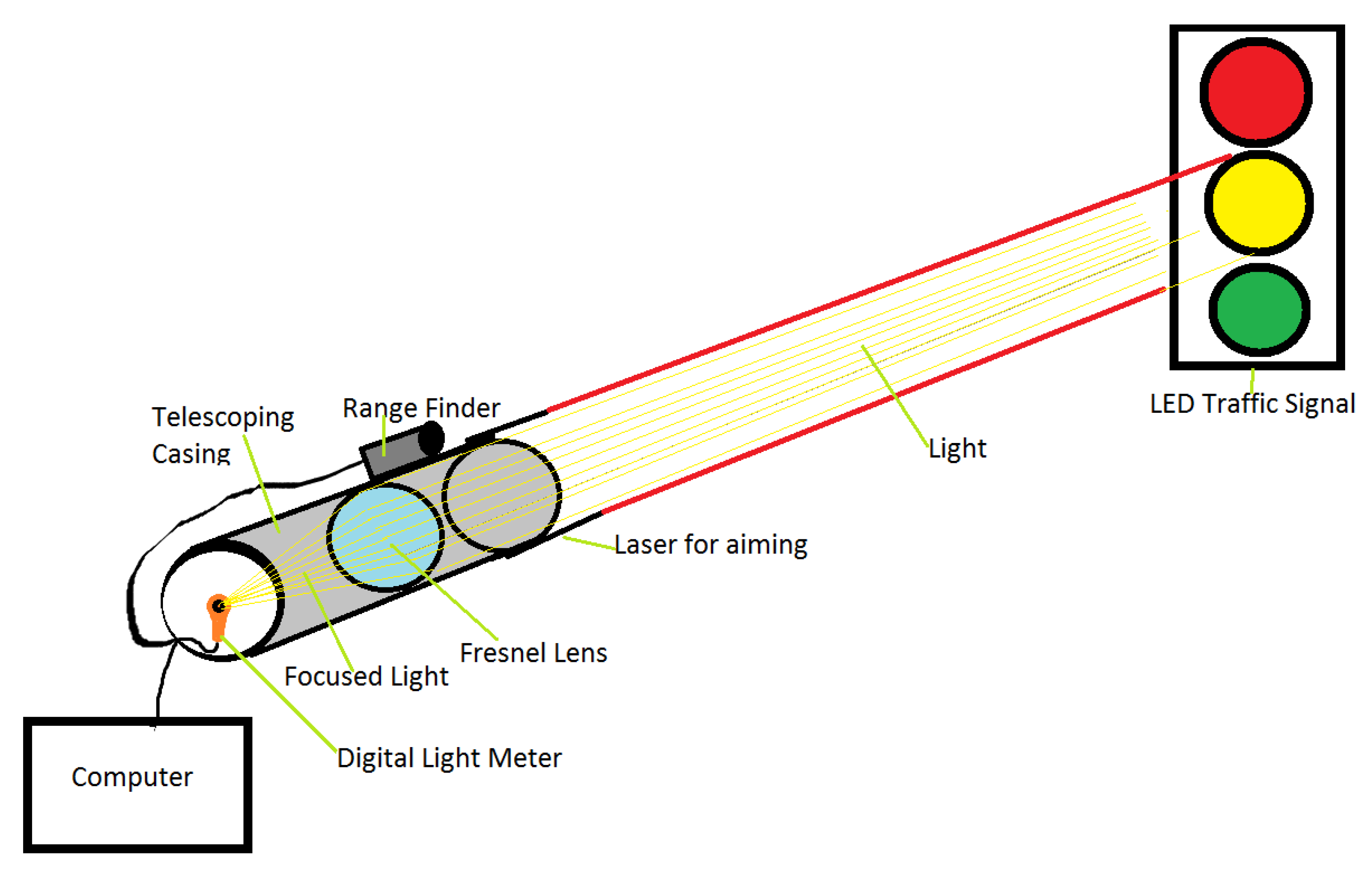
While Arhin’s method required measuring the LED illuminance at the signal itself, Long’s team developed a method for taking readings from the driver’s position in a vehicle. This allowed the team to conduct research without field measurement from a bucket truck or needing to remove a significant number of signals from existing intersections to test them in a lab setting. To collect data the team developed a one-of-a-kind field-testing device to collect illuminance readings from inside of a vehicle. This device (shown in
Figure 1) consisted of a Fresnel lens, concentrating the light reaching the device into a single beam which was then directed towards a light meter, providing a measurement of lux (lumens/m
2). At the same time, a range finder attached to the device measured the distance from the device to the LED module in feet (converted to meters after data collection). Additionally, the team attached a laser pen to the device in order to more accurately aim the device at the modules. The data collector would remain at the intersection to record a full cycle of module illumination. Measurements were recorded automatically into a laptop connected directly to the light meter and the range finder [
14].
Analyzing over 300 collected data points, the research team was able to sort the data based on manufacturer as well as module type. Five manufacturers were identified, although only three were associated with enough data to yield suggestive or significant results by manufacturer (Dialight, GE, and Leotek). Five module types were also sorted (Circular Green, Circular Red, Circular Yellow, Green Arrow, and Yellow Arrow). The majority of the datapoints belonged to Dialight, followed by GE, and noticeably fewer associated with Leotek.
Long et al. determined that LED degradation patterns are related to both manufacturer and module type, as well as the interaction of these two factors. Linear regression models were determined to fit the data appropriately. The replacement ages determined by the Long research can be found in
Table 3.
2.2.5. Schmidt
A report developed for the District Department of Transportation, Traffic Operations, compares two methodologies from previous studies to estimate the lifespan of five-year warrantied LED modules [
15]. These previous studies (Project A and Project B) were both commissioned by the Missouri Department of Transportation (MoDOT) and both were completed by multidisciplinary teams at the Missouri University of Science and Technology. Project A (conducted in 2009) compares the linear regression of operating time in years versus luminous intensity. Project B (conducted in 2012) compares the linear regression of operating time in years versus illuminance. Both projects’ data points were analyzed based on two factors: manufacturer and operating time. See
Table 4 for the lifespan estimates for each project.
The main difference in the data analysis phase of each project was the approach used to determine point estimates across which traffic modules are being compared. Project A collected one point of data per LED module, while Project B collected five points of data per LED traffic module over time (longitudinal) and within manufacturer and signal type (latitudinal). Compared to Project A, the approach for Project B predicts more accurate point estimates and reduces the changes of environmental error.
There are significant differences between the results of the two projects with Project B returning more results.
Each of the studies highlighted in this section utilized a form of regression to determine their recommended replacement age for LED modules. As shown, the expected service life of the modules based on available data was generally found to be longer than the modules’ five-year warrantied life.
2.3. LED Traffic Signal Operations
Part of the literature exploration included searching for documentation of inspection, repair, and replacement (IRR) operating procedures. Numerous examples were found in the literature. They are presented and discussed throughout this section. These operating procedures provide DOTs and other transportation agencies with a plan which will fully utilize their lighting transportation assets. Full utilization of LED modules in the field is the most impactful way to increase their sustainability as an asset, decrease material waste due to inefficient module management, and reduce power consumption.
2.3.1. Inspection Procedures
By and large, the inspection requirements for LED traffic signals are left to individual DOTs. ITE specifications contain requirements for production and testing inspections, however they do not contain guidelines or requirements for the inspection of LED modules after installation.
Due to previously described limitations surrounding the measurement of LED module illuminance (removal of module for lab testing or required equipment to mimic lab environment), tracking this data is not part of a typical inspection. Examples of two traffic signal inspection checklists are provided in
Table 5. The checklist from Virginia is circa 2009 [
16], while the list from Connecticut was more recently published in 2019 [
17]. The two inspection lists, originating a full decade apart, consist of mostly the same inspection items. Both lists do include the LED modules (see Item #3), however no specific data collection for module illuminance tracking is indicated. Given that recent research has not provided any updated degradation models, it does not seem that module illuminance measurement is a regular part of signal inspection. If DOTs were maintaining databases containing illuminance measurements over time, the degradation models for the modules could be validated and updated at regular intervals based on this ongoing data collection process.
2.3.2. Repair and Replacement Procedures
At the start of the transition to LED modules (around 2005) agencies were installing these new LED signal systems with little to no experience or guidance related to their use, maintenance, and lifespan. Few public transportation agencies had maintenance procedures in place for these LED systems, fewer still were tracking the basic data required for proper maintenance [
5,
18]. A lack of national guidelines on LED traffic signal operation and maintenance led those agencies who did develop a maintenance plan to replace modules at anywhere from four to ten years [
5].
Virginia DOT published a paper in 2009 providing clear data points recommended for collection in order to determine proper maintenance procedures for LED Signal Systems [
16]. These parameters were determined as part of a Needs-Based budgeting framework the department utilized to prepare for maintenance expenditures. The list is composed of twenty-two parameters falling in the categories of: Preventative Maintenance, Repair, Replacements, Operating Needs, and Additional Needs. The categories listed are utilized as the various Repair and Replacement Maintenance Phases of the VDOT LED Signal Operating Procedures. Specific timelines for each phase were not provided in the report. However, it was implied that modules were replaced at the five-year mark, while controllers and cabinets were replaced at seven and ten years [
16].
Arhin cites two options available to DOTs for the replacement of LEDs: (1) replace individually as LEDs fall below ITE minimums (spot replacement) or, (2) conduct group replacements (blanket replacement) as some modules fall below minimums (resulting in some modules being replaced before their full lifespan is utilized) [
13]. Long also based their replacement recommendations on LED module degradation. However, their recommendation takes into consideration the fact that an as-needed individual module replacement plan is likely not a viable option, and DOTs should conduct a budget analysis to determine what method of replacement will be the most efficient for themselves [
10].
The development and continued use of a database was recommended throughout the literature. Parameters recommended for a basic LED Module tracking database [
19] include the following.
Parameters recommended for a maintenance database related to LED Signals [
17] add the following.
2.4. Future Directions
Our literature search revealed innovative ideas which have not yet been implemented in the realm of Traffic Signal Systems. These include self-assessing LED modules which contain a dedicated degradation sensor, allowing them to measure and assess their own luminosity and report to a central system [
20]. They also include ‘inside-out’ traffic signal systems, placing the LEDs at the base of the signal pole (accessible from the side of the road) and transmitting the light to the typical module location via fiber optic cables. By using LEDs that are brighter than those required by the International Standard ISO 16508, the cables would be capable of reflecting the light and maintaining the required luminance from the signal [
21]. With regard to data collection, another paper suggested the development of a single camera which would be affixed to the top of an inspection vehicle to record real-time light readings for LED modules. The camera would detect the signal, then record the distance and color as well as the luminosity [
22].
3. Materials and Methods
3.1. Meta-Analysis of Literature
Once substantial sources were identified, the research team conducted a meta-analysis of available literature. This analysis examines publication timelines as well as major content themes. Results of this analysis can be found in
Section 4.1.
3.2. Manufacturer Warranties and Failure Rates
In conjunction with the literature review process, the research team was able to conduct informational interviews with two of the leading LED manufacturers. Findings from these interviews can be found in
Section 4.2.
3.3. Current Practices
To determine current IRR practices, the research team reached out to active transportation agencies for their feedback. As this study took place during the global COVID-19 pandemic, the majority of interviews with agency personnel were conducted virtually using a digital meeting software. Information interviews were conducted with agency personnel from the state office as well as subdivision offices. To conduct comparable interviews, the research team developed a baseline questionnaire. A report produced by the Virginia Department of Transportation (VDOT) was identified during the literature review as being extremely well organized in the area of explaining current practices [
16]. The following subject matter from that work was used to organize the interview questions.
Testing, Deterioration, and Standards
Framework for Signal O&M Needs Assessment
A total of fifty-one questions were developed by the research team for use during interviews. As shown above, these questions cover a wide variety of topics and were used as a starting point to guide the interview discussions. Agency personnel were interviewed at a variety of levels; thus, the question list was tailored to create a dynamic discussion specific to the position of the interviewee.
Answers to the interview questions were then compiled and analyzed to determine a standard IRR procedure for the agency. Once this procedure was identified, it was sent back to agency personnel for verification of accuracy. The results of this case study can be found in
Section 4.3.
4. Findings
This section is divided by subheadings as listed above. It should provide a concise and precise description of the qualitative results and their interpretation.
4.1. Meta-Analysis of Literature
4.1.1. Analysis of Publication Timeline
This section details the literature that was found in terms of timeline and research relevancy.
Figure 2 shows a distribution of all forty of the sources identified organized by year published. In any given year we were able to find a maximum of four published sources related to the topic of traffic signal IRR.
Figure 3 shows all forty sources identified distributed by their relevance to the project. Each source was assigned a relevancy score by the research team based on the type, quality, and specificity of content contained. By relevancy we mean the extent to which a paper addressed traffic signal LED inspection, replacement, and lifespan. The research team identified twenty-two of the forty sources to have a relevancy score of eight or higher out of ten. The project team decided that a score of eight or more draws attention to the documents that provide the greatest benefit to the project. Eighteen of the forty documents fell below this threshold (dashed line in
Figure 3).
Table 6 provides a matrix demonstrating the relevance of literature published over time. Highlighted portions of the table show that there was a peak in relevant literature between 2009 and 2012. This aligns with an industry response to the supplements released by ITE in 2005 and 2007. The peak in 2016 is the result of less relevant literature. The lack of recent, relevant literature on this topic has been a surprise, especially given the critical use of traffic signals.
4.1.2. Analysis of Publication Content
During the process of reviewing the literature, the research team developed a list of key topics.
Table 7 provides this list of key topics and their definitions. These topics were used in the classification and sorting of literature. Note that different users apply different names to the portion of the signal which houses the LED. This paper uses the term module, other common terms include indicator and signal. Also note that the term signal is frequently used as a blanket term for many signal-system related items: intersections, signal heads, LEDs, individual light poles supporting signal heads, etc. The top five topics present in the available literature are:
Maintenance (covered in 21 publications)
LED Degradation (covered in 17 publications)
Record Keeping (covered in 16 publications)
Safety (covered in 14 publications)
Inspections (covered in 12 publications)
4.2. Manufacturer Warranties and Failure Rates
As part of the research process, the team was able to meet with two leading LED manufacturers, Leotek and Dialight. Meeting with Leotek reinforced information previously acquired during the literature review. The latest LED module specifications are the ITE Signal Specifications from 2005 and 2007. However, there have been LED technology improvements since then which allow the module warranty to be extended. The LED module market has recently shifted to providing modules with a fifteen-year warranty. This is triple the warranty of all of the modules utilized in previous research and is a significant upgrade in LED module quality and performance. Ultimately, the decision to warrant the modules for fifteen years is the result of a combination of business risk evaluation and technological improvements. Dialight reiterated this development, indicating specifically that improvements have been made in the power supply and the wiring of the modules to increase the lifespan. Dialight mentioned in-house testing of the modules as the foundation of their new fifteen-year lifespan. However, because these are new products they have not been use long enough to enable the collection of in place field data.
Though neither manufacturer provided the research team with the raw data they utilized in determining these lifespan estimates, each was willing to share summary information with the research team. Through accelerated testing methods, module manufacturers were able to determine that failure among LED modules follows a Bathtub Curve.
Figure 4 shows an example of this kind of expected failure profile. The observed failure rate shown at the top is a compilation of the various failure rates found to exist within a body of LED modules. Users should expect that early on there will be a higher rate of failure as those modules which may have subpar wiring or other components will fail quickly. This can be referred to as “Infant Mortality” Failure. Towards the end of the expected life an increasing quantity of modules will fail. These modules have been in place for some time and such failures experience can be called “Wear Out” failures. It was also found that there is a constant level of random failures throughout a sample of LED modules. Combining these three failure types into one Observed Failure Rate results in the bathtub shaped curve seen at the top of the figure.
Understanding this failure curve is important for transportation planners. The failure rates provided here can be considered when transportation agencies are allocating man hours and determining their budget for IRR processes involving LED modules. Accounting for a reasonable number of spot replacements (which is what these failure rates show) ensures that agencies will stock enough LED modules to get them from one blanket replacement series to the next.
Analysis of data found on publicly available warranty documentation confirms that the 15-year-warrantied modules have a similar wattage as the 5-year-warrantied modules. This means that a jump in energy use is not expected with the transition to the upgraded product. The 5-year-warrantied modules run on between 3.6 and 21 watts, while the 15-year-warrantied modules require anywhere from 6.2 to 14 watts. Simply continuing to use LEDs will ensure that DOTs see continued reduction in energy use from the previous standard of incandescent lights (typically at 100 watts per module).
4.3. Current Practices
Transportation agency employees reported that LED modules were being replaced at the five-year mark. A five-year service life is in line with the five-year warranty period of the modules currently used by the agency, although a transition to fifteen-year warrantied modules is underway. The initial process of transitioning from incandescent to LED modules occurred during the late 2000s and early 2010s. One division within the agency was able to provide detailed mapping and data outlining the blanket replacement process undertaken during this transition. Based on conversation with the remaining divisions, there is an indication that each division across the state utilized a similar blanket replacement process to make the initial switch. The blanket replacement plan typically spanned five years. During each year, approximately 20% of the intersections within a division converted their incandescent bulbs to LED modules. The plan initially was to continue this blanket replacement process as a cycle, ensuring that all modules across the state were replaced at the five-year mark. However, budget cuts, personnel shortages, and more recently, the COVID-19 pandemic as barriers to the continuation of a blanket replacement cycle.
Due to these barriers, many of the divisions in the agency are working on a spot-replacement heavy repair and replacement procedure. In some areas there are plans to replace the modules at around 30 intersections in the upcoming year this represents only 6% of the existing intersections in the division and is a significant drop from the previously planned 20%. This lowered rate of replacement implies that LED modules are remaining in the field past their warranty-specified lifespan. Due to the warrantied lifespan being the time of expected failure, it also implies that ‘failed’ LED modules are remaining in the field. Remember that the moment of failure in this context is the moment at which the LED module has degraded below the ITE minimum standard of luminosity. A failed LED module will still function. However, dim LED modules pose a safety hazard to drivers and others on the roadways.
Based on interview responses, the research team was able to develop a process diagram to represent current LED Operating Procedures.
Figure 5 contains a process diagram outlining these procedures. This diagram is based on the assumption that sufficient LED modules are in the field and technicians are only dealing with spot repairs and replacement. After initial signal installation, each intersection undergoes regular inspections. For participating agencies this means that two six-month inspections are performed each year. Along with the six-month inspections are an annual inspection and a two-year inspection. Each of these inspection checklists builds on the others, meaning that the annual inspection covers more than the six-month and the two-year covers more than the annual.
If an inspection fails, the type of failure will determine the repair or replacement actions required to fix the signal system at that intersection. If the failure is uncomplicated and not urgent, the repair will be scheduled within one to two days. If the cause of the failure was significant and not urgent, then additional planning will be needed to rectify the issue, but the repair will be scheduled within two to three weeks. If the cause of the failure is urgent the next question is whether a lane shutdown is required. If a lane shutdown is required, then emergency maintenance must be scheduled with an outside contractor. If no lane shutdown is required, then the technicians will work alone or in pairs based on whether or not a bucket truck is required.
Additional triggers for repair and replacement activities include calls from local police or citizen informing the agency of an LED that is inoperable or that has switched to flashing. The signal systems are typically set up such that if an LED does go out, the intersection will switch to flashing rather than continue the typical phased light series. If an intersection is flashing, the system will alert the local office. It is also possible that someone in the community will notice the change in the intersection and call the office before the agency is otherwise made aware of the outage.
Because of the emergence of longer lifespan LEDs, transportation agencies are currently in the process of transitioning from five-year warrantied modules to fifteen-year warrantied modules. With this being the case, guidance on the optimum IRR, including both blanket and spot replacements will be key in maintaining a safe and sustainable LED module management program.
5. Conclusions
The literature examined here was able to answer our research questions. “Does previous research provide information regarding the service-life of LED modules?” Yes. Previous research has shown that the service-life of LED modules is often estimated to exceed the warranty period of the product. It should be noted that the LED modules included in these studies were warrantied for five years by the manufacturers. The range of estimated lifespans (3.5 to 14 years) indicates that transportation agencies may be able to plan for a service life that exceeds the warranty period. That the three papers which provide specific lifespan estimates are all from 2014 or earlier is an indication that the topic of LED degradation and replacement cycle planning should be revisited given the recent advances in technology. Knowledge gaps have been identified. The emergence of 15-year-warrantied LED modules, combined with the lack of an established guideline for their introduction into practical use, shows that additional work is appropriate to ensure continued sustainable use of these products.
“What strategies does recent research provide for determining inspection, repair, and replacement procedures?” Examining available literature shows that there are few identified strategies for the IRR process related to LED modules. The same studies determining service life of modules have suggested replacement timelines. Other sources have published their internal inspection checklists. However, no single best practice has been identified for LED module IRR. Literature indicates a clear need for an accurate module database. This would be an operational database that enables DOTs to fully document their inventory, determine its conditions, and evaluate its performance. That will be an ongoing process that is only recently beginning because no data is yet available for 15-year warrantied modules. Such studies are critically necessary.
Manufacturers were able to answer, “What do recent technological advancements mean for the expected service life of LED modules?” Technological developments have increased the expected life of LED modules to the point that major manufacturers are tripling their product warranties. Manufacturers also provided additional insight into the rates of failure that a transportation agency should expect throughout their LED operations cycles. A technical evaluation of the new LED products ensures that the established reduced rates of energy use will be maintained throughout a system upgrade.
From the participating agency we learned about “policies which are currently in place regarding IRR”. Due to the structure of the agency in the case study, it was found that each division was responsible for their own LED module IRR. However, it was also found that the divisions surveyed followed similar processes. This is without explicitly documented policies in place. Finally, “What are current IRR practices?” The participating transportation agencies have identified a three-tier inspection process which enables them to systematically identify any issues at their intersections. Inspections, combined with notice from agency personnel and local citizens, ensure that repairs are taking place as needed within a division. The Replacement processes are where additional guidance is required. Citing budget and personnel shortages as reasons for discontinuing the regular blanket replacement process could be avoided. Establishing a strategy of blanket replacement which will enable transportation agencies to systematically replace LED modules as soon as they reach failure will ensure that dim modules do not remain in the field, increasing driver safety. It is likely that this will also decrease the quantity of spot replacements required in a region due to the increased Late Failure rate, freeing agency resources for other work.
There is also the possibility that the resource needs of the Traffic Signal Systems departments are being misunderstood due to a lack of guidelines around LED module IRR, leading to insufficient budget and personnel placement. Barriers related to unanticipated future events cannot fully be addressed by a guideline, as such events cause extreme changes in the price and shipping times of various materials.
A final conclusion is that new LEDs, with their tripled lifespan, if utilized effectively, will yield cost and material reductions for transportation agencies. They will also provide agencies with the infrastructure longevity needed to ensure that the repair and replacement strategy implemented is possible with current personnel. Improvements in the utilization of this transportation infrastructure asset will have a large impact on the overall sustainability of the system. Benefits will multiply, simply due to the volume with which we utilize traffic modules.
6. Recommendations
As previously discussed, there is currently no simple method for measuring the luminosity of LED modules in the field on a regular basis. This, combined with LED failure being slow degradation rather than a catastrophic event also means that there are likely LED modules in place which have dropped below acceptable ITE standards, but appear sufficiently luminous to some observers. Development of an IRR guideline for LED modules which will be critical in optimizing the sustainable benefits of utilizing LEDs, maintaining a high level of safety for those on the roads, and reducing energy consumption.
Authors planned work includes development of repair and replacement strategy alternatives to be evaluated via microsimulations. This planned work will assess timelines for upgrading of the LED Module aspect of transportation infrastructure as well as overall impacts on energy and material use, and cost and budget implications for transportation agencies. Microsimulations have been utilized previously for assessment of energy usage and are an appropriate next step for this research [
23].
Author Contributions
Conceptualization, W.R.; methodology, W.R.; software, M.W.; validation, M.W. and W.R.; formal analysis, M.W.; investigation, M.W. and W.R.; resources, M.W.; data curation, M.W.; writing—original draft preparation, M.W.; writing—review and editing, M.W. and W.R.; visualization, M.W. and W.R.; supervision, W.R.; project administration, M.W. and W.R.; funding acquisition, W.R. All authors have read and agreed to the published version of the manuscript.
Funding
This research was funded by the North Carolina Department of Transportation, grant number RP 2021-13 titled “Traffic Signal Replacement Assessment”.
Institutional Review Board Statement
Not applicable.
Informed Consent Statement
Informed consent was obtained from all personnel who were interviewed for this study. Written consent was obtained from NCDOT to publish this paper.
Data Availability Statement
Data used in this paper can be obtained from the authors.
Acknowledgments
The opinions, findings, conclusions, or recommendations presented in this paper are those of the authors and do not reflect the views of NCDOT or any other individuals.
Conflicts of Interest
The authors declare no conflict of interest.
References
- Urbano, E.M.; Martinez-Viol, V.; Kampouropoulos, K.; Romeral, L. Energy-Investment Decision-Making for Industry: Quantitative and Qualitative Risks Integrated Analysis. Sustainability 2021, 13, 6977. [Google Scholar] [CrossRef]
- Better Lighting Coming for Interstates and Major Highways Across North Carolina, North Carolina Department of Transportation. 2017. Available online: https://www.ncdot.gov/news/press-releases/Pages/2017/Better-Lighting-Coming-for-Interstates-a.aspx (accessed on 1 December 2022).
- Montella, A.; Chiaradonna, S.; Mihiel, A.C.d.s.; Lovegrove, G.; Nunziante, P.; Rella Riccardi, M. Sustainable Complete Streets Design Criteria and Case Study in Naples, Italy. Sustainability 2022, 14, 13142. [Google Scholar] [CrossRef]
- Rella Riccardi, M.; Galante, F.; Scarano, A.; Montella, A. Econometric and Machine Learning Methods to Identify Pedestrian Crash Patterns. Sustainability 2022, 14, 15471. [Google Scholar] [CrossRef]
- Behura, N. A Survey of Maintenance Practices of Light-Emitting Diode Traffic Signals and Some Recommended Guidelines. ITE J. 2007, 77, 18–22. [Google Scholar]
- Gaha, M.; Chabane, B.; Komljenovic, D.; Côté, A.; Hébert, C.; Blancke, O.; Delavari, A.; Abdul-Nour, G. Global Methodology for Electrical Utilities Maintenance Assessment Based on Risk-Informed Decision Making. Sustainability 2021, 13, 9091. [Google Scholar] [CrossRef]
- Vehicle Traffic Control Signal Heads Light Emitting Diode (LED) Circular Signal Supplement. Joing Industry and traffic Engineering Council Committee, Institute of Traffic Engineers: Washington, DC, USA, 2005. Available online: https://connect.ncdot.gov/resources/Materials/MaterialsResources/LED%20Signals%20Presentation.pdf (accessed on 1 December 2022).
- LED Committee of the Traffic Engineering Council. Vehicle Traffic Control Signal Heads-Light Emitting Diode (LED) Vehicle Arrow Traffic Signal Supplement; Washington, DC, USA, 2007. [Google Scholar]
- Behura, N. The New ITE Light-Emitting Diode Traffic Signal Specifications—A Guide for Purchasers. ITE J. 2005, 75, 38–40. [Google Scholar]
- Long, S.; Gosavi, A.; Qin, R.; Noll, C. Evaluating Useful Life and Developing Replacement Schedules for LED Traffic Signals: Statistical Methodology and a Field Study. Eng. Manag. J. 2012, 24, 15–23. [Google Scholar] [CrossRef]
- Chang, M.H.; Das, D.; Varde, P.V.; Pecht, M. Light Emitting Diodes Reliability Review. Microelectron. Reliab. 2012, 52, 762–782. [Google Scholar] [CrossRef]
- Singh, P.; Tan, C.M. Degradation Physics of High Power LEDs in Outdoor Environment and the Role of Phosphor in the Degradation Process. Sci. Rep. 2016, 6, 24052. [Google Scholar] [CrossRef] [PubMed] [Green Version]
- Arhin, S.; Bellamy, T.; Cheeks, J.; Harvey, A. Evaluation of Life Expectancy of LED Traffic Signals and Development of a Replacement Schedule in the District of Colombia; Washington, DC, USA, 2011. [Google Scholar]
- Long, S.; Qin, R.; Gosavi, A.; Wu, C.H.; Ryan, T.; Noll, C. Life Expectancy Evaluation and Development of a Replacement Schedule for LED Traffic Signals; University of Missouri: Rolla, MO, USA, 2011. [Google Scholar]
- Schmidt, S.; Kothapalli, V.S.; Long, S.; Qin, R. Comparison of Statistical Analysis Methodologies for LED Indication Replacement Schedules. In Proceedings of the Industrial and Systems Engineering Research Conference, Palais des Congrés de Montréal, MTL, Montréal, QC, Canada, 31 May–3 June 2014. [Google Scholar]
- Chen, W.; Henley, L.; Price, J. Assessment of Traffic Signal Maintenance and Operations Needs at Virginia Department of Transportation. Transp. Res. Rec. J. Transp. Res. Board 2009, 2128, 11–19. [Google Scholar] [CrossRef]
- Preventative Maintenance of Traffic Signals. Technical. Brief. 2019. Available online: file:///C:/Users/William%20Rasdorf/Documents/Preventative-Maintenance-of-Traffic-Signals%20(1).pdf (accessed on 1 December 2022).
- Urbanik, T. LED Traffic Signal Monitoring, Maintenance, and Replacement Issues; National Academies Press: Washington, DC, USA, 2008; ISBN 978-0-309-27970-3. [Google Scholar]
- Long, S.; Qin, R.; Gosavi, A.; Wu, C.H.; Ryan, T.; Noll, C. LED Traffic Signal Replacement Schedules: Facilitating Smooth Freight Flows; University of Nebraska: Lincoln, NE, USA, 2012. [Google Scholar]
- Elwany, A.H.; Gebraeel, N.Z.; Maillart, L.M. Structured Replacement Policies for Components with Complex Degradation Processes and Dedicated Sensors. Oper. Res. 2011, 59, 684–695. [Google Scholar] [CrossRef]
- Pérez-Ocón, F.; Rubiño, M.; Pozo, A.M.; Rabaza, O. Design of New Traffic Lights: Traffic Safety and Maintenance Ease. Eng. Struct. 2013, 57, 388–392. [Google Scholar] [CrossRef]
- Diaz-Cabrera, M.; Cerri, P.; Medici, P. Robust Real-Time Traffic Light Detection and Distance Estimation Using a Single Camera. Expert. Syst. Appl. 2015, 42, 3911–3923. [Google Scholar] [CrossRef]
- Hasan, U.; Whyte, A.; AlJassmi, H. A Microsimulation Modelling Approach to Quantify Environmental Footprint of Autonomous Buses. Sustainability 2022, 14, 15657. [Google Scholar] [CrossRef]
| Disclaimer/Publisher’s Note: The statements, opinions and data contained in all publications are solely those of the individual author(s) and contributor(s) and not of MDPI and/or the editor(s). MDPI and/or the editor(s) disclaim responsibility for any injury to people or property resulting from any ideas, methods, instructions or products referred to in the content. |
© 2023 by the authors. Licensee MDPI, Basel, Switzerland. This article is an open access article distributed under the terms and conditions of the Creative Commons Attribution (CC BY) license (https://creativecommons.org/licenses/by/4.0/).


