Abstract
Vehicle force identification is one of the core technical problems to be solved urgently in the management of transportation infrastructure, and it has also been a research hotspot in recent years. To promote the application of vehicle force identification technology on bridges and explore its development direction, the development status of indirect vehicle force identification methods based on bridge response is reviewed during this study. The basic theories of two major methods, including bridge weigh-in-motion (BWIM) and moving force identification (MFI), are described in detail in this study, and then, the key technical principles of bridge force identification are revealed. Secondly, the development status of BWIM in recent years is reviewed from three aspects, including test accuracy, applicability and test efficiency. Combined with a variety of theories, the current status of MFI is analyzed from the establishment of the solution to the equation. Finally, the development direction of an artificial neural network and machine vision technology are prospected in this study. The BP neural network has good self-learning ability and self-adaptive ability, but the algorithm needs to be improved. The identification method based on machine vision represents the current development direction in vehicle force identification, with great potential.
1. Introduction
Bridges are key projects in national transportation infrastructure and play an irreplaceable role in ensuring the normal operation of the road network. By the end of 2022, the number of road bridges in China had reached 1,033,200, with an extension of 85,776,490 m [1]. At the same time, the national traffic flow and force capacity also increased sharply, which brought a lot of inconvenience to the existing bridge management, as well as a greater security risk. In recent years, the fatigue deterioration and damage degree of bridges caused by vehicle overload have accelerated rapidly, seriously affecting the bearing capacity and service life of bridges. In addition, bridge collapse accidents caused by the above factors have also occurred frequently [2,3]. Therefore, it is very important to improve bridge traffic control and accurately evaluate bridge-bearing capacity and remaining life. The monitoring of vehicle weight and the study of load effect are the key parts.
The monitoring of vehicle weight is an important part of bridge traffic control. However, traditional static weighing takes a lot of time, which seriously affects the transportation efficiency. The road dynamic weighing system can only obtain a short dynamic response by embedding sensors in the road pavement, which has poor durability and limited accuracy. In response to these problems, Moses [4] proposed the concept and basic theory of bridge weigh-in-motion (BWIM), based on the static influence line method in 1979, and estimated the speed, weight and axle information on the vehicle through the vibration response of the bridge itself under vehicle force. This method has the advantages of high efficiency, low cost and strong durability and can obtain sufficient response data to ensure the test accuracy. Therefore, since the method was proposed, the related scholars have carried out extensive research and achieved a series of innovative results. For example, Ojio et al. [5,6] proposed the influence line area method and the bearing reaction method from different angles, and Deng et al. [7] proposed the virtual simply-supported beam method to identify the vehicle force of long-span bridges.
The static force is identified based on the BWIM method, while the dynamic force identification, as an important inverse problem in dynamics, is an effective means to explore vehicle–bridge interactions, which are of great significance for future bridge design, operation and maintenance. In order to identify vehicle dynamic force, O’Connor et al. [8] proposed the first interpretive method I (IMI) for moving force identification (MFI) in 1988. Based on the above, Law and Chan et al. [9,10,11,12] successively proposed the time domain method (TDM), the frequency–time domain method (FTDM) and the interpretive method II (IMII). These methods analyzed the core idea of MFI from the dynamic principles, confirming the authenticity and effectiveness of MFI and laying a foundation for subsequent research by scholars.
With the rapid development of computer technology in the fields of civil engineering and transportation, artificial neural networks, machine vision and other technologies are gradually introduced into bridge force recognition. As a type of artificial neural network, BP neural networks have been widely used in the field of bridge force recognition in recent years. Compared with the BWIM and MFI methods, BP neural network technology [13] does not need to establish complex mechanical and mathematical models, which effectively reduces the difficulty of calculation and modeling. With the development of artificial intelligence, machine vision and deep learning technologies [14] have advantages such as intelligence, low cost and non-contact, as well as being more comprehensive in identifying vehicle information, which is a promising development direction at present.
The evolution of the bridge force identification method is shown in Figure 1.
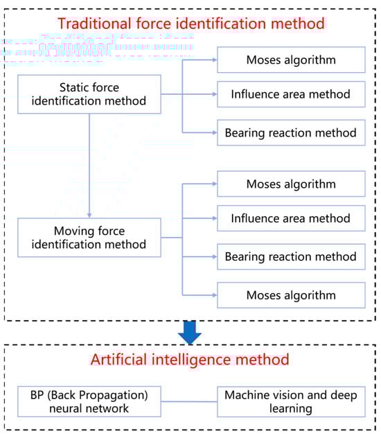
Figure 1.
Evolution diagram of the bridge force identification method.
In order to systematically review the research progress of bridge load recognition methods, the basic theories and research progress of BWIM and MFI methods for static load recognition and dynamic load recognition are mainly described in this study. Additionally, the development direction of artificial neural network and machine vision technology is prospected, aiming to provide a reference for future research direction on bridge load recognition.
2. Traditional Force Identification Method
2.1. Static Force Identification Method
As an important means to obtain vehicle static force, bridge dynamic weighing is widely used in bridge health monitoring, traffic control and other fields. In this method, the bridge is used as a weighing scale to calculate the weight of the vehicle passing on it. The BWIM system flow chart is shown in Figure 2. When the vehicle passes the bridge, the dynamic response of the relevant section of the bridge is measured, the collected data are processed, and the output is calculated to obtain the vehicle’s weight, speed, wheelbase and other parameters. At present, the BWIM system is mostly composed of the following parts: (1) strain sensor, including a weighing sensor and axle detection sensor. The force cell is installed at the bottom of each beam to measure the dynamic response of the bridge. The axle detection sensor, also known as the FAD (Free of Axle Detector) sensor, is installed under the bridge panel to obtain the FAD signal. (2) Data acquisition system; (3) BWIM algorithm and output: the distance between FAD sensors and the time difference of peak response are used to obtain the information of speed and wheelbase; axle information and the BWIM algorithm are used to obtain axle force information.
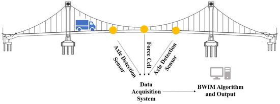
Figure 2.
BWIM system flow chart.
The following sections will briefly describe the basic theory of BWIM and discuss the development status of BWIM in detail.
2.1.1. Basic Theory
In order to obtain the accurate static force of a vehicle, relevant scholars have put forward various algorithm theories based on the influence line method. Among them, the BWIM classical algorithms mainly include the Moses algorithm, the influence area method and the support reaction method.
- (1)
- Moses algorithm
Moses [4] proposed the concept of dynamic weighing of simply supported beam bridges in 1979. If the total bending moment of a section of a bridge is , at time step can be expressed as,
where is the elastic modulus, is the section modulus (assuming the of each beam is the same), is the theoretical strain of the beam at the time step , is the sum of k theoretical strain at the time step , and is the total number of beams.
When the vehicle is driving across the bridge at time step , the section bending moment generated by the vehicle force can be expressed as,
where is the number of axles, is the axle weight of the axle, is the ordinate of the bending moment influence line at the position of the axle at time step , is the frequency of the strain sampling system, is speed, is the distance between the axle and the first axle, is the number of collection points corresponding to .
According to Equations (1) and (2), at time step , the corresponding theoretical strain is,
The error function of theoretical strain and measured strain is defined as,
where is the total number of sampling points, is the sum of measured strains of all beams at time step . In order to minimize the error function , based on the least square method, the following equation can be obtained,
According to Equation (6), sets of equations can be obtained, and can be obtained by combining the equations.
- (2)
- Influence area method
In 2002, Ojio et al. [5] proposed the influence line area method, which expressed the response curve area as the product of the total vehicle weight and the influence line area. The expression can be expressed as,
where is the area under the response curve, is the number of axles, is the axle weight of axis , is the influence line function, is the position of the first axle, is the distance from axle to 1 axle, and (Gross Vehicle Weight) is the total axle weight of the vehicle.
When the total axle weight of the calibrated car is known, the total axle weight of other vehicles can be calculated based on Equation (7), which can be expressed as,
where and are the total axle weight and response area of the calibrated vehicle, respectively. This method is easy to operate but can only measure the total axle weight of the vehicle and cannot identify the single axle weight.
- (3)
- Bearing reaction method
The bearing reaction influence line method proposed by Ojio et al. [6] in 2005 is also one of the classical algorithms of BWIM. This method considers that when the force appears on the bridge for the first time, it is exactly the maximum influence line of the support reaction, so the axle force can be calculated from the peak value of the wave.
The Moses algorithm, the influence area method and the support reaction method, as the classical algorithms of BWIM, are of great significance to the development of the BWIM system. The advantages and disadvantages of these three classical algorithms are illustrated in Table 1. In order to make the BWIM system widely used in practice, subsequent scholars improved the test accuracy and efficiency on the basis of these methods and further evaluated and expanded the application scope of BWIM.

Table 1.
Comparison and summary of static force identification methods.
2.1.2. Test Accuracy
Due to the interference of many uncertain factors, such as road roughness, vehicle speed and environmental noise, the test accuracy of BWIM is easily affected by the influence of line calibration, axle information and equation suitability. In the Moses algorithm, the theoretical influence line did not consider the dynamic effect. In order to obtain accurate information on the influence line, O’Brien et al. [15] tested vehicles with known axle force, obtained their dynamic response, and calibrated the ordinate of the influence line with the least square method. Ieng et al. [16] pointed out that the method is susceptible to noise interference and modified the method by using the principle of maximum likelihood estimation. The modified method used more signals, thus reducing the impact of noise generated by specific signals. In order to reduce the disturbance of uncertainty factors, Yoshida [17] proposed Bayesian Bridge Weigh-in-motion (BBWIM) for the data assimilation into the model and to establish a coherent Bayesian framework. The results show that the uncertainty of axle force can be reduced when closely spaced shafts have similar weights. Zhang et al. [18] used the influence area method to distinguish the strain generated by temperature from the total strain, which could more accurately obtain the complete waveform of the vehicle passing on the bridge, thus improving the accuracy of the bridge dynamic weighing. As for the problem of equation fitness, the solution to the equation is usually ill-conditioned, especially for vehicles with rough road surfaces and close axle spacing. In this regard, Zhang et al. [19] proposed a BWIM iterative algorithm. Based on the Moses algorithm, the measured influence lines were continuously iterated until converging, which corrected the ill condition that the accuracy of the equation would be low under special circumstances and obtained more accurate axle load results. Wang et al. [20] used the Moses algorithm to identify each axle force of the vehicle and adopted a gradient method for local optimization of the initially identified axle force, further improving the recognition accuracy. Axle information is an important factor affecting the accuracy of BWIM, which has a high requirement on noise level. Zhu et al. [21] conducted tests based on the bearing reaction method, and the results showed that the method was not affected by noise and road roughness and could accurately identify axle information and vehicle weight. Considering axle signals that are difficult to identify directly, Zhao et al. [22] selected the optimal transform scale and the optimal transform wavelet function by jointly controlling the minimum Shannon entropy and the maximum correlation coefficient and then carried out the wavelet transform. The results showed that wavelet transform could improve the efficiency and accuracy of axle information recognition.
2.1.3. Test Efficiency
In terms of the test efficiency of BWIM, the traditional strain sensor arrangement is cumbersome and has poor durability. To solve this problem, He et al. [23] proposed a new virtual axle method, which uses a pre-calibrated bridge influence line, response and speed in the identification process. The results show that this method can obtain a better recognition effect without using additional equipment such as axle detection sensors. Deng et al. [24] proposed the equivalent shear method, which can directly obtain axle information from the strain at the bottom of the bridge, avoid complex signal processing, overcome the shortcomings of traditional axle detection sensors, and improve the measurement accuracy. Since steel bridges consume a lot of time when installing sensors, Sekiya et al. [25] proposed a portable BWIM system that uses only small accelerometers to effectively improve test efficiency. Based on this, Mustafa et al. [26] proposed an iterative linear optimization method, and the results showed that the system could identify axle force density with higher accuracy. In terms of improving computational efficiency, Qian et al. [27] proposed a method to identify force by using the bending moment influence line based on the modal superposition theory. This method utilizes both bending moment response data and acceleration data to avoid solving dynamic equations. Wang et al. [28] used dynamic strain response to fit the influence line to identify the axle force, and the results showed that the method required fewer system parameters and was more feasible than the traditional method.
2.1.4. Applicability Study
At present, scholars have carried out a lot of research on test accuracy and efficiency, but most of them are limited to the condition of small and medium-sized span, thin bearing components and few vehicles. The following contents will be discussed from two aspects, including bridge type and multi-vehicle working conditions.
- (1)
- Bridge types
In order to assess the applicable scope of bridge types, Wang et al. [29] analyzed the application degree of BWIM in various types of bridges, discussed how to evaluate its accuracy grade and discussed the current level of test accuracy. Deng et al. [30] studied the applicability and identification accuracy of the BWIM system for the medium and small-span concrete beam bridges, which are used most widely in China. Then, the influence of different types of cross sections, bridge span, vehicle information, road roughness and test points on BWIM is analyzed. Aiming at the problem that the accuracy of BWIM decreases with the increase in span, Deng et al. [7] put forward the concept of the virtual simply supported beam method to identify vehicle weight by selecting the section of the bridge. The results show that this method is not limited by the span, and the span scope of BWIM is extended effectively. In order to expand the scope of application of bridge type, Zhao et al. [31] conducted experimental research on a continuous rigid frame box girder bridge based on the new BWIM system of fast Fourier transform, which can effectively identify the speed and axle weight of vehicles passing over the bridge. Zhang [32] used the BWIM system to analyze the overall effect of orthotropic steel box beams, and the research showed that the local effect at the fulcrum was more significant, and the identification of axle load at the quarter point and the fulcrum has a higher accuracy. He et al. [33] proposed a force identification method for three-span continuous beam bridges based on the influence area method, which can accurately identify the speed and total weight under a single force.
- (2)
- Multi-vehicle condition
At present, the applicability of BWIM in multi-vehicle conditions needs to be improved. Ren et al. [34] summarized the development of the BWIM system, highlighted the main problems and applicability, and then classified and discussed the multi-vehicle operating conditions. Faced with the situation of a lateral multi-vehicle, Dong [35] used independent components to separate the bridge strain signal and compared several separation algorithms. The results showed that the second-order blind identification algorithm with weight adjustment had a better separation effect. Gong et al. [36] used the Moses algorithm to distinguish vehicle response variables by the lateral dynamic response line to identify multi-vehicle working conditions. The results showed that the accuracy could meet certain requirements, but the increase in the number of vehicles would reduce the recognition accuracy. Chen et al. [37] proposed a BWIM method considering multi-vehicle grating based only on a long-specification fiber Bragg grating (FBG) sensor, then the results showed that the method could accurately identify vehicle speed, wheelbase and axle force. However, further numerical research and field tests were needed for grating on actual bridges. In addition, for the multi-girder structure, Zuo et al. [38] used the force lateral distribution coefficient to distribute the vehicle force to each main beam, transferred the one-dimensional force situation to the two-dimensional one, and used the blind source separation theory to effectively identify the multi-vehicle working conditions.
2.2. Moving Force Identification Method
Compared with the BWIM method, MFI can obtain vehicle force time history information, which can better study vehicle–bridge interactions and has a certain value in fatigue and damage research. Meanwhile, MFI has important reference significance for bridge-bearing capacity assessment and remaining-life prediction. The following contents will briefly describe the four basic theories, including IMI, IMII, FTDM and TDM, and then discuss the current research status of MFI.
2.2.1. Basic Theory
Moving force recognition refers to the recognition of vehicle load duration force. When the dynamic response of the structure and the characteristic matrix of the system are known, the moving force can be obtained by solving the following linear equations,
where is the system characteristic matrix, is the unknown moving force vector, and is the actual dynamic response vector.
- (1)
- First Interpretation Method (IMI)
In order to obtain the time-history curve of vehicle force, O’Connor and Chan [8] proposed IMI in 1988. The method is a discrete element method that reduces simply supported beams to a series of massless elastic beams connected by massless ones. The following equation gives the nodal response of displacement and bending moment at any time,
where is the mass matrix in diagonal form, is the axial force vector, is the damping matrix, is node displacement due to force, is the node bending moment matrix caused by force, is the node displacement caused by the internal force of the node, is the node bending moment matrix caused by the internal force of the node, is the bending moment of the node, is the node displacement, is the node speed, and is the acceleration vectors. If or are known, then and can be obtained by numerical differentiation, and can be solved by the Equations (10) and (11) using least square method.
- (2)
- Second Interpretation Method (IMII)
In 1999, Chan et al. [11] proposed IMII, which regarded the bridge model as a simply supported Euler–Bernoulli beam with span , flexural stiffness , mass per unit length , and damping ratio . When the moving force moves from left to right with the velocity , the vibration equation can be expressed as,
In the equation, represents the deflection of the beam at point and time ; is a Dirac function. Based on the modal superposition method, the solution to the above equation can be written as,
In the equation, is the NTH mode displacement. Substitute Equation (13) into (12), and use the boundary conditions and the characteristics of to obtain the equation about ,
where is the NTH mode frequency, is the NTH mode damping, and is the NTH mode force.
At time , if there is moving force on the bridge with a velocity of , and the distance from the force to the first force is , then Equation (14) can be expressed as,
Based on the central difference method, the modal values of the bridge are numerically differentiated by using the response of the bridge at different positions (such as vertical displacement), and then the corresponding modal velocity and modal acceleration are obtained. The above equations become a set of linear equations, and the axial force at any time can be solved by the least square method.
- (3)
- Time Domain Method (TDM)
In 1997, Law and Chan [9] proposed TDM for moving force recognition. Based on the modal superposition method, it can be solved in the time domain through the convolution integral. The deflection of the beam at time at point can be expressed as:
where , since both the time-varying force and the response are step functions of a tiny time interval , Equation (16) can be arranged into a set of linear equations with discrete terms, and is solved by using the time-domain least square method.
- (4)
- Frequency–Time Domain Method (FTDM)
FTDM was proposed by Law and Yu [10,12] in 1998. This method establishes a dynamic equation in the time domain, uses fast Fourier transform for the frequency domain, and solves the frequency domain equation using the least square method. It then reconstructs the moving force using inverse fast Fourier transform. The Fourier transform of bridge dynamic deflection can be expressed as:
where is the frequency response function of the NTH mode, and the force , composed of real and imaginary parts, can be obtained by solving the nth-order linear equation. Then, the time history of the time-varying force can be obtained by inverse Fourier transform.
The advantages and disadvantages of various moving force identification methods are illustrated in Table 2.
Table 2.
Comparison and summary of force identification methods.
The recognition principle of IMI and IMII is simple, but the recognition accuracy is not high due to the influence of environmental noise. The accuracy of FTDM is high, but it has the problem of large computation and singular non-convergence. Although TDM improves the recognition efficiency, it is more sensitive to structural boundaries and parameters. These methods are not suitable for direct application, considering the large calculation and measurement error. However, these basic theories lay a foundation for future research and provide a reference for verifying and comparing the authenticity, feasibility and applicability of the new method.
At present, the literature mainly focuses on the low recognition accuracy and efficiency of IMI, IMII, TDM and FTDM. Many studies have been carried out on the theoretical aspects, but the application aspects are few and immature. Therefore, the following contents will mainly discuss the research status of the establishment and the solution to the MFI equation from the theoretical level.
2.2.2. The Establishment of MFI Equation
On the basis of the MFI equation, a more suitable equation has been established by changing the form of force and the response term, and some results have been obtained. Yuan [39] proposed a function approximation method based on TDM, which approximates bridge deflection by constructing the polynomial function and trigonometric function. Compared with traditional identification methods, this method is less affected by measurement noise. Based on this theory, Huang et al. [40] used wavelet analysis technology and cubic spline function to curve fit the displacement response of the measuring point and derived the MFI formula through the finite element vibration equation of the beam and the mode superposition method. The results showed that the identification accuracy of dynamic force caused by axial force and sinking and floating motion (movement perpendicular to the direction of the bridge panel) was good. In order to improve the recognition efficiency, Yu et al. [41] proposed the basis function expansion method based on TDM, which expanded the moving force into a linear combination of a set of basis functions and obtained the moving force by solving its coefficient value. Subsequently, Zhu et al. [42] expanded the moving force under different types of basis functions, such as the orthogonal Legendre basis function and Fourier basis function system, and obtained good test results. Yu and Zhu compared TDM with the basis function expansion method, and the results showed that TDM can only improve the recognition accuracy by increasing the number of measurement points, which requires more time to complete the test and seriously reduces the test efficiency. The basis function expansion method can improve the recognition accuracy without increasing the recognition time by adjusting the number of basis functions and the number of measuring points.
However, the above methods usually use the least square method or inverse to solve directly. When the test response data have a certain noise or the system matrix is imperfect, the results of MFI will bring more noise effects and stronger equation discomfort, which means that more simultaneous equations need to be solved to find the force, and the accuracy of the results is low.
2.2.3. The Solution to the MFI Equation
In recent years, a large number of scholars have devoted their efforts to solving the discomfort of equations, combining various regularization methods with other theories. Faced with the solution to ill-conditioned matrix, these methods can effectively improve the ill-conditioned performance of equations and improve the recognition accuracy. When the regularization method is solved, it will attach a penalty term, as follows:
where is the residual norm between the calculated response and the measured response, stands for the regularization parameter, and stands for the penalty norm, which is called sparse regularization (L1 norm) when and Tikhonov regularization (L2 norm) when .
- (1)
- Tikhonov regularization method
Based on Tikhonov regularization, this method was introduced into moving force recognition by Law et al. [43], and then, when combined with FTDM, it was proved that this method can effectively reduce the influence of noise. However, the traditional Tikhonov regularization is mathematically equivalent to assuming that the prior unknown force is a zero-mean distribution. Based on TDM, Li et al. [44] included the time force in polynomial form into the historical prior distribution for inference. The results show that this method can identify both low-order components and high-order dynamic components at the same time, with high accuracy. When the vehicle enters or leaves the bridge panel, the data identification accuracy obtained by the existing method is low. Pan et al. [45] proposed a new Tikhonov regularization method based on the concept of moving average, and the results show that the method has strong robustness. Based on this method, Liu et al. [46] combined Tikhonov regularization and an alternate iteration method to propose a moving force recognition method for semi-convex functions. Compared with moving average Tikhonov regularization, this method can further improve the recognition accuracy. Subsequently, Qiao et al. [47] studied the bridge considering viscoelastic structural behavior and analyzed the performance of different regularization matrices in reducing recognition errors by adopting Tikhonov regularization and generalized cross-validation methods. The results showed that the viscoelastic boundary conditions had an important influence on the performance of force recognition. The relative error can be reduced effectively by using a higher-order regularization matrix. However, it is difficult for the Tikhonov regularization method to find suitable regularization parameters, and some operators involved are difficult to obtain, which are also affected by prior information and researchers’ experience. Due to its own defects, the Tikhonov regularization method is insensitive to some deviation or even wrong data when it is applied to moving force identification, which can easily cause large identification errors.
- (2)
- Sparse regularization method
Considering that the sparse regularization method can effectively reduce the complexity of the model, some relevant scholars introduce it to the moving force recognition with sparse characteristics and improve it. Qiao et al. [48] introduced the deconvolution idea based on sparse regularization into the field of impact force reconstruction. Based on this concept, Qiao et al. [49] proposed a monotone two-step iterative convergence and thresholding algorithm to find sparse solutions of under-determined models from highly incomplete and inaccurate measurements. Compared with Tikhonov regularization, this method has higher computational efficiency and recognition accuracy. Further, in order to reconstruct more types of time force, Qiao et al. [50] proposed a general sparse regularization method with minimum basis function coefficients, which greatly improved the efficiency compared with Tikhonov regularization. However, the vehicular time force is difficult to be fully and sparsely expressed by a single set of basis functions. Pan et al. [51] proposed a method to construct a redundant dictionary (basis function space) to enrich the form of the basis function, and a weighted sparse regularization method was introduced to establish the force identification equation. The results show that this method can accurately identify the motion force and has strong robustness. Subsequently, Zhong et al. [52] used multiple sets of wavelet functions of different kinds and levels to construct redundant dictionaries and verified the adaptability of this dictionary to unknown forms of moving force through experiments. On this basis, in order to obtain moving forces under unknown initial conditions, Pan et al. [53] used redundant dictionaries to expand the unknown moving force and used modal space to represent the unknown initial conditions. The results showed that this method was more general. However, the method of constructing a redundant dictionary not only enriches the morphology of an atom (basis function) but also brings about some problems, such as the increase in dictionary dimension, the increase in computation, and the difficulty of matching the force form. In order to improve the computational efficiency, Huan et al. [54] proposed another moving force recognition method based on the compressed sensing technology with a redundant dictionary, which could significantly shorten the sample length of the collected data and directly use the compression coefficient instead of the structural response for calculation. In order to match complex and unknown signals, Zhang et al. [55] adopted the methods of dictionary learning and sparse regularization to obtain more abundant atomic morphology through learning algorithms and constructed a moving force dictionary matching complex and unknown forms to improve its applicability and accuracy.
- (3)
- Combined with the regularization method of finite elements
In order to reduce the uncomfortable disadvantage caused by the increase in matrix dimensions, Liu et al. [56] further proposed the form function method of least square fitting by combining regularization and finite element theory. This method is beneficial in identifying the continuity and smoothness of the force and can improve the ill-condition of the function matrix, but it ignores the correlation between the sampling time points. Based on this theory, Sun et al. [57] proposed a moving force identification method based on an improved weighted least square method. Compared with the shape function method of least square fitting, this method considered the continuity and correlation of moving force between two adjacent sampling points and further analyzed the weighted contribution of sampling points to fitting points, which has better accuracy and stability.
- (4)
- Truncated singular value decomposition method
In order to solve the problem that TDM is easily disturbed by noise and low recognition efficiency, the truncated singular value decomposition method is also introduced into moving force recognition, but this method will lose a large number of effective correlation signals while truncating small singular values. In response to this problem, Chen et al. [58,59] successively put forward the truncation of the generalized singular value decomposition method (TGSVD) and the piecewise polynomial truncated singular value decomposition method (PPTSVD) [60]. These methods can filter out noise signals while remaining effective and reducing noise. Further, based on TDM and truncated generalized singular theory, Wang Zhen [61] compared and analyzed the influence of regularization parameter selection on the solving accuracy of the moving force identification method. In addition, Chen Zhen et al. [62] proposed the modified preconditioned conjugate gradient method (M-PCG) on the basis of the preconditioned conjugate gradient method (PCG) [63]. Compared with traditional TDM, this method has the advantages of better adaptability and robustness, and the average optimal iterations of this method can be reduced by more than 70%. By means of experimental analysis, Chen et al. [64] compared several regularization methods of piecewise polynomial truncated singular value decomposition, truncated generalized singular value decomposition and the modified preprocessed conjugate gradient method. The results show that the pretreatment conjugate gradient method has better recognition efficiency, while the truncated generalized singular value decomposition method has higher recognition accuracy.
3. Artificial Intelligence Method
Recently, with the rapid development of computer technology in the field of transportation and civil engineering, artificial neural networks, machine vision and other technologies are gradually being applied to vehicle force recognition, which is of great significance in bridge health monitoring, traffic control and other aspects. The following contents will discuss the application status of the BP neural network and machine vision technology in the field of force recognition from the application level.
3.1. BP (Back Propagation) Neural Network
As shown in Figure 3, the basic BP neural network is composed of an input layer, hidden layer and output layer, which is a nonlinear mapping relationship. The BP neural network used for force recognition is mainly used to extract the response of the bridge under different vehicle conditions, select the signal that is more sensitive to the force recognition parameters as the input vector, and select the recognition parameters of the moving force on the bridge as the output vector. Then, it establishes the sample library, selects the appropriate network structure, adopts the appropriate learning algorithm, and finally, trains and tests the network until the network converges.
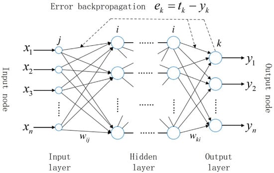
Figure 3.
BP neural network structure.
For the past few years, BP neural network technology has attracted the attention of many scholars because of its wide applicability and strong adaptive ability. Since different input parameters will produce different results, Zhao Yu et al. [13] analyzed the reasons and found that acceleration as the input parameter of the neural network can improve the stability of the recognition process, while the combination of speed and acceleration can achieve better results. For the more sensitive strain, Yang Hui et al. [65] took it as an input parameter to study the impact of different training networks and function combinations on the force identification results. The results showed that the strain parameters could effectively identify vehicle information, and the recognition accuracy was only slightly affected by the function combinations, but different training networks would have a greater impact on the recognition accuracy. Wan [66] carried out a study on the influence of different sample parameter combinations on the accuracy and efficiency of bridge moving force identification. The results showed that the BP neural network was reliable when using mixed samples of deflection and strain to provide input parameters. In order to expand the application of BP neural network technology, Tao Xing-wang et al. [67] took a cable-stayed bridge as the research object and adopted neural network technology to identify the force of heavy vehicles running on the bridge. The results showed that the identification error of vehicle weight and speed was small, and the network training output was good. Wang Xiao-hui [68] proposed a hierarchical recognition method of bridge moving load based on a BP neural network based on a Whale Optimization Algorithm (WOA) and built a moving load parameter recognition model based on a WOA-BP neural network. Sun Zong-guang et al. [69] took the operating cable force as the data test object and analyzed the change in cable force time history based on neural network technology so as to identify vehicle weight and vehicle speed. The results showed that the identification results of vehicle weight, vehicle speed and joint distribution were consistent with the reality. Subsequently, Yuan Biao [70] proposed the YOLOv5Deep SORT-BP (YD-BP) moving force recognition method based on deep learning and multi-source information fusion. Taking the wheel as the detection and tracking target, the real-time spatial position of the axle was located. Then, the location information on the axle was integrated with the dynamic response information on the bridge. Finally, the two parts of information were fused to identify the dynamic load of the vehicle on the bridge by using the powerful nonlinear high-fitting mapping capability of the BP neural network. The implementation steps of YD-BP force recognition are shown in Figure 4.
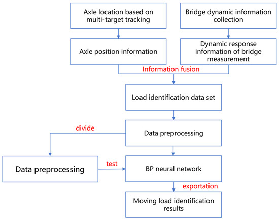
Figure 4.
YD-BP force identification implementation steps.
3.2. Machine Vision and Deep Learning
With the rapid development of machine vision and deep learning technology in the field of transportation, the identification of vehicle parameters has also achieved new achievements. As an important development direction in the future, this technology has the advantages of intelligence, non-contact and low cost, so it has been widely considered by scholars. Ojio [71] established a non-contact bridge sensor system, such as the contactless bridge weigh-in-motion system (cBWIM), using two cameras mounted on a telescope camera to monitor bridge deflection measurement and traffic conditions, respectively. The results show that cBWIM is a feasible BWIM alternative. In order to promote the development of non-contact bridge dynamic weighing, Zhou Yun et al. [72] proposed a composite inversion verification mechanism for big data influence line identification based on the mutual mapping relationship between the influence line interval and axle force interval. The results showed that this method could effectively reduce the identification error caused by too wide of an interval. Zhang Jie et al. [73] used Otsu to conduct a binary analysis of the images separated from the video, obtain the displacement change in the centroid of the feature point, convert it into the displacement change in the bridge, and deduce the size of the moving load through the displacement change. The results show that this method can accurately measure the displacement generated by the passing of a large weight moving load and analyze its load size. Dan et al. [74] proposed a force recognition method based on the integration of the BWIM system and image recognition technology and verified the reliability and accuracy of the method through multi-view 3D simulation video data and field data from a slope bridge. Based on a new concept, Feng et al. [75] estimated the contact area between the tire and the road by measuring tire deformation parameters, identified the markings on the side wall of the tire, and found the tire inflation pressure marked by the manufacturer. The results showed that the method had high measurement and recognition accuracy. Further, Kong Xuan et al. [14] reviewed the methods and application research of vehicle parameter recognition based on machine vision and deep learning technology.
4. Conclusions and Prospect
- (1)
- Due to the interference of many uncertain factors, such as road roughness, speed, and environmental noise, the calibration of the influence line, the suitability of the equation and the accuracy of axle information will have a great impact on the accuracy of BWIM. Therefore, how to deal with the impact of complex factors on the accuracy of BWIM remains to be studied.
- (2)
- At present, BWIM is mainly applicable to bridges with small and medium spans, thin load-bearing components and few vehicles. How to consider the influence of multiple vehicles and evaluate and expand the applicable scope of bridge type is an important research direction. Therefore, the applicability of BWIM needs to be improved.
- (3)
- The traditional resistance strain gauge has low accuracy and is greatly affected by temperature. Therefore, a BWIM system should not use the traditional resistance strain gauge, and a fiber Bragg grating sensor is recommended. In addition, accelerometers have the advantages of portability and affordability, and when combined with relevant technical methods, they can be effectively applied in practice.
- (4)
- The accuracy and applicability of vehicle–bridge models are the basis of MFI. At present, most MFI studies mainly focus on some simple bridge models, and research on different bridge types such as curved bridges and oblique bridges needs to be carried out. However, to improve the accuracy and applicability of the axle model, the computational time and difficulty will need to increase sharply.
- (5)
- For the time being, most studies only consider a single noise effect and cannot consider the factors of complex noise in the actual situation. At the same time, the number, layout and type of sensors will also affect the test results to a certain extent.
- (6)
- Because of the strong equation discomfort, MFI is very sensitive to noise. In recent years, MFI has mainly been solved by combining regularization and other theories, and the efficiency and accuracy of regularization methods depend on the effective selection of regularization parameters. At present, there are many studies on the regularization method of MFI, but its applicability is low. Solving the problem of unsuitability effectively is also urgent.
- (7)
- The development of sensor technology and numerical simulation provides more tools and methods for the force identification of bridge structures. Sensor data can be used to verify the accuracy of the numerical simulation, thereby improving the understanding of the stress situation of the bridge. Numerical simulations can be calibrated using sensor data to improve the accuracy and authenticity of the model. Combined with sensor data and numerical simulation results, the health of bridge structures can be monitored and assessed in real-time.
- (8)
- With the rapid development of computer technology in the fields of civil engineering and transportation, artificial neural networks, machine vision and other technologies have made major breakthroughs in the field of bridge force recognition. BP neural network technology has good robustness, self-learning ability and self-adaptation ability, but the algorithm has some defects. Deep learning and machine vision technology have the advantages of intelligence, non-contact and low cost, which is worth promoting, is being used in bridge inspection and health monitoring systems, and is a promising development direction for bridge force identification.
Author Contributions
B.-C.Y.: writing original draft. Y.Z.: data curation. T.-Y.Y.: writing—review and editing. Y.-J.Z.: supervision. M.-Y.J.: supervision. H.-Y.H.: supervision. C.-C.X.: supervision. All authors have read and agreed to the published version of the manuscript.
Funding
This work was supported by the National Key Research and Development Program of China (2021YFB1600302) and the Natural Science Foundation Research Program of Shaanxi Province (2024JC-YBON-0387).
Conflicts of Interest
Author Tian-Yun Yao was employed by Xi’an Qiao Bang Engineering Testing Co., Ltd. The remaining authors declare that the research was conducted in the absence of any commercial or financial relationships that could be construed as a potential conflict of interest.
References
- Ministry of Transport. Statistical Bulletin on Development of Transport Industry in 2022. China Communications News, 16 June 2023. [Google Scholar]
- Zhou, J.Y.; Shi, X.F.; Ruan, X. Composite extrema prediction of multi-event driven bridge traffic load effects. J. Harbin Inst. Technol. 2018, 50, 11–18. [Google Scholar]
- Gao, Q.F.; Zhang, K.; Liu, C.G. Discussions on the Impact Factor of Bridges Subjected to Moving Vehicular Loads. J. Harbin Inst. Technol. 2020, 52, 44–50. [Google Scholar]
- Moses, F. Weigh-in-motion system using instrumented bridges. Transp. Eng. J. 1979, 105, 233–249. [Google Scholar] [CrossRef]
- Ojio, T.; Yamada, K. Bridge weigh-in-motion systems using stringers of plate girder bridges. In Proceedings of the 3rd International WIM Conference, Orlando, FL, USA, 13–15 May 2002; pp. 209–218. [Google Scholar]
- Ojio, T.; Yamada, K. Bridge WIM by reaction force method. In Proceedings of the 4th International WIM Conference, Taipei, Taiwan, 20–23 February 2005; pp. 97–108. [Google Scholar]
- Deng, L.; Shi, H.; He, W. Vehicles’ BWIM based on virtual simply-supported beam method. J. Vib. Shock. 2018, 37, 209–215. [Google Scholar]
- O’Connor, C.; Chan, T.H.T. Dynamic loads from bridge strains. J. Struct. Eng. 1988, 114, 1703–1723. [Google Scholar] [CrossRef]
- Law, S.S.; Chan, T.H.T.; Zeng, Q.H. Moving force identification: A time domain method. J. Sound Vib. 1997, 201, 1–22. [Google Scholar] [CrossRef]
- Law, S.S.; Chan, T.H.T.; Zeng, Q.H. Moving force identification: A frequency and time domains analysis. J. Dyn. Syst. Meas. Control 1999, 121, 394–401. [Google Scholar] [CrossRef]
- Chan, T.H.T.; Law, S.S.; Yung, T.H.; Yuan, X.R. An interpretive method for moving force identification. J. Sound Vib. 1999, 219, 503–524. [Google Scholar] [CrossRef]
- Yu, L.; Chan, T.H.T. Moving force identification based on the frequency-time domain method. J. Sound Vib. 2003, 261, 329–349. [Google Scholar] [CrossRef]
- Zhao, Y.; Li, R.R.; Zhou, Y.J. Precision for Moving Load Identification of Bridge Structure Based on Back Propogation Neural. Network Sci. Technol. Eng. 2021, 21, 6446–6453. [Google Scholar]
- Kong, X.; Zhang, J.; Deng, L. Research Advances on Vehicle Parameter Identification Based on Machine Vision. China J. Highw. Transp. 2021, 34, 13–30. [Google Scholar]
- O’Brien, E.J.; Quilligan, M.J.; Karoumi, R. Calculating an IL from direct measurements. Proc. Inst. Civ. Eng. Bridge Eng. 2006, 159, 31–34. [Google Scholar]
- Ieng, S. Bridge influence line estimation for bridge weigh-in-motion system. J. Comput. Civ. Eng. 2015, 29, 06014006. [Google Scholar] [CrossRef]
- Yoshida, I.; Sekiya, H.; Mustafa, S. Bayesian Bridge Weigh-in-Motion and Uncertainty Estimation. ASCE-ASME J. Risk Uncertain. Eng. Syst. Part A Civ. Eng. 2021, 7, 04021001. [Google Scholar] [CrossRef]
- Zhang, H.; Chen, S.X.; Yu, M. Research on the dynamic weight identification of bridges based on temperature effect. J. Zhejiang Univ. Technol. 2017, 45, 682–687, 693. [Google Scholar]
- Zhang, L.W.; Wang, J.Q.; Chen, N. Theoretical and experimental study on a bridge weigh-in-motion iterative algorithm. J. Vib. Shock 2021, 40, 171–176. [Google Scholar]
- Wang, N.B.; Ren, W.X.; Wan, H.P. Bridge weigh-in-motion and its optimization algorithm based on dynamic strain. J. Vib. Shock 2013, 32, 116–120. [Google Scholar]
- Zhu, Q.J.; Xiao, Q.; Deng, L. Dynamic weighing method of bridge based on reaction force of support. J. China Foreign Highw. 2019, 39, 87–94. [Google Scholar]
- Zhao, H.; Tan, C.J.; Zhang, L.W. Improved Identification of Vehicular Axles in BWIM System Based on Wavelet Transform. J. Hunan Univ. (Nat. Sci.) 2016, 43, 111–119. [Google Scholar]
- He, W. Virtual Axle Method for Bridge Weigh-in-Motion Systems Requiring No Axle Detector. J. Bridge Eng. 2019, 24, 04019086. [Google Scholar] [CrossRef]
- Deng, L.; He, W.; Yu, Y.; Cai, C.S. Equivalent Shear Force Method for Detecting the Speed and Axles of Moving Vehicles on Bridges. J. Bridge Eng. 2018, 23, 04018057. [Google Scholar] [CrossRef]
- Hidehiko, S. Field Verification over One Year of a Portable Bridge Weigh-in-Motion System for Steel Bridges. J. Bridge Eng. 2019, 24, 04019063. [Google Scholar]
- Mustafa, S.; Sekiya, H.; Hirano, S.C. Iterative linear optimization method for bridge weigh-in-motion systems using accelerometers. Struct. Infrastruct. Eng. 2021, 17, 04019063. [Google Scholar] [CrossRef]
- Qian, C.Z.; Chen, C.P. Method for Moving Force Identification Using Bending Moment Influence Line. J. Dyn. Control 2016, 14, 182–185. [Google Scholar]
- Wang, N.B.; Ren, W.X.; Li, M. Moving load identification of a bridge based on influence line. J. Vib. Shock 2013, 32, 129–133. [Google Scholar]
- Wang, N.B. Study of Application Scope and Test Precision of Bridge Weigh-in-Motion Technology. Bridge Constr. 2015, 45, 36–41. [Google Scholar]
- Deng, L.; Li, S.Z.; Dan, D.H. Study on Applicability of Bridge Weigh-in-Motion Technology in Short-to Medium-span Concrete Girder Bridges. J. Hunan Univ. (Nat. Sci.) 2020, 47, 89–96. [Google Scholar]
- Zhao, H.; Wu, H.L.; Hu, Z.T. In Situ Experimental Study of the Bridge Weigh-in-motion System on a Rigid-continuous Box Girder Bridge. Highw. Eng. 2020, 45, 21–29. [Google Scholar]
- Zhang, A.M.; Wu, H.L.; Ma, P.F. The Global Effect of the Application of BWIM System to Orthotropic Steel Decks. Highw. Eng. 2017, 42, 261–267. [Google Scholar]
- He, Y.; Zhang, Y.F.; Yang, C.Q. Research on Load Identification of a Three-span Continuous Beam Bridge Based on Influence Line. Mod. Transp. Technol. 2016, 13, 48–51. [Google Scholar]
- Ren, W.X.; Zuo, X.H.; Wang, N.B. Review of Non-pavement Bridge Weigh-in-motion. China J. Highw. Transp. 2014, 27, 45–53. [Google Scholar]
- Dong, Y.; Zhao, H.; Ma, P.F. Separation of Multi-vehicle-induced Strain Signals Based on ICA. Highw. Eng. 2019, 44, 234–239, 251. [Google Scholar]
- Gong, Y.F.; Song, J.X.; Tan, G.J. Multi-vehicle bridge weigh-in-motion algorithm. J. Jilin Univ. (Eng. Technol. Ed.) 2021, 51, 583–596. [Google Scholar]
- Chen, S.Z.; Wu, G.; Feng, D.C. Development of a bridge weigh-in-motion method considering the presence of multiple vehicles. Eng. Struct. 2019, 191, 724–739. [Google Scholar] [CrossRef]
- Zuo, X.H. Multi-Vehicle Dynamic Load of Multi-Girder Highway Bridge: Identification Method and Experimental Investigation. Ph.D. Thesis, Hefei University of Technology, Hefei, China, 2020. [Google Scholar]
- Yuan, X.R.; Bu, J.Q.; Man, H.G. Function Approximation Method for Moving Load Identification. J. Vib. Shock 2000, 19, 60–62, 72, 94. [Google Scholar]
- Huang, L.; Yuan, X.R. Application of wavelet analysis in identification of moving loads on a bridge. J. China Railw. Soc. 2003, 25, 97–101. [Google Scholar]
- Yu, L.; Zhu, J.H.; Chen, M.Z. Experimental Study on Identification of Moving Vehicle Loads on A Bridge Based on Moments Method. J. Sound Vib. 2007, 105, 16–20, 156. [Google Scholar]
- Zhu, J.H.; Yu, L.; Chen, M.Z. Applicability Study on Moving Load Identification. Eng. Mech. 2007, 24, 32–36, 48. [Google Scholar]
- Law, S.S.; Chan, T.H.T.; Zhu, Q.X.; Zeng, Q.H. Regularization in Moving Force Identification. J. Eng. Mech. 2001, 127, 136–148. [Google Scholar] [CrossRef]
- Li, Q.; Lu, Q. A revised time domain force identification method based on Bayesian formulation. Int. J. Numer. Methods Eng. 2019, 118, 411–431. [Google Scholar] [CrossRef]
- Pan, C.D.; Yu, L.; Liu, H.L. Identification of moving vehicle loads on bridge structures via moving average Tikhonov regularization. Smart Mater. Struct. 2017, 26, 085041. [Google Scholar] [CrossRef]
- Liu, H.; Luo, Z.; Yu, L. A semi-convex function for both constant and time-varying moving force identification. Mech. Syst. Signal Process. 2021, 146, 107062. [Google Scholar] [CrossRef]
- Qiao, B.J.; Mao, Z.; Liu, J.X. Group sparse regularization for impact force identification in time domain. J. Sound Vib. 2019, 445, 44–53. [Google Scholar] [CrossRef]
- Qiao, B.J.; Zhang, X.W.; Gao, J.W. Sparse deconvolution for the large-scale ill-posed inverse problem of impact force reconstruction. Mech. Syst. Signal Process. 2017, 83, 93–115. [Google Scholar] [CrossRef]
- Qiao, B.J.; Zhang, X.W.; Gao, J.W. Impact-force sparse reconstruction from highly incomplete and inaccurate measurements. J. Sound Vib. 2016, 376, 72–94. [Google Scholar] [CrossRef]
- Qiao, B.J.; Zhang, X.W.; Wang, C.X. Sparse regularization for force identification using dictionaries. J. Sound Vib. 2016, 368, 71–86. [Google Scholar] [CrossRef]
- Pan, C.D.; Yu, L.; Liu, H.L. Moving force identification based on redundant concatenated dictionary and weighted l1-norm regularization. Mech. Syst. Signal Process. 2018, 98, 32–49. [Google Scholar] [CrossRef]
- Zhong, J.W.; Liu, H.L.; Yu, L. Sparse regularization for traffic load monitoring using bridge response measurements. Measurement 2018, 131, 173–182. [Google Scholar] [CrossRef]
- Pan, C.D.; Yu, L.; Liu, H.L. Sparse regularization based moving force identification under unknown initial conditions. J. Vib. Eng. 2018, 31, 734–743. [Google Scholar]
- Zhong, J.W.; Liu, H.L.; Yu, L.; Pan, C.D. Compressed sensing for moving force identification using redundant dictionaries. Mech. Syst. Signal Process. 2020, 138, 106535. [Google Scholar]
- Zhang, Z.H. Moving Load Identification Based on Dictionary Learning. Master’s Thesis, Hefei University of Technology, Hefei, China, 2020. [Google Scholar]
- Liu, J.; Sun, X.S.; Han, X. A novel computational inverse technique for load identification using the shape function method of moving least square fitting. Comput. Struct. 2014, 114, 127–137. [Google Scholar] [CrossRef]
- Sun, Y.; Luo, L.; Chen, K. A time-domain method for load identification using moving weighted least square technique. Comput. Struct. 2020, 234, 106254. [Google Scholar] [CrossRef]
- Chen, Z.; Yu, L. Bridge moving load identification and regularization matrix selection based on TGSVD. J. Vib. Meas. Diagn. 2015, 35, 24–29, 184. [Google Scholar]
- Chen, Z.; Chan, T.H.T. A truncated generalized singular value decomposition algorithm for moving force identification with ill-posed problems. J. Sound Vib. 2017, 401, 297–310. [Google Scholar] [CrossRef]
- Chen, Z.; Wei, W.J.; Yu, L. Bridge Moving Load Identification Based on PPTSVD. J. Vib. Meas. Diagn. 2018, 38, 727–732, 871. [Google Scholar]
- Wang, Z. Study on Influencing Factors of Moving Force Identification Accuracy. Master’s Thesis, North China University of Water Resources and Electric Power, Zhengzhou, China, 2020. [Google Scholar]
- Chen, Z.; Chan, T.H.T.; Nguyen, A. Moving force identification based on modified preconditioned conjugate gradient method. J. Sound Vib. 2018, 423, 100–117. [Google Scholar] [CrossRef]
- Chen, Z.; Yu, L. Identification of Dynamic Axle Loads on Bridge based on Pretreatment Conjugate Gradient Method. In Collection of Abstracts of the 9th National Symposium on Vibration Theory and Application; Zhejiang University Press: Hangzhou, China, 2007; pp. 126–127. [Google Scholar]
- Chen, Z.; Chan, T.H.T.; Yu, L. Comparison of regularization methods for moving force identification with ill-posed problems. J. Sound Vib. 2020, 478, 115349. [Google Scholar] [CrossRef]
- Yang, H.; LI, F.G.; Yan, W.M. Moving Load Identification and Experimental Verification of Beam Bridge Based on Dynamic Strain and ANN. J. Vib. Meas. Diagn. 2018, 38, 305–313, 419. [Google Scholar]
- Wan, L.X. Moving load parameter identification of bridge based on BP neural network. Henan Sci. Technol. 2023, 42, 82–85. [Google Scholar]
- Tao, X.W.; Sun, Z.G.; Chen, Y.F. Identification of Vehicle Load and Speed on Cable-stayed Bridge Based on Monitoring Response. J. Highw. Transp. Res. Dev. 2019, 36, 87–93. [Google Scholar]
- Wang, X.H.; Zhang, B.R.; Tao, Z.R. Research on Load parameter identification of Bridge Moving Vehicle based on WOA-BP neural Network. Chin. Foreign Road 2023, 43, 85–93. [Google Scholar]
- Sun, Z.G.; Chen, Y.F. Online vehicle speed and weight identification based on cable force monitoring of cable-stayed bridge. J. Vib. Shock. 2020, 39, 134–141, 149. [Google Scholar]
- Yuan, B. Dynamic Load Recognition of Small and Medium Bridge Vehicles Based on Deep Learning and Multi-Source Information Fusion. Master’s Thesis, Chang’an University, Xi’an, China, 2023. [Google Scholar]
- Ojio, T.; Carey, C.H.; O’Brien, E.J. Contactless Bridge Weigh-in-Motion. J. Bridge Eng. 2016, 21, 04016032. [Google Scholar] [CrossRef]
- Zhou, Y.; Hu, J.X.; Zhou, S. Research on contactless influence line identification method and composite inversion mechanism based on interval analysis. Earthq. Eng. Eng. Dyn. 2021, 41, 24–34. [Google Scholar]
- Zhang, J.; Bai, P.X.; Du, W.K. Bridge moving load recognition based on digital image method. Henan Sci. 2022, 40, 1728–1735. [Google Scholar]
- Dan, D.H.; Ge, L.F.; Yan, X.F. Identification of moving loads based on the information fusion of weigh-in-motion system and multiple camera machine vision. Measurement 2019, 144, 155–166. [Google Scholar] [CrossRef]
- Feng, M.Q.; Leung, R.Y. Application of computer vision for estimation of moving vehicle weight. IEEE Sens. J. 2020, 21, 11588–11597. [Google Scholar] [CrossRef]
Disclaimer/Publisher’s Note: The statements, opinions and data contained in all publications are solely those of the individual author(s) and contributor(s) and not of MDPI and/or the editor(s). MDPI and/or the editor(s) disclaim responsibility for any injury to people or property resulting from any ideas, methods, instructions or products referred to in the content. |
© 2024 by the authors. Licensee MDPI, Basel, Switzerland. This article is an open access article distributed under the terms and conditions of the Creative Commons Attribution (CC BY) license (https://creativecommons.org/licenses/by/4.0/).