Abstract
With the development of control technology, the uniflow scavenging opposed-piston (USOP) diesel engine has shown unique advantages in energy savings and emission reductions. Due to the uniflow scavenging process, unstable scavenging performance has become the key problem in the development process of the USOP diesel engine, and the intake structure is an effective method for regulating scavenging performance. This study verifies the simulation model based on experimental data and then analyzes the influence of the intake port structure through simulations. On the one hand, this study explores the interference mechanism and application rules of two structures: composite intake ports and dual independent intake ports. The results show that the external alignment structure should be used under all operating conditions for composite intake ports. For dual independent intake ports, the internal alignment structure should be used at high swirl strength, and the external alignment structure should be used at low swirl strength. On the other hand, the dual independent intake ports matching the dual intake channels can improve scavenging performance while reducing supply power. The conclusion provides a reference for the design of the intake structure of the USOP diesel engine from many aspects.
1. Introduction
The uniflow scavenging opposed-piston (USOP) engine has high thermal efficiency, high power density, and good balance [1], making it suitable for road vehicles, non-road machinery, military equipment, low-altitude unmanned aerial vehicles [2], etc. Research on the USOP engine has been stalled by emissions problems [3]. With the progress of control technology, the emission problems of USOP engines have been solved [4,5], and they even has significant advantages in NOX emission control [3]. Related research has emerged again. Common USOP engine types include opposed-piston two-stroke (OP2S), opposed-piston opposed cylinder (OPOC), opposed free piston linear generator (OFPLG), and two-stroke rod-less opposed pistons engine (2S-ROPE) [6]. The OP2S engine is one of the most stable structural forms [7], and Achates actively promotes its industrial application [8]. The OPOC engine has only one crankshaft [9], but connecting rods that are too long will easily damage the structural strength. With the development of electric vehicles, the OFPLG, as part of range extenders, has developed rapidly [10,11]. The OFPLG has canceled the crank connecting rod mechanism, which also introduces the problem of controlling the piston motion trajectory. In recent years, research on the 2S-ROPE model using a turntable structure to solve piston motion control without crank linkage has emerged [12,13]. Therefore, solving the general technical problems associated with various USOP models is very important.
The conventional diesel engine airports are installed on the cylinder head, and the intake channel design changes the airflow state. The annular airports of the USOP engine are arranged on the cylinder liner, making it difficult to effectively control the airflow characteristics of all annular airports through the intake channel; this, the intake structure becomes the key parameter for controlling the airflow characteristics of the USOP engine.
Uniflow scavenging is the air exchange mode with the highest scavenging efficiency in two-stroke engines [14]. The uniflow scavenging structure of the USOP engine forgoes the valve mechanism of conventional engines. The intake and exhaust ports are directly arranged on both sides of the cylinder liner, and the movement of the two pistons directly controls the opening and closing of the intake ports. Unlike conventional models, the USOP engine mainly controls the intake flow characteristics through the intake structure. Researchers have conducted many studies on different intake structures [15]. Zhou et al. [16] studied the intake port inclination angle. They found that with an increase in the intake port inclination angle, the scavenging rate decreases, but the scavenging efficiency increases, and the optimal inlet inclination angle is 20°. Changming, H [17] proposed a study on the radial inclination angle of the intake port and found that the 5.01% scavenging efficiency and the 12.1% capture quality could be improved by optimizing the inlet inclination angle and valve timing. Mattarelli et al. [18] focused on the findings of the two previous studies regarding the intake port inclination angle and the radial intake port inclination angle. They found that the optimal values of the two inclination angles were 15°. According to O’Donnell [19] et al., increasing the intake port inclination angle can effectively increase the in-cylinder swirl flow and angular momentum, but this adjustment will deteriorate scavenging performance, and a large amount of exhaust gas will remain in the cylinder center. The optimal intake port inclination angles of the above studies are inconsistent, and the intake port structure forms are also inconsistent. Therefore, it is known that the optimal intake port under different application conditions is inconsistent, and it is necessary to obtain a universal research conclusion to provide a reference for intake port selection.
The commonly used intake port structures for USOP engines include swirl intake ports and straight intake ports. The swirl intake port is used to generate the intake swirl flow so that the scavenging airflow path moves from the cylinder center to the cylinder wall [20], and the intake swirl flow reduces the axial velocity of the scavenging airflow, thereby reducing the scavenging rate. The straight intake port does not produce intake swirl flow, which is conducive to improving the axial velocity of the scavenging airflow; therefore, the composite intake ports and dual independent intake ports containing swirl ports and straight ports are commonly used intake structures. When using composite intake ports, the airflow characteristics of the swirl part and the straight part are different, and the two parts of the airflow will collide, affecting the control of the intake flow state. It is necessary to explore the influence of the layout of the composite intake ports on the comprehensive performance. Dual independent intake ports can reduce the air collision problem in composite intake ports. Nevertheless, under the same total port height, the cross-sectional area of the dual independent intake ports is lower than that of the composite intake ports, which affects the flow performance of the intake ports. It is necessary to explore the performance differences between the dual independent intake ports and the composite intake ports, so as to provide a reference for the selection of the intake port structure.
The performance of the USOP engine changes greatly under different operating conditions, and the demand for the scavenging airflow changes greatly. In this study, the dual intake channels invented by our team are used, allowing for independent adjustment of the intake pressure in the dual intake channels. By exploring the application characteristics of dual intake channels combined with dual independent intake ports, the control ability of intake flow characteristics of the USOP engine is further enhanced.
In this study, a computational fluid dynamics (CFD) simulation model of the USOP diesel engine was established, and the experimental data of the cylinder pressure curve and airflow characteristics verified the accuracy of the simulation model. Then, the validated model was used to study the working characteristics of the intake ports. The performance difference between composite intake ports and dual independent intake ports was explored under high swirl intensity, and the influence mechanism of performance differences between different intake ports was determined. Then, this study reduced the in-cylinder swirl strength and explored the working law of different intake ports under different working conditions. Finally, based on the dual intake channels developed by the team, the application characteristics and energy efficiency characteristics of the dual independent intake ports under different intake pressures were explored. The conclusion of this paper provides a reference for the selection of the USOP diesel engine intake structure.
2. Model Configuration and Analysis Methods
2.1. Model Configuration
The dual intake channels are used in the simulation model of this paper, and the structure with dual intake channels in Figure 1 is used to illustrate the operation process of the USOP diesel engine. In the dual intake channels, the swirl channel independently controls the airflow characteristics in the swirl port, and the straight channel independently controls the airflow characteristics in the straight port. In Figure 1, the swirl ports and the straight ports are opened simultaneously. The USOP diesel engine does not have a valve mechanism, and the reciprocating movement of the intake and exhaust pistons controls the opening and closing of the intake and exhaust ports. Due to the uniflow scavenging process, the intake and exhaust ports will open simultaneously, fresh air will enter the cylinder from the intake port, and the exhaust gas will be discharged from the exhaust port. Due to the direct contact between fresh air and exhaust gas, mixing fresh air and exhaust gas in the uniflow scavenging process is easy. In order to avoid the reduction of scavenging efficiency caused by exhaust gas mixing, the intake tumble flow should be as low as possible.
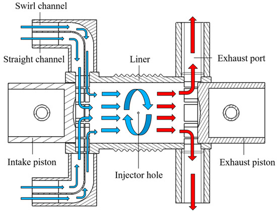
Figure 1.
Structure configuration of the USOP engine.
In order to ensure that the in-cylinder airflow has high turbulent kinetic energy (TKE) at the spraying time, an intake swirl motion is generated through the swirl intake port. More importantly, the intake swirl flow is a key factor in adjusting the scavenging path. Figure 2 shows scavenging path differences under different swirl intensities, where red indicates exhaust gas, blue indicates fresh air, and swirl intensity increases with the swirl ratio (SR). The variation law of the scavenging path with the swirl intensity in the figure shows that with increased swirl intensity, the scavenging path will move from the cylinder center to the cylinder wall. In Figure 2, when the SR rises from 1.1 to 1.9, the scavenging path is closer to the cylinder wall, and more exhaust gas appears in the cylinder center. However, the scavenging path of the same swirl strength will also change under different operating conditions.
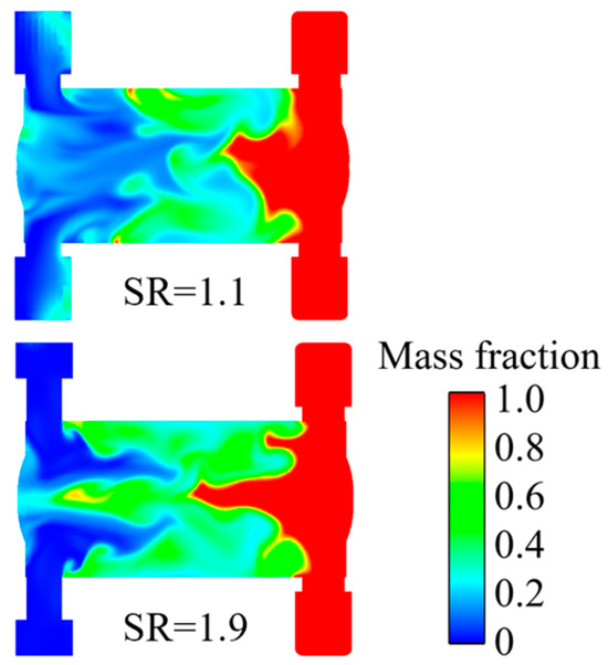
Figure 2.
Scavenging paths for different swirl intensities.
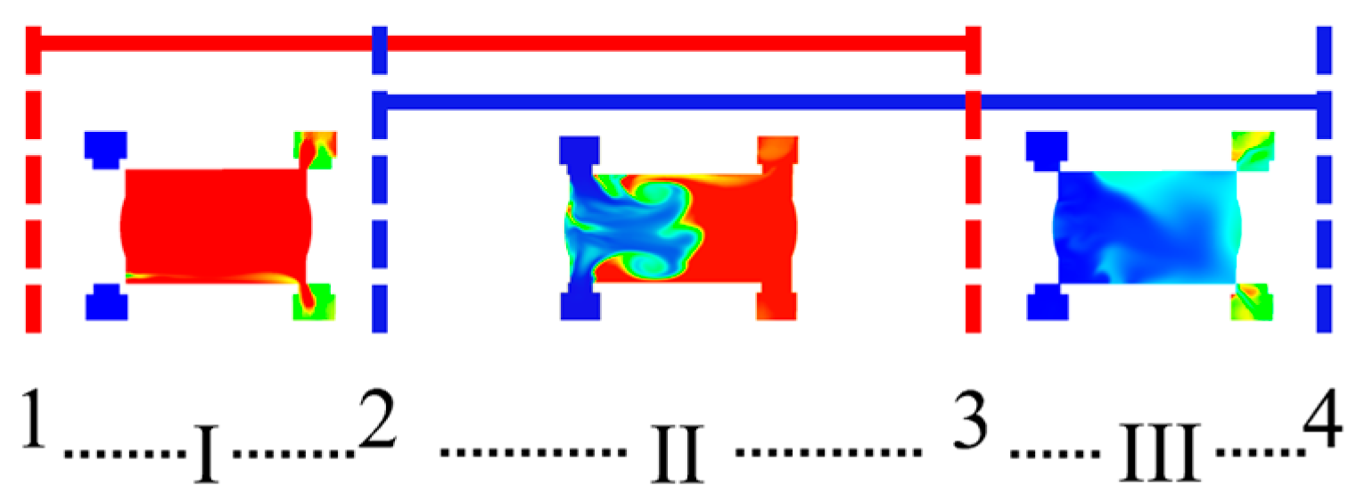
As shown in Figure 3, the uniflow scavenging process of the USOP diesel engine can be divided into three stages: stage I is the free exhaust stage, stage II is the scavenging stage, and stage III is the post-charge stage. The interval represented by the red line from position 1 to position 3 in the figure is the exhaust port opening interval. The exhaust port is open at position 1, and the exhaust port is closed at position 3. The interval indicated by the blue line from position 2 to position 4 in the figure is the intake port opening interval. The intake port is open at position 2, and the intake port is closed at position 4. In summary, stage I is from position 1 to position 2, during which the in-cylinder exhaust gas is quickly discharged from the exhaust port. Increasing the interval of the free exhaust stage can effectively reduce the cylinder pressure at the intake opening time, thus reducing the possibility of the exhaust gas flowing back to the intake channel. However, the long exhaust phase will affect the ability of the in-cylinder gas to perform work and reduce its thermal efficiency. Stage II is from position 2 to position 3. In this interval, the intake and exhaust ports open simultaneously, and the in-cylinder exhaust gas is discharged from the exhaust port under the impetus of fresh air. Scavenging power comes from the pressure difference, making the in-cylinder pressure and intake pressure are critical when the intake port opens in stage II. If the intake pressure is lower than the in-cylinder pressure when the intake port opens, the exhaust gas in the cylinder will flow back to the intake channel. If the intake pressure is higher than the in-cylinder pressure when the intake port opens, there will be no exhaust backflow. Stage III is from position 3 to position 4, in which the intake port opens and the exhaust port closes to increase the in-cylinder air mass by using the intake inertia after the scavenging phase.
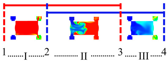
Figure 3.
Scavenging phase diagram of the opposed-piston two-stroke.
Table 1 shows the structural parameters of the 120 mm cylinder diameter USOP diesel engine. The only structural variable in this study is the intake structure, which will be replaced in different cases, and the number of intake ports and the total intake port width remain unchanged. This study adopts a high-pressure common rail fuel injection method. Table 2 shows the operating parameters at 2600 rpm.

Table 1.
Structural parameters of the USOP engine.
Table 2.
Operational parameters of the USOP engine.
2.2. CFD Modeling and Validation
This study used the CONVERGE software [21] to analyze the USOP diesel engine. The simulation models are shown in Table 3, and the relevant mechanisms have been widely applied. Related studies have also demonstrated the simulation reliability of the CONVERGE software for flow, spray, and combustion [19,22,23]. The experimental data in the model validation section is consistent with the literature [24].
Table 3.
Mathematical models and mechanisms.
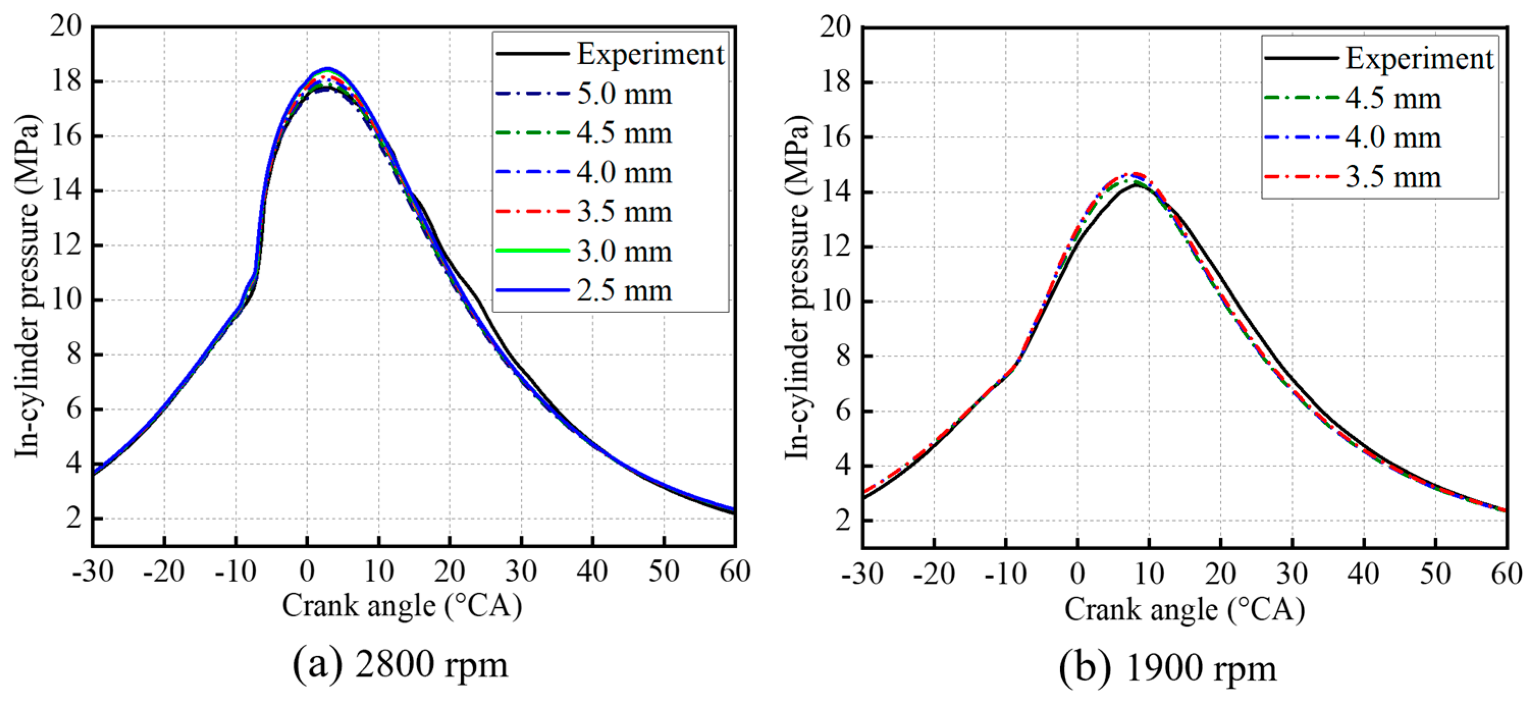
The experimental data in the cylinder pressure verification were mainly obtained through the bench test shown in Figure 4. The test bench is equipped with a dynamometer, and cylinder pressure data are obtained through cylinder pressure sensors; the experimental process used 0# diesel. In order to fully verify the simulation accuracy of the simulation model on the cylinder pressure change. The cylinder pressure verification was carried out at 2800 rpm and 1900 rpm. Firstly, 2800 rpm cylinder pressure verification was performed, and the verification results are shown in Figure 5a. A large base mesh size range of 2.5 mm to 5.0 mm was chosen for the first model validation. The cylinder pressure curve in the figure shows that the simulation models with all mesh sizes effectively simulate the cylinder pressure variation trend. When the mesh size is reduced to 3.0 mm, the cylinder pressure curve coincides with the cylinder pressure curve at 2.5 mm, which indicates that the calculation results converge. However, as the mesh size decreases, the calculation time increases rapidly. After weighing the accuracy of cylinder pressure variation and the calculation time, the 4.5 mm base mesh size is ideal. Three-level mesh encryption is used in this model, and the minimum mesh size is calculated as 4.5/23 = 0.5625 mm. To further verify the accuracy of this mesh size for multi-speed applications, cylinder pressure verification was performed again at 1900 rpm. The selected mesh size range was reduced from 3.5 mm to 4.5 mm, and the cylinder pressure curve results are shown in Figure 5b. When the mesh size is 4.5 mm, the maximum simulation error is 7.78%, which meets the accuracy requirements. Further reducing the mesh size does not significantly improve the simulation accuracy. In summary, a 4.5 mm base mesh size was selected for simulation analysis in this study, and three-level fixed mesh encryption and three-level adaptive mesh encryption are used in the simulation. The scavenging performance of the USOP diesel engine fluctuates significantly, and the scavenging process significantly impacts the overall performance. This study will focus on the optimization mechanism of scavenging performance. The simulation accuracy of the airflow mass rate and the swirl intensity as been verified.
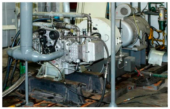
Figure 4.
Prototype bench.
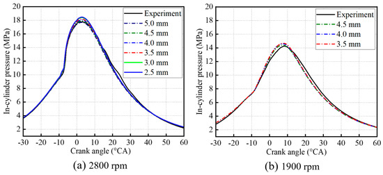
Figure 5.
Validation of cylinder pressure at different speeds.
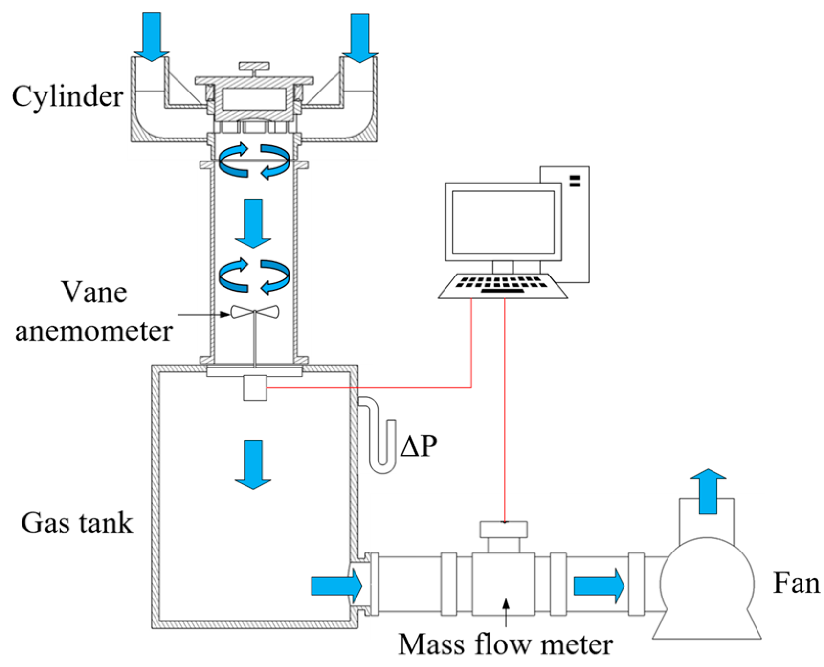
Figure 6 shows the schematic diagram of the steady-flow test bench. The intake structure is installed at the cylinder, and the gas flow is driven by a fan at the back of the steady flow test bench. After flowing through the structure to be tested, the airflow exhibits regular swirl characteristics, which will be measured by the vane anemometer at the back end. Subsequently, the airflow will continue to flow into the gas tank, which is equipped with a U-tube differential pressure meter, which will display the pressure difference between the pressure in the gas tank and the atmospheric pressure in real-time. The in-cylinder pressure is the pressure at the back end of the structure to be tested, and the intake pressure of the structure to be tested is atmospheric pressure. Therefore, the pressure measured by the U-tube differential pressure meter is the pressure difference between the inlet and outlet of the structure to be tested. Subsequently, the gas flows through the mass flow meter to measure the real-time mass flow in the steady flow test bench, and the mass flow in the system is consistent with the intake mass flow of the structure to be tested.

Figure 6.
Schematic diagram of the steady flow test bench.
Finally, the gas is discharged through the fan. The steady-flow test bench used is similar to the one in the study by Yang [35], except that it is supplemented with the function of testing in-cylinder swirl strength. During the simulation of the in-cylinder airflow characteristics, the base grid size is 4.5 mm.
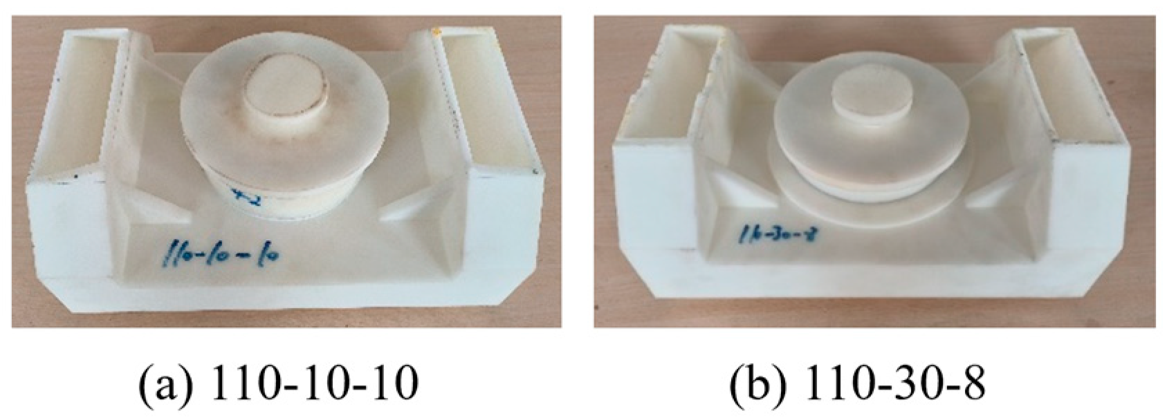
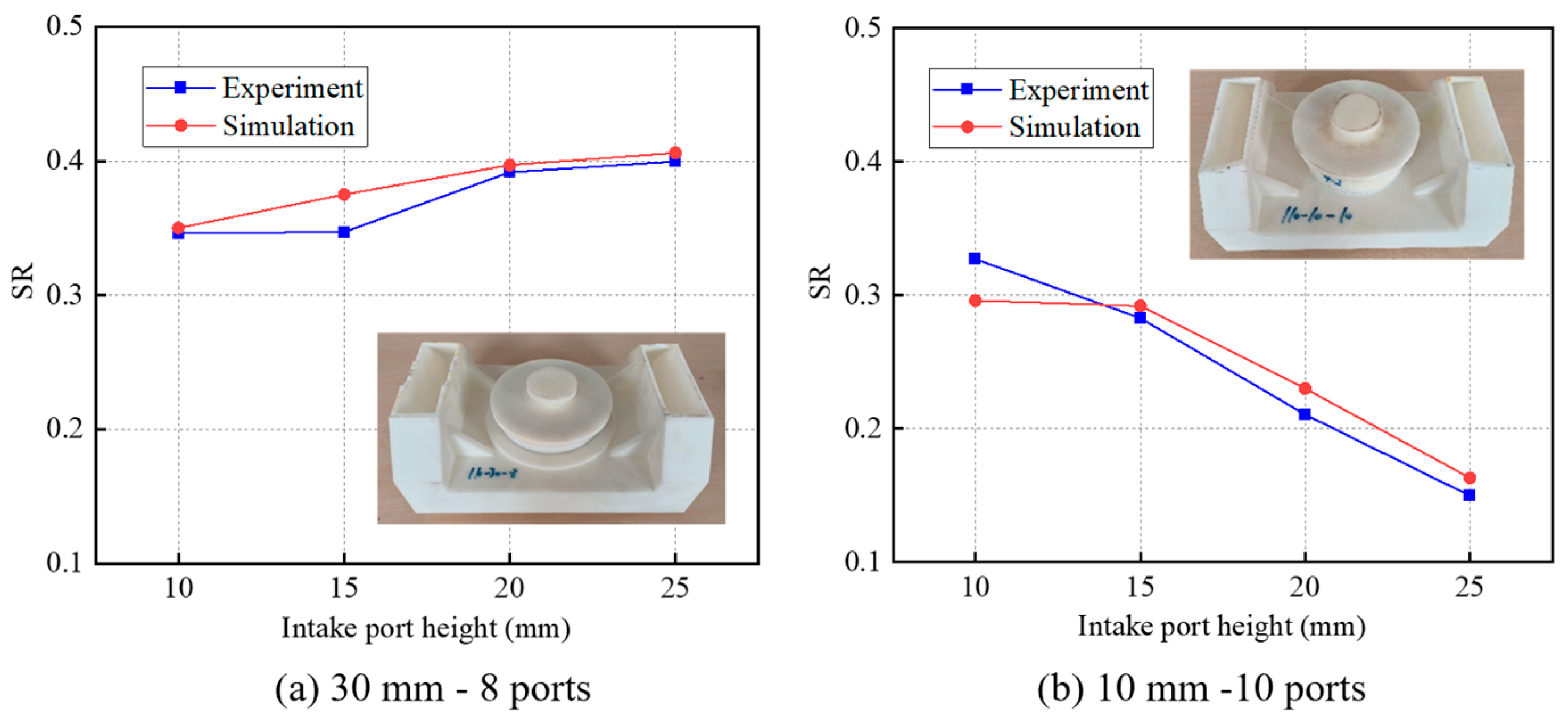
The two intake structures shown in Figure 7 are tested in the simulation and experimental process, and the intake port inclination angle is 15°. As shown by the red arrow in Figure 7a, the cylinder diameter is 110 mm, and the intake wall thickness is 10 mm. There are ten intake ports, and the intake port width is 30 mm. The cylinder diameter of Figure 7b is 110 mm, and the intake wall thickness is 30 mm. There are eight intake ports, and the intake port width is 37.5 mm.
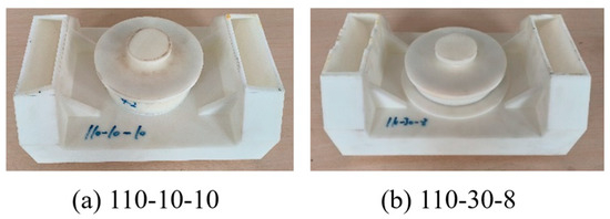
Figure 7.
Two types of intake port structure.
Airflow characteristics at intake port openings of 10 mm, 15 mm, 20 mm, and 25 mm were tested using the steady-flow test bench. During each test, the measurement parameters were recorded after the measurement parameters, such as the U-tube differential pressure meter, were stable. The test was repeated three times under each intake port opening, and the final experimental results were taken as the average of the three trials.
If there is a large deviation of the experimental value, the results with large test errors are discarded, and a new experiment is added. Figure 8 and Figure 9 show the verification results of mass flow rate and swirl ratio, respectively. The maximum simulation error of the mass flow rate is 3.8%, and the maximum simulation error of the swirl ratio is 9.2%. Therefore, it is judged that the simulation results of the simulation model for flow characteristics are ideal.
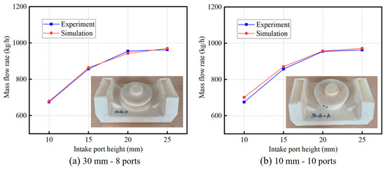
Figure 8.
Simulation accuracy verification of mass flow rate.

Figure 9.
Simulation accuracy verification of swirl ratio.
2.3. Intake Port Structure
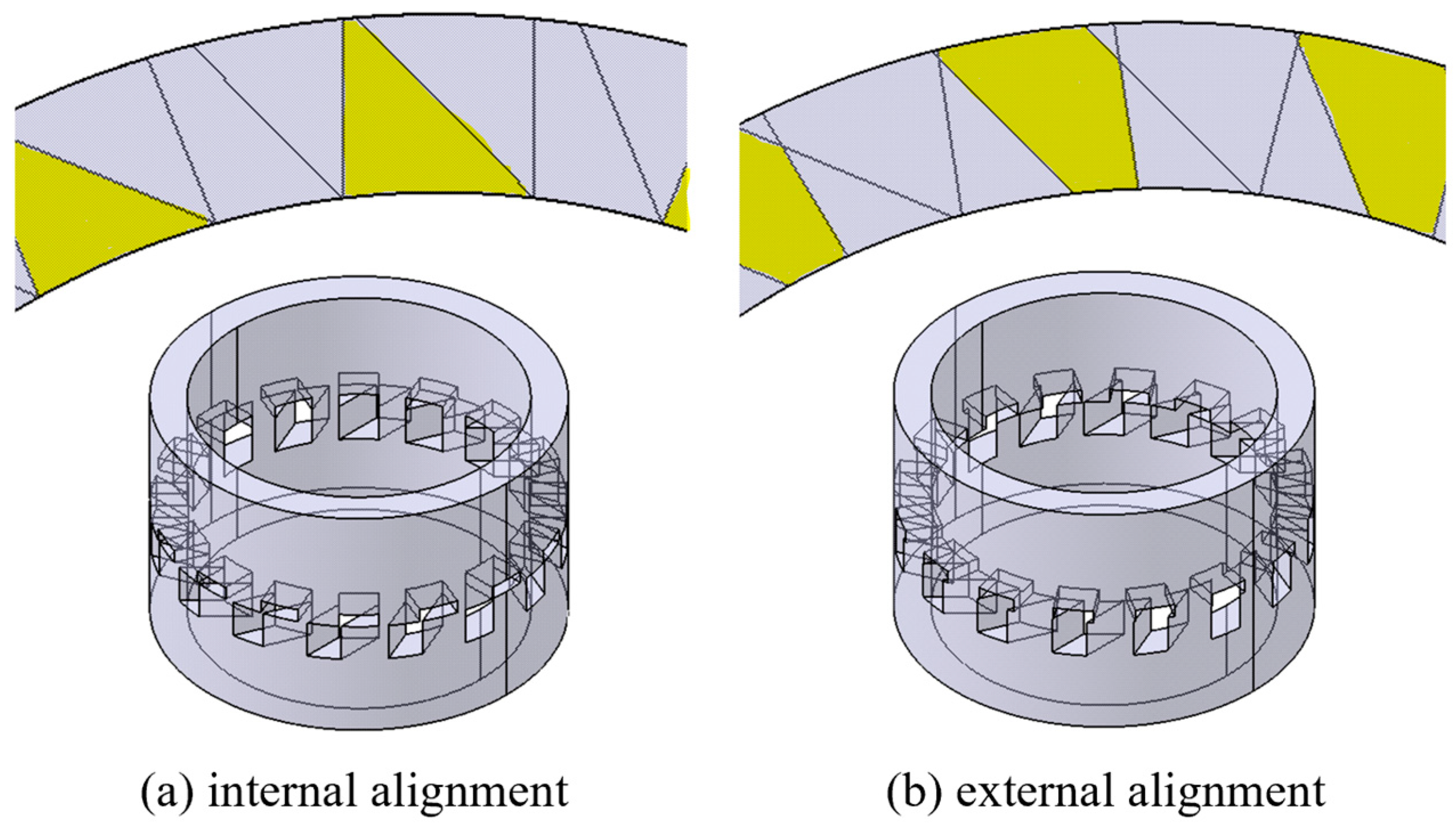
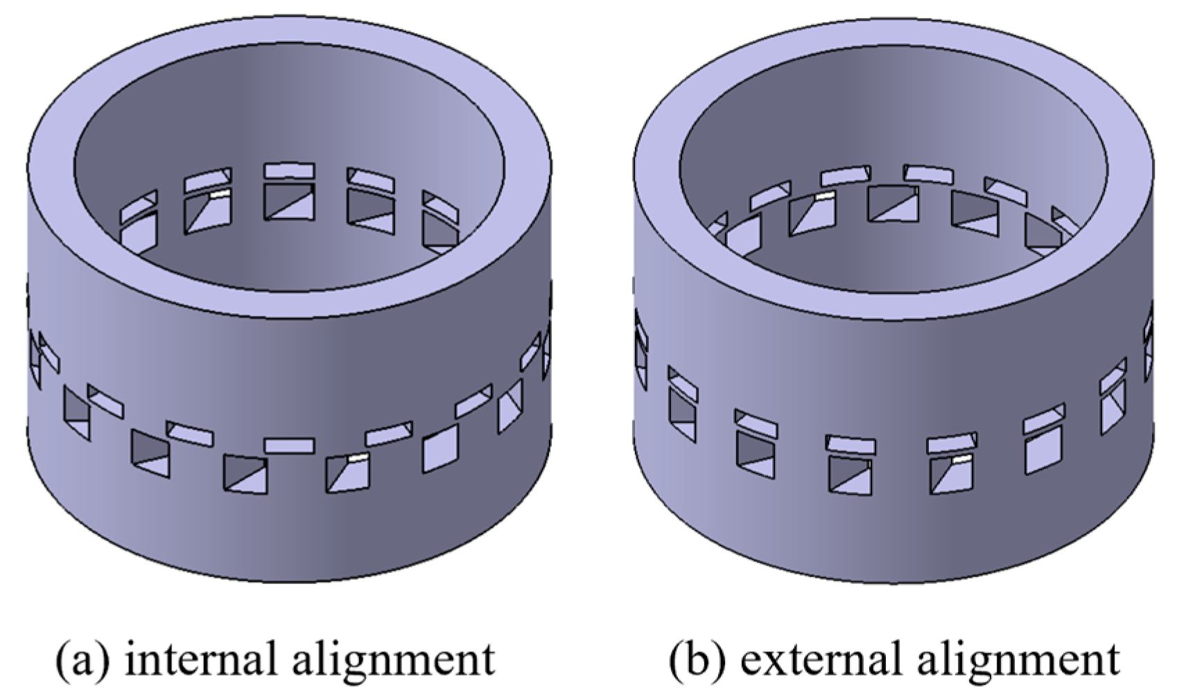
This study mainly explores the performance difference between the dual independent intake ports and the composite intake ports, as well as the intake port interference between the swirl intake port and the straight intake port. Figure 10 shows the composite intake port structure with two different relative positions of the intake ports. The swirl intake port and straight intake port of the composite intake ports are connected, and the airflow of the two intake ports interfere with one another. Figure 10a shows the internal alignment layout. The widths of the swirl intake port and the straight intake port align as much as possible on the inner surface. Figure 10b shows the external alignment layout. The widths of the swirl intake port and the straight intake port align as much as possible on the outer surface. The yellow area in Figure 10 represents the contact surface, and the contact surface of the internal alignment layout is smaller than that of the external alignment. The contact of internal alignment mainly occurs before the airflow enters the cylinder, and the swirl flow has formed in the swirl intake port. The contact of external alignment mainly occurs when the airflow enters the intake port, and the regular swirl flow initially forms in the swirl intake port. Figure 11 shows the installation effect of the two intake structures on the cylinder liner.
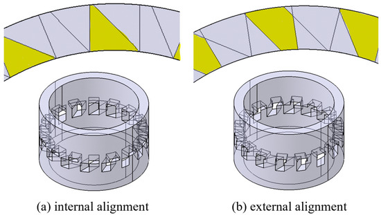
Figure 10.
Composite intake ports alignment and contact surface.
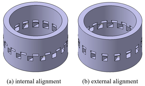
Figure 11.
Dual independent intake ports alignment.
There is no base surface between the ports of the dual independent intake ports, and the interference between the swirl intake airflow and the straight intake airflow occurs after entering the cylinder. Therefore, the dual independent intake ports are mainly used for comparison with the composite intake ports to determine the impact of the intake port contact surface on the airflow characteristics.
2.4. Evaluation Criteria
Before defining the scavenging parameters, some basic parameters are defined. MC represents the total air mass passing through the intake port in each cycle, MT represents the in-cylinder total mass after the scavenging, and MIC represents the gas mass when the fresh air in the intake channel flow state completely fills the cylinder.
Equation (1) [36] defines the delivery ratio (DR), an important parameter that reflects the air supply mass of the USOP engine. The larger the DR, the greater the air supply mass. The ideal DR range is from 1.2 to 1.4 [37]. The working mode of the USOP diesel engine makes it impossible for fresh air to completely remove exhaust gas at a DR of 1.0. Under this premise, when the DR is less than 1.0, the fresh air must be unable to completely remove the in-cylinder exhaust gas, and the scavenging process is imperfect. When the DR is between 1.0 and 1.2, the scavenging process may still be imperfect, but this DR range is also relatively ideal. When the DR exceeds 1.4, the scavenging process is completed. An excessive DR only increases the loss of gas supply power, and the improvement of scavenging performance is not significant.
Fresh air trapped mass (TM) represents the actual in-cylinder fresh air mass after scavenging. In the subsequent analysis of this paper, TM is used as a quantitative judgment parameter for assessing the scavenging performance. Under the same boundary conditions, a larger TM indicates better scavenging performance, and a smaller TM value indicates poorer performance. Equation (2) defines scavenging efficiency (SE), and under the same boundary conditions, a larger SE indicates a better scavenging performance. Both TM and SE are used as important parameters to evaluate scavenging performance. The comparison of SE is affected by MT, while TM can intuitively assess the performance difference without being affected by redundant parameters.
Equation (3) defines charging efficiency (CE). According to the definition, CE reflects the air capture capacity of the scavenging structure, and the higher the CE, the better the air capture capacity.
As shown in Equation (4), the swirl ratio (SR) is defined as the ratio of the rotational angular velocity of the in-cylinder airflow to the angular velocity of the crankshaft [21]. The SR is a key parameter for assessing the swirl strength of the in-cylinder airflow. The larger the SR, the greater the swirl strength, and the greater the turbulent kinetic energy (TKE). With the increase of the SR, the in-cylinder scavenging path moves from the cylinder center to the cylinder wall; conversely, reducing the SR can make the scavenging path move from the cylinder wall to the cylinder center. Adjusting the in-cylinder SR is the main method for optimizing the scavenging performance.
Most of the in-cylinder motion of the USOP diesel engine is swirl motion, and in-cylinder swirl motion is the main source of TKE; therefore, the numerical changes in TKE can reflect the changes in in-cylinder swirl flow. The greater the swirl flow, the greater the TKE, and the more conducive to the atomization and decomposition of direct injection fuel. The equivalent ratio is an important parameter for assessing the uniformity of the in-cylinder mixture distribution, defined as the ratio of air required in the combustion process to the actual amount of air supplied. The equivalent ratio is greater than 1, indicating that the gas supply is insufficient and it is a concentrated mixture. The equivalent ratio is less than 1, indicating that the gas supply is sufficient and it is a dilute mixture. In the case of the same total equivalent ratio, the in-cylinder equivalent ratio cloud map can reflect the oil and gas distribution in different areas. The more uniform the equivalent ratio cloud map, the more beneficial the combustion process. The cylinder pressure curve and the heat release rate curve can reflect the development of the combustion process. Under the same boundary conditions, the higher the cylinder pressure and heat release rate, the faster the combustion. Indicated mean effective pressure (IMEP) is a key parameter for assessing the performance of the complete cycle process. Under the same boundary conditions, the higher the IMEP, the better the overall performance. The maximum exhaust gas backflow mass (BM) is defined as the maximum exhaust gas mass returned from the cylinder to the intake channel in each cycle. The lower the BM value, the less adverse the impact on the scavenging performance.
3. Result and Discussion
3.1. Intake Port Structural Characteristics
3.1.1. Scavenging Performance Difference
In Table 4, Case 2 uses external alignment composite intake ports, Case 3 uses internal alignment composite intake ports, Case 4 uses internal alignment dual independent intake ports, and Case 5 uses external alignment dual independent intake ports. Table 4 shows the scavenging performance of the four cases under a 45° inclination angle of the swirling intake port, an intake pressure of 1.473 bar, and other operating parameters are consistent with those in Table 2. According to the table, the DR is around 1.0, indicating that the air supply is slightly insufficient. Under this condition, the performance of Case 2 is significantly better than that of the other cases, indicating that the external alignment composite intake ports can significantly improve scavenging performance. However, there is no obvious performance difference between the internal and external alignment for the dual independent intake port structure, which indicates that the significant performance difference will occur only when the swirl intake ports are directly connected to the straight intake ports. The above results show that dual independent intake ports effectively solve the problem of air interference between different intake ports. The scavenging performance of dual independent intake ports is significantly higher than that of composite intake ports. Under the external alignment layout, the scavenging performance of composite intake ports is significantly higher than that of dual independent intake ports. In summary, it is concluded that there is no obvious performance difference between dual independent intake ports and composite intake ports, which can be applied according to the service conditions.
Table 4.
Scavenging performance of four cases with 45° intake inclination.
The main in-cylinder airflow movement of the USOP engine is the swirl movement around the cylinder axis, and the in-cylinder swirl intensity is an important factor affecting the scavenging path. In addition, the in-cylinder swirl will also significantly impact fuel atomization and oil and gas distribution, and different swirl intensities should be formed according to the working conditions.
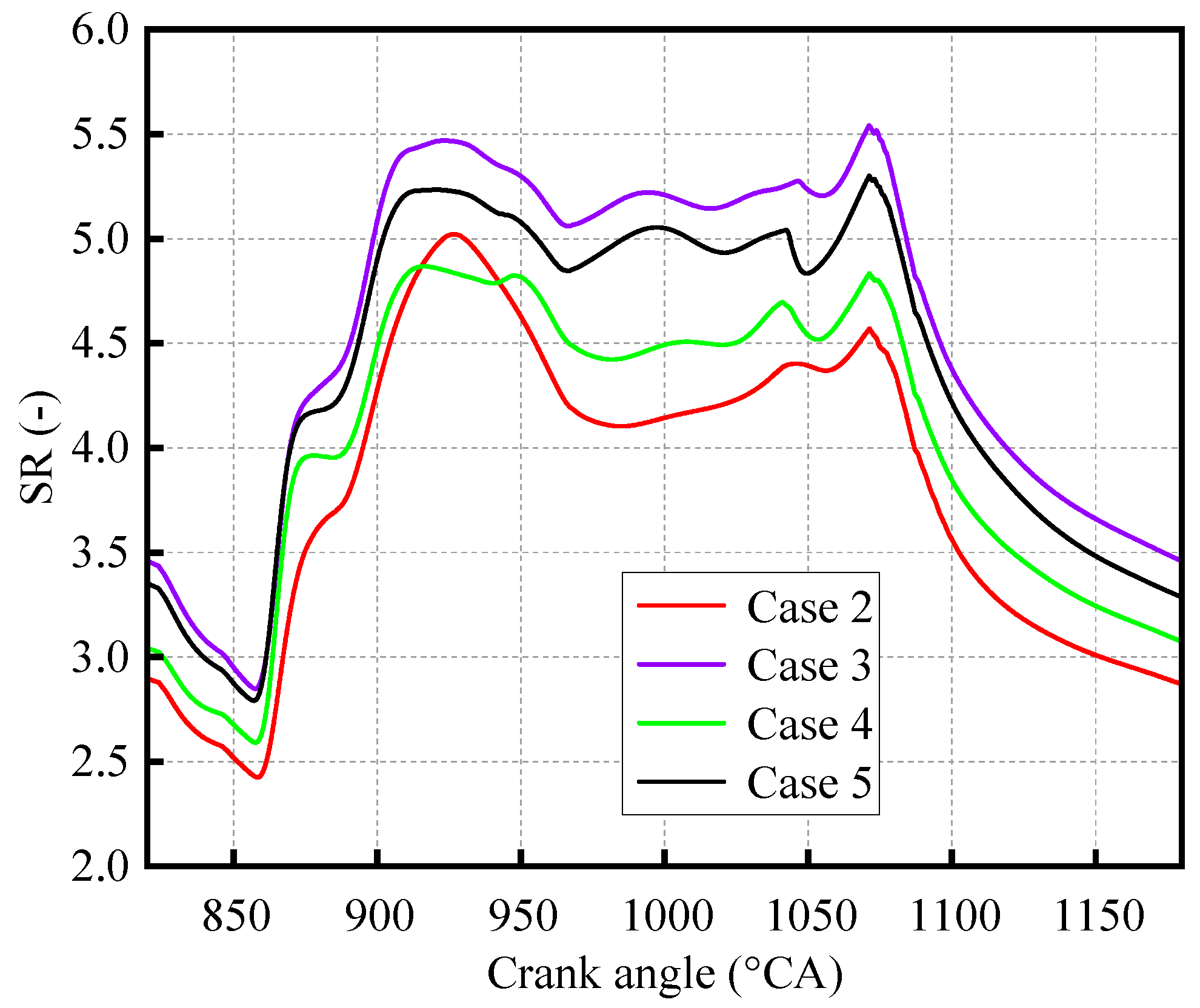
Figure 12 shows the variation curves of the swirl intensity of the four cases in Table 4. The SR of Case 2 and Case 4, which have better scavenging performance, is significantly lower than that of Case 3 and Case 5, which have worse scavenging performance. The SR of Case 2, which has the best scavenging performance, is the lowest, while the SR of Case 3, which has the worst scavenging performance, is the highest. This indicates that the swirl strength under this working condition is too high, and a small swirl strength should be used.
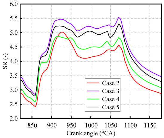
Figure 12.
SR variation curves for different cases.
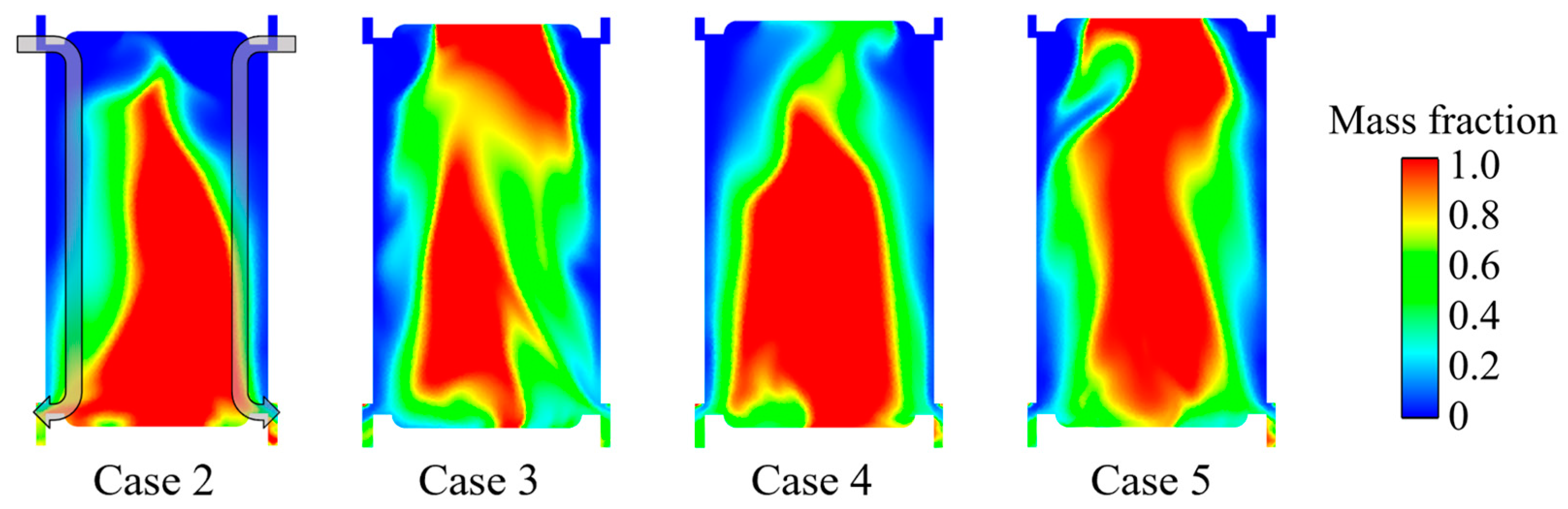
In Figure 13, red represents exhaust gas, blue represents fresh air, and, in Case 2, the arrow represents the flow path of the scavenging airflow. The scavenging paths of the four cases are close to the cylinder wall, and a large amount of exhaust gas appears in the cylinder center, which intuitively shows that the in-cylinder swirl flow is strong under these boundary conditions. Compared to the scavenging cloud image of Case 3, there is less residual exhaust gas in the cylinder center of Case 2, indicating that, for the composite intake ports, the external alignment has stronger air interference than the internal alignment. Air interference reduces swirl intensity and is more conducive to scavenging process at high intake swirl flow. For the dual independent intake ports, the internal alignment has stronger air interference than the external alignment, which is more conducive to improving the scavenging performance under high swirl intensity.
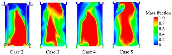
Figure 13.
Exhaust scavenging cloud maps of four cases at 960 °CA.
3.1.2. Combustion Performance Difference
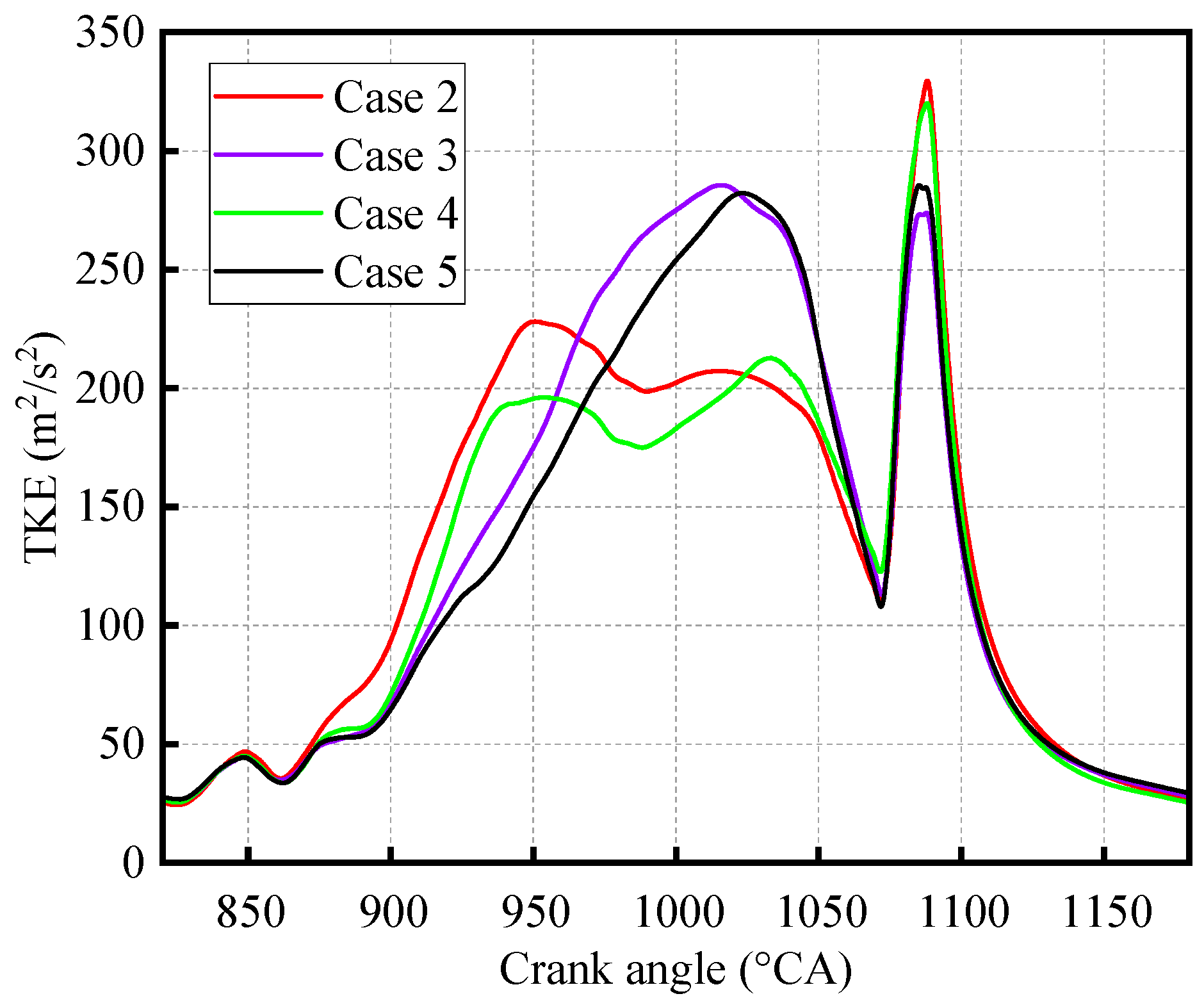
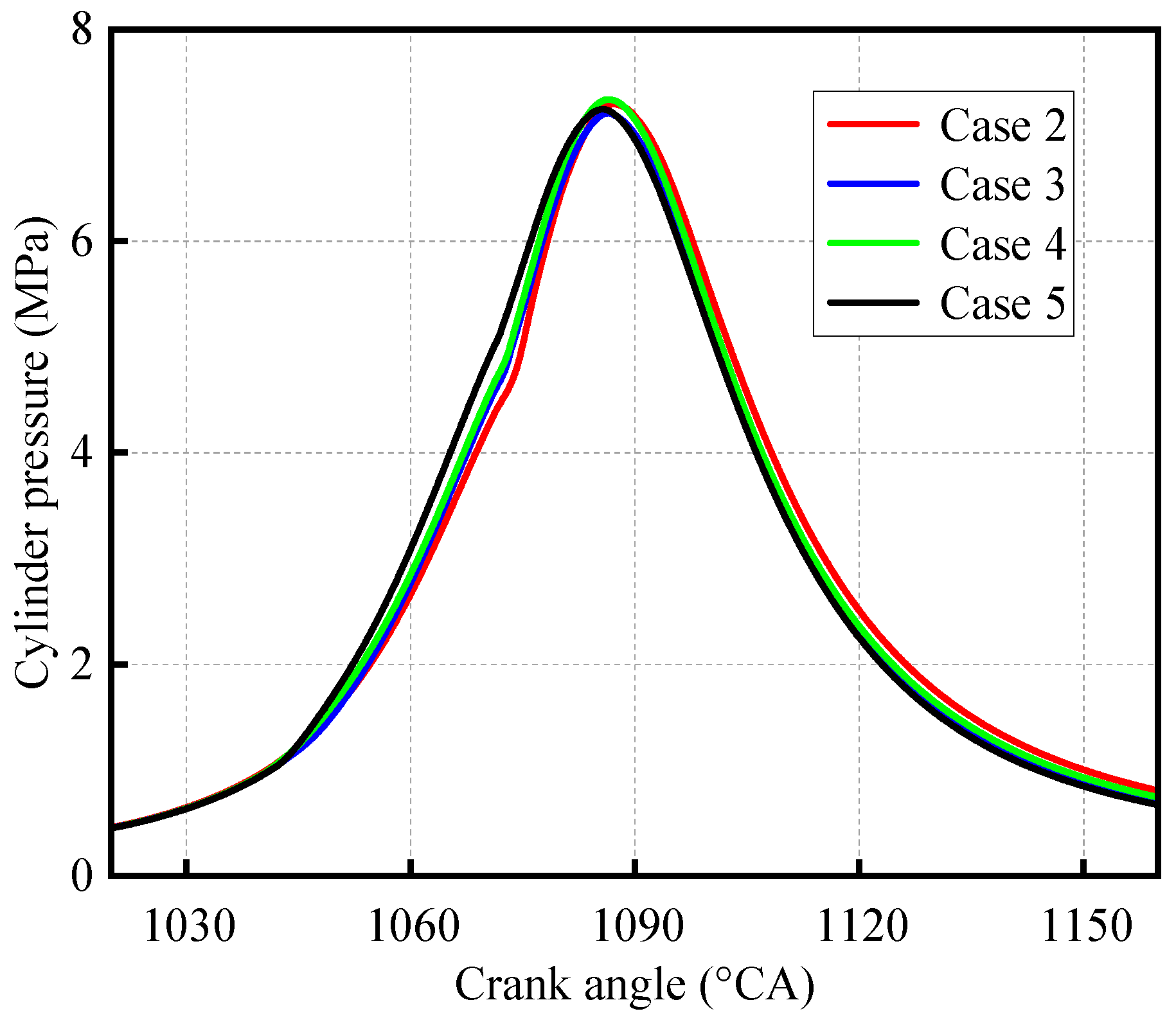
Figure 14 shows the TKE variation curves of the four cases. The TKE source is mainly the in-cylinder swirl flow in the scavenging phase, and the TKE source is mainly the direct injection fuel and the combustion process in the spray combustion phase. Higher TKE values in Case 2 and Case 4 during the combustion phase indicate that these two cases exhibit better combustion performance. In Figure 15, Case 2 and Case 4 also exhibit higher maximum combustion pressures. In addition, the IMEP of Case 2 is 0.767 MPa, the IMEP of Case 3 is 0.662 MPa, the IMEP of Case 4 is 0.680 MPa, and the IMEP of Case 5 is 0.596 MPa, which more intuitively shows that Case 2 and Case 4 have better combustion performance. The performance differences in this section are all caused by the intake structure, indicating that the intake structure significantly impacts the comprehensive performance of the USOP diesel engine.
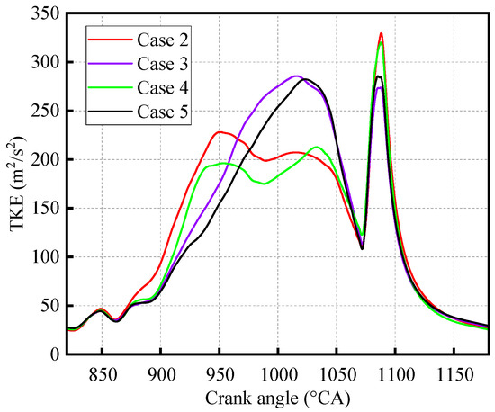
Figure 14.
TKE curves for the four cases.

Figure 15.
Cylinder pressure curves of four cases.
3.2. Structural Characteristics of Different Intake Port Inclination Angles
In order to avoid the adverse effects of too-strong intake swirl and further explore the influence law of the intake structure, this section will explore the comprehensive performance under two intake inclination angles of 20° and 30°. Table 5 shows the scavenging performance of the two intake inclination angles. Under the 30° intake inclination angle, the scavenging performance of the two types of composite structures is basically the same, indicating that the influence is insignificant under this swirl strength. The performance of Case 3 is slightly better than that of Case 2 under the 20° intake inclination angle, which indicates that, under low swirl intensity, reducing airflow interference can maintain higher swirl intensity and help maintain efficient scavenging efficiency.
Table 5.
Scavenging performance of different intake port inclinations.
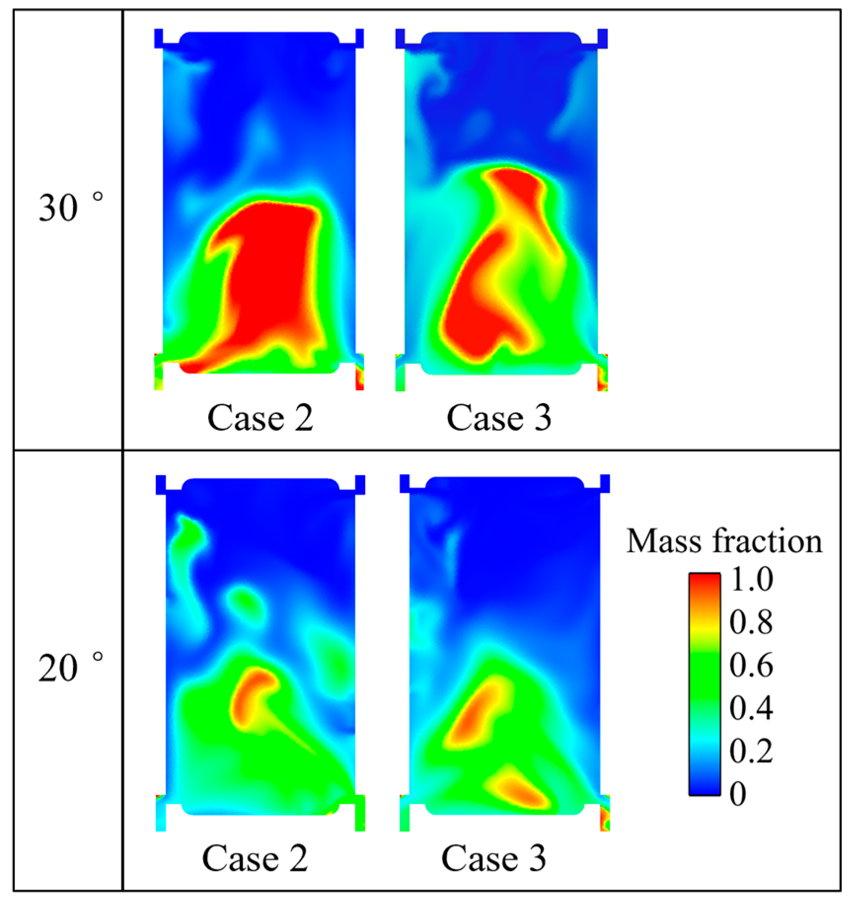
It can be seen from Figure 16 that the scavenging performance of Case 2 and Case 3 is basically the same when the intake inclination angle is 30°. However, when the inclination angle is 20°, the cylinder center in Case 2 shows obvious block-shaped exhaust gas residue, and the scavenging effect of Case 3 is significantly better. Combined with the results in Figure 17, it can be seen that this is due to the lower swirl strength of Case 3 at the 20° inclination angle.

Figure 16.
Exhaust scavenging cloud maps at 960 °CA.
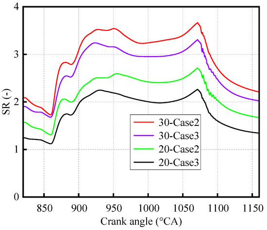
Figure 17.
SR variation curves under various intake port inclination angles.
In Figure 17, 30-Case2 represents Case 2 at a 30° intake inclination angle, 30-Case3 represents Case 3 at a 30° intake inclination angle, 20-Case2 represents Case 2 at a 20° intake inclination angle, and 20-Case3 represents Case 3 at a 20° intake inclination angle. Under the same air supply condition, as the angle is adjusted from 45° to 20°, the swirl strength in the cylinder gradually decreases, and the cases with lower swirl strengths obtain better scavenging performance, but the interference effect of the port changes. When the swirl intensity is too high, the interference effect of the airflow in the external alignment composite intake ports is stronger, which is more conducive to reducing the swirl intensity. In the case of insufficient swirl strength, the interference effect of airflow in the internal alignment composite intake ports is stronger, which will further reduce the swirl strength. The IMEP of 30-Case2 is 0.880 MPa, the IMEP of 30-Case3 is 0.863 MPa, the IMEP of 20-Case2 is 0.880 MPa, and the IMEP of 20-Case3 is 0.905 MPa. In conclusion, the comprehensive performance of a 20° intake inclination angle is better. The 20° intake inclination angle was used as a basic parameter for further study.
3.3. Dual Intake Channels Application Characteristics
3.3.1. Application Characteristics of Swirl Intake Channel Pressure
The composite intake ports of Case 2 and Case 3 in this section are still matched to a single intake channel, while Case 4 and Case 5 will be shown in Figure 1 for dual independent intake ports matched to dual intake channels to realize the independent adjustment of airflow characteristics between different intake ports. Increasing the intake pressure to 1.573 bar for a single intake channel means that all intake port pressures are 1.573 bar. Therefore, the total intake pressure of Case 2 and Case 3 is 1.573 bar. In Case 4 and Case 5, only the swirl intake channel pressure was adjusted to 1.573 bar, and the straight intake channel pressure was maintained at 1.473 bar.
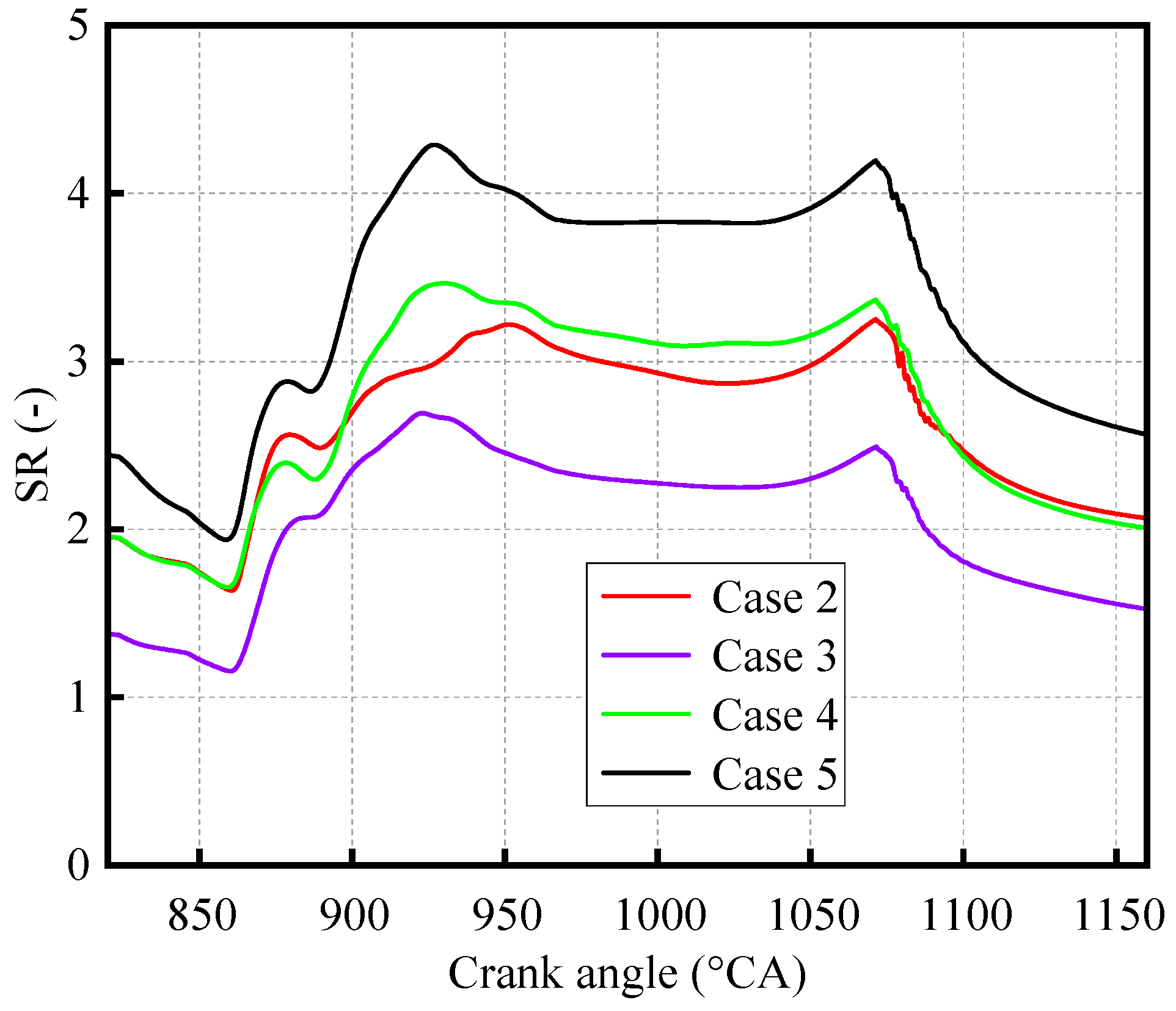
Table 6 shows the comprehensive performance of the four cases at a 1.573 bar intake pressure. Under this condition, there is no significant difference in the performance of the two composite intake ports. The internal alignment structure for dual independent intake ports has better scavenging and combustion performance. Judging from the SR curve in Figure 18, the swirl intensities of Case 2, Case 3, and Case 4 are similar, while the swirl intensity of Case 5 is too high, which is related to the weak airflow interference of the external alignment dual independent intake ports. Therefore, under high swirl intensity, the intake port structure that has strong airflow interference should be used, and the internal alignment structure should be used for dual independent intake ports. In addition, the overall performance of the single intake channel is slightly higher than that of the dual intake channels due to the lower air supply power consumed by the dual intake channels.
Table 6.
Comprehensive performance of four cases at 1.573 bar intake port pressure.
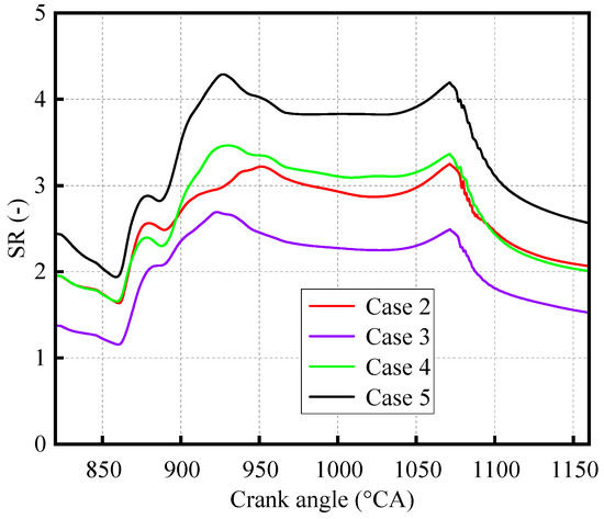
Figure 18.
SR curves at 1.573 bar for four cases.
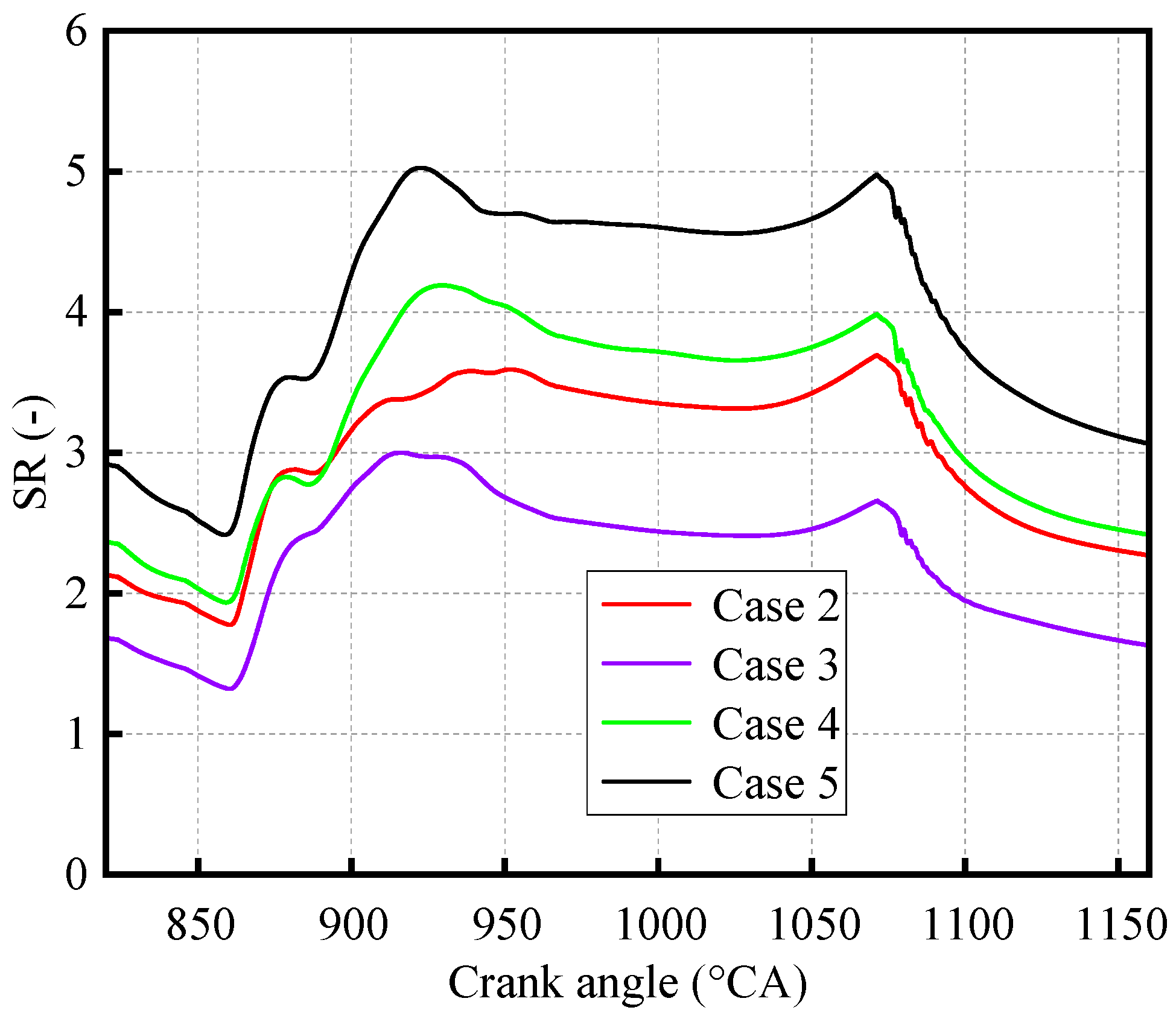
Table 7 shows the comprehensive performance at the 1.673 bar intake pressure. Under this pressure, the influence of the composite intake port structure is still insignificant, and the performance of the internal alignment dual independent intake ports is still better. The performance of Case 5 is basically consistent with that of the 1.573 bar intake pressure. According to Figure 19, the SR value of Case 5 is maintained at about 5, which is because the airflow interference effect of the external alignment in Case 5 is weak, and the adverse effect brought by the further increase of the swirl strength counteracts the favorable effect brought by the increase in intake pressure. In conclusion, excessive intake swirl flow should be avoided, and the intake structure with stronger airflow interference under high intake swirl flow intensity performs better. The internal alignment structure should be used for dual independent intake ports at high swirl strength.
Table 7.
Comprehensive performance of four cases at 1.673 bar intake port pressure.
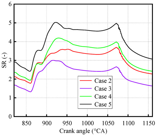
Figure 19.
SR curves at 1.673 bar for four cases.
3.3.2. Dual Intake Channel Energy Efficiency
Case 3 and Case 4 in Table 7 were selected to comprehensively analyze airflow characteristics and air supply power. Figure 20 illustrates the airflow mass into the cylinder from the intake ports in each cycle. The red curve represents the airflow mass in the single intake channel of Case 3. The blue curve represents the airflow mass in the swirl intake channel of Case 4. The green curve represents the airflow mass in the straight intake channel of Case 4. The total air supply mass per cycle in Case 4 is the sum of the blue curve and the green curve. In the figure, both the red and blue curves have obvious negative values at 860 °CA, and the negative value of the red curve is higher than that of the blue curve, indicating that the exhaust gas backflow occurs in the single intake channel and the swirl intake channel of the dual intake channels, and the exhaust gas backflow mass is higher in the single intake channel. However, there is no negative value in the green curve, indicating no exhaust gas backflow in the straight intake channel of the dual intake channels. In conclusion, the exhaust gas backflow mass of the composite intake ports is higher than that of the dual independent intake ports, which has a greater adverse effect on scavenging performance. More importantly, the DR value of the dual independent intake ports of Case 4 in Table 7 is significantly lower than that of the composite intake ports of Case 3, resulting in lower supply air power consumption. This shows that dual independent intake ports can effectively control exhaust gas backflow under lower supply power.
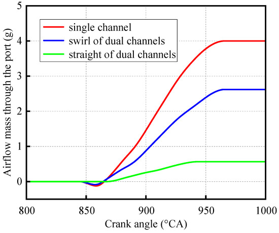
Figure 20.
Airflow mass passing through the intake port.
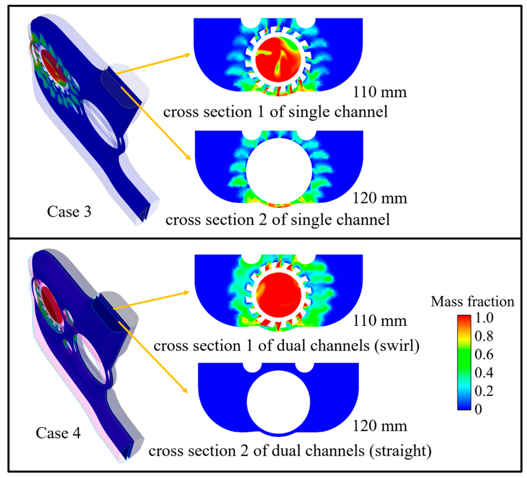
Figure 21 shows the exhaust gas backflow of 860 °CA in Figure 20, and two sections are set in the three-dimensional simulation results to observe the exhaust gas backflow, 110 mm and 120 mm from the inner dead center, respectively. In Case 3, both sections are located in the single intake channel. In Case 4, section 1 is 110 mm in the swirl intake channel, and section 2 is 120 mm in the straight intake channel. The red area in Figure 21 has the highest exhaust gas concentration. In Case 3, there is obvious exhaust gas backflow in both sections. In Case 4, there is only exhaust gas backflow in section 1, while there is no exhaust gas reflux in section 2, which is consistent with the results shown in Figure 20. The three-dimensional results show that the dual intake channels can avoid the diffusion of the backflow exhaust gas in a larger space and reduce the backflow exhaust gas mass.

Figure 21.
The exhaust gas backflow situation of the two intake structures.
When controlling the exhaust gas backflow, the dual intake channels can independently control the pressure in different channels, and only increasing the swirl intake channel pressure reduces the total air supply power. When adjusting the in-cylinder swirl flow intensity, only the swirl intake pressure needs to be changed. The independent adjustment feature of the dual intake channels also reduces the amount of air supply power adjustment, thus reducing unnecessary air supply power losses. Therefore, the dual independent intake ports matching the dual intake channels have better performance and development potential.
4. Conclusions
In this study, the USOP diesel engine simulation model is established, and the key parameters of the simulation model are verified by the cylinder pressure curve and airflow data. The validated model is used to study the characteristics of composite intake ports and dual independent intake ports. The research conclusions are as follows:
- (1)
- For the composite intake ports, under the condition of high swirl intensity, the airflow interference effect of the external alignment composite intake ports is stronger, which can effectively reduce the swirl and improve the DR, SE, CR, and TM. Under the condition of insufficient swirl strength, the airflow interference effect of the internal alignment composite intake ports is stronger, and the external alignment composite intake ports are more conducive to improving the scavenging performance, which further enhances the combustion performance, such as TKE and cylinder pressure. In summary, the external alignment composite intake ports should be used in the design of USOP diesel engines.
- (2)
- For dual independent intake ports, the internal alignment has stronger airflow interference than the external alignment, and the interference trend of the intake structure is uniform. At high swirl intensity, the internal alignment dual independent intake ports should be used to reduce the swirl intensity to improve scavenging performance. At low swirl intensity, the external alignment dual independent intake ports should be used to maintain the swirl intensity to improve scavenging performance.
- (3)
- Under the condition of insufficient air supply, the performance of the external alignment structure of the composite intake ports is significantly better than that of the internal alignment structure, and there is no obvious performance difference between the internal alignment structure and the external alignment structure of the dual independent intake ports. The above results show that when the air supply is insufficient, only the swirl intake ports and the straight intake ports are directly connected, there will be significant performance differences between the internal and external alignment structures, and it also shows that the air interference between the dual independent intake ports is very small in this condition. Under the condition of sufficient air supply, the impact difference between composite intake ports is weakened, and the impact difference between dual independent intake ports is increased.
- (4)
- Dual independent intake ports can effectively control exhaust gas backflow at lower supply power. Dual intake channels can prevent the backflow exhaust gas from spreading, thus reducing the BM. In addition, the dual intake channels can control the intake pressure in different channels, and the total supply power can be reduced by only increasing the swirl intake pressure.
Author Contributions
Y.L.: Conceptualization, Experiment, Validation, Writing—Original Draft; W.W. (Wenxiao Wang): Resources, Methodology, Writing—Review and Editing, Supervision; Z.Z.: Validation, Supervision, Writing—Review and Editing; B.J.: Methodology, Validation, Supervision; W.W. (Wei Wang): Experiment, Validation, Writing—Review and Editing, Supervision, Software; Y.X.: Experiment, Software, Investigation, Datta curation. All authors have read and agreed to the published version of the manuscript.
Funding
This research received no external funding.
Institutional Review Board Statement
Not applicable.
Informed Consent Statement
Informed consent was obtained from all subjects involved in the study.
Data Availability Statement
Data are available upon request.
Conflicts of Interest
The authors declare no conflict of interest.
References
- Drallmeier, J.; Hofmann, H.; Middleton, R.; Siegel, J.; Stefanopoulou, A.; Salvi, A. Work Extraction Efficiency in a Series Hybrid Opposed Piston Engine; SAE Paper 2021-01-1242; SAE: Warrendale, PN, USA, 2021. [Google Scholar]
- Herold, R.; Wahl, M.; Regner, G.; Lemke, J.; Foster, D.E. Thermodynamic Benefits of Opposed-Piston Two-Stroke Engines; SAE Paper 2011-01-2216; SAE: Warrendale, PN, USA, 2011. [Google Scholar] [CrossRef]
- Milojević, S.; Glišović, J.; Savić, S.; Bošković, G.; Bukvić, M.; Stojanović, B. Particulate Matter Emission and Air Pollution Reduction by Applying Variable Systems in Tribologically Optimized Diesel Engines for Vehicles in Road Traffic. Atmosphere 2024, 15, 184. [Google Scholar] [CrossRef]
- Naik, S.; Johnson, D.; Fromm, L.; Koszewnik, J.; Redon, F.; Regner, G.; Abani, N. Achieving Bharat Stage VI Emissions Regulations While Improving Fuel Economy with the Opposed-Piston Engine. SAE Int. J. Engines 2017, 10, 17–26. [Google Scholar] [CrossRef]
- Salvi, A.; Redon, F.; Youngren, D.; Fromm, L. Low CO2, Ultralow NOx Heavy Duty Diesel Engine: Experimental Results; SAE Technical Paper 2022-01-0426; SAE: Warrendale, PN, USA, 2022. [Google Scholar]
- Redon, F.; Kalebjian, C.; Kessler, J.; Rakovec, N.; Headley, J.; Regner, G.; Koszewnik, J. Meeting Stringent 2025 Emissions and Fuel Efficiency Regulations with an Opposed-Piston, Light-Duty Diesel Engine; SAE Paper 2014-01-1187; SAE: Warrendale, PN, USA, 2014. [Google Scholar]
- Regner, G.; Herold, R.E.; Wahl, M.H.; Dion, E.; Redon, F.; Johnson, D.; Callahan, B.J.; McIntyre, S. The Achates Power Opposed-Piston Two-Stroke Engine: Performance and Emissions Results in a Medium-Duty Application. SAE Int. J. Engines 2011, 4, 2726–2735. [Google Scholar] [CrossRef]
- Abani, N.; Chiang, M.; Thomas, I.; Nagar, N.; Zermeno, R.; Regner, G. Developing a 55% BTE Commercial Heavy-Duty Opposed-Piston Engine without a Waste Heat Recovery System; SAE Technical Paper 2017-01-0638; SAE: Warrendale, PN, USA, 2017. [Google Scholar]
- Huo, M.; Huang, Y.; Hofbauer, P. Piston Design Impact on the Scavenging and Combustion in an Opposed-Piston, Opposed-Cylinder (OPOC) Two-Stroke Engine; SAE Technical Paper 2015-01-1269; SAE: Warrendale, PN, USA, 2015. [Google Scholar]
- Guo, C.D.; Zuo, Z.X.; Feng, H.; Jia, B.; Roskilly, T. Review of recent advances of free-piston internal combustion engine linear generator. Appl. Energy 2020, 269, 115084. [Google Scholar] [CrossRef]
- Liu, S.; Xu, Z.; Chen, L.; Liu, L. Comparison of an opposed-piston free-piston engine using single and dual channel uniflow scavenging. Appl. Therm. Eng. 2022, 201, 117813. [Google Scholar] [CrossRef]
- Serrano, J.R.; García, A.; Monsalve-Serrano, J.; Martínez-Boggio, S. High efficiency two stroke opposed piston engine for plug-in hybrid electric vehicle applications: Evaluation under homologation and real driving conditions. Appl. Energy 2021, 282, 116078. [Google Scholar] [CrossRef]
- Serrano, J.R.; Arnau, F.J.; Bares, P.; Gomez-Vilanova, A.; Garrido-Requena, J.; Luna-Blanca, M.J.; Contreras-Anguita, F.J. Analysis of a novel concept of 2-stroke rod-less opposed pistons engine (2S-ROPE): Testing, modelling, and forward potential. Appl. Energy 2021, 282, 116135. [Google Scholar] [CrossRef]
- Turner, J.W.G.; Head, R.A.; Wijetunge, R.; Chang, J.; Engineer, N.; Blundell, D.W.; Burke, P. Analysis of different uniflow scavenging options for a medium-duty 2-stroke engine for a US light-truck application. J. Eng. Gas. Turbine Power 2020, 142, 1–13. [Google Scholar] [CrossRef]
- Wu, Y.; Wang, Y.; Zhen, X.; Guan, S.; Wang, J. Three-dimensional CFD (computational fluid dynamics) analysis of scavenging process in a two-stroke freepiston engine. Energy 2014, 68, 167–173. [Google Scholar] [CrossRef]
- Zhou, L.; Li, H.; Chen, Z.; Zhao, Z.; Zhang, F. Numerical Simulation and Optimization for Combustion of an Opposed Piston Two-Stroke Engine for Unmanned Aerial Vehicle (UAV); SAE Technical Paper 2020-01-0782; SAE: Warrendale, PN, USA, 2020. [Google Scholar]
- Changming, H.; Sichuan, X. Transient Gas Exchange Simulation and Uniflow Scavenging Analysis for a Unique Opposed Piston Diesel Engine; SAE Technical Paper 2016-01-1087; SAE: Warrendale, PN, USA, 2016. [Google Scholar] [CrossRef]
- Mattarelli, E.; Rinaldini, C.; Savioli, T.; Cantore, G.; Warey, A.; Potter, M.; Gopalakrishnan, V.; Balestrino, S. Scavenge Ports Ooptimization of a 2-Stroke Opposed Piston Diesel Engine; SAE Technical Paper 2017-24-0167; SAE: Warrendale, PN, USA, 2017. [Google Scholar]
- O’Donnell, P.C.; Gandolfo, J.; Gainey, B.; Vorwerk, E.; Prucka, R.; Filipi, Z.; Lawler, B.; Hessel, R.; Kokjohn, S.; Huo, M.; et al. Effects of Port Angle on Scavenging of an Opposed Piston Two-Stroke Engine; SAE Technical Paper 2022-01-0590; SAE: Warrendale, PN, USA, 2022. [Google Scholar] [CrossRef]
- Wang, W.; Liang, Y.; Zuo, Z.; Jia, B.; Wang, W. Effects of multitype intake structures on combustion performance of different opposed-piston engines. Appl. Therm. Eng. 2023, 235, 121438. [Google Scholar] [CrossRef]
- Richards, K.J.; Senecal, P.K.; Pomraning, E. Converge Theory Manual; Convergent Sciences Inc.: Madison, WI, USA, 2018; Available online: http://www.convergecfd.com (accessed on 23 August 2024).
- Shirvani, S.; Shirvani, S.; Shamekhi, A.H. Effects of Injection Parameters and Injection Strategy on Emissions and Performance of a Two-Stroke Opposed-Piston Diesel Engine; SAE Technical Paper 2020-01-5064; SAE: Warrendale, PN, USA, 2020. [Google Scholar] [CrossRef]
- O’Donnell, P.C.; Gainey, B.; Vorwerk, E.; Prucka, R.; Lawler, B.; Huo, M.; Salvi, A. An Investigation into the Effects of Swirl on the Performance and Emissions of an Opposed-Piston Two-Stroke Engine Using Large Eddy Simulations; SAE Technical Paper 2022-01-1039; SAE: Warrendale, PN, USA, 2022. [Google Scholar] [CrossRef]
- Wang, W.; Liang, Y.; Zuo, Z.; Jia, B.; Wang, W. Study on the influence principle and application law of intake wall thickness on uniflow scavenging opposed-piston engine. Energy 2024, 291, 130271. [Google Scholar] [CrossRef]
- Han, Z.Y.; Reitz, R.D. Turbulence modeling of internal combustion engines using RNG k-ε models. Combust. Sci. Technol. 1995, 106, 267–295. [Google Scholar] [CrossRef]
- Golovitchev, V.I. Mechanisms (Combustion Chemistry). Available online: http://www.tfd.chalmers.se/~valeri/MECH.html (accessed on 23 August 2024).
- Aggarwal, S.; Awomolo, O.; Akber, K. Ignition characteristics of heptane-hydrogen and heptane-methane fuel blends at elevated pressures. Int. J. Hydrogen Energy 2011, 36, 15392–15402. [Google Scholar] [CrossRef]
- Senecal, P.; Pomraning, E.; Richards, K. Multi-Dimensional Modeling of Direct-Injection Diesel Spray Liquid Length and Flame Lift-Off Length Using CFD and Parallel Detailed Chemistry; SAE Technical Paper 2003–01–1043; SAE: Warrendale, PN, USA, 2003. [Google Scholar] [CrossRef]
- Som, S.; Ramirez, A.I.; Longman, D.E.; Aggarwal, S.K. Effect of nozzle orifice geometry on spray, combustion, and emission characteristics under diesel engine conditions. Fuel 2011, 90, 1267–1276. [Google Scholar] [CrossRef]
- Fu, X.; Aggarwal, S.K. Two-stage ignition and NTC phenomenon in diesel engines. Fuel 2015, 144, 188–196. [Google Scholar] [CrossRef]
- Han, Z.; Reitz, R. A temperature wall function formulation for variable-density turbulent flows with application to engine convective heat transfer modeling. Int. J. Heat. Mass. Transf. 1997, 40, 613–625. [Google Scholar] [CrossRef]
- Schmidt, D.P.; Rutland, C.J. A New Droplet Collision Algorithm. J. Comput. Phys. 2000, 164, 62–80. [Google Scholar] [CrossRef]
- O’Rourke, P.J.; Amsden, A. A Spray/Wall Interaction Submodel for the KIVA-3 Wall Film Model. SAE Trans. 2000, 109, 281–298. [Google Scholar]
- Beale, J.C.; Reitz, R.D. Modeling spray atomization with the Kelvin-Helmholtz/Rayleigh-Taylor hybrid model. At. Sprays 1999, 9, 623–650. [Google Scholar]
- Yang, W.; Li, X.-R.; Kang, Y.-N.; Zuo, H.; Liu, F.-S. Evaluating the scavenging process by the scavenging curve of an opposed-piston, two-stroke (op2s) diesel engine. Appl. Therm. Eng. 2019, 147, 336–346. [Google Scholar] [CrossRef]
- J604_199506; Engine Terminology and Nomenclature-General. SAE IC Powertrain Steering Committee: Warrendale, PN, USA, 1995.
- Liu, Y.; Zhang, F.; Zhao, Z.; Dong, Y.; Ma, F.; Zhang, S. Study on the synthetic scavenging model validation method of opposed-piston two-stroke diesel engine. Appl. Therm. Eng. 2016, 104, 184–192. [Google Scholar] [CrossRef]


Disclaimer/Publisher’s Note: The statements, opinions and data contained in all publications are solely those of the individual author(s) and contributor(s) and not of MDPI and/or the editor(s). MDPI and/or the editor(s) disclaim responsibility for any injury to people or property resulting from any ideas, methods, instructions or products referred to in the content. |
© 2024 by the authors. Licensee MDPI, Basel, Switzerland. This article is an open access article distributed under the terms and conditions of the Creative Commons Attribution (CC BY) license (https://creativecommons.org/licenses/by/4.0/).