
A Review of the Factors Influencing Surface Roughness in Machining and Their Impact on Sustainability


Abstract
:1. Introduction
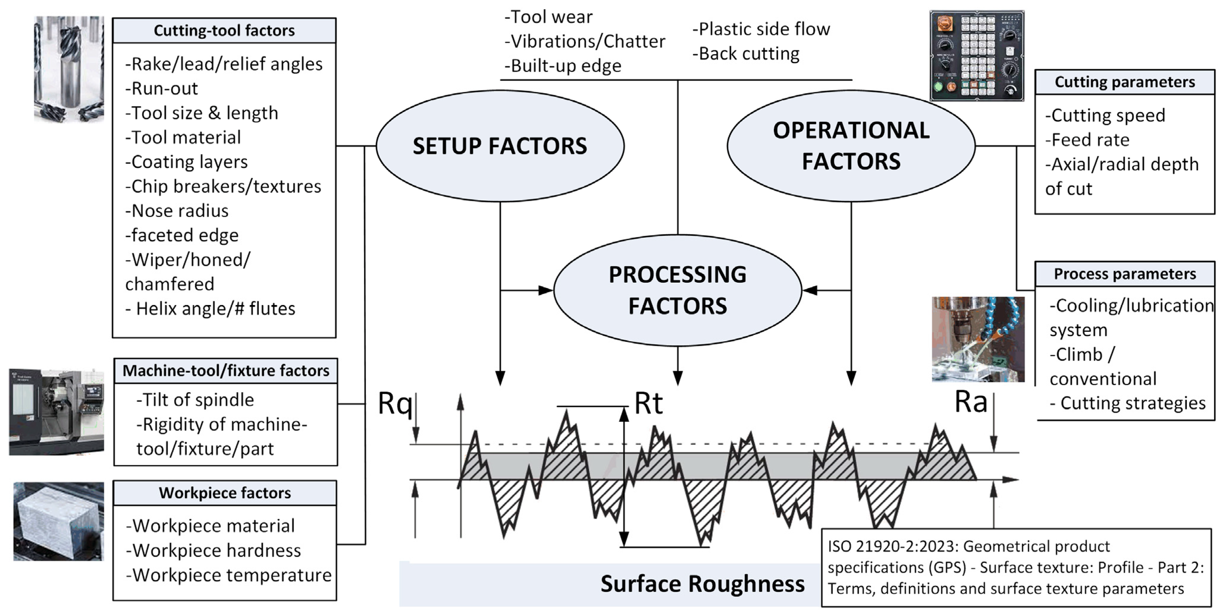
2. Classification of Factors
3. Review of Factors Related to Surface Roughness
3.1. Setup Factors
3.1.1. Cutting Tool Factors
- Tool geometry
- o
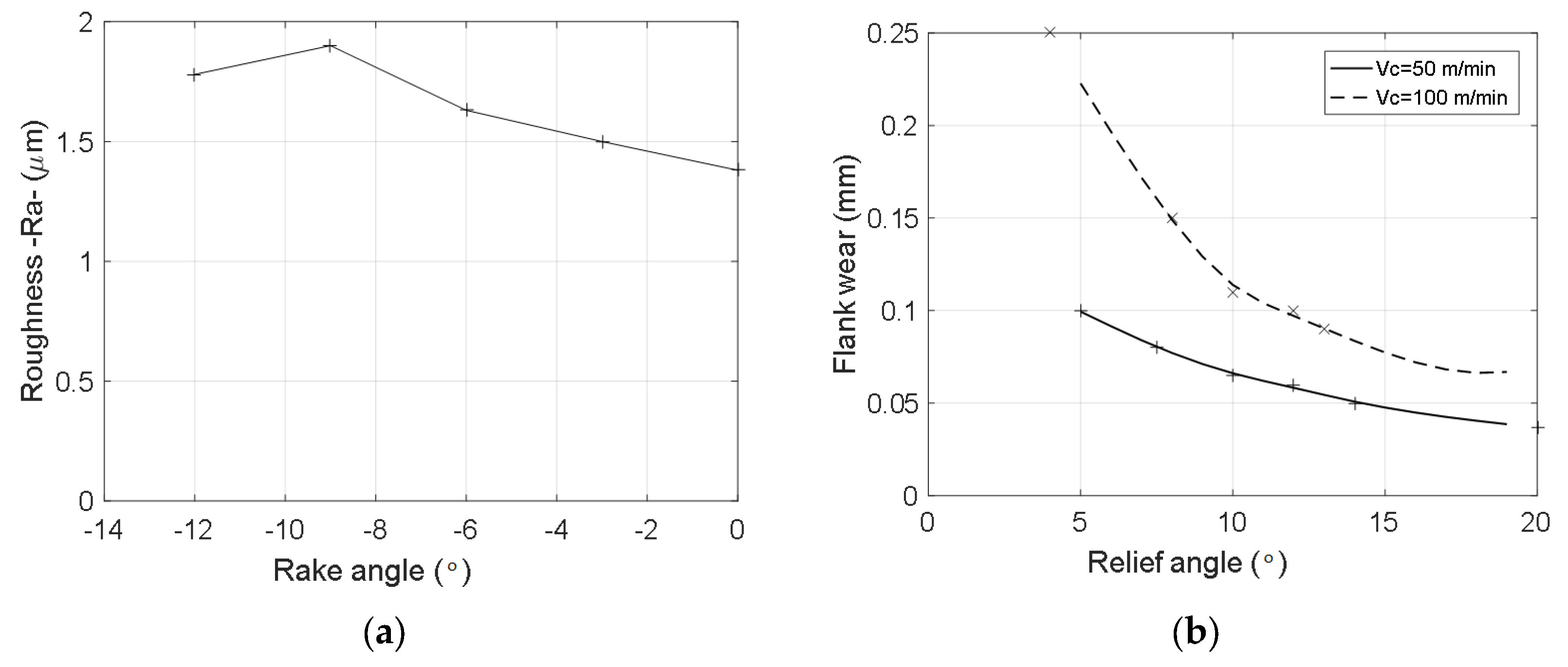
- Rake angle: In general, the use of positive rake angles in machining tends to reduce the cutting pressure, which avoids problems related to workpiece/cutting tool deflection and vibrations. It also prevents adhesion by reducing the built-up edge phenomenon, and thus, positive rake angles tend to produce a better surface roughness [34]. On the contrary, negative rake angles increase the cutting-edge strength but increase cutting forces and make it easy for the workpiece material to adhere to the cutting tool, increasing the surface roughness [7]. For instance, Adesta et al. [35] reported a trend of higher roughness values when increasing the negative value of rake angles when turning medium-carbon steel with cermet tools (Figure 2a).
- o
- Lead angle: When a larger lead angle (smaller entering angle) is applied, the load is spread over a greater length of the edge, creating a smoother cutting action. Since the load is reduced, cutting with larger lead angles can help reduce vibration possibilities, improving the surface roughness [34]. Furthermore, lead angles define the axial and radial components of cutting tools, which will impact tool/workpiece deflections [34].
- o
- Relief angle: The relief angle provides a gap between the insert and the workpiece to avoid rubbing after shearing the material and makes the cutting edge move along the workpiece easily [36]. The relief angle mainly influences the tool wear rate, which will indirectly influence the surface roughness. In general, it is considered that the surface roughness increases as the relief angle becomes close to 0°. Figure 2b shows the influence and evolution of flank wear according to the relief angle when turning AISI 4340 alloy steel in [36] after a cutting time of 20 min, which may have a subsequent impact on the surface roughness. In a recent work, Knápek et al. [37] also showed the influence of the relief angle on the surface roughness and delamination in machining carbon fiber composite boards. Smaller relief angles produce higher wear rates that generate delamination and higher surface roughness values.
- o
- Tool overhang: Tool overhang is directly related to vibrations that negatively impact surface roughness. Chang and Lu [38] showed that the average roughness at both the feeding and axial directions increases due to the increase in the overhang length due to the reduction in the rigidity of the tool. Some authors have studied how to locate the optimum range of tool overhang to minimize tool vibrations [39] and studied the dependence of tool overhang on both surface roughness and tool wear [40].
- o
- Radial and axial run-out: One of the main factors that affects the surface finish in milling operations is the deviation in the location of the cutting tool teeth, especially in indexable cutting tools (Figure 3). The run-out refers to small deviations in the relative positions of the different inserts or cutting tool teeth that compose the tool, mainly due to the manufacturing tolerances or inaccurate assembly in the cutting body when inserts are replaced [41]. Baek et al. [42] showed the influence of run-out in milling operations in AISI 1041 steels and presented a surface roughness model considering the run-out effect to optimize the feed rate to obtain a maximum material removal rate. Krüger and Denkena [43] defined the relationships between cutting forces for a given run-out tool and the surface roughness generated in end mill operations. They presented and experimentally validated a model-based approach to identify the actual tool run-out and surface roughness from measuring cutting forces. Schmitz et al. [44] presented a model to explain the relationship between surface roughness generation and run-out in 6061-T6 aluminum alloys. The authors showed that, due to the presence of run-out, new regions of instability related to chatter occur if the harmonics of the run-out frequency reach the dominant natural frequency of the system.
- o
- Helix angle and flutes: In end milling operations, the helix angle and flute number may have significant impacts on the surface roughness. Sur et al. [45] compared the performance in the peripheral milling of Ti-6Al-4V alloys with fixed and variable helix tools and showed that large helix angles performed best. Chen et al. [46] studied the effect of different tool helix angles in tilt side milling of Al 6061 thin-walled plates. Their experimental results showed that the helix angle had a high impact on the surface roughness, varying from 1–2 µm for a 10° helix angle to less than 1 µm for 40–50° helix angles. On the other hand, the number of flutes is also an important factor, since these channels in the tool allow the chips from the cutting zone to be removed. More flutes mean higher removal rates but less efficient chip evacuation, which may produce excessive heat or clogging that can affect the surface roughness. For instance, Danyan et al. [47] showed that end milling operations in Ti-6Al-4V with three flute tools performed slightly better in terms of the surface roughness than four flute tools. Similarly, Çelik et al. [48] showed that when end milling of glass fiber reinforced plastic composites with cemented carbide tools, the use of two flutes resulted in a reduction of 50% in surface roughness with respect to the same tool with four flutes.
- Insert geometry:
- o
- Insert shape: The shape of the insert may be important since it is related to the vibration tendency during machining. Due to the small nose angle, rhombic or triangular designs may present less vibration tendency, which may improve surface generation. On the other hand, geometries with a large point angle, such as round or square inserts, present a stronger cutting edge, but they need more machine power, and thus, there is a higher tendency to vibrate, which may increase the surface roughness [34].
- o
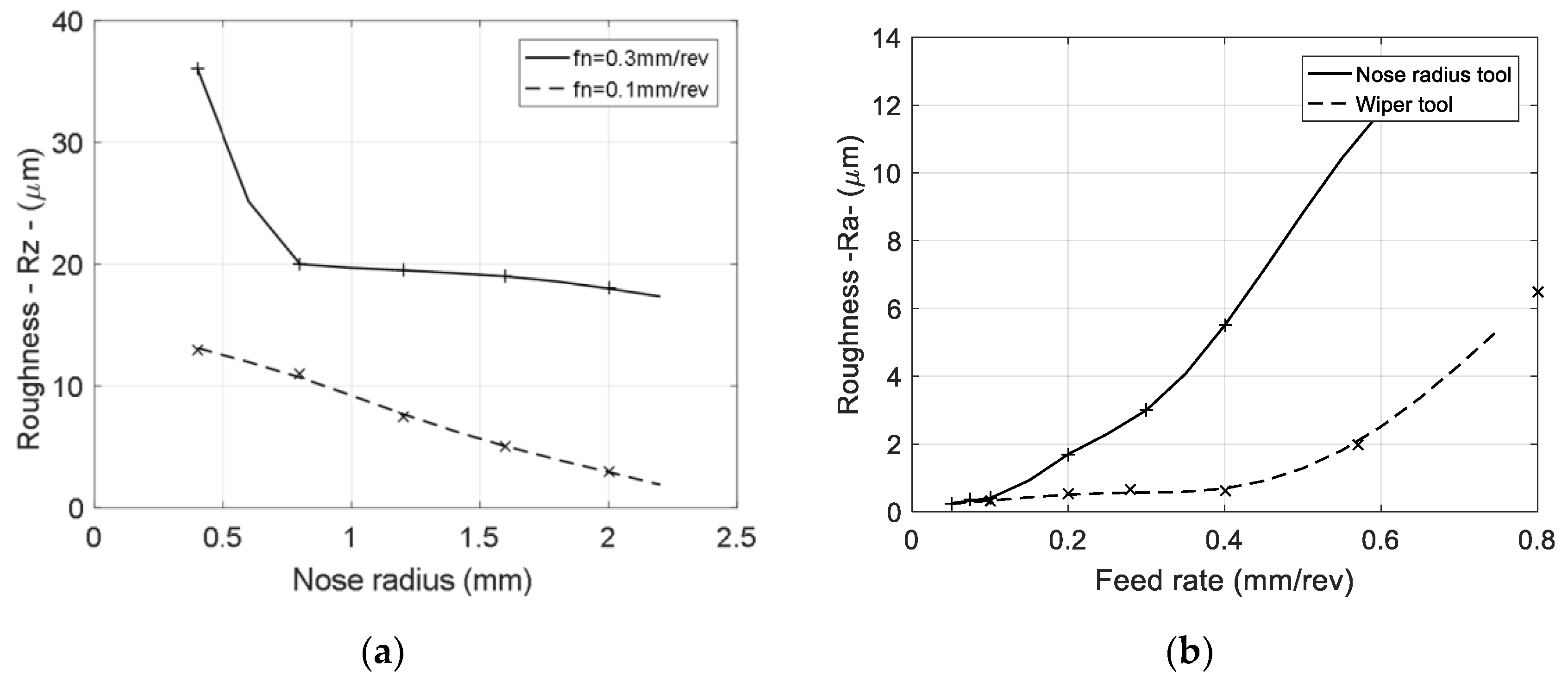
- Corner configuration: The corner configuration heavily influences the strength of the cutting edge and surface finish. An insert with a nose radius is best in roughing applications where the surface finish is not critical. The radius encourages a longer tool life since heat from the machining operation dissipates across a greater surface area [34]. A big nose radius improves the surface roughness and cutting edge strength, but an excessively large radius may produce vibrations and chattering [36]. Shah et al. [49] experimentally showed that in turning operations of Ti-6Al-4V, tool nose variations ranging from 0.4 mm to 1.2 mm had a higher effect on the surface roughness that changed based on the feed rate or cutting speed. Deflection is also a primary concern limiting the size of the nose radius, since an increase in the nose radius increases radial cutting forces. In finishing operations, cutters with corner chamfered inserts or wiper inserts are commonly preferred. Chang and Fuh [50] studied different tool geometries under different side cutting edge angles, nose radii, side rake angles and chamfer angles in turning operations of pure aluminum and carbon steels. In the experimentation, the authors found that specific chamfered edge tools have the advantage of a limited chip contact length within the tool face, the cutting shear area, cutting forces and temperature decrease and it helps to reduce the built-up edge formation, improving the surface roughness. Wiper inserts can produce finer finishes than corner chamfer inserts at higher feed rates due to the special nose design with a long land. In fact, this geometry can reduce the surface roughness by a factor of two or more [51,52], and the degree of improvement increases with the feed rate [3]. However, if large cutters are applied with several wiper inserts, the resulting finish depends significantly on the run-out errors of the cutter. Wipers are mainly used when short chips are produced, such as in machining cast iron or brass. In materials such as steel, chip flow may be difficult, which may produce large tangential and axial forces and, eventually, may generate chatter [3,34]. Figure 4 shows the effects of the nose radius and wiper tools on the surface roughness, adapted from [36,52].
- o
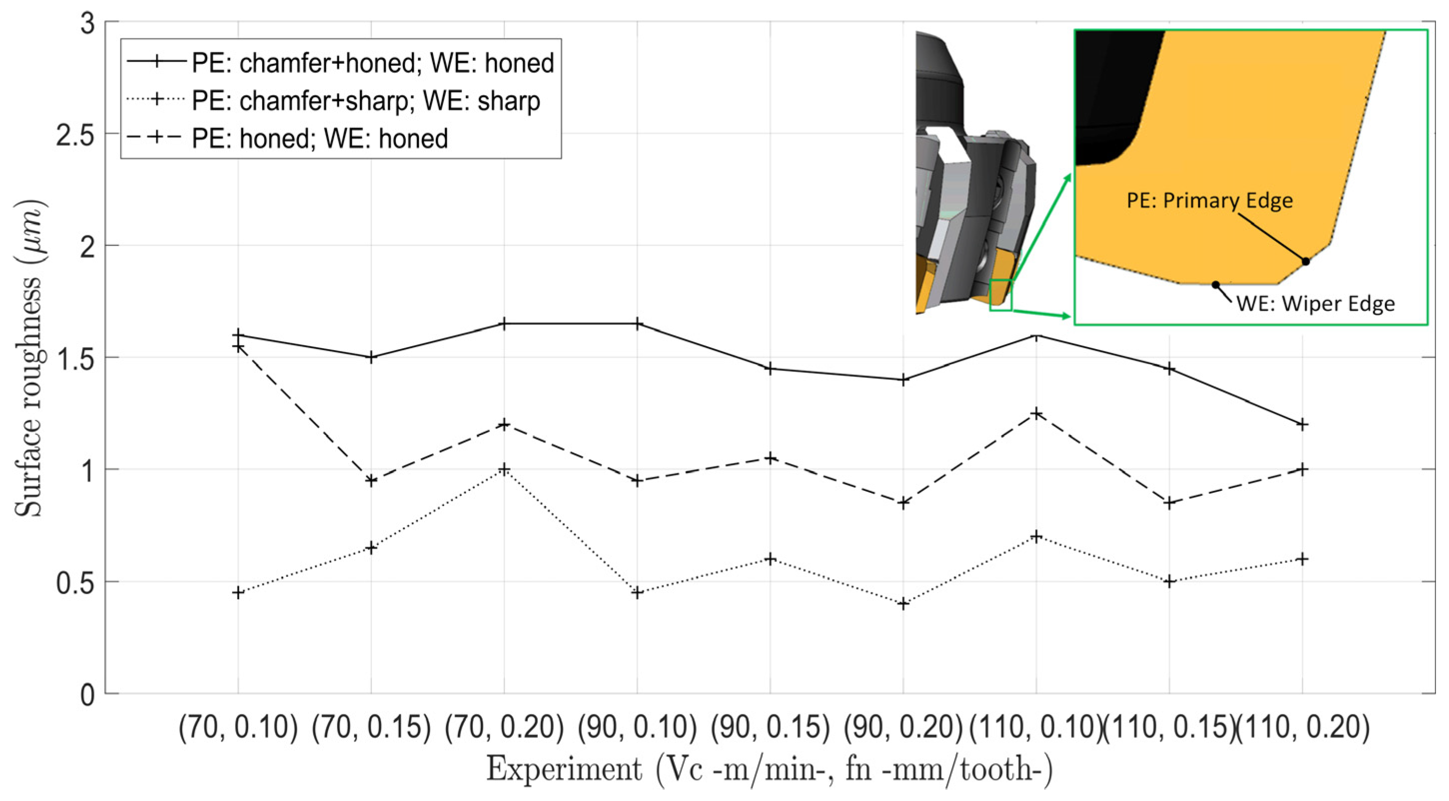
- Edge preparation: Unlike solid tools, where sharp edges are commonly found, indexable tools for both turning and milling operations may present different edge preparations such as hones (honed radius, waterfall and variable honed radius), chamfers and negative lands (similar to chamfered edges but with smaller angles), as well as combinations of these three [53] (Figure 5). It is well known that edge preparation has a significant influence on the tool life, surface finish and surface integrity of the machined part [54]. Chamfered edges and negative lands provide an effective negative angle to the cutting action to provide a stronger edge geometry, which makes the insert less prone to premature breakage. Increasing the edge preparation width increases the cutting resistance, but vibrations may occur, which may have a negative impact on the surface roughness. In general, large edge hone tools produce higher surface roughness values than small edge hone tools or sharper tools [55]. However, honing is necessary to increase the cutting edge strength, even though the sharpness decreases. When the undeformed chip thickness is small, the cutting edge has a large impact on the process stability and produces a higher surface roughness value [56]. Özel et al. [57] studied the effects of cutting edge preparation, workpiece hardness, feed rate and cutting speed on the surface roughness and resultant forces in the finished hard turning of AISI H13 steel. In their experimentation, the authors found out that honed edge geometry with a honed radius of 10.5 ± 4.0 μm resulted in a better surface roughness than that obtained with tools with a chamfered edge of 20°. Zhao et al. [58] tested three different tools of CBN with honed radii of 20, 30 and 40 μm in hard turning AISI 52100 steels, and the results showed that the edge radius of 30 μm presented the lowest roughness in all tests, and the stability of the cutting process was considered as the major reason for this. Childs et al. [59] experimentally showed, in turning operations of aluminum Al 1100 with cemented carbides, that at lower feed rates, the surface roughness value is proportional to the edge radius and independent of the feed value, although it may be limited by the dynamics of the machine tool. Khan et al. [60] analyzed different edge preparations (chamfer and chamfer plus hone) on wiper inserts for hard turning AISI D2 steels. Their results showed that the wiper configuration is seen to be overriding the effect of tool edge preparation, and no significant difference was observed in terms of tool wear and surface roughness between both edge preparations. In a different study, Muthuswamy et al. [61] studied the combination of cutting edge preparation (chamfer, sharp and honed) with wiper features in face milling operations of high-carbon SAE 1070 steels. In their experimental results, cutting inserts with chamfer and sharp preparation on the cutting edge and a sharp wiper edge presented a superior surface finish than other combinations of edge preparation, such as chamfer-honed, chamfer-chamfer and honed-honed preparations (Figure 6).
- o
- Chip breakers and textures: Chip breakers aid in curling the chips and discharge them quickly, improving chip control. If chips can be broken properly, they will not wrap around the workpiece, reducing vibrations and possible workpiece damage. Therefore, chip breakers can enhance the surface finish, reduce the built-up edge and reduce burrs [36]. Gürbüz et al. [62] studied the influence of different chip breaker geometries on surface roughness generation in turning AISI 1050 steels, and they developed an artificial neural network for prediction purposes, showing that a notable difference among five different chip breakers existed. A more novel approach consists of creating textures at the rake face to be used in conjunction with nanofluids in MQL systems, which reduce the tool wear and improve the surface roughness [63]. Readers may refer to [64] for a review about the influence of chip breaking methods in turning.
- Insert/cutter material (material and coating layers): The choice of tool material is very important in order to avoid chip material adhesion, which may produce poor surface finishes. To prevent this phenomenon, a tool grade with low affinity to the workpiece material should be chosen. For machining steel, carbide tools (WC) coated with TiC and TiN are effective. TiC and TiN have a lower solubility to iron than WC, which may help to prevent chip welding. Nalbant et al. [65] reported that increasing the number of coating layers decreases the friction coefficient and parallelly decreases the average surface roughness value of the workpiece. This experimentation was conducted in a CNC lathe using AISI 1030 steels as workpiece materials. The cutting tool materials compared were uncoated WC and WC coated with TiN, TiAlN and AlTiN. The best surface quality was obtained with the TiN-coated multilayered tools—using the CVD method—mainly because of its smaller friction coefficient and thermal conductivity. A similar conclusion was obtained in [66], where uncoated and TiAlN-coated end mills were analyzed in machining Al6061, and the surface roughness was considerably better under the coated tools. However, other researchers did not experimentally find a significant difference, as shown in [67], where micromilling operations in Inconel 718 with different end mill coatings (AlTiN, nACo and TiSiN) were studied. Kumar et al. [68] presented a comparison between Al2O3-coated and uncoated carbide inserts in the hard turning of AISI D2 steel. Besides showing the higher performance of the coated insert versus the uncoated one in terms of tool life and surface roughness, the authors also remarked the high surface quality obtained with Al2O3-coated inserts that would replace costly ceramic or CBN inserts in hard turning. Cakir et al. [69] compared the resultant surface roughness when machining with two carbide inserts with the completely same geometry and substrate but different coating layers, namely one insert with a TiCN underlayer, an intermediate layer of Al2O3 and a TiN outlayer, all deposited by CVD, and another insert with a thin TiAlN layer deposited by PVD. The experimentation was conducted on a CNC lathe and AISI P20 working material, and it was shown that lower surface roughness values are achieved when employing the second insert, which was explained by the higher toughness of the insert and the heat shield effect of the coating. It was suggested that higher toughness may prevent the negative effects of vibrations at lower cutting speeds, whereas the PVD TiAlN coating protects the tool from rapid wear at higher cutting speeds. Darwish [70] compared the performance of ceramic and CBN tools in turning Inconel 718. Under dry conditions and a constant nose radius, the authors showed that there is a 7% improvement in the surface quality at high feed rates and a 10% improvement at low feed rates of ceramic inserts with respect to CBN tools. Chou et al. [71] studied the influence of the CBN content on the surface roughness and tool wear in turning hardened AISI 52100 steel tools. According to their experimental results, tools with low CBN contents produce a better surface roughness value in comparison with tools with higher CBN contents, which was explained by their greater wear resistance and less adhesion. Kumar et al. [72] remarked the importance of tool material on the adhesion tendency of the workpiece material on the rake face, which may produce small welding particles in the insert (i.e., built-up-edge), worsening the surface quality. In general, alumina-based ceramic cutting tools are chemically more stable than high-speed steels and carbides; thus, they present less tendency to adhere to metals during machining, leading to better surface roughness. In addition to all of these aspects, in milling, it has been shown that tool flexibility influences the back cutting phenomenon, since cutting tool deflection lifts the back side of the tool, avoiding the re-cut of the surface [73]. Therefore, carbide end mills that are more rigid than HSS mills tend to more easily present back cutting effects on surface roughness.
3.1.2. Machine Tool/Fixturing Factors
- The tilt of the spindle: In milling, if the cutter is perfectly flat against the workpiece, the finished surface is usually recut by the back side of the cutter due to the axial run-out of tool inserts or slight axial deflection. The spindle can also be slightly tilted towards the back side of the tool, which brings the back side of the cutter below the upper side of the cutter, producing the back cutting phenomenon (Figure 7). Furthermore, after the cut, the edges may carry small chips that may scratch the surface at the back side, and the increased cutter contact may induce chatter [74]. These phenomena subsequently reduce the surface quality and tool’s life. In order to avoid these phenomena, the spindle may be tilted very slightly in the direction of the feed to provide small relief behind the cut [74]. However, too much spindle tilt may be not compensated during cutting and may produce scallops, which are magnified as cutter diameter increases, producing waviness errors that may affect product performance [75]. The effect of the cutter axis tilt was examined by Ryu et al. [76] in order to model surface generation in flat end milling operations together with other cutting tool imperfections, such as radial and axial run-outs, and eccentricity between the tool’s center and spindle rotation center. The experimentation was conducted with a two-fluted tungsten carbon end mill with a 30° helix angle, and the workpiece material used was SS 420J2, a typical mold steel. The results showed that the tilting angle (0.0024° in one of the tools tested) can reduce the peaks in the surface texture. Franco et al. [77] studied the back cutting phenomenon in the face milling of carbon steels with round insert cutting tools. The authors considered axial and radial run-outs and the tool tilt axis and their contribution of front and back cutting to surface roughness. The proposed geometrical model presented good agreement, especially at high feeds, whereas at low speeds, other factors such as vibrations or built-up edge increased model inaccuracy. To monitor the spindle setup tilt and deflection, different methods can be carried out, such as the one proposed by Nguyen et al. [75] based on surface data measured by high-definition metrology.
- Rigidity of machine tool/fixturing/workpiece: The rigidity of the system defined by the machine tool, fixturing and workpiece will influence the stability of the cut and the magnitude of vibrations or chatter generated [34]. Baek et al. [78] developed a dynamic surface roughness model for a face-milling operation of AISI 1041 steels by considering the static and dynamic characteristics of the cutting process. They studied the surface roughness generation of face milling processes and modeled the roughness parameters by considering the run-out effect, the forced vibration occurring in the intermittent cutting process and the static deflection. The authors modeled the face-milling operation as a dynamic system of one degree of freedom while considering the damping and stiffness effects of the cutting tool. The identification of the parameters of the cutting system was obtained by tests of the impact to the tool and workpiece. Childs et al. [59] reported the importance of the dynamics of the machine tool in surface roughness generation. According to their results in the turning operations of aluminum Al 1100 with cemented carbides, at the lowest feeds, Rz becomes independent of the feed and proportional to the edge radius, unless the dynamics of the machine tool intervenes. Additionally, ensuring that the tooth passing frequency and its harmonics do not produce high-frequency responses was shown to be critical to achieve good surface roughness values [79].
3.1.3. Workpiece Factors
- Workpiece materials: The surface roughness may completely differ across different workpiece materials since the particularities of chip formation will depend on material properties. Routara et al. [80] studied the influence of machining parameters on surface quality produced in end milling operations under three different workpiece materials, namely brass, aluminum and mild steel. As expected, the results showed that the response surface models derived for roughness prediction are specific to workpiece materials. Interestingly, the effect of cutting parameters on the roughness parameters was also different for different materials. On the other hand, the use of free-machining additives generally improves machinability since these additives assist in chip formation and lubricate the tool face, reducing adhesion and cutting forces [81]. Recent research works addressed the behavior of composite materials and the influence of process parameters on surface generation and chip formation. They explored mechanisms to mitigate delamination drilling-induced damage, which is detrimental to surface integrity, and explored the use of sustainable fibers with better delamination properties [82].
- Hardness: For the same workpiece material, differences in hardness may contribute notably to surface roughness generation. In general, high hardness values may increase the wear rate and have a negative impact on the surface roughness, whereas low hardness values may produce a built-up edge formation, increasing the surface roughness. Furthermore, milling hard workpiece materials with low entering angles produces high axial cutting forces, which may lead to back cutting and increase surface roughness. Chavoski and Tajdari [83] analyzed the influences of the spindle speed and workpiece hardness on the surface roughness in turning AISI 4140 with CBN tools. From the experimentation, it was observed that, when increasing hardness, there is a decrease in the surface roughness, but when hardness exceeds 55 HRC, the surface roughness increases considerably. Özel et al. [57] reported that a lower workpiece surface hardness results in better surface roughness when turning AISI H3 steels from 50 to 55 HRC. Similarly, Desale and Jahagirdar [84] studied the influences of different workpiece hardness values (from 55 HRC to 62 HRC) on the surface roughness of tool steels, showing a higher roughness value when hardness increases. Chen [85] studied surface roughness values when cutting hardened steel (45–55 HRC) with different CBN tools and stated that the harder the workpiece material, the lower the surface roughness obtained for a given set of operating parameters.
- Workpiece temperature: The workpiece temperature may influence the cutting process since the material becomes softer and easier to cut. Amin et al. [86] studied the influence of workpiece preheating on surface roughness in the end milling of hardened steel D2. The authors showed that preheating the workpiece produces roughness values that are substantially lower in part due to lower tool wear rates, which is mainly explained by the lower hardness in the preheating state. In recent years, to improve the machinability of hard materials, thermal-assisted machining processes have been proposed, resulting in significant reductions in cutting forces and surface roughness. Baek et al. [87] applied high-frequency induction and a laser beam to heat the workpiece before cutting in milling AISI 1045 steels and Inconel 718. Under both heating methods and materials, the cutting forces were reduced, and the surface roughness improved. Parida and Maity [88] showed that heating Inconel 718 alloys to 600 °C before turning resulted in a decrease of around 20% in the surface roughness with respect to the surface roughness obtained without previous heating. Mac et al. [89] studied the milling process of AISI D2 steels while heating the workpiece up to 400 °C using an induction coil. The resulting surface roughness value obtained in these processes was observed to be 0.1 µm at 400 °C, which is much lower than that obtained using the conventional process, which resulted in 0.17 µm. Similarly, Kalantari et al. [90] analyzed laser-assisted turning operations in Ti-6Al-4V, and they also showed a surface roughness improvement at all machining conditions tested.
3.2. Operational Factors
3.2.1. Cutting Parameters
- Cutting speed: In general, it is known that an increase in the cutting speed improves the surface quality since high cutting speeds reduce cutting forces and vibrations, giving a better surface finish [69,91]. Figure 8a shows an example of common surface roughness–cutting speed curves in turning AISI P20 steels, adapted from [69]. Furthermore, the cutting speed is a key parameter to avoid built-up edge formation when machining soft materials, and high cutting speeds are required to reduce the material adhesion [3]. However, other factors may interact, and the final surface roughness may have a different behavior. For instance, Chang and Lu [38] studied a side-milling operation in S45C steels, where they reported that both the feeding direction average roughness and axial direction average roughness increase as the cutting speed increases, which was explained by the increase in the dynamic run-out of the end mill. Nalbant et al. [65] showed that increasing the cutting speed produces a reduction in the average surface roughness for coated cemented carbide cutting tools in turning AISI 1030 steels. However, in the case of uncoated cemented carbide cutting tools, increasing the cutting speed also increases the average surface roughness. In this case, this was explained by the material adhesion, rapid wear-out process and notch wear formations that occur on uncoated cutting tools.
- Feed rate: The feed rate, together with the geometry of the cutting tool nose, is responsible for the geometry of the tooth marks at the workpiece surface. The feed rate is a dominant parameter in machining, and it produces a high increase in surface roughness when it increases [69]. In fact, the feed rate is the main factor used in kinematic models for surface roughness prediction, and in almost all experimental studies, the feed rate is one of the most significant parameters related to surface roughness. When the feed rate decreases, the surface roughness decreases since the feed marks responsible for roughness are less pronounced. However, at very low feeds, other effects such as side flow arise, and the surface roughness is kept constant or even increases [92]. Figure 8b shows an example of the evolution of the surface roughness with respect to the feed rate from the study presented in [92], where the real and ideal roughness values, according to the feed marks due to the feed rate and nose radius, are represented in turning C45 carbon steels.
- Axial depth of cut: The influence of the depth of cut on the surface roughness is usually less important than the feed rate or cutting speed. In fact, some investigations show that it is not a significant factor, while other investigations show the opposite. For instance, Tammineni and Yedula [93] studied face milling operations in Al 1050 aluminum alloys, and they showed that surface roughness depends on the cutting factor feed rate and cutting speeds, but the effect of the depth of cut was observed to be unclear. Ding et al. [94] reported that the axial depth of cut contributes the most to the surface roughness in the hard milling of AISI H13. In their experimentation, an end mill operation was studied, and the increase in the axial depth of cut produced an increase in the cutting forces and in the surface roughness, probably because of the vibrations and deflections of the cutter. However, other researchers have presented different trends. Darwish [70] studied finishing turning operations in Inconel 718 alloys and reported that the depth of cut was the second most important factor affecting the surface roughness after the feed rate, and the effect of the depth of cut was more pronounced at high feed rates, where the surface quality improved when the depth of cut increased.
- Radial depth of cut: In milling, the radial depth of cut is also referred to as stepover or cutting engagement. As a general practice, cutting with the full diameter of the tool should be avoided since the cutting starts with a zero chip thickness, which produces higher surface roughness and higher tool wear rates [34]. Therefore, the radial depth of cut at two-thirds of the tool is commonly recommended in milling operations due to its minimum effect on surface roughness and good material removal rate. However, some researchers have shown the radial depth of cut to have an important role in end milling operations. Jasni and Lajis [91] studied an end mill operation in AISI D2 hardened steels under different cutting speeds and radial depths of cut, and both parameters were equally defined as critical, increasing the surface roughness when the cutting speed decreases or when the radial depth of cut increases, probably due to the increase in cutting forces and tool deflection. A similar trend was observed in [38], where a higher radial depth of cut in side milling operations produced rougher surfaces in S45C steels. More recently, the effect of the relative radial position of the cutter with respect to the workpiece when cutters are bigger than workpiece dimension in flat milling was reported in [95]. This relative position of the cutter produces a predominantly up-milling or down-milling cut, which leads to variations in cutting forces, vibrations and surface roughness. In the experimental results regarding SAE 1045 workpieces, a significant influence existed on surface roughness generation, and the worst surface quality was obtained when the down-milling portion was higher. In ball milling, it is well known that the radial depth of cut is a critical parameter that needs to be set carefully since surface roughness in the transversal direction will be directly related to this value [96] since it acts as the feed rate in that direction.
3.2.2. Process Parameters
- Climb/conventional milling: Climb milling (i.e., down milling) is generally preferred in finishing operations since the cutter starts the cut when the undeformed chip thickness is higher [34]. Unlike climb milling, in conventional milling (i.e., up milling), the cutter starts the cut with a zero chip thickness, causing rubbing or burnishing before the chip can reach its full thickness, which may lead to higher surface roughness [74]. Michalik et al., in their study of thin-walled components from steel C45 [97], recommended the use of the climb milling method to increase the surface quality. Abbas et al. [98] also reported a 22% increase in the surface roughness when conventional milling was used compared to when down milling was used in milling single slots in AISI P20 mold steels.
- Cutting strategies: With the use of Computer-Aided Manufacturing (CAM) systems, many different and complex cutting strategies are easily adopted in conventional machining operations, such as trochoidal, trichoidal, follow-part, zig, zig-zag, plunge, etc. Some investigations have shown that the selected strategy can have a significant impact on the surface roughness. Karkalos et al. [99] analyzed the surface roughness quality of two strategies for slot machining in Al 6082 alloys: conventional and trochoidal. The results showed that the trochoidal strategy provided a superior surface quality. Uzun at al. [100] studied four different strategies in milling AISI X210Cr12 steels, namely trochoidal, follow part, zig and zig-zag, and observed that the best surface roughness value was achieved under the follow part and trochoidal strategies.
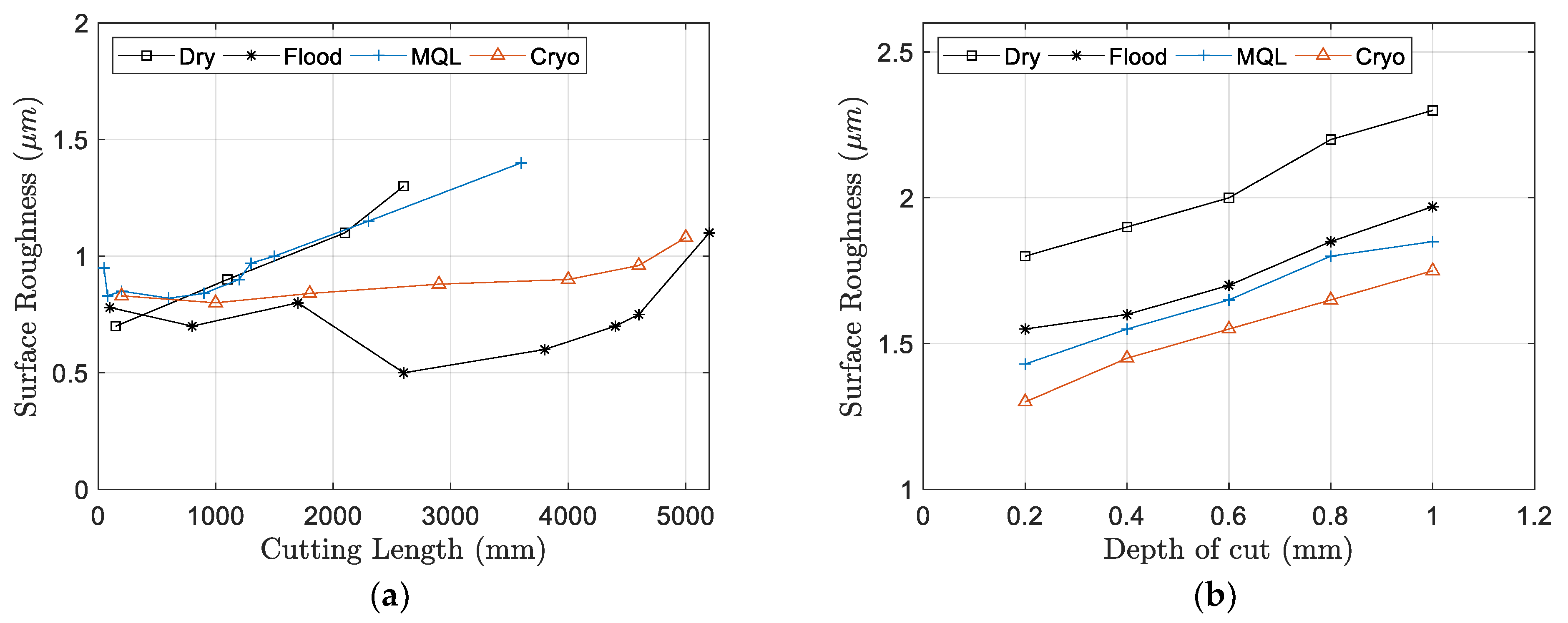
- Coolant: Besides being used to reduce the temperature at the tool–chip interface, cutting fluids are employed in machining operations to reduce the adhesion of the work material to the edges of the tool, improving the surface roughness. Cutting lubricants are particularly effective at low cutting speeds and feed rates where the emergence of the built-up-edge phenomenon may be reduced. From previous works in turning steels [101,102], it can be seen that under dry cutting strategies, the adhesion of the work material to the tool has the highest adhesion rate, increasing the surface roughness. However, the quantity of the adhered material is reduced under flood cooling. Under other coolant strategies, such as minimum quantity lubrication (MQL), the amount of material adhered is commonly higher than that under flood cooling but lower than dry machining [103]. Yan et al. [104] proved that MQL systems, when used in milling 50CrMnMo steels, can reduce tool wear, improve tool life and generate a better surface finish mainly by reducing the friction in the chip–tool and workpiece–tool interfaces, i.e., reducing the adhesion. A maximum quantity of lubricant from which there is no additional reduction in the adhered material has also been identified [103]. Furthermore, MQL requires a correct setup in terms of both the flow rate and nozzle position. Hadad and Sadeghi [102] found that the nozzle position may be critical to MQL performance in turning AISI4140 steel alloys, and lower surface roughness values can be achieved through the supply of oil mist to both the rake and flank faces. Similarly, Duan et al. [105] showed the influence of the nozzle position of MQL systems on the surface roughness of Al 7050 alloys, and Mia et al. [106] experimentally showed the evolution of the lubrication effectivity according to the flow rate applied. Yalçin et al. [107] applied air cooling to reduce adhesion in milling soft materials (annealed AISI 1050, 10 HRC), and they showed that air cooling can be used for the cutting operation for soft steels as an alternative to liquid cooling. Jerold and Kumar [108] studied the use of a CO2 cryogenic coolant to reduce the cutting temperatures to lower and improve the surface roughness. They compared the machining performance of the cryogenic coolant to dry and wet machining in turning AISI 1045 steel. The authors reported that the use of cryogenic cooling reduced cutting temperatures by 5–22% and improved the surface finish by 5–25% compared to when using wet conditions. In [109], dry, flood, MQL and cryogenic cooling were compared in the turning of a 15-5-PH SS alloy, showing a better performance of flood cooling in terms of the surface roughness throughout tool wear evolution (Figure 9a). Sivaiah and Chakradhar [110] compared the same cooling techniques but at different depths of cut in turning 17-4 PH stainless steel, and they showed that surface roughness differences among cooling strategies may reach 75–100%, where the best performance was given by cryogenic cooling systems, whereas the worst performance was seen in dry machining (Figure 9b). In general, oil-based cutting fluids containing fatty acids generate low friction coefficients during cutting at low cutting temperatures, and extreme pressure additives such as chlorine and sulfur compounds are effective at higher cutting temperatures, lowering the friction coefficient, which leads to a reduction in adhesion and better surface roughness [7]. Yin et al. [111] compared the performances of different vegetable oils (cottonseed, palm, castor, soybean and peanut oils) in relation to cutting forces and surface roughness in milling AISI 1045 steels and observed that using palm oil, due to its high viscosity and small contact angle, leads to better surface roughness values. However, fluid penetration between the tool face and the chip may depend on the cutting speed, with the lubrication being more effective at lower speeds. The effect of using solid lubricants, such as graphite and molybdenum disulphide, on hard turning AISI 52100 steel with ceramic inserts was examined in [112]. Solid lubricants, although more difficult to apply, also produce lower surface roughness values in comparison to dry hard turning due to the reduction in material adhesion to the cutting tool. Other papers addressed the poor machinability of composite materials and the use of eco-friendly lubrication systems, like ultrasonic atomization, to reduce carbon emissions [113] and cryogenic cooling conditions [114,115,116].
3.3. Processing Factors
- Built-up edge (BUE): BUE formation may be produced at the tip of the tool, as shown in Figure 10, modifying the tool nose radius and generating higher surface roughness values. The primary cause of a BUE in machining is the adhesion of workpiece material to the tool’s cutting edge during machining operations. The high pressures and temperatures at the cutting interface cause this adhesion. Various factors, including the material being machined, cutting conditions and tool material, can influence the exact mechanisms responsible for the development of a BUE. This phenomenon is particularly important when machining soft materials or using low cutting speeds, although other factors, such as tool geometry and material, cutting conditions or use of lubricants, may interact [117]. Figure 11 shows the influence of different workpiece materials and cutting speeds on the surface roughness. As it can be noticed, the surface roughness increases when the cutting speed decreases due to BUE formation. Furthermore, the BUE also plays an important role in tool wear, which, in turn, is related to surface roughness [7]. In order to reduce BUE formation, it is recommended to increase the cutting speed, use cutting tool grades with less adhesion tendency and use coolants [36]. Increasing the rake angle, using more lightly honed inserts and reducing the undeformed chip thickness are also effective ways of controlling the BUE roughness at relatively low cutting speeds [7].
- Vibrations: Vibrations may have a clear impact on dimensional accuracy, surface roughness, and tool life. Many research works have analyzed the effect of vibrations on surface roughness. Baek et al. [78] studied the generation of surface roughness profiles in face milling operations with AISI 1041 workpiece materials and modeled the process while considering both static and dynamic components. The authors derived a surface roughness model for prediction purposes based on the relative displacement between the workpiece and the cutting tool while considering cutting forces, insert run-out error, insert edge profile and cutting conditions (cutting speed, feed rate and depth of cut). Chang et al. [118] proposed measuring the vibrations from the spindle using a capacitive displacement sensor to predict the surface roughness. The system was modeled as a cantilever beam, and the first mode shape was assumed to be the main vibration that determines surface roughness generation. A simple linear model between the measured surface roughness and the roughness calculated using spindle motion was developed. Similarly, Abouelatta and Mádl [119] reported a correlation between vibrations and surface roughness in turning free-cutting steel, and a surface roughness model based on vibrations and cutting parameters was built for prediction purposes with a good performance. Wang et al. [120] investigated the influence of tool-tip vibration on the surface roughness in ultraprecision single-point diamond turning of copper alloys. Their results showed that the relative tool work displacement during the turning process was mainly due to the high-frequency tool-tip vibration, and it was considered as the dominant factor affecting the roughness of the machined surface. In order to reduce tool vibration and improve the surface roughness, it is necessary to provide sufficiently rigid tooling and workpiece fixtures, and it is especially necessary to limit the overhangs of tools such as boring tools or end mills [57]. Besides using rigid tooling and fixturing devices, vibrations may be reduced using large entering angles, positive rake angles and a low depth of cuts that is larger than the nose radius. The effects of vibrations may be accentuated if the frequency of any component within the machine tool/workpiece system approaches their respective natural frequencies. Under these situations, the interaction between the chip removal and the structure of the machine tool may cause instability in the cutting process with a direct impact on the surface texture. This phenomenon, called chatter, generally occurs under heavy-duty cutting where high depths of cut are the most significant cutting parameters for chatter generation [121]. The cutting process is more stable when the chip width is smaller, and thus, there is a limiting depth of cut where chatter starts to occur. This limiting value depends on many other factors that influence cutting stability. For instance, in high-speed machining, the stability of the cut increases at high spindle speeds, and a higher depth of cuts may be applied without chatter generation. Tool wear is another factor that may result in a drastic change in the dynamics of the cutting process. Tlusty [122] showed that cutting stability may be reached by the damping effect of tool flank wear. Sisson and Kegg [123] found that a high stability at low speeds is caused by the damping generated at the tool–workpiece interface, which is affected by the radius of the tool nose, the clearance angle and the cutting speed. Other factors, such as the preparation of the tool cutting edge; the dynamic characteristics of the structure; the workpiece material, cutting speed and feed; and the geometry of the tool can have important influences on the damping produced by the cutting process [121]. Seguy et al. [124] studied surface roughness generation in thin wall parts due to chattering. Amin et al. [86] showed that in machining hardened steels, preheating workpieces have great potential to lower chatter. Despite the expected negative influence of vibrations, other authors have investigated the possibility of improving the surface roughness if a tool is assisted with high-frequency vibrations [125]. Due to high-frequency vibrations, the tool periodically loses contact with the chip, leading to reductions in machining forces, friction and temperature in the cutting zone. Thinner chips are formed, and there are improvements in cutting stability, surface finish and tool life in comparison to conventional machining. In a previous paper, the authors also reported a surface roughness improvement in turning operations by applying a piezoelectric transducer to excite the system [126].
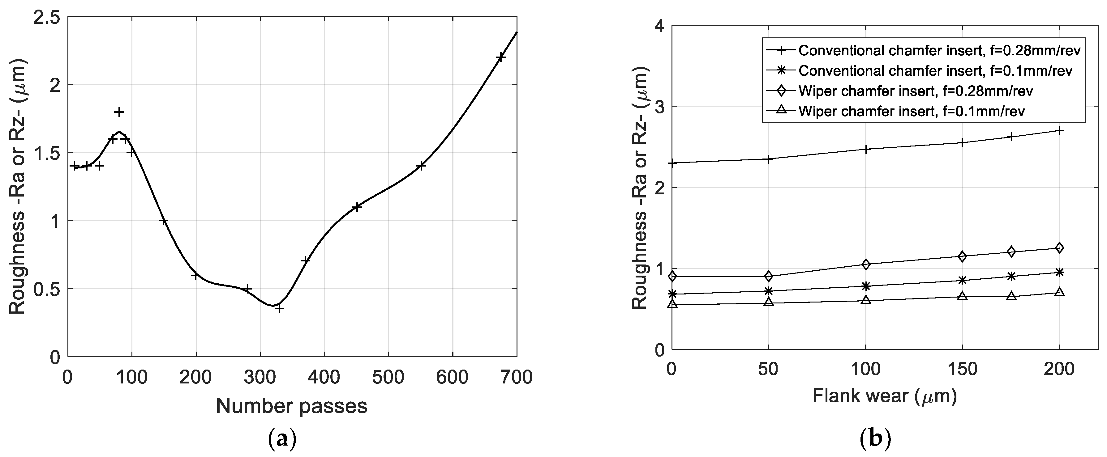
- Tool wear: Many research works have shown that an increase in tool wear produces an increase in surface roughness over cutting time [79,127]. However, many others suggest that at the beginning of the wear-out process, the roughness values exhibit a falling and rising trend with the machining time [85,128] (Figure 12a). Yan et al. [104] observed that high roughness values are generated when the cutting insert is totally new. When the insert starts to be worn, the radius of the tool nose increases and the surface roughness is improved, reducing the teeth marks. Afterwards, a high increase in the tool wear produces irregularities in the nose radius, and the surface roughness rapidly increases. Other studies have shown that the forces and the surface roughness tend to increase as the tool wear increases [60,129] (Figure 12b). Since the cutting temperature is the main factor that influences tool wear progression, coolants are commonly used to reduce the tool wear rate.
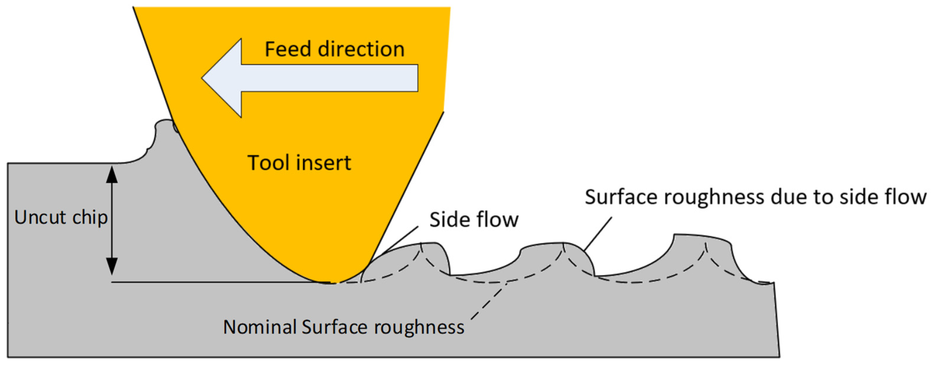
- Plastic side flow: The surface roughness is closely related to the feed rates. However, when low or very low feed rates are applied, the shearing mechanism is replaced by a ploughing mechanism since the chip is not thick enough for removal. Thus, the material is plastically deformed rather than forming a sheared chip, and the accumulation of the deformed material around the tool produces a rougher surface, as shown in Figure 13 [130]. Kishawy et al. [131] studied hard turning operations in 52,100 steels and they showed that more side flow is generated when a higher nose radius is used, increasing the surface roughness. Similarly, Thiele and Melkote [130] proved that a larger cutting edge radius results in more ploughing, and thus, more material is pressed under the tool, which leads to an increased surface roughness. Zong et al. [132] focused their work on single-point diamond turning operations with pure copper workpieces, and they studied surface roughness generation while considering the plastic side flow together with the elastic recovery of the machined material. In their study, they observed that the feed rate, cutting edge radius, corner nose radius and rake angle act as factors that influence surface roughness generation. Experimentally, it has been proven that the quantity of side flow increases with a decrease in the rake angle and with an increase in the depth of cut [133,134]. In general, there is a critical ratio of uncut chip thickness, denoted as hm, to edge radius, re, below which chip formation changes from cutting to ploughing [135]. Experimental and theoretical studies have indicated the critical value of hm/re to be between 0.1 and 0.5, although it depends on the workpiece material and edge rounding of the cutting insert [135].
4. Linking Surface Roughness and Sustainability: Case Studies
4.1. Insert Change Geometry
4.2. Lubricating Change
4.3. Feed Rate Optimization and Early Tool Replacement to Eliminate Secondary Operations
5. Conclusions
- -
- The design of special geometries in cutting inserts. Different edge preparation techniques and textures on rake faces are being actively investigated to reduce the friction coefficients and cutting temperatures. Textures with different sizes and patterns are being machined using a laser or other methods and subsequently tested to improve machining performance.
- -
- Advanced cooling and lubrication systems. Cooling/lubrication systems are bring continuously improved to reduce cutting temperatures and tool wear and limit their impact on surface roughness. Intensive research has been conducted on MQL systems with nanofluids (vegetable oils with small percentages of dispersed nanoparticles, such as carbon nanotubes, molybdenum disulfide or silica nanoparticles), especially in the field of machining difficult-to-cut materials such as titanium or nickel-based alloys.
- -
- Advanced monitoring systems. The implementation of the industrial internet of things (IIOT) facilitates the development of monitoring systems that can apply machine learning or other artificial intelligent approaches to provide optimum machining performances. Under these systems, multi-objective optimization strategies that simultaneously consider diverse performance metrics, including surface roughness, energy consumption, tool wear, and environmental impact, can be deployed.
Author Contributions
Funding
Institutional Review Board Statement
Informed Consent Statement
Data Availability Statement
Conflicts of Interest
References
- ISO 25178-2; Geometrical Product Specifications (GPS)—Surface Texture: Areal Part—2: Terms, Definitions and Surface Texture Parameters. International Organization for Standardization: Geneva, Switzerland, 2023.
- Wang, X.; Feng, C.X. Development of Empirical Models for Surface Roughness Prediction in Finish Turning. Int. J. Adv. Manuf. Technol. 2002, 20, 348–356. [Google Scholar] [CrossRef]
- Stephenson, D.A.; Agapiou, J.S. Metal Cutting Theory and Practice; CRC Press: Boca Raton, FL, USA, 2016. [Google Scholar]
- He, C.L.; Zong, W.J.; Zhang, J.J. Influencing Factors and Theoretical Modeling Methods of Surface Roughness in Turning Process: State-of-the-Art. Int. J. Mach. Tools Manuf. 2018, 129, 15–26. [Google Scholar] [CrossRef]
- Khorasani, A.M.; Yazdi, M.R.S.; Safizadeh, M.S. Analysis of Machining Parameters Effects on Surface Roughness: A Review. Int. J. Comput. Mater. Sci. Surf. Eng. 2012, 5, 68. [Google Scholar] [CrossRef]
- Boothroyd, G. Fundamentals of Metal Machining and Machine Tools; CRC Press: Boca Raton, FL, USA, 1988; Volume 28. [Google Scholar]
- Shaw, M.C. Metal Cutting Principles; Oxford University Press: New York, NY, USA, 2005; Volume 2. [Google Scholar]
- Ghatge, D.; Ramanujam, R. Sustainable Machining: A Review. Mater. Today Proc. 2023, in press. [Google Scholar] [CrossRef]
- Jawahir, I.S.; Schoop, J.; Kaynak, Y.; Balaji, A.K.; Ghosh, R.; Lu, T. Progress Toward Modeling and Optimization of Sustainable Machining Processes. J. Manuf. Sci. Eng. Trans. ASME 2020, 142, 110811. [Google Scholar] [CrossRef]
- Sarikaya, M.; Gupta, M.K.; Tomaz, I.; Danish, M.; Mia, M.; Rubaiee, S.; Jamil, M.; Pimenov, D.Y.; Khanna, N. Cooling Techniques to Improve the Machinability and Sustainability of Light-Weight Alloys: A State-of-the-Art Review. J. Manuf. Process. 2021, 62, 179–201. [Google Scholar] [CrossRef]
- Rajemi, M.F.; Mativenga, P.T.; Aramcharoen, A. Sustainable Machining: Selection of Optimum Turning Conditions Based on Minimum Energy Considerations. J. Clean. Prod. 2010, 18, 1059–1065. [Google Scholar] [CrossRef]
- Pimenov, D.Y.; Mia, M.; Gupta, M.K.; Machado, Á.R.; Pintaude, G.; Unune, D.R.; Khanna, N.; Khan, A.M.; Tomaz, Í.; Wojciechowski, S.; et al. Resource Saving by Optimization and Machining Environments for Sustainable Manufacturing: A Review and Future Prospects. Renew. Sustain. Energy Rev. 2022, 166, 112660. [Google Scholar] [CrossRef]
- Korkmaz, M.E.; Gupta, M.K.; Ross, N.S.; Sivalingam, V. Implementation of Green Cooling/Lubrication Strategies in Metal Cutting Industries: A State of the Art towards Sustainable Future and Challenges. Sustain. Mater. Technol. 2023, 36, e00641. [Google Scholar] [CrossRef]
- Carou, D.; Rubio, E.M.; Davim, J.P. A Note on the Use of the Minimum Quantity Lubrication (MQL) System in Turning. Ind. Lubr. Tribol. 2015, 67, 256–261. [Google Scholar] [CrossRef]
- Davim, J.P.; Sreejith, P.S.; Gomes, R.; Peixoto, C. Experimental Studies on Drilling of Aluminium (AA1050) under Dry, Minimum Quantity of Lubricant, and Flood-Lubricated Conditions. Proc. Inst. Mech. Eng. B J. Eng. Manuf. 2006, 220, 1605–1611. [Google Scholar] [CrossRef]
- Davim, J.P. Surface Integrity in Machining; Springer: Berlin/Heidelberg, Germany, 2010; Volume 1848828742. [Google Scholar]
- Davim, J.P. Sustainable Machining; Springer: Berlin/Heidelberg, Germany, 2017. [Google Scholar]
- Najiha, M.S.; Rahman, M.M.; Yusoff, A.R. Environmental Impacts and Hazards Associated with Metal Working Fluids and Recent Advances in the Sustainable Systems: A Review. Renew. Sustain. Energy Rev. 2016, 60, 1008–1031. [Google Scholar] [CrossRef]
- Goindi, G.S.; Sarkar, P. Dry Machining: A Step towards Sustainable Machining—Challenges and Future Directions. J. Clean. Prod. 2017, 165, 1557–1571. [Google Scholar] [CrossRef]
- Kroll, L.; Blau, P.; Wabner, M.; Frieß, U.; Eulitz, J.; Klärner, M. Lightweight Components for Energy-Efficient Machine Tools. CIRP J. Manuf. Sci. Technol. 2011, 4, 148–160. [Google Scholar] [CrossRef]
- Trampus, V. Energy Saving Tactics for Machine Tools. Manuf. Eng. 2013, 150, 144. [Google Scholar]
- Feng, C.; Huang, S. The Analysis of Key Technologies for Sustainable Machine Tools Design. Appl. Sci. 2020, 10, 731. [Google Scholar] [CrossRef]
- Denkena, B.; Abele, E.; Brecher, C.; Dittrich, M.A.; Kara, S.; Mori, M. Energy Efficient Machine Tools. CIRP Ann. 2020, 69, 646–667. [Google Scholar] [CrossRef]
- Khan, A.M.; He, N.; Jamil, M.; Raza, S.M. Energy Characterization and Energy-Saving Strategies in Sustainable Machining Processes: A State-of-the-Art Review. J. Prod. Syst. Manuf. Sci. 2021, 2, 33. [Google Scholar]
- Masoudi, S.; Esfahani, M.J.; Jafarian, F.; Mirsoleimani, S.A. Comparison the Effect of MQL, Wet and Dry Turning on Surface Topography, Cylindricity Tolerance and Sustainability. Int. J. Precis. Eng. Manuf. Green Technol. 2023, 10, 9–21. [Google Scholar] [CrossRef]
- Mallick, R.; Kumar, R.; Panda, A.; Sahoo, A.K. Current Status of Hard Turning in Manufacturing: Aspects of Cooling Strategy and Sustainability. Lubricants 2023, 11, 108. [Google Scholar] [CrossRef]
- Padhan, S.; Dash, L.; Behera, S.K.; Das, S.R. Modeling and Optimization of Power Consumption for Economic Analysis, Energy-Saving Carbon Footprint Analysis, and Sustainability Assessment in Finish Hard Turning Under Graphene Nanoparticle–Assisted Minimum Quantity Lubrication. Process Integr. Optim. Sustain. 2020, 4, 445–463. [Google Scholar] [CrossRef]
- Dash, L.; Padhan, S.; Das, A.; Das, S.R. Machinability Investigation and Sustainability Assessment in Hard Turning of AISI D3 Steel with Coated Carbide Tool under Nanofluid Minimum Quantity Lubrication-Cooling Condition. Proc. Inst. Mech. Eng. C J. Mech. Eng. Sci. 2021, 235, 6496–6528. [Google Scholar] [CrossRef]
- Gupta, M.K.; Jamil, M.; Wang, X.; Song, Q.; Liu, Z.; Mia, M.; Hegab, H.; Khan, A.M.; Collado, A.G.; Pruncu, C.I.; et al. Performance Evaluation of Vegetable Oil-Based Nano-Cutting Fluids in Environmentally Friendly Machining of Inconel-800 Alloy. Materials 2019, 12, 2792. [Google Scholar] [CrossRef] [PubMed]
- Kadam, G.S.; Pawade, R.S. Surface Integrity and Sustainability Assessment in High-Speed Machining of Inconel 718—An Eco-Friendly Green Approach. J. Clean. Prod. 2017, 147, 273–283. [Google Scholar] [CrossRef]
- Edem, I.F.; Balogun, V.A. Sustainability Analyses of Cutting Edge Radius on Specific Cutting Energy and Surface Finish in Side Milling Processes. Int. J. Adv. Manuf. Technol. 2018, 95, 3381–3391. [Google Scholar] [CrossRef]
- Iqbal, A.; Zhao, G.; Cheok, Q.; He, N.; Nauman, M.M. Sustainable Machining: Tool Life Criterion Based on Work Surface Quality. Processes 2022, 10, 1087. [Google Scholar] [CrossRef]
- Duman, E.; Yapan, Y.F.; Salvi, H.; Sofuoğlu, M.A.; Khanna, N.; Uysal, A. Investigation of Ultrasonic Vibration Assisted Orthogonal Turning under Dry and Minimum Quantity Lubrication Conditions and Performing Sustainability Analyses. J. Clean. Prod. 2024, 434, 140187. [Google Scholar] [CrossRef]
- Sandvick-Coromant. Metal Cutting Technical Guide (D) Milling; Sandvick-Coromant: Sandviken, Sweden, 2008. [Google Scholar]
- Adesta, E.Y.T.; Riza, M.; Hazza, M.; Agusman, D. Rosehan Tool Wear and Surface Finish Investigation in High Speed Turning Using Cermet Insert by Applying Negative Rake Angles. Eur. J. Sci. Res. 2009, 38, 180–188. [Google Scholar]
- Korloy Technical Information. Available online: https://sunsteel.eu/IMG/pdf/catalogue_technique_korloy.pdf (accessed on 9 January 2024).
- Knápek, T.; Dvořáčková, Š.; Váňa, M. The Effect of Clearance Angle on Tool Life, Cutting Forces, Surface Roughness, and Delamination during Carbon-Fiber-Reinforced Plastic Milling. Materials 2023, 16, 5002. [Google Scholar] [CrossRef]
- Chang, C.-K.; Lu, H.S. Study on the Prediction Model of Surface Roughness for Side Milling Operations. Int. J. Adv. Manuf. Technol. 2006, 29, 867–878. [Google Scholar] [CrossRef]
- Mishra, V.; Khan, G.S.; Chattopadhyay, K.D.; Nand, K.; Sarepaka, R.V. Effects of Tool Overhang on Selection of Machining Parameters and Surface Finish during Diamond Turning. Measurement 2014, 55, 353–361. [Google Scholar] [CrossRef]
- Kiyak, M.; Kaner, B.; Sahin, I.; Aldemir, B.; Cakir, O. The Dependence of Tool Overhang on Surface Quality and Tool Wear in the Turning Process. Int. J. Adv. Manuf. Technol. 2010, 51, 431–438. [Google Scholar] [CrossRef]
- Franco, P.; Estrems, M.; Faura, F. Influence of Radial and Axial Runouts on Surface Roughness in Face Milling with Round Insert Cutting Tools. Int. J. Mach. Tools Manuf. 2004, 44, 1555–1565. [Google Scholar] [CrossRef]
- Baek, D.K.; Ko, T.J.; Kim, H.S. Optimization of Feedrate in a Face Milling Operation Using a Surface Roughness Model. Int. J. Mach. Tools Manuf. 2001, 41, 451–462. [Google Scholar] [CrossRef]
- Krüger, M.; Denkena, B. Model-Based Identification of Tool Runout in End Milling and Estimation of Surface Roughness from Measured Cutting Forces. Int. J. Adv. Manuf. Technol. 2013, 65, 1067–1080. [Google Scholar] [CrossRef]
- Schmitz, T.L.; Couey, J.; Marsh, E.; Mauntler, N.; Hughes, D. Runout Effects in Milling: Surface Finish, Surface Location Error, and Stability. Int. J. Mach. Tools Manuf. 2007, 47, 841–851. [Google Scholar] [CrossRef]
- Sur, G.; Motorcu, A.R.; Nohutçu, S. Single and Multi-Objective Optimization for Cutting Force and Surface Roughness in Peripheral Milling of Ti6Al4V Using Fixed and Variable Helix Angle Tools. J. Manuf. Process 2022, 80, 529–545. [Google Scholar] [CrossRef]
- Chen, M.; Liu, G.; Dang, J.; Li, C.; Ming, W. Effects of Tool Helix Angles on Machined Surface Morphology in Tilt Side Milling of Cantilever Thin-Walled Plates. Procedia CIRP 2018, 71, 93–98. [Google Scholar] [CrossRef]
- Daniyan, I.; Tlhabadira, I.; Mpofu, K.; Adeodu, A. Investigating the Geometrical Effects of Cutting Tool on the Surface Roughness of Titanium Alloy (Ti6Al4V) during Milling Operation. Procedia CIRP 2021, 99, 157–164. [Google Scholar] [CrossRef]
- Çelik, Y.; Kılıçkap, E.; Yardımeden, A. Estimate of cutting forces and surface roughness in end milling of glass fiber reinforced plastic composites using fuzzy logic system. Sci. Eng. Compos. Mater. 2013, 21, 435–443. [Google Scholar] [CrossRef]
- Shah, D.; Bhavsar, S. Effect of Tool Nose Radius and Machining Parameters on Cutting Force, Cutting Temperature and Surface Roughness-An Experimental Study of Ti-6Al-4V (ELI). Mater. Today Proc. 2020, 22, 1977–1986. [Google Scholar] [CrossRef]
- Chang, C.S.; Fuh, K.H. An Experimental Study of the Chip Flow of Chamfered Main Cutting Edge Tools. J. Mater. Process. Technol. 1998, 73, 167–178. [Google Scholar] [CrossRef]
- Taha Mohamed Abbas, A. Comparative Assessment of Wiper and Conventional Carbide Inserts on Surface Roughness in the Turning of High Strength Steel. J. Mater. Sci. Res. 2015, 5, 32. [Google Scholar] [CrossRef]
- Grzesik, W.; Wanat, T. Surface Finish Generated in Hard Turning of Quenched Alloy Steel Parts Using Conventional and Wiper Ceramic Inserts. Int. J. Mach. Tools Manuf. 2006, 46, 1988–1995. [Google Scholar] [CrossRef]
- Zhuang, K.; Fu, C.; Weng, J.; Hu, C. Cutting edge microgeometries in metal cutting: A review. Int. J. Adv. Manuf. Technol. 2021, 116, 2045–2092. [Google Scholar] [CrossRef]
- Kumar, S.; Padmakumar, M. An Experimental Study of Applying Various Cutting Edges on Wiper Milling Inserts in Face Milling AISI 1070 Steel. Int. J. Mech. Ind. Eng. 2012, 2, 50–55. [Google Scholar]
- Dogra, M.; Sharma, V.S.; Dureja, J. Effect of Tool Geometry Variation on Finish Turning—A Review. J. Eng. Sci. Technol. Rev. 2011, 4, 1–13. [Google Scholar] [CrossRef]
- Denkena, B.; Biermann, D. Cutting Edge Geometries. CIRP Ann. Manuf. Technol. 2014, 63, 631–653. [Google Scholar] [CrossRef]
- Özel, T.; Hsu, T.K.; Zeren, E. Effects of Cutting Edge Geometry, Workpiece Hardness, Feed Rate and Cutting Speed on Surface Roughness and Forces in Finish Turning of Hardened AISI H13 Steel. Int. J. Adv. Manuf. Technol. 2005, 25, 262–269. [Google Scholar] [CrossRef]
- Zhao, T.; Zhou, J.M.; Bushlya, V.; Ståhl, J.E. Effect of Cutting Edge Radius on Surface Roughness and Tool Wear in Hard Turning of AISI 52100 Steel. Int. J. Adv. Manuf. Technol. 2017, 91, 3611–3618. [Google Scholar] [CrossRef]
- Childs, T.H.C.; Sekiya, K.; Tezuka, R.; Yamane, Y.; Dornfeld, D.; Lee, D.E.; Min, S.; Wright, P.K. Surface Finishes from Turning and Facing with Round Nosed Tools. CIRP Ann. Manuf. Technol. 2008, 57, 89–92. [Google Scholar] [CrossRef]
- Khan, S.A.; Umar, M.; Saleem, M.Q.; Mufti, N.A.; Raza, S.F. Experimental Investigations on Wiper Inserts’ Edge Preparation, Workpiece Hardness and Operating Parameters in Hard Turning of AISI D2 Steel. J. Manuf. Process. 2018, 34, 187–196. [Google Scholar] [CrossRef]
- Muthuswamy, P.; Nagarajan, S.K. Experimental Investigation on the Effect of Different Micro-Geometries on Cutting Edge and Wiper Edge on Surface Roughness and Forces in Face Milling. Lubricants 2021, 9, 102. [Google Scholar] [CrossRef]
- Gürbüz, H.; Sözen, A.; Şeker, U. Modelling of Effects of Various Chip Breaker Forms on Surface Roughness in Turning Operations by Utilizing Artificial Neural Networks. J. Polytech. 2016, 19, 71–83. [Google Scholar]
- Peña-Parás, L.; Maldonado-Cortés, D.; Rodríguez-Villalobos, M.; Romero-Cantú, A.G.; Montemayor, O.E. Enhancing Tool Life, and Reducing Power Consumption and Surface Roughness in Milling Processes by Nanolubricants and Laser Surface Texturing. J. Clean. Prod. 2020, 253, 119836. [Google Scholar] [CrossRef]
- Yılmaz, B.; Karabulut, Ş.; Güllü, A. A Review of the Chip Breaking Methods for Continuous Chips in Turning. J. Manuf. Process 2020, 49, 50–69. [Google Scholar] [CrossRef]
- Nalbant, M.; Gökkaya, H.; Toktaş, I.; Sur, G. The Experimental Investigation of the Effects of Uncoated, PVD- and CVD-Coated Cemented Carbide Inserts and Cutting Parameters on Surface Roughness in CNC Turning and Its Prediction Using Artificial Neural Networks. Robot. Comput. Integr. Manuf. 2009, 25, 211–223. [Google Scholar] [CrossRef]
- Haja Syeddu Masooth, P.; Jayakumar, V.; Bharathiraja, G. Experimental Investigation on Surface Roughness in CNC End Milling Process by Uncoated and TiAlN Coated Carbide End Mill under Dry Conditions. Mater. Today Proc. 2020, 22, 726–736. [Google Scholar] [CrossRef]
- Muhammad, A.; Gupta, M.K.; Mikołajczyk, T.; Pimenov, D.Y.; Giasin, K. Effect of Tool Coating and Cutting Parameters on Surface Roughness and Burr Formation during Micromilling of Inconel 718. Metals 2021, 11, 167. [Google Scholar] [CrossRef]
- Kumar, R.; Sahoo, A.K.; Mishra, P.C.; Das, R.K. Comparative Investigation towards Machinability Improvement in Hard Turning Using Coated and Uncoated Carbide Inserts: Part I Experimental Investigation. Adv. Manuf. 2018, 6, 52–70. [Google Scholar] [CrossRef]
- Cakir, M.C.; Ensarioglu, C.; Demirayak, I. Mathematical Modeling of Surface Roughness for Evaluating the Effects of Cutting Parameters and Coating Material. J. Mater. Process. Technol. 2009, 209, 102–109. [Google Scholar] [CrossRef]
- Darwish, S.M. Impact of the Tool Material and the Cutting Parameters on Surface Roughness of Supermet 718 Nickel Superalloy. J. Mater. Process. Technol. 2000, 97, 10–18. [Google Scholar] [CrossRef]
- Chou, Y.K.; Evans, C.J.; Barash, M.M. Experimental Investigation on CBN Turning of Hardened AISI 52100 Steel. J. Mater. Process. Technol. 2002, 124, 274–283. [Google Scholar] [CrossRef]
- Kumar, A.S.; Durai, A.R.; Sornakumar, T. Wear Behaviour of Alumina Based Ceramic Cutting Tools on Machining Steels. Tribol. Int. 2006, 39, 191–197. [Google Scholar] [CrossRef]
- Melkote, S.N.; Sutherland, J.W.; King, C. The Effect of Tool Flexibility on Back-Cutting in End Milled Surfaces. J. Manuf. Sci. Eng. 1999, 121, 532–537. [Google Scholar] [CrossRef]
- Ingersoll-Cutting-Tools. Technical Information. Better Surface Finishes. M458; Ingersoll-Cutting-Tools: Rockford, IL, USA, 2009. [Google Scholar]
- Nguyen, H.T.; Wang, H.; Hu, S.J. Modeling Cutter Tilt and Cutter-Spindle Stiffness for Machine Condition Monitoring in Face Milling Using High-Definition Surface Metrology. Int. J. Adv. Manuf. Technol. 2014, 70, 1323–1335. [Google Scholar] [CrossRef]
- Ryu, S.H.; Choi, D.K.; Chu, C.N. Roughness and Texture Generation on End Milled Surfaces. Int. J. Mach. Tools Manuf. 2006, 46, 404–412. [Google Scholar] [CrossRef]
- Franco, P.; Estrems, M.; Faura, F. A Study of Back Cutting Surface Finish from Tool Errors and Machine Tool Deviations during Face Milling. Int. J. Mach. Tools Manuf. 2008, 48, 112–123. [Google Scholar] [CrossRef]
- Kyun Baek, D.; Jo Ko, T.; Sool Kim, H. A Dynamic Surface Roughness Model for Face Milling. Precis. Eng. 1997, 20, 171–178. [Google Scholar] [CrossRef]
- De Aguiar, M.M.; Diniz, A.E.; Pederiva, R. Correlating Surface Roughness, Tool Wear and Tool Vibration in the Milling Process of Hardened Steel Using Long Slender Tools. Int. J. Mach. Tools Manuf. 2013, 68, 1–10. [Google Scholar] [CrossRef]
- Routara, B.C.; Bandyopadhyay, A.; Sahoo, P. Roughness Modeling and Optimization in CNC End Milling Using Response Surface Method: Effect of Workpiece Material Variation. Int. J. Adv. Manuf. Technol. 2009, 40, 1166–1180. [Google Scholar] [CrossRef]
- Li, Z.; Wu, D. Effect of Free-Cutting Additives on Machining Characteristics of Austenitic Stainless Steels. J. Mater. Sci. Technol. 2010, 26, 839–844. [Google Scholar] [CrossRef]
- Ismail, S.O.; Dhakal, H.N.; Popov, I.; Beaugrand, J. Comprehensive Study on Machinability of Sustainable and Conventional Fibre Reinforced Polymer Composites. Eng. Sci. Technol. Int. J. 2016, 19, 2043–2052. [Google Scholar] [CrossRef]
- Chavoshi, S.Z.; Tajdari, M. Surface Roughness Modelling in Hard Turning Operation of AISI 4140 Using CBN Cutting Tool. Int. J. Mater. Form. 2010, 3, 233–239. [Google Scholar] [CrossRef]
- Desale, P.S.; Jahagirdar, R.S. Modeling the Effect of Variable Work Piece Hardness on Surface Roughness in an End Milling Using Multiple Regression and Adaptive Neuro Fuzzy Inference System. Int. J. Ind. Eng. Comput. 2014, 5, 265–272. [Google Scholar] [CrossRef]
- Chen, W. Cutting Forces and Surface Finish When Machining Medium Hardness Steel Using CBN Tools. Int. J. Mach. Tools Manuf. 2000, 40, 455–466. [Google Scholar] [CrossRef]
- Amin, A.K.M.N.; Dolah, S.B.; Mahmud, M.B.; Lajis, M.A. Effects of Workpiece Preheating on Surface Roughness, Chatter and Tool Performance during End Milling of Hardened Steel D2. J. Mater. Process. Technol. 2008, 201, 466–470. [Google Scholar] [CrossRef]
- Baek, J.T.; Woo, W.S.; Lee, C.M. A Study on the Machining Characteristics of Induction and Laser-Induction Assisted Machining of AISI 1045 Steel and Inconel 718. J. Manuf. Process. 2018, 34, 513–522. [Google Scholar] [CrossRef]
- Parida, A.K.; Maity, K. Study of Machinability in Heat-Assisted Machining of Nickel-Base Alloy. Measurement 2021, 170, 108682. [Google Scholar] [CrossRef]
- Mac, T.B.; Luyen, T.T.; Nguyen, D.T. Assessment of the Effect of Thermal-Assisted Machining on the Machinability of SKD11 Alloy Steel. Metals 2023, 13, 699. [Google Scholar] [CrossRef]
- Kalantari, O.; Jafarian, F.; Fallah, M.M. Comparative Investigation of Surface Integrity in Laser Assisted and Conventional Machining of Ti-6Al-4 V Alloy. J. Manuf. Process 2021, 62, 90–98. [Google Scholar] [CrossRef]
- Jasni, N.A.H.; Lajis, M.A. Surface Topography in Machining of AISI D2 Hardened Steel. Appl. Mech. Mater. 2013, 315, 660–664. [Google Scholar] [CrossRef]
- Grzesik, W. A Revised Model for Predicting Surface Roughness in Turning. Wear 1996, 194, 143. [Google Scholar] [CrossRef]
- Tammineni, L.; Yedula, H.P.R. Investigation of Influence of Milling Parameters on Surface Roughness and Flatness. Int. J. Adv. Eng. Technol. 2014, 6, 2416. [Google Scholar]
- Ding, T.; Zhang, S.; Wang, Y.; Zhu, X. Empirical Models and Optimal Cutting Parameters for Cutting Forces and Surface Roughness in Hard Milling of AISI H13 Steel. Int. J. Adv. Manuf. Technol. 2010, 51, 45–55. [Google Scholar] [CrossRef]
- Pimenov, D.Y.; Hassui, A.; Wojciechowski, S.; Mia, M.; Magri, A.; Suyama, D.I.; Bustillo, A.; Krolczyk, G.; Gupta, M.K. Effect of the Relative Position of the Face Milling Tool towards the Workpiece on Machined Surface Roughness and Milling Dynamics. Appl. Sci. 2019, 9, 842. [Google Scholar] [CrossRef]
- Buj-Corral, I.; Vivancos-Calvet, J.; Domínguez-Fernández, A. Surface Topography in Ball-End Milling Processes as a Function of Feed per Tooth and Radial Depth of Cut. Int. J. Mach. Tools Manuf. 2012, 53, 151–159. [Google Scholar] [CrossRef]
- Michalik, P.; Zajac, J.; Hatala, M.; Mital, D.; Fecova, V. Monitoring Surface Roughness of Thin-Walled Components from Steel C45 Machining down and up Milling. Measurement 2014, 58, 416–428. [Google Scholar] [CrossRef]
- Abbas, A.T.; Abdelnasser, E.; Naeim, N.; Alqosaibi, K.F.; Al-Bahkali, E.A.; Elkaseer, A. Effect of Milling Strategy on the Surface Quality of AISI P20 Mold Steel. Metals 2024, 14, 48. [Google Scholar] [CrossRef]
- Karkalos, N.E.; Karmiris-Obratański, P.; Kurpiel, S.; Zagórski, K.; Markopoulos, A.P. Investigation on the Surface Quality Obtained during Trochoidal Milling of 6082 Aluminum Alloy. Machines 2021, 9, 75. [Google Scholar] [CrossRef]
- Uzun, M.; Usca, Ü.A.; Kuntoğlu, M.; Gupta, M.K. Influence of Tool Path Strategies on Machining Time, Tool Wear, and Surface Roughness during Milling of AISI X210Cr12 Steel. Int. J. Adv. Manuf. Technol. 2022, 119, 2709–2720. [Google Scholar] [CrossRef]
- Dhar, N.R.; Ahmed, M.T.; Islam, S. An Experimental Investigation on Effect of Minimum Quantity Lubrication in Machining AISI 1040 Steel. Int. J. Mach. Tools Manuf. 2007, 47, 748–753. [Google Scholar] [CrossRef]
- Hadad, M.; Sadeghi, B. Minimum Quantity Lubrication-MQL Turning of AISI 4140 Steel Alloy. J. Clean. Prod. 2013, 54, 332–343. [Google Scholar] [CrossRef]
- Sreejith, P.S. Machining of 6061 Aluminium Alloy with MQL, Dry and Flooded Lubricant Conditions. Mater. Lett. 2008, 62, 276–278. [Google Scholar] [CrossRef]
- Yan, L.; Yuan, S.; Liu, Q. Influence of Minimum Quantity Lubrication Parameters on Tool Wear and Surface Roughness in Milling of Forged Steel. Chin. J. Mech. Eng. 2012, 25, 419–429. [Google Scholar] [CrossRef]
- Duan, Z.; Li, C.; Zhang, Y.; Dong, L.; Bai, X.; Yang, M.; Jia, D.; Li, R.; Cao, H.; Xu, X. Milling Surface Roughness for 7050 Aluminum Alloy Cavity Influenced by Nozzle Position of Nanofluid Minimum Quantity Lubrication. Chin. J. Aeronaut. 2021, 34, 33–53. [Google Scholar] [CrossRef]
- Mia, M.; Al Bashir, M.; Khan, M.A.; Dhar, N.R. Optimization of MQL Flow Rate for Minimum Cutting Force and Surface Roughness in End Milling of Hardened Steel (HRC 40). Int. J. Adv. Manuf. Technol. 2017, 89, 675–690. [Google Scholar] [CrossRef]
- Yalçin, B.; Özgür, A.E.; Koru, M. The Effects of Various Cooling Strategies on Surface Roughness and Tool Wear during Soft Materials Milling. Mater. Des. 2009, 30, 896–899. [Google Scholar] [CrossRef]
- Dilip Jerold, B.; Pradeep Kumar, M. Experimental Investigation of Turning AISI 1045 Steel Using Cryogenic Carbon Dioxide as the Cutting Fluid. J. Manuf. Process. 2011, 13, 113–119. [Google Scholar] [CrossRef]
- Khanna, N.; Shah, P. Chetan Comparative Analysis of Dry, Flood, MQL and Cryogenic CO2 Techniques during the Machining of 15-5-PH SS Alloy. Tribol. Int. 2020, 146, 106196. [Google Scholar] [CrossRef]
- Sivaiah, P.; Chakradhar, D. Effect of Cryogenic Coolant on Turning Performance Characteristics during Machining of 17-4 PH Stainless Steel: A Comparison with MQL, Wet, Dry Machining. CIRP J. Manuf. Sci. Technol. 2018, 21, 86–96. [Google Scholar] [CrossRef]
- Yin, Q.; Li, C.; Dong, L.; Bai, X.; Zhang, Y.; Yang, M.; Jia, D.; Li, R.; Liu, Z. Effects of Physicochemical Properties of Different Base Oils on Friction Coefficient and Surface Roughness in MQL Milling AISI 1045. Int. J. Precis. Eng. Manuf. Green Technol. 2021, 8, 1629–1647. [Google Scholar] [CrossRef]
- Dilbag, S.; Rao, P.V. Performance Improvement of Hard Turning with Solid Lubricants. Int. J. Adv. Manuf. Technol. 2008, 38, 529–535. [Google Scholar] [CrossRef]
- Zhang, X.; Li, A.; Chen, J.; Ma, M.; Ding, P.; Huang, X.; Yu, T.; Zhao, J. Sustainability-Driven Optimization of Ultrasonic Atomization-Assisted Micro Milling Process with Ceramic Matrix Composite. Sustain. Mater. Technol. 2022, 33, e00465. [Google Scholar] [CrossRef]
- Sivalingam, V.; Zhou, Q.; Manickajothi, G.; Ross, N.S.; Sun, J.; Gupta, M.K.; Korkmaz, M.E.; Nagamalai, T. Understanding the Machining Characteristics of Al6082 Hybrid Metal Matrix Composites Milled under Cryogenic Cooling Conditions. Int. J. Adv. Manuf. Technol. 2023, 129, 3387–3402. [Google Scholar] [CrossRef]
- Agrawal, C.; Khanna, N.; Pimenov, D.Y.; Wojciechowski, S.; Giasin, K.; Sarıkaya, M.; Yıldırım, Ç.V.; Jamil, M. Experimental Investigation on the Effect of Dry and Multi-Jet Cryogenic Cooling on the Machinability and Hole Accuracy of CFRP Composites. J. Mater. Res. Technol. 2022, 18, 1772–1783. [Google Scholar] [CrossRef]
- Khanna, N.; Suri, N.M.; Shah, P.; Hegab, H.; Mia, M. Cryogenic Turning of In-House Cast Magnesium Based MMCs: A Comprehensive Investigation. J. Mater. Res. Technol. 2020, 9, 7628–7643. [Google Scholar] [CrossRef]
- Atlati, S.; Haddag, B.; Nouari, M.; Moufki, A. Effect of the Local Friction and Contact Nature on the Built-Up Edge Formation Process in Machining Ductile Metals. Tribol. Int. 2015, 90, 217–227. [Google Scholar] [CrossRef]
- Chang, H.K.; Kim, J.H.; Kim, I.H.; Jang, D.Y.; Han, D.C. In-Process Surface Roughness Prediction Using Displacement Signals from Spindle Motion. Int. J. Mach. Tools Manuf. 2007, 47, 1021–1026. [Google Scholar] [CrossRef]
- Abouelatta, O.B.; Mádl, J. Surface Roughness Prediction Based on Cutting Parameters and Tool Vibrations in Turning Operations. J. Mater. Process. Technol. 2001, 118, 269–277. [Google Scholar] [CrossRef]
- Wang, H.; To, S.; Chan, C.Y. Investigation on the Influence of Tool-Tip Vibration on Surface Roughness and Its Representative Measurement in Ultra-Precision Diamond Turning. Int. J. Mach. Tools Manuf. 2013, 69, 20–29. [Google Scholar] [CrossRef]
- Siddhpura, M.; Paurobally, R. A Review of Chatter Vibration Research in Turning. Int. J. Mach. Tools Manuf. 2012, 61, 27–47. [Google Scholar] [CrossRef]
- Tlusty, J. Manufacturing Processes and Equipment; Prentice Hall: Upper Saddle River, NJ, USA, 1999. [Google Scholar]
- Sisson, T.R.; Kegg, R.L. An Explanation of Low-Speed Chatter Effects. J. Eng. Ind. 1969, 91, 951–958. [Google Scholar] [CrossRef]
- Seguy, S.; Dessein, G.; Arnaud, L. Surface Roughness Variation of Thin Wall Milling, Related to Modal Interactions. Int. J. Mach. Tools Manuf. 2008, 48, 261–274. [Google Scholar] [CrossRef]
- Ostasevicius, V.; Gaidys, R.; Dauksevicius, R.; Mikuckyte, S. Study of Vibration Milling for Improving Surface Finish of Difficult-to-Cut Materials. Stroj. Vestn./J. Mech. Eng. 2013, 59, 351–357. [Google Scholar] [CrossRef]
- Ostasevicius, V.; Gaidys, R.; Rimkeviciene, J.; Dauksevicius, R. An Approach Based on Tool Mode Control for Surface Roughness Reduction in High-Frequency Vibration Cutting. J. Sound Vib. 2010, 329, 4866–4879. [Google Scholar] [CrossRef]
- Grzesik, W. Influence of Tool Wear on Surface Roughness in Hard Turning Using Differently Shaped Ceramic Tools. Wear 2008, 265, 327–335. [Google Scholar] [CrossRef]
- Gu, J.; Barber, G.C.; Jiang, Q.; Tung, S. Surface Roughness Model for Worn Inserts of Face Milling: Part I—Factors That Affect Arithmetic Surface Roughness. Tribol. Trans. 2001, 44, 47–52. [Google Scholar] [CrossRef]
- Siller, H.R.; Vila, C.; Rodríguez, C.A.; Abellán, J.V. Study of Face Milling of Hardened AISI D3 Steel with a Special Design of Carbide Tools. Int. J. Adv. Manuf. Technol. 2009, 40, 12–25. [Google Scholar] [CrossRef]
- Thiele, J.D.; Melkote, S.N. Effect of Cutting Edge Geometry and Workpiece Hardness on Surface Generation in the Finish Hard Turning of AISI 52100 Steel. J. Mater. Process. Technol. 1999, 94, 216–226. [Google Scholar] [CrossRef]
- Kishawy, H.A.; Haglund, A.; Balazinski, M. Modeling of Material Side Flow in Hard Turning. CIRP Ann. Manuf. Technol. 2006, 55, 85–88. [Google Scholar] [CrossRef]
- Zong, W.J.; Huang, Y.H.; Zhang, Y.L.; Sun, T. Conservation Law of Surface Roughness in Single Point Diamond Turning. Int. J. Mach. Tools Manuf. 2014, 84, 58–63. [Google Scholar] [CrossRef]
- Selvam, M.S.; Radhakrishnan, V. Influence of Side-Flow and Built-up Edge on the Roughness and Hardness of the Surface Machined with a Single Point Tool. Wear 1973, 26, 393–403. [Google Scholar] [CrossRef]
- Okushima, K.; Hitomi, K. The Side-Flow of Metal in Machining. J. Jpn. Soc. Precis. Eng. 1958, 24, 420–424. [Google Scholar] [CrossRef]
- Childs, T.H.C.; Dornfeld, D.; Lee, D.E.; Min, S.; Sekiya, K.; Tezuka, R.; Yamane, Y. The Influence of Cutting Edge Sharpness on Surface Finish in Facing with Round Nosed Cutting Tools. CIRP J. Manuf. Sci. Technol. 2008, 1, 70–75. [Google Scholar] [CrossRef]
- Abellan-Nebot, J.V.; Rogero, M.O. Sustainable Machining of Molds for Tile Industry by Minimum Quantity Lubrication. J. Clean. Prod. 2019, 240, 118082. [Google Scholar] [CrossRef]
- Abbas, A.T.; El Rayes, M.M.; Luqman, M.; Naeim, N.; Hegab, H.; Elkaseer, A. On the Assessment of Surface Quality and Productivity Aspects in Precision Hard Turning of AISI 4340 Steel Alloy: Relative Performance of Wiper vs. Conventional Inserts. Materials 2020, 13, 2036. [Google Scholar] [CrossRef]
- Yoon, H.S.; Lee, J.Y.; Kim, M.S.; Ahn, S.H. Empirical Power-Consumption Model for Material Removal in Three-Axis Milling. J. Clean. Prod. 2014, 78, 54–62. [Google Scholar] [CrossRef]
- Abbas, A.T.; Anwar, S.; Hegab, H.; Benyahia, F.; Ali, H.; Elkaseer, A. Comparative Evaluation of Surface Quality, Tool Wear, and Specific Cutting Energy for Wiper and Conventional Carbide Inserts in Hard Turning of Aisi 4340 Alloy Steel. Materials 2020, 13, 5233. [Google Scholar] [CrossRef]
- Gamarra, J.R.; Diniz, A.E. Taper Turning of Super Duplex Stainless Steel: Tool Life, Tool Wear and Workpiece Surface Roughness. J. Braz. Soc. Mech. Sci. Eng. 2018, 40, 39. [Google Scholar] [CrossRef]
- Marinescu, I.D.; Hitchiner, M.P.; Uhlmann, E.; Rowe, W.B.; Inasaki, I. Handbook of Machining with Grinding Wheels; CRC Press: Boca Raton, FL, USA, 2006. [Google Scholar]


Disclaimer/Publisher’s Note: The statements, opinions and data contained in all publications are solely those of the individual author(s) and contributor(s) and not of MDPI and/or the editor(s). MDPI and/or the editor(s) disclaim responsibility for any injury to people or property resulting from any ideas, methods, instructions or products referred to in the content. |
© 2024 by the authors. Licensee MDPI, Basel, Switzerland. This article is an open access article distributed under the terms and conditions of the Creative Commons Attribution (CC BY) license (https://creativecommons.org/licenses/by/4.0/).
Share and Cite
Abellán-Nebot, J.V.; Vila Pastor, C.; Siller, H.R. A Review of the Factors Influencing Surface Roughness in Machining and Their Impact on Sustainability. Sustainability 2024, 16, 1917. https://doi.org/10.3390/su16051917
Abellán-Nebot JV, Vila Pastor C, Siller HR. A Review of the Factors Influencing Surface Roughness in Machining and Their Impact on Sustainability. Sustainability. 2024; 16(5):1917. https://doi.org/10.3390/su16051917
Chicago/Turabian StyleAbellán-Nebot, José V., Carlos Vila Pastor, and Hector R. Siller. 2024. "A Review of the Factors Influencing Surface Roughness in Machining and Their Impact on Sustainability" Sustainability 16, no. 5: 1917. https://doi.org/10.3390/su16051917
APA StyleAbellán-Nebot, J. V., Vila Pastor, C., & Siller, H. R. (2024). A Review of the Factors Influencing Surface Roughness in Machining and Their Impact on Sustainability. Sustainability, 16(5), 1917. https://doi.org/10.3390/su16051917