Abstract
In China, a large amount of the total energy consumption is made up of building energy, particularly in humid regions. The conventional vapor compression refrigeration systems cannot effectively control the indoor humid and thermal environment. Therefore, this article proposes a solar-powered desiccant wheel and ground-source heat pump (SDW-GSHP) air conditioning system. The energy consumption of the system is mainly from sustainable sources of solar and geothermal energy, showcasing excellent energy efficiency and environmental friendliness. The desiccant wheel (DW) processes latent heat loads, and the GSHP processes the sensible heat load. The regeneration air of the DW is heated by a solar collector. The operational performance of the system was simulated by using TRNSYS during the typical summer week (15 July to 22 July) in Qingdao. The simulation results indicated that indoor temperature was maintained within 25.8–26.2 °C and the relative humidity was maintained in the range of 57–61%. The COP of the SDW-GSHP air conditioning system was 42.1% higher than that of the DW air conditioning system with electric heating regeneration, and electricity saved 43.7%.
1. Introduction
Presently, energy concerns have become a global focus. Heating, ventilation, and air conditioning (HVAC) systems account for 38% of building energy consumption and about 12% of global final energy [1,2]. Economic growth has improved living standards. The demand for thermal comfort has increased, and HVAC systems have become almost indispensable. Therefore, promoting energy-efficient retrofits of HVAC systems is essential to reducing global energy consumption and greenhouse gas emissions, mitigating climate change, and maintaining a comfortable indoor environment. Consequently, it is a practical solution to power HVAC systems with sustainable energy sources like solar energy, wind energy, and geothermal energy. Furthermore, optimizing indoor thermal and humidity conditions is equally vital for reducing building energy consumption, particularly in the hot and humid regions of China. In most of the summer, outdoor temperatures frequently surpass 32 °C, occasionally reaching up to 41 °C. In transitional seasons, outdoor temperatures are moderate, but relative humidity often remains within the range of 95% to 100%. In the absence of effective control of the indoor environment, the average indoor temperature in July and August in this climate zone can exceed 30 °C, with the monthly average indoor relative humidity exceeding 70%. The humid indoor environment significantly affects human comfort and health. Excessive indoor relative humidity not only disrupts human sweat regulation but also fosters the proliferation of molds and dust mites to deteriorate indoor air quality [3].
Conventional vapor compression air conditioning systems cool air below the dew point to remove humidity, meeting indoor dehumidification requirements, and then reheat the processed air to the supply air temperature. Therefore, this system often consumes more energy to simultaneously achieve indoor cooling and dehumidification requirements. In contrast, the DW system can adsorb water vapor from the processed air without cooling. The key point is the energy consumption of DW, because the regeneration of adsorbent materials requires a certain amount of heat energy [4]. The DW air conditioning system showed excellent performance in conserving energy and maintaining optimal indoor thermal and humidity conditions when solar energy is used for air regeneration [5]. Over the past few decades, solar energy technology has made great progress. As a result, solar-powered DW air conditioning systems have gained increasing concern and have been applied in multiple fields. Preisler et al. [6] conducted experimental studies on a DW air conditioning system driven by a flat-plate solar collector. Comparing the system to a traditional compression refrigeration system, the results show that it can achieve an average COP of 7.0 throughout the winter, which translates into primary energy savings of 60.5%. Bourdouka et al. [7] used a heat pipe vacuum tube (HPVT) collector to drive a traditional DW cooling system. The results show that the system is able to maintain the indoor environment at a comfortable level and can be adapted to different climates. Li et al. [8] conducted an experimental study in Dezhou City, Shandong Province, China, pairing a two-stage DW cooling/heating system with a vacuum tube solar collector. The results indicate that the system has the potential to improve indoor comfort by using solar energy for heating and humidification during the winter and providing comfortable supply air in the summer. Comino et al. [9] experimental tests in Martos, Spain, showed that a solar desiccant cooling system (SDEC) effectively controlled indoor conditions, achieving a seasonal coefficient of performance (SCOP) of 2 with 75% renewable energy use. Zhou [10] used TRNSYS to simulate the ability of a solar-driven desiccant cooling system with low-temperature regeneration (below 70 °C) to maintain indoor thermal comfort in three climates: tropical, subtropical, and temperate. The results show that in the tropics, the system fails to maintain the thermal comfort level of the building for at least 28.36% of the operating time. However, in the subtropical and temperate regions, the system could maintain indoor comfort for more than 98% of the operating time. Büker et al. [11] conducted an experimental study on a parabolic trough solar collector-assisted DW system. The results showed that the maximum regeneration air temperature supplied to the DW by the parabolic trough solar collector was 45.8 °C at a flow rate of 60 m3/h. The experimental study clearly demonstrated that the parabolic trough solar collector was able to successfully provide the low- and medium-temperature thermal energy required for the regeneration process in the DW.
With the decreasing cost of photovoltaic technology, solar desiccant cooling has the highest COP and lowest operating temperature compared to other solar thermal technologies. Therefore, some researchers have integrated PV technology into DW systems. Liu et al. [12] proposed a novel hybrid solar cooling device for buildings in high temperature and high-humidity climate zones (low-latitude isolated islands) that combines photovoltaic power generation, a solar collector, a vapor compression cooling system, and a two-stage DW system. The overall performance of the system was evaluated for a 100 m2 office building. The results show that the system has good operational performance and is able to effectively reduce air temperature and humidity in extremely hot and humid climatic conditions. Olmuş et al. [13,14] proposed a novel solid desiccant air-conditioning system configuration that integrates direct and dew-point indirect evaporative coolers and water-cooled photovoltaic/thermal solar collectors (PV/T). The system was simulated in a building located in Adana, a hot and humid city on the Mediterranean coast of Turkey. The results show that 69% of the thermal energy required to regenerate the DW can be generated by the PV/T collector. The primary energy savings for the whole cooling season amounted to 102.82 kWh. The authors concluded that this system could be one of the alternative air-conditioning solutions for office buildings in the Mediterranean region.
Dehumidification is an approximately constant enthalpy process that results in an increase in the air temperature. Consequently, the air exiting the DW needs to be cooled down before it enters the air-conditioned room. Heat pumps have the ability to provide cooling at lower temperatures than evaporative cooling. Combining heat pumps with DW can effectively control the supply air temperature, and the heat source of the regeneration air can remain stable. Baniyounes et al. [15] built a medium-high-temperature heat pump-driven DW system. Compared with traditional heat pump systems, the system reduces power consumption by more than 30%. Liu et al. [16] proposed a transcritical CO2 heat pump system with DW. It could save 35 to 84% of electrical energy compared to conventional systems. Ge et al. [17] proposed a heat pump-driven DW system with two evaporators and two condensers. Compared to traditional systems, the system can save 37% of primary energy in dehumidification. Tian et al. [18] coupled a heat pump with a DW system. The system achieves dehumidification by pre-cooling the evaporator, DW, and indoor evaporator. A heat recovery condenser is used for the regeneration of the DW. The performance of the system in a near-zero-energy residential home was simulated using TRNSYS. The results show that the indoor relative humidity is below 70% at 26 °C, approximately 96% of the time. Energy savings of about 9.4% and 14.9% are achieved during the summer and dehumidification seasons, respectively. In addition, the authors presented humidity boundaries for heat pump-driven single-stage and two-stage dehumidification systems under different conditions to determine the optimal system for different operating conditions [19]. The results show that the two-stage dehumidification system is more energy efficient when the humidity of the air-conditioned room is below 49%, 55%, and 40%, respectively.
As mentioned, several studies have used solar energy as an easily accessible renewable heat resource in desiccant cooling systems. The DW system can be combined with a variety of cooling devices, including heat pumps, chillers, and evaporative coolers. The GSHP system is an efficient system that uses the stable temperature of the ground to heat and cool buildings and that consumes less energy than traditional heating and air conditioning systems. There are few dynamic studies on the integration of solar-assisted DW systems with GSHP air-conditioning systems, and there is a gap in the research on the application of solar and geothermal energy to air-conditioning systems. Therefore, this paper proposes an SDW-GSHP air conditioning system. In this system, the outdoor fresh air is dehumidified by a solar-driven DW system to meet the latent heat load, and the high-temperature chilled water prepared by the GSHP system is supplied to the sensible heat end of the room to meet the sensible heat load. The regeneration heat of the DW comes mainly from solar energy. To investigate whether this system can be used as a practical alternative to conventional air conditioning systems. The main contributions to this paper are
- (1)
- This study presented the design of the SDW-GSHP air conditioning system, including a detailed description of the air treatment process and control strategy.
- (2)
- This study built a transient simulation model of the system based on the TRNSYS and simulated the cooling and dehumidification performance of the system under the typical hot and humid climate of Qingdao in the summer to verify the effectiveness of the system.
- (3)
- This study comprehensively analyzed the operating energy consumption, performance parameters, and solar energy utilization of the SDW-GSHP air conditioning system using the solar fraction (SF) and coefficient of performance (COP). The system was compared with the traditional electrically heated DW air conditioning system to demonstrate its energy-saving and high efficiency.
This study aims to provide a sustainable and environmentally friendly solution for dehumidifying air conditioning systems in hot and humid areas during the summer. and provide some guidance for engineering applications.
2. Materials and Methods
2.1. System and Building Description
Figure 1 shows the schematics of the SW-GSHP system. The ground-source heat pump system, solar energy collection system, and air conditioning system constitute the three main parts of the system. The air conditioning and ground source heat pump systems include two air streams and two water loops: (a) process air; (b) regenerated air; (c) ground water loop; and (d) chilled water loop. The thermodynamic process of air treatment is shown in Figure 2. On the process side, the mixed air (state point 2) formed by compounding the fresh air (state point 1) with the return air (state point 6) from the air-conditioned room is brought into the dehumidification wheel (DW) to reduce the humidity of the process air. The adsorption heat generated by the DW increases the temperature of the process air. Then, the dry, hot air (state point 3) enters the heat recovery wheel, and its temperature decreases under constant humidity. The air (state point 4) coming out of the heat recovery wheel is cooled by the air cooler to become dry and cold air (state point 5). The air is then delivered into the air-conditioned room, where the temperature and humidity of the air increase due to sensible and latent heat loads (state point 6). On the regeneration side, ambient air (state point 1) enters the solar thermal cycle heat exchanger as the regeneration air and causes the temperature to rise (state point 7). As shown in the schematic figure of the SDW-GSHP hybrid system, the solar circuit is composed of the water source side and the load side. The water source side is the place where water circulates through the collector, and the hot water in the tank provides heat for the heat exchanger. Afterwards, the auxiliary heater heats the regeneration air to increase its temperature to the required regeneration temperature (state point 8). Finally, the air heated to the regeneration temperature enters the DW, where the temperature decreases and the humidity increases. The regenerated air is then discharged outdoors through the regeneration fan (state point 9).
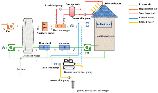
Figure 1.
Schematic figure of the SDW-GSHP hybrid system.
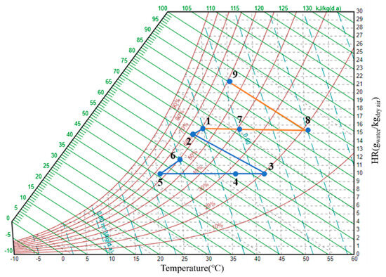
Figure 2.
Thermodynamic process of air treatment.
The studied building is a typical office building with an air conditioning zone of 150 m2, facing south, located in Qingdao, where the climate is characterized by hot summers and cold winters. The description of the building is shown in Table 1. Equipment, lighting, and occupants follow temporal distributions as depicted in Figure 3. The climate data used for the simulation is taken from the TRNSYS weather data file and is as follows: Table 2.

Table 1.
Parameters of the Building Type.
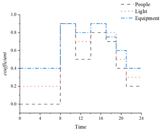
Figure 3.
Time-dependent distribution of working day equipment, lighting, and occupants.
Table 2.
Weather data in Qingdao in July.
2.2. System Control
In the system, three main controllers are employed to ensure system operation. The temperature differential between the water in the source-side loop exiting the storage tank and the water at the collector’s output is monitored by the differential controller in the solar circuit. Control the collector loop pump to be on when the temperature of the fluid leaving the collector is 5 °C higher than the fluid coming from the tank to the collector, turn off when the temperature of the fluid leaving the collector is less than 2 °C below the fluid coming from the tank to the collector, and turn off if the fluid supplying the hot water is higher than 90 °C.
If the temperature difference exceeds the user-defined value, the controller will activate the source-side pump. To maintain the working fluid’s temperature below the boiling point as it passes through the solar collector, an additional controller is incorporated into the solar circuit.
The temperature control in the system is achieved by the type108 module. This ON/OFF differential device simulates a room thermostat. It outputs a signal to control the start and stop of the GSHP system. The humidity control is taken by the type23 module, which employs a PID controller. PID control, or Proportional-Integral-Derivative Control, can be divided into P, PI, PD, and PID control, according to application conditions and control objects. In this paper, PI control, or proportional-integral control, is used for indoor humidity control. The control variable of the Type23 module is the design humidity of the building. Therefore, the Type23 module will output the corresponding control signal according to the real-time relative humidity of the room. In TRNSYS, the control signal can be converted to moisture content using equation 1. This moisture content is set as the humidity set point of the DW outlet, and the DW system adjusts the dehumidification amount to reach the set point by changing the regeneration temperature. A detailed description can be seen in Table 2.
where: is the setpoint for the controller; is the humidity ratio.
A PI controller has many advantages, such as fast response, stability, robustness, and wide applicability [20]. It can respond quickly to changes in the system, decrease steady-state errors, and tune the parameters, which are suitable for high-precision and high-stability systems.
2.3. System Model
This paper presents the modeling and investigation of an SDW-GSHP air conditioning system using TRNSYS. The TRNSYS 18 software was utilized for modeling and simulating the system using a transient system simulation approach. The system simulation model is depicted in Figure 4. The SDW-GSHP air conditioning system’s primary component parameters can be found in Table 3. The simulation model of an electric heating-powered desiccant wheel and ground-source heat pump (EDW-GSHP) air conditioning system is shown in Figure 5. The simulation is carried out under the same meteorological parameters as the SDW-GSHP air conditioning system.
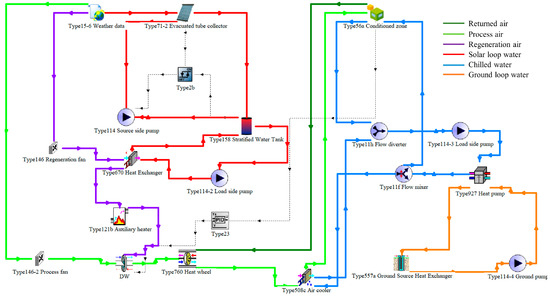
Figure 4.
TRNSYS simulation model of the SDW-GSHP air conditioning system.
Table 3.
Parameters of the primary component of the SDW-GSHP air conditioning system.
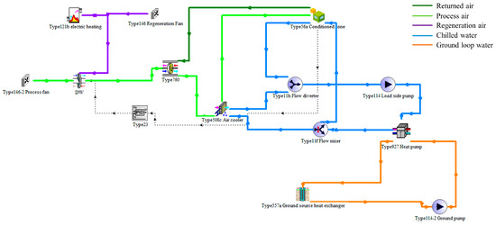
Figure 5.
TRNSYS simulation model of the EDW-GSHP air conditioning system.
2.4. Mathematical Equations
2.4.1. Vacuum Tube Solar Collector
A vacuum tube solar collector was used in the simulation, and the model was built using the solar collector’s thermal efficiency equation. The conventional quadratic (or linear) efficiency equation is shown below, and it represents the dependence of the thermal efficiency on the global radiation incident on the solar collector (Tilted surface), ambient temperature, and the temperature of the fluid in the solar collector.
where: is the correlation coefficient of the efficiency equation of a solar collector; is the fluid temperature fluid and is the ambient temperature; is the total radiation intensity of the solar radiation.
The solar collectors were designed to generate enough heat to maintain the DW’s continuous operation. The total collector area was calculated using the following formula:
where is the area of the solar collectors.
2.4.2. Desiccant Wheel
In this paper, the desiccant wheel was simulated using type 1716b from the TRNSYS library, with silica gel serving as the adsorbent material. Because silica gel has broad market availability, a low cost, and a reasonably high water adsorption rate. The DW model is based on two potential functions derived by Howe [23] and revised by Schultz et al. [24]. Given the temperature of the process air intake, as well as the humidity ratios of the process and regeneration air inlets and the humidity ratio of the process air outlet, it is possible to calculate the regeneration air temperature.
Two potential functions, F1 and F2, are obtained by the following equation:
where T and d are the dry bulb temperature and humidity ratio of the process air, respectively. Corrections to the two potential functions above are made using two effectiveness values.
where: D is the actual outlet state; P and R represent the process side and the regeneration side, respectively.
2.4.3. Air Cooler
The heat transfer between the airflow and the fluid in an air cooler is calculated using the bypass factor method. In this method, a portion of the airflow passes through the coil and is discharged in a saturated state, while the remaining airflow bypasses the coil without undergoing any change. Then, the two streams of airflow are mixed, and the outlet state point is calculated accordingly. The fluid cooling rate is calculated using the following equation [25].
where: is the mass flow rate of fluid; and are the enthalpies of Fluid; is the bypass factor.
The outlet state point of air can be calculated using Equations (8) and (9), respectively.
2.4.4. Tank
In the simulation, the hot water tank was a stratified storage tank with N completely mixed isothermal nodes. Heat was transferred between two adjacent nodes by fluid movement and conduction. A fixed node energy balance was provided by [26]:
where: M is the mass of fluid in the nth tank section; is the specific heat of the working fluid; T is the temperature of the working fluid; m is the working fluid mass flow rate; and U is the tank loss coefficient.
2.5. Performance Indices
The COP, electrical power consumption, and SF are used to evaluate the performance of the SDW-GSHP air conditioning system.
The cooling capacity (Qcc) of the system is expressed by [27]:
where: is the mass flow rate of process air; and are the enthalpies of process air at states 1 and 4, respectively.
The total energy consumption of the system [28] is calculated using the following equation:
where: represents the fan’s power consumption; represents the auxiliary heat source power consumption; represents the ground-source heat pump power consumption.
The regeneration heat is calculated by the following formula [29]:
where: is the mass flow rate of regeneration air; and are the enthalpies of regeneration air at states 7 and 8, respectively.
The COP of the system is calculated using the following equation [30]:
The solar fraction (SF) is the ratio of the available energy gained from the solar collector to the regeneration heat [31]. The expression is as follows:
where: is the available energy gained by solar collectors.
3. Results
The cooling and dehumidification performance and energy consumption characteristics of the system were simulated during a typical summer week (15 July to 22 July) in Qingdao. Figure 6a,b illustrate the hourly variations in outdoor temperature, humidity, and indoor room temperature, respectively. The indoor relative humidity fluctuated between 57 and 61%. When the maximum outdoor humidity ratio was 18.8 g/kg, the indoor humidity ratio was 7.26 g/kg. It follows that the process air’s humidity could be effectively decreased by the DW. During the working hours (8:00–18:00), the indoor temperature varied between 25.8 and 26.2 °C. The maximum outdoor air temperature was 32 °C, and the indoor air temperature was 25.8 °C. Therefore, the system could effectively maintain indoor air temperature and relative humidity within the comfort zone during the working hours. During non-working hours (0:00–8:00, 18:00–24:00), the air processed by the DW was cooled through an air cooling coil and then met dehumidification requirements before being supplied into the room. At this time, the heat load in the room was completely generated by equipment, and the outdoor air temperature was relatively low, which resulted in a lower indoor temperature compared with the indoor temperature during working hours. The hourly variation in air cooler and radiant panel outlet temperatures is shown in Figure 6c. During the working hours (8:00–18:00), the temperature of the air cooler and the radiant panel outlet were in the range of 9.6–20.4 °C and 17.4–21.8 °C, respectively. As can be seen from Figure 6a, the temperature range was sufficient to handle indoor sensible heat loads and process air sensible heat loads. The dehumidification amount of the DW was adjusted by the proportional-integral controller according to the regeneration temperature. Figure 6d shows the hourly temperature at the inlet and outlet of regeneration air. The regeneration temperature is between 21.9 and 60 °C. When the regeneration temperature is lower than the process air temperature, dehumidification of the air is not required.
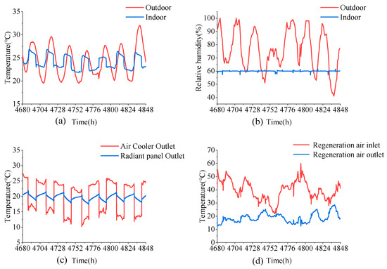
Figure 6.
Hourly variation in temperature and humidity. (a) outdoor temperature and air-conditioned room temperature. (b) outdoor humidity and air-conditioned room humidity. (c) air cooler and radiant panel outlet temperature. (d) regeneration air inlet and regeneration air outlet temperature.
Figure 7 shows the COP of two systems: system 1, which utilizes solar energy and electric heating for regeneration, and system 2, which relies only on electric heating for regeneration. In the majority of hours, system 1 shows a much higher COP compared with system 2. However, in certain hours, the COP of system 1 is lower than that of system 2. This variation is due to the impact of solar radiation on system 1 during these specific hours, which leads to increased consumption of auxiliary electric heating. Throughout the simulation, the average COP of systems 1 and 2 was 2.16 and 1.52, respectively. Consequently, system 1 not only ensures indoor thermal comfort but also improves energy efficiency. The accumulative power consumption of system1 and 2 is shown in Figure 8. Obviously, the power consumption of system 1 is much lower than that of system 2. Hourly simulations were conducted for a typical cooling month (July), and Figure 9 illustrates the total energy consumption of components in systems 1 and 2 in July. The energy consumption of the water pump and ground-source heat pump in system 1 was slightly higher than that in system 2. Because the solar energy collection system in system 1 required a heat collection pump. The electricity consumption for heating the regenerative air in auxiliary heat sources for system 1 and 2 was 535 KWh and 2308 KWh, respectively. Overall, System 1 saved about 43.71% of the electricity compared to system 2.
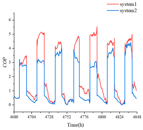
Figure 7.
Hourly variation in COP.
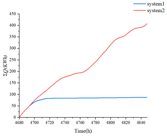
Figure 8.
Accumulative power consumption of system1 and system 2.
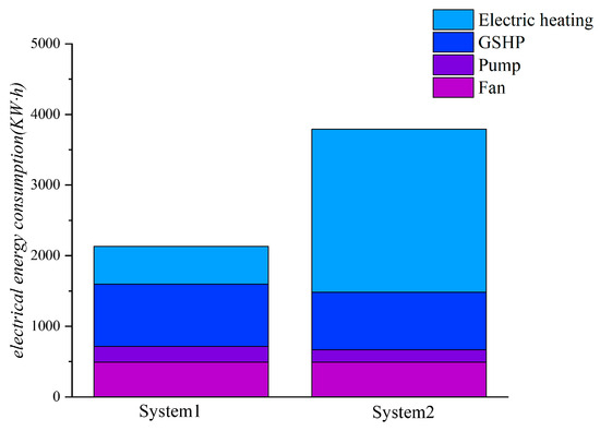
Figure 9.
Power consumption of each device in system 1 and System 2 in a typical cold month.
The hourly variation in heating coil transfer heat, auxiliary heat source consumption, and regeneration heat are shown in Figure 10. The maximum heat transfer of the heating coil and regeneration heat were 7.88 KW and 6.38 KW, respectively. The maximum auxiliary heat sources consumed by the system were 6.11 KW. As seen in Figure 10, in the early stages of system operation, the heat provided by the heating coil was very low due to the intermittent solar radiation. However, the system required a higher regeneration heat, and the heat of the regeneration air was mainly provided by the auxiliary heat source. During the day, as the system ran, the solar collector absorbed solar radiation. The heat provided by the heating coil gradually increased, and a portion of the heat was stored in the thermal storage tank. At night, due to the lack of solar radiation, the solar collector stopped providing heat, which resulted in decreasing the heat provided by the heating coil.
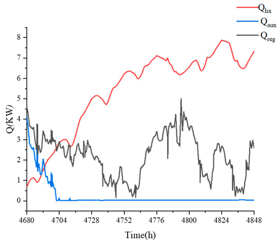
Figure 10.
Hourly variation in heating coil transfer heat, auxiliary heat source consumption, and regeneration heat.
For the desiccant cycle, SF quantifies the portion of driving energy supplied by the solar system. A higher SF value indicates that the auxiliary heat source provides a lower percentage of regeneration heat. The hourly variation in SF in the SW-GSHP air conditioning system is illustrated in Figure 11. In the early stages of system operation, on the one hand, the available energy gained from the solar collector was low. On the other hand, when outdoor air humidity was high, a higher regeneration temperature was required to drive the DW. Both of them cause lower SF. As the system operated, more and more heat was stored in the tank. The dehumidification cycle was mainly driven by solar energy, so SF increased. When SF = 1, the heat of the regeneration air was completely provided by the solar heat collection system.
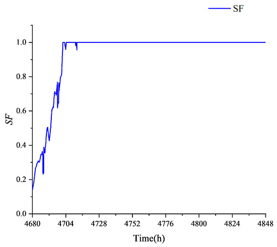
Figure 11.
Hourly variation in SF.
It is noteworthy that as the system stabilizes, there is enough heat in the tank to meet the regeneration needs of the DW. Consequently, surplus solar heat can be stored for diverse applications during specific time periods.
4. Conclusions
Conventional air refrigeration systems usually handle both sensible and latent heat loads. However, this way is obviously impractical for regions with moderate temperatures and high humidity. Therefore, to achieve independent control of temperature and humidity while maximizing the use of renewable energy, this study conducted dynamic simulations on the SDW-GSHP air conditioning system. In this system, a DW system driven by solar energy and auxiliary heat sources were used to handle latent heat loads, while a ground-source heat pump handled sensible heat loads through a ground heat exchanger. Simulations were conducted in Qingdao, Shandong Province, China.
The results show that the system has excellent thermal comfort and a high coefficient of performance. During the working hours (8:00–18:00), the temperature of the air-conditioned room was maintained at 25.8~26.2 °C, and the relative humidity was 57~61%, which provided a comfortable indoor thermal and humid environment. Compared with traditional vapor compression air conditioning systems [32], the dehumidification effect is obvious. When the outdoor humidity is high, the designed humidity can still be achieved. The GSHP provided high-temperature chilled water (9.3 to 12.7 °C) to handle indoor sensible heat loads. To minimize fluctuations in indoor relative humidity, the dehumidification amount of the DW was controlled by the temperature of the regenerative air, with a temperature range of 21.9 to 60 °C. The SDW-GSHP air conditioning system saves 43.71% of electric energy compared with the DW air conditioning system, which relies on electric heating for regeneration. The average COP of the SDW-GSHP air conditioning system was 2.16, an improvement of 29.6%. The regenerative heat of the DW in the SDW-GSHP air conditioning system was provided by solar energy and auxiliary heat sources. To investigate the efficiency of solar energy, the SF was used to measure the proportion of regenerative heat from the solar energy collection system. Throughout the simulation period, the SF showed a gradually increasing trend until SF = 1. This indicated that the regeneration heat mainly came from the solar energy collection system. Therefore, the SDW-GSHP air conditioning system provides more satisfactory cooling and energy performance through temperature and humidity control compared with conventional refrigeration systems.
The climate of Qingdao in the summer is hot and humid. In comparison to conventional refrigeration systems, solar energy’s participation is essential for having the ability to save energy. Similar environments in other hot, muggy cities that need separate temperature and humidity management can also benefit from the application of this solar air conditioning technique.
Through the above research, we can know that the SDW-GSHP air conditioning system has broad applications. Next, we will conduct more in-depth research through experiments.
Author Contributions
Conceptualization, Y.W. and Y.M.; methodology, Y.W.; software, Y.W.; validation, T.S., L.H. and Y.W.; writing—original draft preparation, Y.W.; writing—review and editing, Y.M; All authors have read and agreed to the published version of the manuscript.
Funding
This research was funded by National Natural Science Foundation of China (Grant No. 51575286), Key R&D plan of Shandong Province (public welfare science and technology research) (Grant No. 2018GGX 105007).
Institutional Review Board Statement
Not applicable.
Informed Consent Statement
Not applicable.
Data Availability Statement
The data presented in this study are available on request from the corresponding author.
Conflicts of Interest
The authors declare no conflicts of interest.
Nomenclature
| Nomenclature | |
| A | Area (m2) |
| a | Collector efficiency parameter |
| Cp | Specific heat at constant pressure (kJ·kg−1·K−1) |
| F1 | Potential functions |
| F2 | Potential functions |
| h | Specific enthalpy (kJ·kg−1) |
| IT | Global radiation incident on the solar collector (kJ·h−1·m−2) |
| Q | Heat transfer capacity (KW) |
| T | Temperature (K) |
| d | Humidity ratio |
| f | Bypass factor |
| V | Volume (m3) |
| m | Mass flow rate (kg·s−1) |
| U | Loss coefficient (kJ·h−1·m−2·K−1) |
| SF | Solar fraction |
| Abbreviations | |
| DW | Desiccant whell |
| SDW | Solar powered dehumidification wheel |
| GSHP | Ground source heat pump |
| Subscripts | |
| a | ambient |
| in | inlet |
| P | process air |
| R | regeneration air |
| Out | outlet |
| t | total |
| CC | cooling capacity |
| aux | auxiliary heat |
References
- Ma, Z.; Ren, H.; Lin, W. A Review of Heating, Ventilation and Air Conditioning Technologies and Innovations Used in Solar-Powered Net Zero Energy Solar Decathlon Houses. J. Clean. Prod. 2019, 240, 118158. [Google Scholar] [CrossRef]
- Pérez-Lombard, L.; Ortiz, J.; Pout, C. A Review on Buildings Energy Consumption Information. Energy Build. 2008, 40, 394–398. [Google Scholar] [CrossRef]
- Zhong, Y.; Qin, C.K.; Xu, J.H. Application of active dehumidification wheel to air conditioning systems for civil buildings. Heat. Vent. Air Cond. 2006, 29–34. [Google Scholar]
- Rambhad, K.S.; Walke, P.V.; Tidke, D.J. Solid Desiccant Dehumidification and Regeneration Methods-A Review. Renew. Sustain. Energ. Rev. 2016, 59, 73–83. [Google Scholar] [CrossRef]
- Ge, T.S.; Dai, Y.J.; Wang, R.Z. Review on Solar Powered Rotary Desiccant Wheel Cooling System. Renew. Sustain. Energy Rev. 2014, 39, 476–497. [Google Scholar] [CrossRef]
- Preisler, A.; Brychta, M. High Potential of Full Year Operation with Solar Driven Desiccant Evaporative Cooling Systems. Energy Procedia 2012, 30, 668–675. [Google Scholar] [CrossRef][Green Version]
- Bourdoukan, P.; Wurtz, E.; Joubert, P.; Sperandio, M. Potential of Solar Heat Pipe Vacuum Collectors in the Desiccant Cooling Process: Modelling and Experimental Results. Sol. Energy 2008, 82, 1209–1219. [Google Scholar] [CrossRef]
- Li, H.; Dai, Y.J.; Li, Y.; La, D.; Wang, R.Z. Case Study of a Two-Stage Rotary Desiccant Cooling/Heating System Driven by Evacuated Glass Tube Solar Air Collectors. Energy Build. 2012, 47, 107–112. [Google Scholar] [CrossRef]
- Comino, F.; Castillo González, J.; Navas-Martos, F.J.; Ruiz De Adana, M. Experimental Energy Performance Assessment of a Solar Desiccant Cooling System in Southern Europe Climates. Appl. Therm. Eng. 2020, 165, 114579. [Google Scholar] [CrossRef]
- Zhou, X. Thermal and Energy Performance of a Solar-Driven Desiccant Cooling System Using an Internally Cooled Desiccant Wheel in Various Climate Conditions. Appl. Therm. Eng. 2021, 185, 116077. [Google Scholar] [CrossRef]
- Büker, M.S.; Parlamış, H.; Alwetaishi, M.; Benjeddou, O. Experimental Investigation on the Dehumidification Performance of a Parabolic Trough Solar Air Collector Assisted Rotary Desiccant System. Case Stud. Therm. Eng. 2022, 34, 102077. [Google Scholar] [CrossRef]
- Liu, Y.; Chen, Y.; Wang, D.; Liu, J.; Li, L.; Luo, X.; Wang, Y.; Liu, J. Performance Evaluation of a Hybrid Solar Powered Rotary Desiccant Wheel Air Conditioning System for Low Latitude Isolated Islands. Energy Build. 2020, 224, 110208. [Google Scholar] [CrossRef]
- Olmuş, U.; Güzelel, Y.E.; Büyükalaca, O. Seasonal Analysis of a Desiccant Air-Conditioning System Supported by Water-Cooled PV/T Units. Energy Build. 2023, 291, 113101. [Google Scholar] [CrossRef]
- Olmuş, U.; Güzelel, Y.E.; Pınar, E.; Özbek, A.; Büyükalaca, O. Performance Assessment of a Desiccant Air-Conditioning System Combined with Dew-Point Indirect Evaporative Cooler and PV/T. Sol. Energy 2022, 231, 566–577. [Google Scholar] [CrossRef]
- Baniyounes, A.M.; Rasul, M.G.; Khan, M.M.K. Experimental Assessment of a Solar Desiccant Cooling System for an Institutional Building in Subtropical Queensland, Australia. Energy Build. 2013, 62, 78–86. [Google Scholar] [CrossRef]
- Liu, Y.; Meng, D.; Chen, S. Feasibility Study on an Energy-Saving Desiccant Wheel System with CO2 Heat Pump. IOP Conf. Ser. Earth Environ. Sci. 2018, 121, 052037. [Google Scholar] [CrossRef]
- Ge, F.; Wang, C. Exergy Analysis of Dehumidification Systems: A Comparison between the Condensing Dehumidification and the Desiccant Wheel Dehumidification. Energy Convers. Manag. 2020, 224, 113343. [Google Scholar] [CrossRef]
- Tian, S.; Su, X.; Li, H.; Huang, Y. Using a Coupled Heat Pump Desiccant Wheel System to Improve Indoor Humidity Environment of nZEB in Shanghai: Analysis and Optimization. Build. Environ. 2021, 206, 108391. [Google Scholar] [CrossRef]
- Tian, S.; Su, X.; Geng, Y.; Li, H.; Liang, Y.; Di, Y. Heat Pump Combined with Single-Stage or Two-Stage Desiccant Wheel System? A Comparative Study on Different Humidity Requirement Buildings. Energy Convers. Manag. 2022, 255, 115345. [Google Scholar] [CrossRef]
- Song, Y.; Wu, S.; Yan, Y.Y. Control Strategies for Indoor Environment Quality and Energy Efficiency-a Review. Int. J. Low-Carbon Technol. 2015, 10, 305–312. [Google Scholar] [CrossRef]
- López, J.M.C.; Hernández, F.F.; Muñoz, F.D.; Andrés, A.C. The Optimization of the Operation of a Solar Desiccant Air Handling Unit Coupled with a Radiant Floor. Energy Build. 2013, 62, 427–435. [Google Scholar] [CrossRef]
- Sokhansefat, T.; Kasaeian, A.; Rahmani, K.; Heidari, A.H.; Aghakhani, F.; Mahian, O. Thermoeconomic and Environmental Analysis of Solar Flat Plate and Evacuated Tube Collectors in Cold Climatic Conditions. Renew. Energy 2018, 115, 501–508. [Google Scholar] [CrossRef]
- Howe, R. Model and Performance Characteristics of a Commercially-Sized Hybrid Air Conditioning System Which Utilizes a Rotary Desiccant Dehumidifier. Ph.D. Thesis, University of Wisconsin-Madison, Madison, WI, USA, 1983. [Google Scholar]
- Schultz, K.; Beckman, W. The Performance of Desiccant Dehumidifier Air-Conditioning Systems Using Cooled Dehumidifiers. Ph.D. Thesis, University of Wisconsin-Madison, Madison, WI, USA, 1983. [Google Scholar]
- Trnsys17, TESSLibs17, Volume 06 (HVAC Library Mathematical Reference). Available online: https://studylib.net/doc/26139821/trnsys-17---mathematical-reference (accessed on 20 January 2024).
- Trnsys 18, Volume 4 (Mathematical Reference). Available online: https://studylib.net/doc/26018127/trnsys18-%E2%80%93-mathematical-reference (accessed on 20 January 2024).
- Kim, M.-H.; Dong, H.-W.; Park, J.-Y.; Jeong, J.-W. Primary Energy Savings in Desiccant and Evaporative Cooling-Assisted 100% Outdoor Air System Combined with a Fuel Cell. Appl. Energy 2016, 180, 446–456. [Google Scholar] [CrossRef]
- Sheng, Y.; Zhang, Y.; Sun, Y.; Fang, L.; Nie, J.; Ma, L. Experimental Analysis and Regression Prediction of Desiccant Wheel Behavior in High Temperature Heat Pump and Desiccant Wheel Air-Conditioning System. Energy Build. 2014, 80, 358–365. [Google Scholar] [CrossRef]
- Kumar, A.; Yadav, A. Experimental Investigation of Solar Driven Desiccant Air Conditioning System Based on Silica Gel Coated Heat Exchanger. Int. J. Refrig.-Rev. Int. Froid 2016, 69, 51–63. [Google Scholar] [CrossRef]
- Mucke, L.; Fleig, D.; Vajen, K.; Jordan, U. Hybrid Liquid Desiccant Air-Conditioning Systems: A Conceptual Study with Respect to Energy Saving Potentials. Int. J. Refrig.-Rev. Int. Froid 2016, 69, 64–73. [Google Scholar] [CrossRef]
- Rayegan, S.; Motaghian, S.; Heidarinejad, G.; Pasdarshahri, H.; Ahmadi, P.; Rosen, M.A. Dynamic Simulation and Multi-Objective Optimization of a Solar-Assisted Desiccant Cooling System Integrated with Ground Source Renewable Energy. Appl. Therm. Eng. 2020, 173, 115210. [Google Scholar] [CrossRef]
- Fong, K.F.; Lee, C.K.; Chow, T.T.; Fong, A.M.L. Investigation on Solar Hybrid Desiccant Cooling System for Commercial Premises with High Latent Cooling Load in Subtropical Hong Kong. Appl. Therm. Eng. 2011, 31, 3393–3401. [Google Scholar] [CrossRef]


Disclaimer/Publisher’s Note: The statements, opinions and data contained in all publications are solely those of the individual author(s) and contributor(s) and not of MDPI and/or the editor(s). MDPI and/or the editor(s) disclaim responsibility for any injury to people or property resulting from any ideas, methods, instructions or products referred to in the content. |
© 2024 by the authors. Licensee MDPI, Basel, Switzerland. This article is an open access article distributed under the terms and conditions of the Creative Commons Attribution (CC BY) license (https://creativecommons.org/licenses/by/4.0/).