Abstract
Compliant mechanisms are popular to the applications of micro/nanoscale manipulations. This paper proposes a novel triaxial parallel-kinematic compliant manipulator inspired by the Tripteron mechanism. Compared to most conventional triaxial compliant mechanisms, the proposed manipulator has the merits of structure compactness and being free of assembly error due to its unique configuration and the utilize of 3D printing technology. The compliance matrix modeling method is employed to determine the input stiffness of the compliant manipulator, and it is verified by finite-element analysis (FEA). Results show that the deviations between simulation works and the derived analytical models are in an acceptable range. The simulation results also reveal that the compliant manipulator can achieve a 16 m × 16 m × 16 m cubic workspace. In this motion range, the observed maximum stress is much lower than the yield strength of the material. Moreover, the dynamic characteristics of the manipulator are investigated via the simulations as well.
1. Introduction
Piezo-driven compliant mechanisms have received increasing attention in both academic and industrial communities, due to their merits of micro/nanoscale resolution and fast response. They have been widely applied to a variety of fields such as atomic force microscopy [1], precise assembly [2], cell micro-injection [3], micro/nanoscratching [4] and micro electromechanical systems [5]. The compliant mechanisms transmit motion based on the deformation of flexure hinges, which are different from conventional mechanisms on the basis of rigid links and gears. They are capable of overcoming the disadvantages of traditional mechanisms including the backlash and assembly error [6,7]. The piezoelectric actuator (PEA) is a normally-used driving component in compliant mechanisms owing to its high resolution, rapid response and ease of compact size [8,9,10]. With all outstanding superiorities as mentioned, the piezo-driven compliant mechanism has been one of the promising choices for precision manipulators [11,12,13].
The translational XYZ compliant mechanism is a significant manipulator in some applications such as the atomic force microscopy and micro-injection. They can be commonly divided into serial mechanisms and parallel mechanisms based on the kinematic principle. For the serial mechanisms, each of the axes works independently and is easy to control, since they do not have coupling motions between axes. Wadikhaye et al. [14] designed a serial-kinematic XYZ positioner with rapid response and compact structure for the atomic force microscopy. The positioner has a reachable motion range of 8 m × 6 m × 2 m with the frequencies of 10, 7.5 and 64 kHz along the x, y and z-axis, respectively. Kenton et al. [15] proposed a serial-kinematic triaxial compliant mechanism. A positioning range of 9 m × 9 m × 1 m is achieved with the fabricated prototype. The experimental results also demonstrate that the mechanism has the resonant frequencies of 24.2, 6 and 70 kHz along the x, y and z-axis, respectively. A three-axis serial-kinematic positioning device driven by piezoelectric actuators was developed for fast tool servo application [16]. The natural frequencies of the positioner along the x, y and z-axis were measured at 1.06, 0.65 and 0.54 kHz, respectively. However, the accumulation of error is inevitable for the serial structure, and it is at the sacrifice of the natural frequency because the serial connection increases the mass of motion parts of other axes, resulting in different resonant frequencies among axes [17,18].
On the contrary, the motion platform is directly connected with all axes in the parallel mechanisms, so that the cumulative error and motion mass increase can be avoided. Many parallel XYZ compliant mechanisms have been developed due to their virtues of high precision and high resonant frequency. Li et al. [19] proposed a parallel XYZ compliant mechanism with good motion decoupling properties in both the input end and the output platform. In the design, the compound parallelogram flexures were adopted to realize the total decoupling. The finite element analysis (FEA) simulation results show that it has identical dynamic performance in all axes, and experimental results demonstrate that the developed mechanism can achieve submicron accuracy. By introducing the biaxial right circular flexure hinges, Zhu et al. [20] developed a parallel triaxial translational monolithic compliant mechanism, which aims to achieve high bandwidth, high stiffness and high compactness. For the sake of enlarging the mechanism workspace, a 3-DoF XYZ precision positioner based on the modified differential lever amplifier was proposed in the literature of [21].Nonetheless, the base frames in the aforementioned works were not clearly displayed and the overall body sizes were difficult to evaluate. In the literature of [22], a complete parallel XYZ micromanipulator with the base frame was presented. Tang et al. [23] also conceived and designed a decoupled XYZ flexure parallel mechanism mounted on the base frame. Hao et al. [24] developed a 3 DoF translational compliant manipulator with three XY orthogonally-placed flexure mechanisms fixed on the base frame. With the same research group, spatial double four-beam modules were employed in the design of a parallel modular XYZ compliant mechanism referring to a 3-PPPR (P: prismatic, R: revolute) kinematic principle. The developed mechanism also took into account the base frame in the design [25]. In addition, Awtar et al. [26,27] proposed a parallel triaxial translational flexure mechanism mounted on the base with a travel range of 10 mm × 10 mm × 10 mm. Good decoupled translational motions among axes and high stiffness in the rotational motions were observed. However, the body sizes of some of the above-mentioned manipulators are bulky, while the base frame structures are considered. Moreover, the assembly errors between amplifier mechanisms/guidance mechanisms and base frames in these studies are difficult to be avoided.
The kinematics-based approach, the building blocks approach and the topology optimization approach [28,29,30] are three classical compliant mechanisms designing methods. On the basis of the kinematics-based approach, a novel mechanism inspired by the Tripteron [31] is proposed in this paper to solve the aforementioned problems, which may provide an alternative way to construct the parallel XYZ compliant manipulator. 3D printing technology is expected to monolithically fabricate the proposed manipulator for eliminating assembly error and realizing structure compactness. The rest of this paper is structured as follows. Section 2 illustrates the overall configuration and working principle of the parallel XYZ manipulator. In Section 3, the compliance matrix modeling method is utilized to analyse the stiffness/compliance of the manipulator. FEA simulation works are conducted to verify the theoretical analyses in Section 4. Section 5 draws a brief conclusion of this work.
2. Mechanism Design
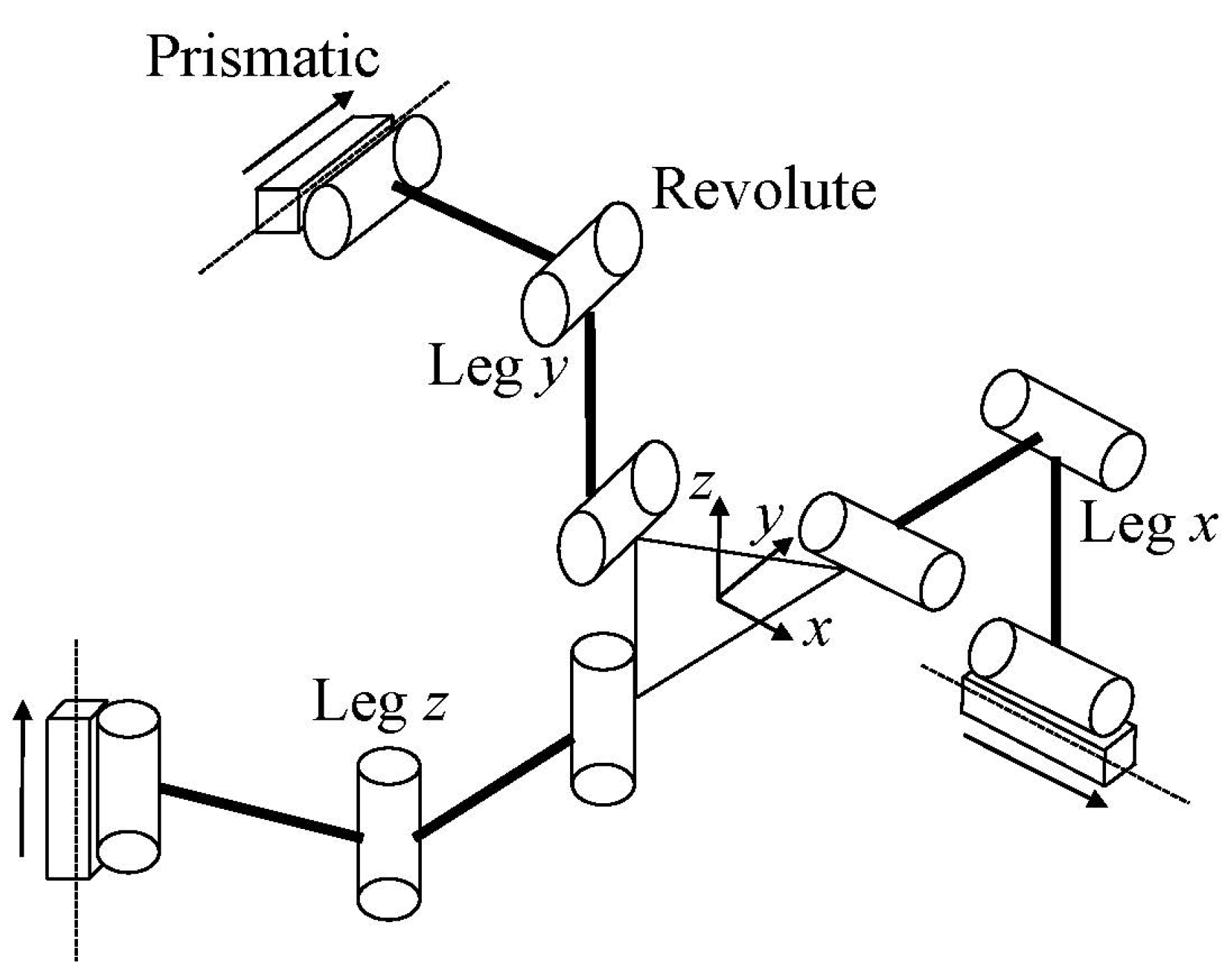
As shown in Figure 1, the Tripteron is a triaxial translational parallel mechanism [31,32]. It is composed of an orthogonally arranged base frame, three kinematically identical legs and an end-effector. Referring to the kinematics model of the Tripteron, the leg has three revolute joints on its own and a prismatic joint connected with the base frame. When the prismatic joint is driven by the linear motor, the end-effector can achieve consistent translational motion along the driving axis. As a result, the Tripteron has three translational motions in the Cartesian coordinate. Investigation into compliant Triteron is still scarce, although a compliant Tripteron has been presented previously, and the kinematostatic model has been established in the literature of [33]. In the reported literature, cruciform hinges were employed, whereas the right circular flexure hinges and beam flexure hinges will be adopted in the current paper. Furthermore, the reported compliant Tripteron is not a monolithic mechanism, which is different from the proposed mechanism in this paper.
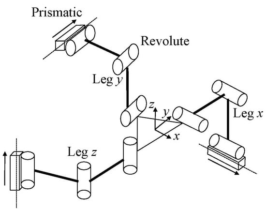
Figure 1.
The kinematic diagram of Tripteron.
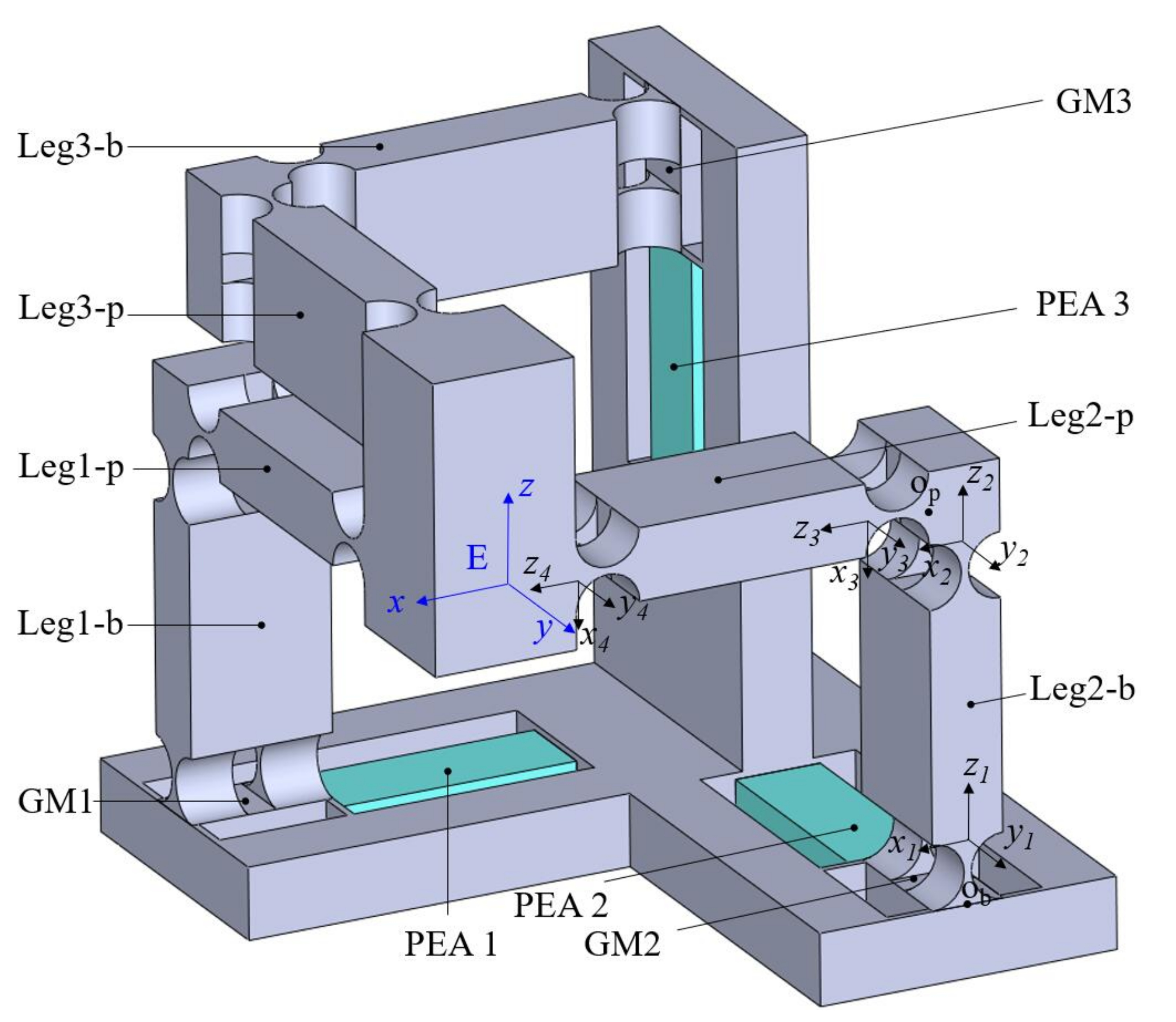
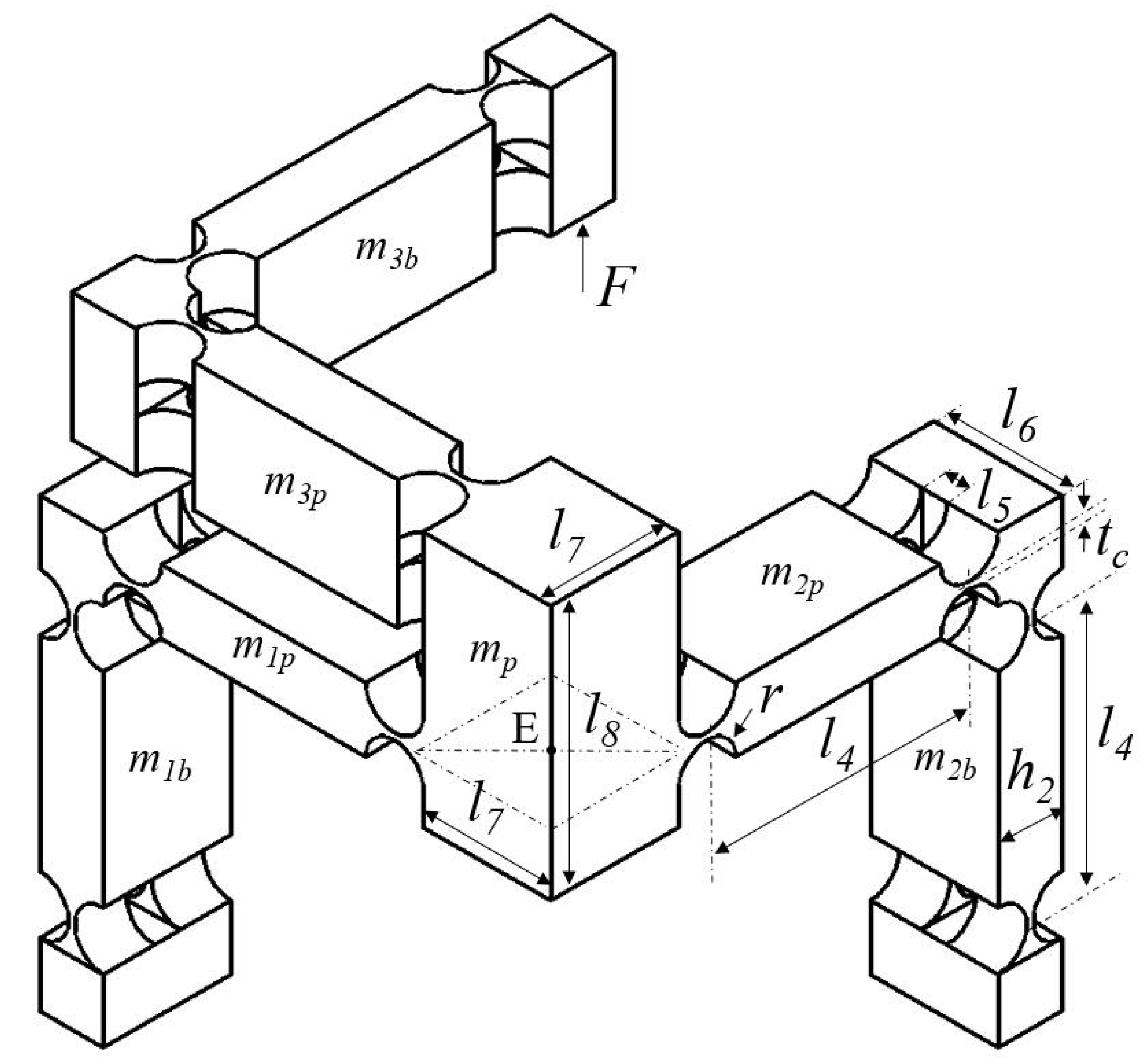
As enumerated above, a new translational XYZ parallel compliant mechanism based on the Tripteron is devised as shown in Figure 2. It consists of a base, three kinematically identical legs and a motion platform. The base structure is a guidance mechanism (GM) embedded with a PEA along each axis of the Cartesian coordinates. The leg is a rectangular-shaped compliant mechanism. The leg is worked as a driving unit while it moves toward the elongation direction of the directly connected PEA, otherwise it works as a passive guidance unit along the other two axes. For the convenience of analyses in the following sections, each leg is further subdivided into leg-p which is directly connected with the platform and leg-b which is directly connected with the base frame.
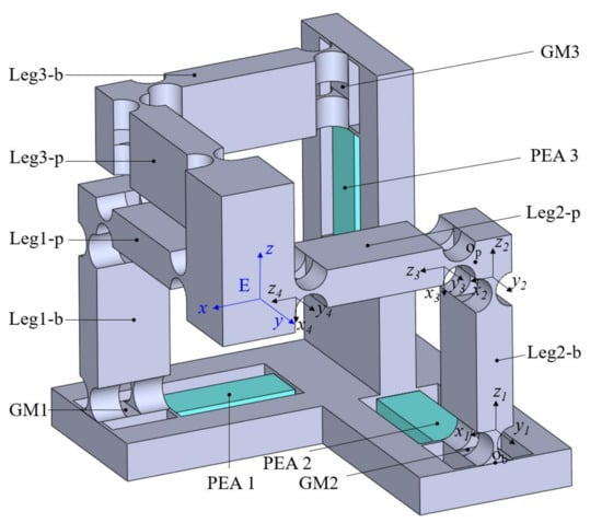
Figure 2.
Mechanical structure of the proposed triaxial compliant manipulator.
The right circular flexure hinge and beam flexure hinge are commonly used flexure hinges. The right circular flexure hinge has the merits of little axis drift, high-precision and high transversal stiffness. The beam flexure hinge can distribute the deformation in the whole beam and avoid the concentration of stress, which provides a larger displacement of deformation without failure. As a result, the GM 1 is constructed with beam flexure hinges, which mainly aims to provide large output displacement. On the other hand, the guidance mechanism has four parallel connected beam flexure hinges, which can avoid the coupled motion caused by other driving units including the transverse motion and twisted deformation. This is significant for protecting the PEAs from being damaged, since they are sensitive to the tangential force and bending deformation. In contrast, the right circular flexure hinges are used in the design of the legs, so that the high lateral stiffness can alleviate the deformation when they are working as driving units, and the compliance can reduce the constraint stiffness when they are working as passive guidance units.
The working principle of the proposed 3-DoF compliant mechanism can be illustrated as follows. The PEA 1 elongates when the voltage is exerted on it, driving the GM 1 and corresponding connected leg toward the positive x-axis, and thus the motion platform moves toward positive x-axis accordingly. Based on the same principle, the motions along y-axis and z-axis can be achieved when the voltages are applied at PEA 2 and PEA 3. As a result, a compliant mechanism with translational 3-DoF is developed.
3. Modeling and Analysis
3.1. Modeling Method
There are many modeling methods for analyzing compliant mechanisms as reviewed in the literature of [34,35,36], including Castigliano’s second theorem, elastic beam theory, compliance matrix modeling (CMM) method, finite element method, pseudo-rigid-body (PRB) method, the chained beam constraint model and the 3-D dynamic stiffness model. Both merits and shortcomings were comprehensively reported. In this paper, the PRB method [37] and CMM method [38,39] are mainly discussed. The PRB method only takes account of the compliance of flexure hinges along the working direction, so that it is not able to achieve a complete compliance analysis. Moreover, it involves loop closure theory, virtual work principle and Lagrange’s equation, which is complex for complicated mechanisms. On the contrary, the CMM method on the basis of Hooke’s law can establish 6-DoF compliance in the space of flexure hinges with high accuracy. Furthermore, it has high calculation efficiency due to the effective operation of matrix with the help of a computer. As a result, the compliance/stiffness of the proposed compliant mechanism in this paper is analyzed based on the compliance matrix modeling method.
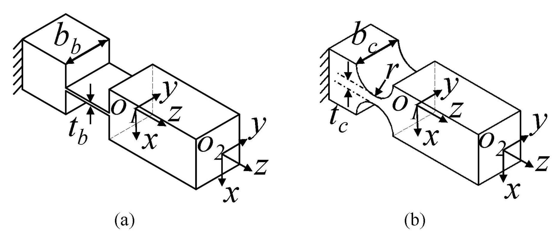
As shown in Figure 3, the compliance matrix in its local coordinate can be expressed as:
where the specific values of compliance factors of different flexure hinges are listed in the literature [40]. Equation (2) shows the conversion of the compliance matrix from its local coordinate to a new coordinate frame.
where is the compliance matrix of the flexure hinge with respect to the fixed-end. The coordinate transformation matrices include the rotational matrix and the translational matrix. , , are the rotational matrices around the x, y and z-axis, and they can be written as
where , and denote the rotation around the corresponding axis. The translational matrix can realize the translation of the compliance matrix, and it is given by
where represents the outer product for a vector , and it can be derived as Equation (7), in which q is the coordinate of the new coordinate system relative to the transferred coordinate frame. The identity matrix I is described by Equation (8).
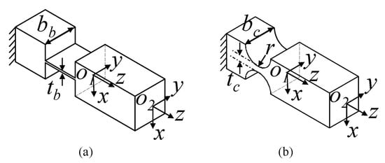
Figure 3.
The beam flexure hinge (a) and right circular flexure hinge (b).
3.2. Input Stiffness of the Proposed Mechanism
For the purpose of determining the compliance/stiffness of the compliant mechanism, the mechanism has been divided into two parts for easy analysis. The compliances/stiffnesses of the guidance mechanisms on the base and legs connected motion platform and guidance mechanisms are separately analyzed first, and are then added together based on the principle of parallel and series connection.
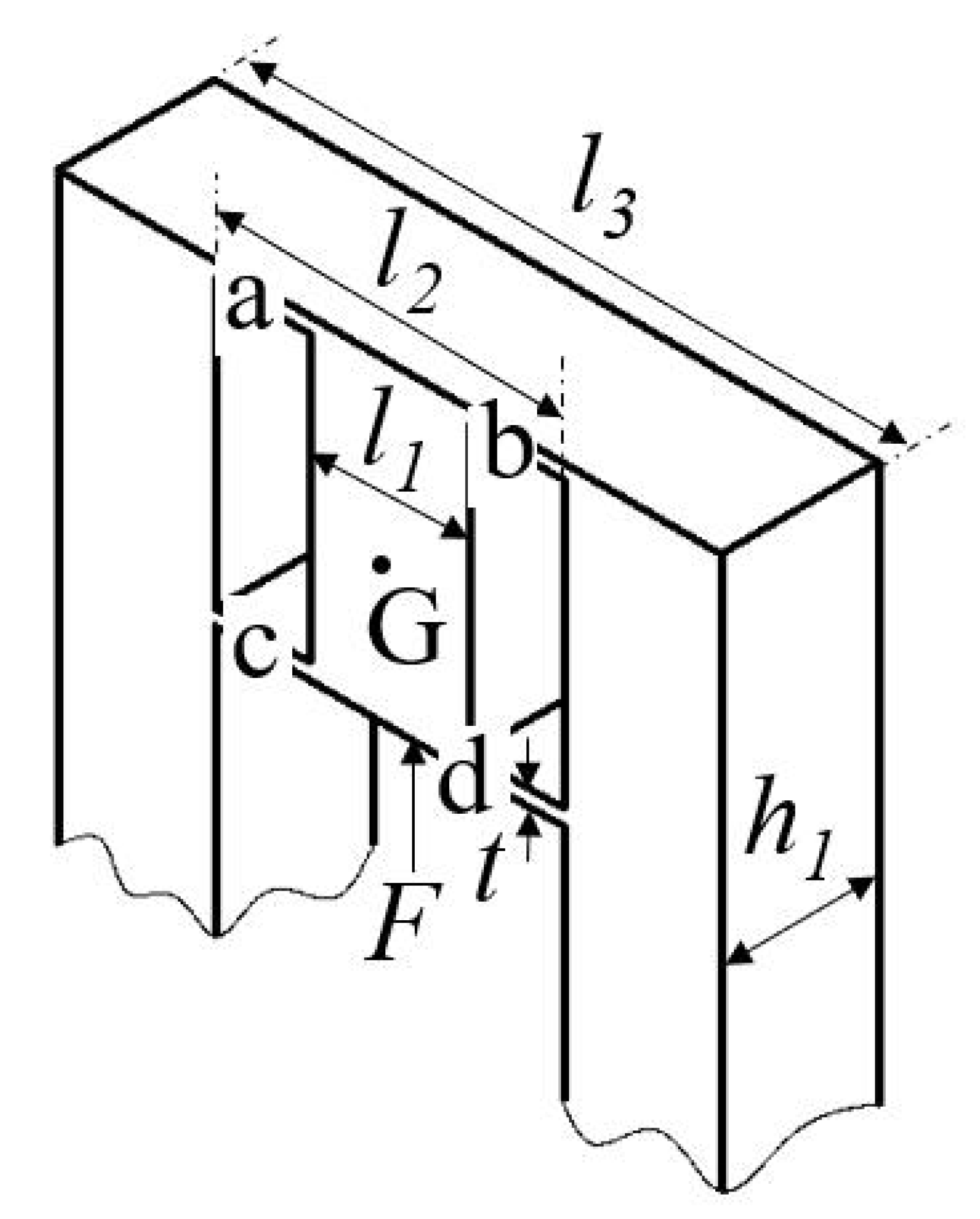
As shown in Figure 4, the GM 3 on the base along the z-axis is picked out for analysis. On the basis of the compliance matrix modeling method, the compliance of hinge a can be generated as
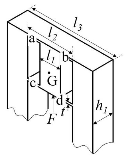
Figure 4.
The guidance mechanism in the base frame.
Due to flexure hinges b and a are symmetric around the x-axis, the compliance of hinge b can be derived as
The above mentioned principle is also applicable to flexure hinges c and d, and thus their compliance matrices can be obtained as
Owing to the four flexure hinges being parallel connected with the motion platform G, the vertical compliance and vertical stiffness can be determined by
Following the previous assumption that the leg connected with the z-axis is the driving unit as shown in Figure 5, and the leg1-p and leg2-p are worked as guidance mechanisms, referring to Figure 2, leg2 is selected for the analysis. Considering that two layers of flexure hinges parallel connect the motion platform and leg2-b, the compliance of point E with respect to the point Op can be derived as
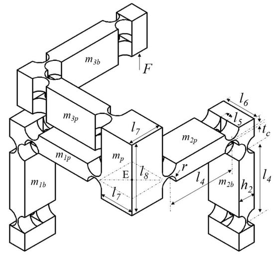
Figure 5.
Schematic of the motion platform and three legs.
Due to leg1-p and leg2-p being parallel connected with the motion platform, and having circular symmetry of around the z-axis, the compliance and the stiffness can be derived as
where is the transformation matrix transferring from leg1-p to leg2-p, and it can be written as
As a result, the total input stiffness along the z-axis of the compliant mechanism can be obtained as the following equation since the GM 3 and guidance mechanism 1p2p are parallel connected with the motion platform
According to the parallel kinematics of the GM 3 and guidance mechanism 1p2p, the output stiffness should be equal to the input stiffness. However, the distortion of the cantilever structure of the driving leg will reduce the output stiffness to some extent. The stiffnesses/compliances of the compliant mechanisms along other two axes can also be determined based on the same principle.
4. Model Validation and Performance Evaluation via FEA
Table 1 shows the structural parameters of the developed parallel triaxial compliant mechanism. 3D printing technology is expected to fabricate the mechanism, due to its capability of manufacturing monolithic complex structure with high dimension accuracy on the basis of the photosensitive resin material [41,42,43]. The detail physical properties of resin are: Young’s modulus GPa, Poisson’s ratio = 0.394, density kg/m, and yield strength MPa. According to the above mentioned parameters, FEA simulations are conducted to validate the established theoretical model and to evaluate the performance of the proposed compliant mechanism with the help of commercial software ANSYS.

Table 1.
Dimensional parameters of the proposed triaxial compliant manipulator.
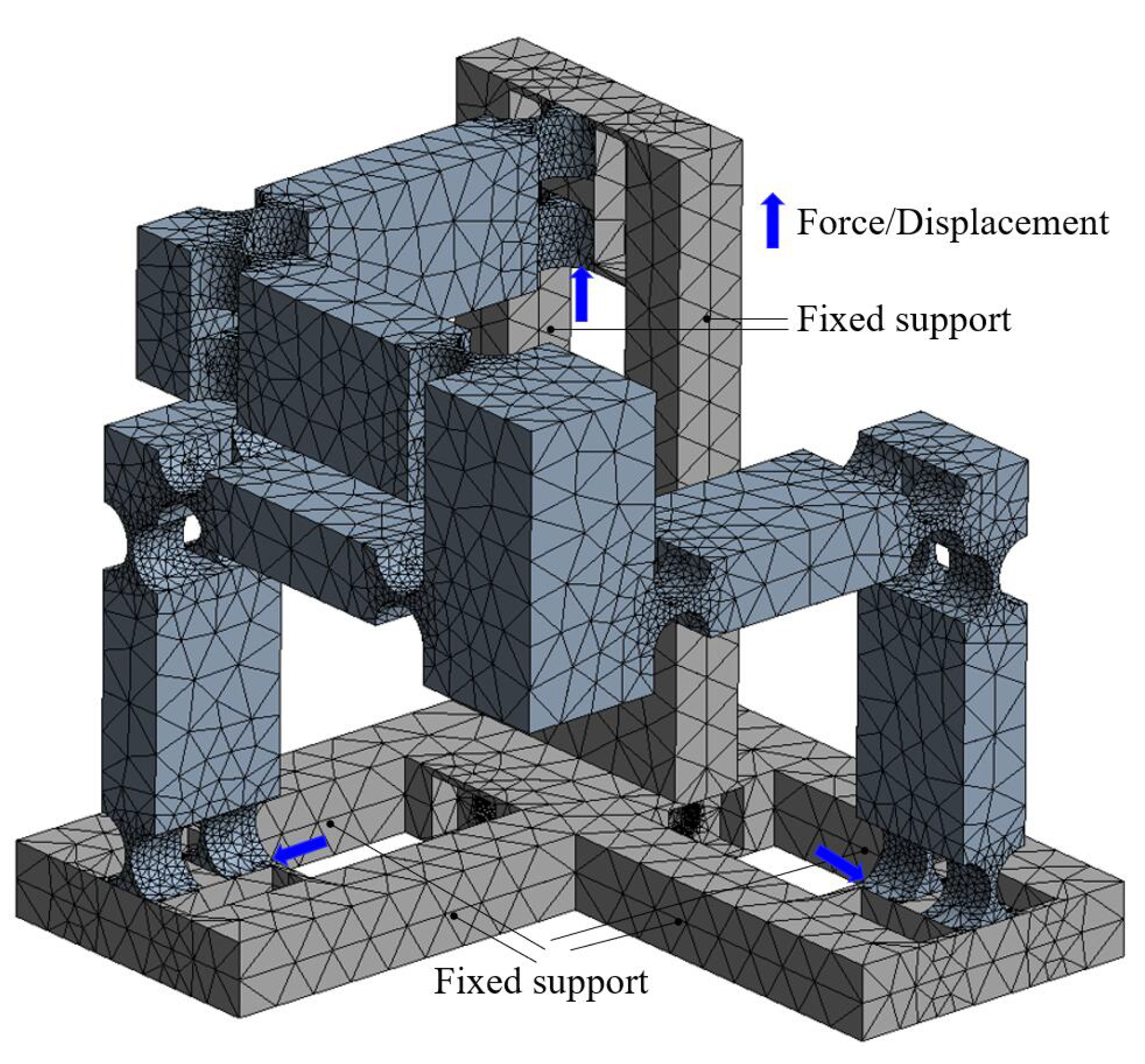
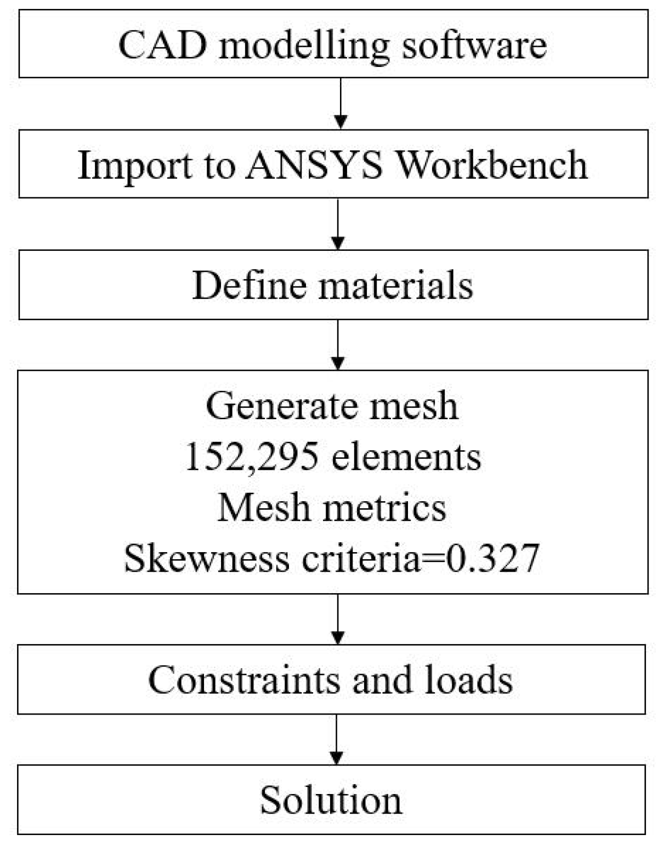
The details of the FEA model are shown in Figure 6, including the constraints, loads, etc. In addition, a flowchart of conducting the FEA simulations is also given in Figure 7. Starting from building the 3-D model of the compliant manipulator via the CAD modelling software, the model is then imported to the ANSYS workbench to perform the simulation analysis. During the simulation, the material of the mechanism was defined according to the aforementioned details of the material properties. Following is the mesh generation. The mesh has 152,295 elements. The skewness criteria mesh metrics is adopted to evaluate the mesh quality and the average value is 0.327, which shows that it has a very good quality. After that, the constraints and loads are defined in the model, and the simulation results can be obtained after the calculation.
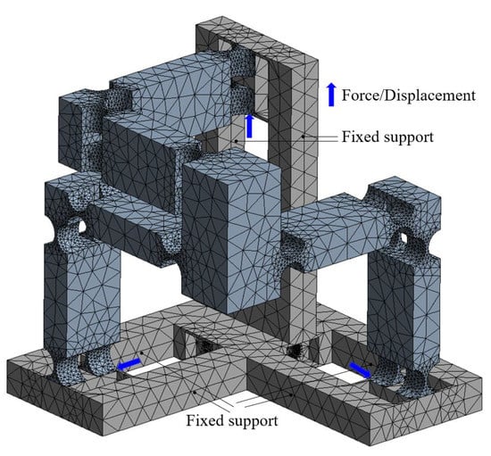
Figure 6.
Details of the FEA model.
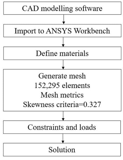
Figure 7.
Flowchart of the FEA simulation.
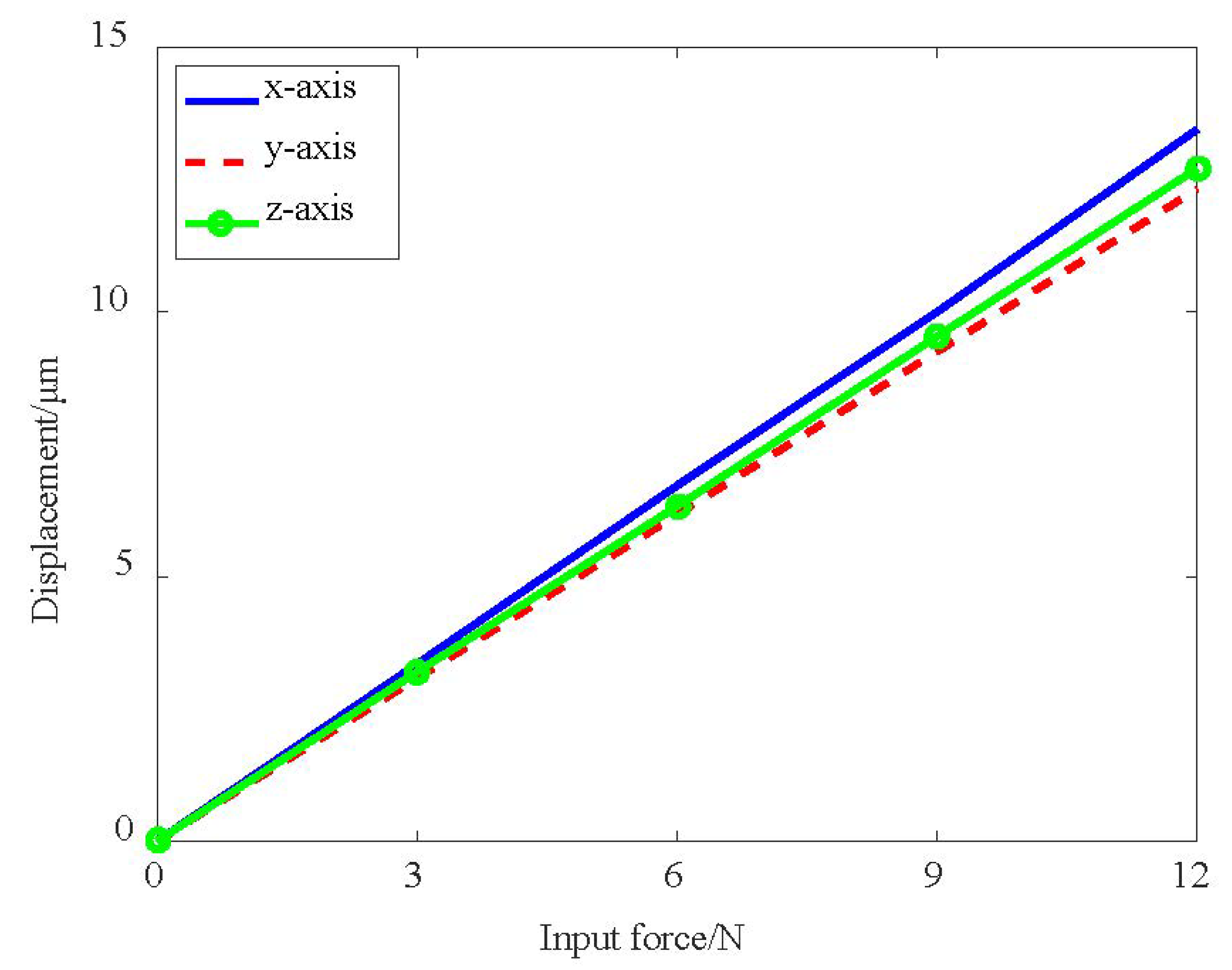
The correlation between the output displacement of the moving platform and the input force is shown in Figure 8. In the figure, three almost coinciding straight lines can be seen, which means that the three axes have a nearly identical linear relationship. The input stiffness is derived by dividing the input force with the output displacement of the moving platform, which is the reciprocal of the slope of the line in Figure 8. The comparison between analytical models and simulation results are given in Table 2. The deviations are mainly induced by the deformation of the driving legs due to the cantilever structure, which can be further explained in the next discussion of motion loss.
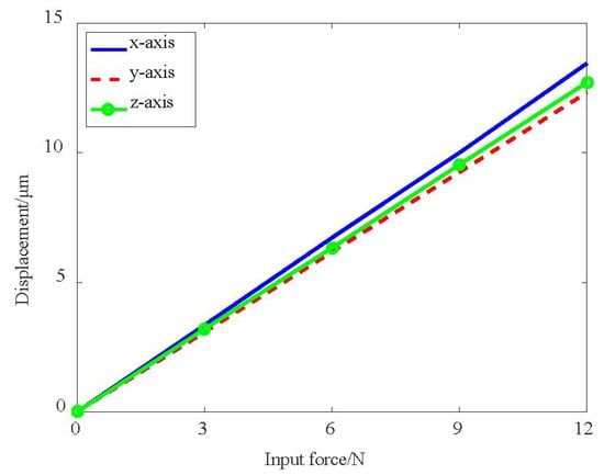
Figure 8.
The correlation between input force and output displacement.

Table 2.
Comparison results of input stiffness.
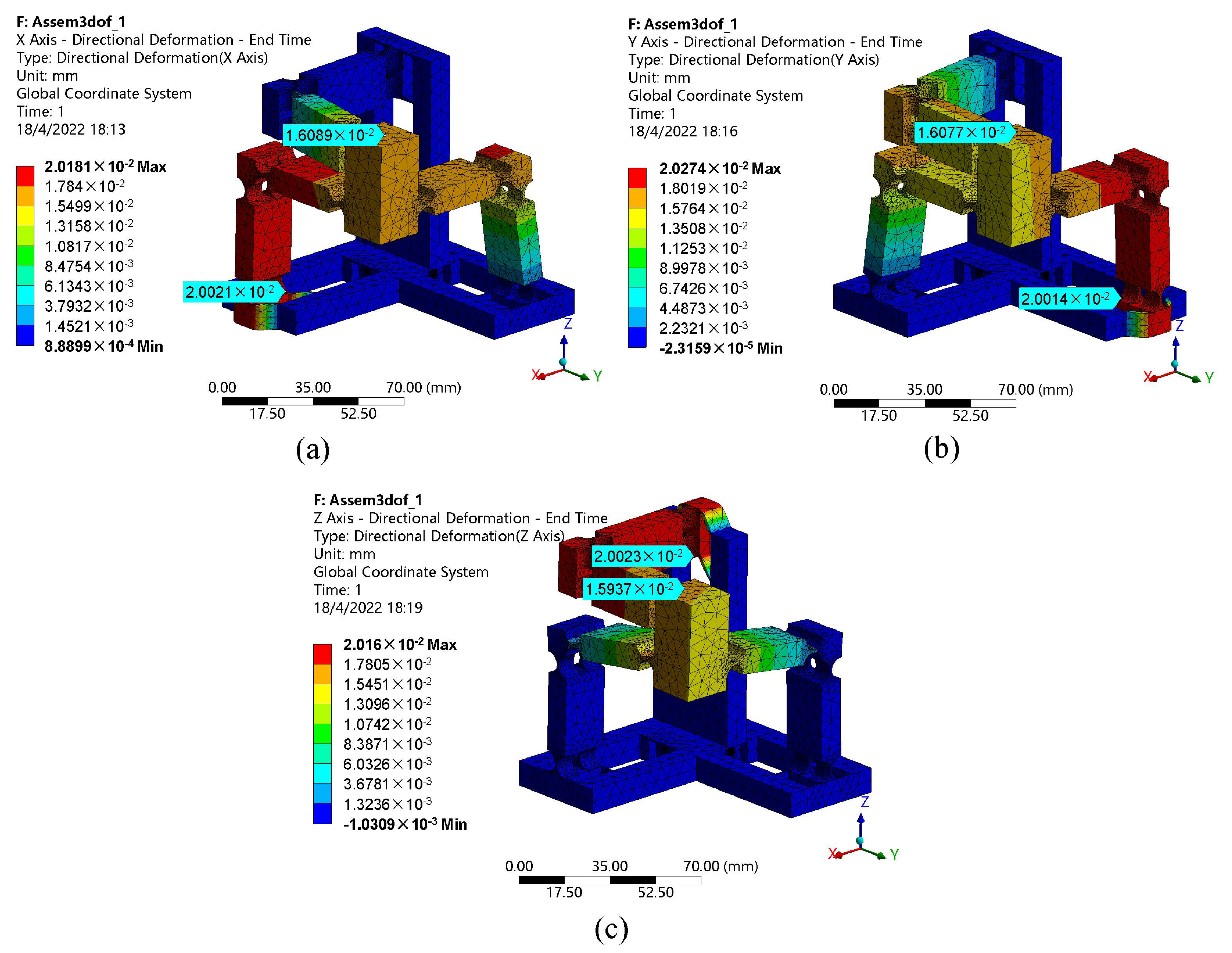
Figure 9 illustrates the output displacement of the motion platform with a 20 m input displacement on each axis. One can observe that the corresponding output displacement of the motion platform is 16 m with the same direction as the driving axis, which has a motion loss of 20%. The motion loss is mainly caused by the constraint of the passive legs and the deformation of the driving leg which is a cantilever structure. In the case of 20 m input, the deflection of the cantilever beam can be determined by and it is equal to 1 m, which is still smaller than the motion loss of 4 m. This deviation may be further linked to the following two reasons. Firstly, the right circular flexure hinge on the leg may increase the distortion of the structure. For the next reason is that the leg is fixed on the GM, and the GM is connected with the base frame using beam flexure hinges, which may also induce the distortion.
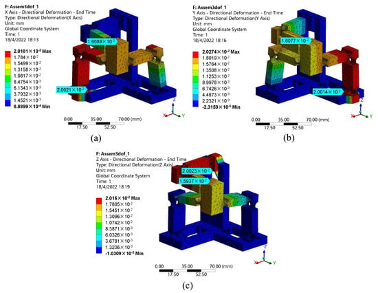
Figure 9.
The corresponding output displacement of the motion platform with a 20 m input on different axes: (a) x-axis, (b) y-axis, (c) z-axis.
The decoupling property of the compliant mechanism is depicted in Table 3. When the motion platform is driven toward x-axis with a displacement of 16, the cross-axis motions along the y and z axes are 1.4 and −0.84 m, respectively. A major motion along the y-axis induces the parasitic motions of 2.82 and −0.62 m along the x and z axes. Similarly, the couple motions along the x and y axes caused by the output displacement of 16 m in the z-axis are −0.96 and 1.41 m. The results reveal that the decoupling properties among all axes of the proposed mechanism are not as good as they should be, and it may be linked to the distortion of the driving legs.

Table 3.
Performance of the proposed triaxial compliant manipulator.
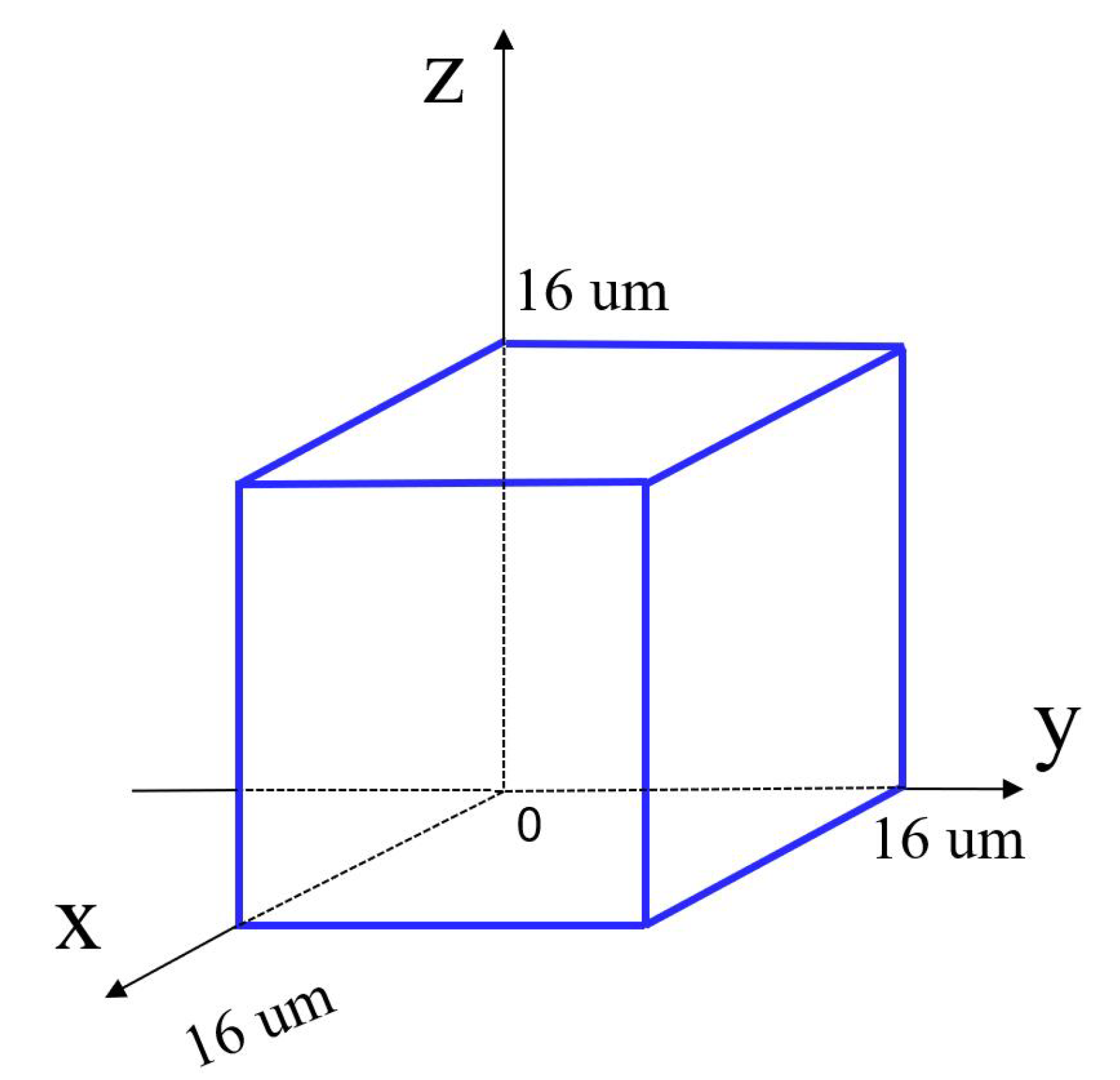
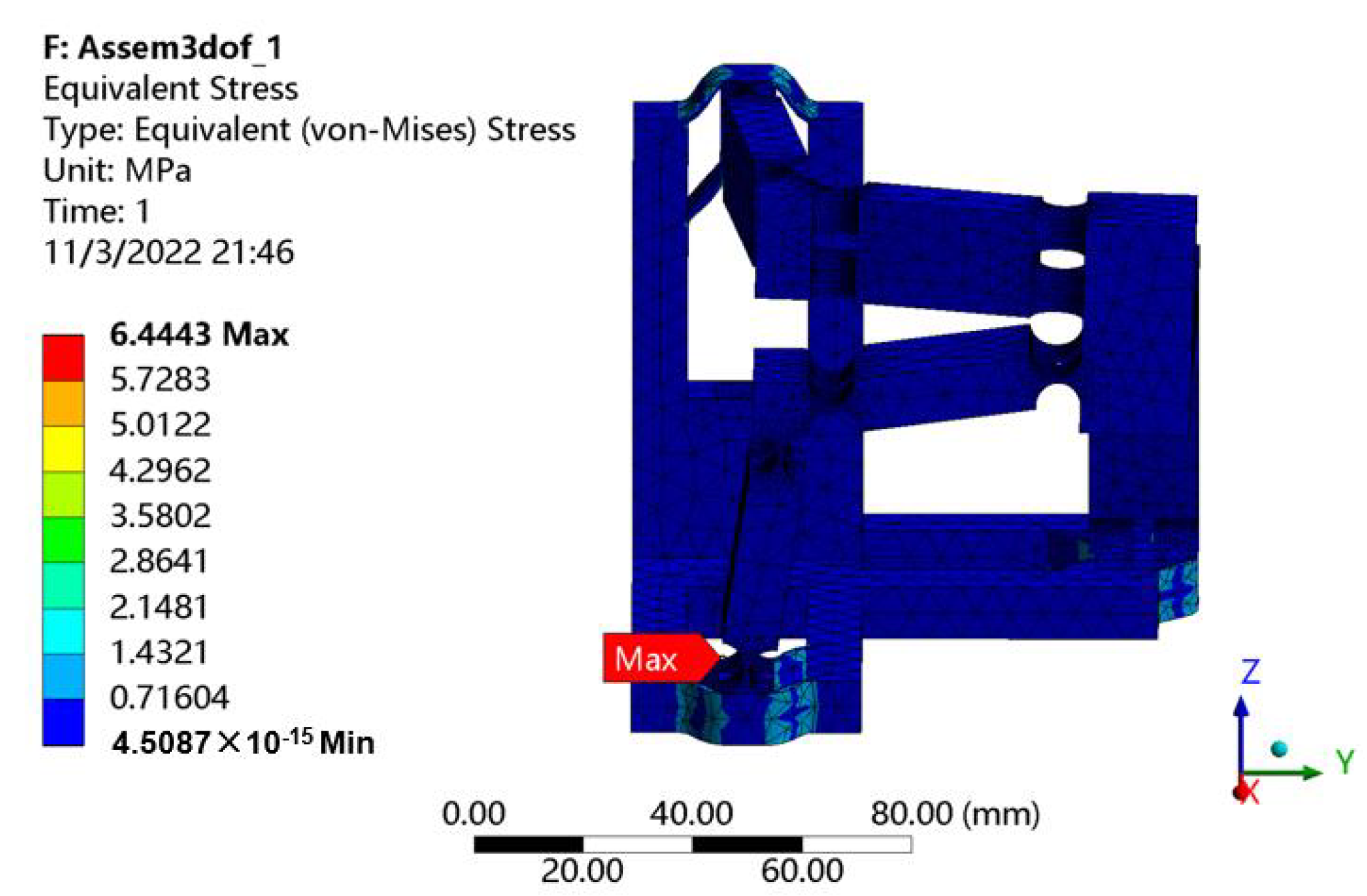
With the consideration of the maximum stroke of the selected PEA, the workspace of the mechanism can be obtained as shown in Figure 10. The reachable workspace is a cube with 16 m along each axis. In addition, the maximal stress of 6.44 MPa occurred in the beam flexure hinges can be observed from Figure 11 when the maximum stroke of 20 m of the PEA is exerted on the input end. It is much lower than the yield strength 50 MPa, indicating that the proposed mechanism is capable of working normally without failure.
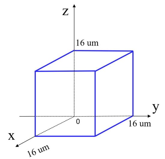
Figure 10.
The reachable workspace of the proposed triaxial compliant manipulator.
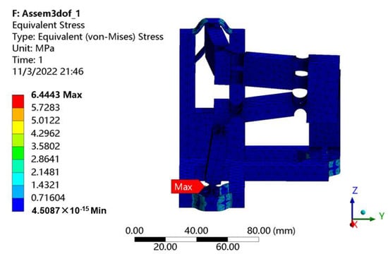
Figure 11.
Stress distribution.
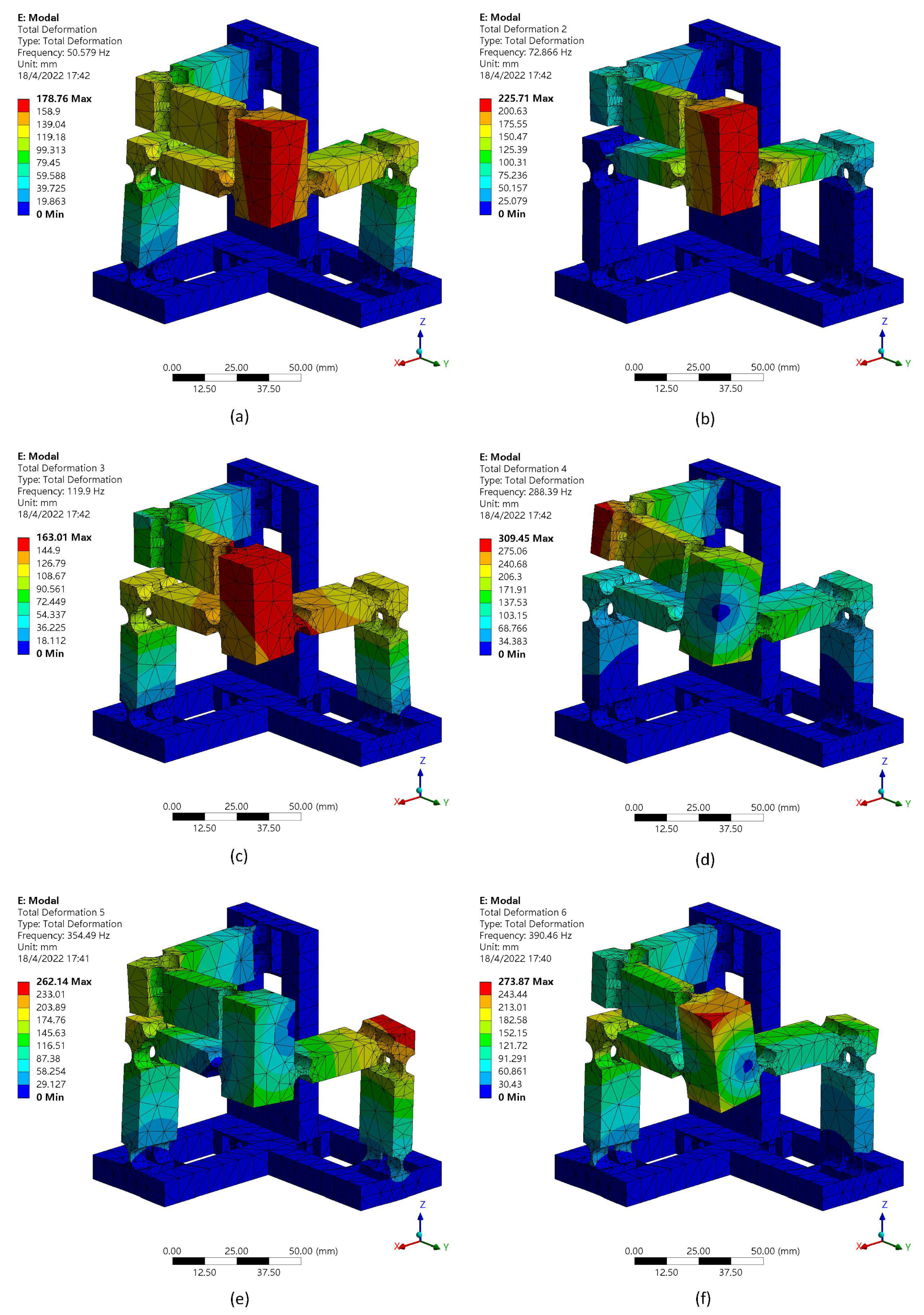
The dynamic performances are also studied with the FEA methodology. The first six mode shapes are shown in Figure 12. The first mode has a frequency of 50.58 Hz. The second and third modes of the proposed compliant mechanism have the frequencies of 72.87 Hz and 119.9 Hz, respectively. The corresponding value of the fourth, fifth, sixth modes are 288.39 Hz, 354.49 Hz and 390.46 Hz.
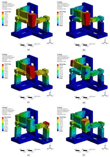
Figure 12.
First six mode shapes: (a) mode 1, (b) mode 2, (c) mode 3, (d) mode 4, (e) mode 5, (f) mode 6.
It can be observed that the first three resonance frequencies are different and the reasons are as follows. According to the working principle of the manipulator, when the motion platform moves toward x-axis, , and share the same displacement of the motion platform. However, and only have half of the displacement. When the motion platform moves toward y-axis, , , and share the same displacement of the motion platform. However, and only have half of the displacement. When the motion platform moves toward the z-axis, , share the same displacement of the motion platform. However, and only have half of the displacement. As a result, the equivalent masses in different directions are different, with the consideration of the same equivalent stiffness as given in Table 2, and thus the vibration modes have different resonance frequency values.
5. Conclusions
A novel triaxial parallel-kinematic compliant manipulator inspired by the Tripteron mechanism is proposed and analyzed in this paper. The manipulator is composed of a base structure, three legs and a motion platform. Unlike the design of most conventional triaxial compliant mechanisms, the base frames of the mechanisms were ignored. The proposed compliant manipulator has taken it into consideration in the design. Due to the unique configuration of the proposed manipulator, it is able to realize the triaxial translational motions with a compact structure. The assembly error can also be avoided by fabricating the mechanism monolithically with the help of 3D printing technology. The stiffness/compliance model of the mechanism is established based on the compliance matrix modeling method and verified by FEA simulations. The deviations between them are in a reasonable range. A cubic workspace with 16 m along each axis is observed with a maximum stress much lower than the yield strength, which means the manipulator is in safe working condition, although the decoupling performance is not as good as expected. In addition, the dynamic performances of the manipulator are also indicated via the simulations. In the future research, 3D printing technology is expected to fabricate the prototype to experimentally study the comprehensive performances of the proposed manipulator.
Author Contributions
Y.X. established the model of the compliant mechanism and performed simulations to verify it; Y.X. also wrote the original draft; Y.L. provided the guidance of the mechanism design, and contributed to reviewing as well as editing the manuscript; C.C. conducted careful reviewing and revision of the manuscript. All authors have read and agreed to the published version of the manuscript.
Funding
This research was funded by the National Natural Science Foundation of China (Grant No. 51575544).
Institutional Review Board Statement
Not applicable.
Informed Consent Statement
Not applicable.
Data Availability Statement
Not applicable.
Acknowledgments
The authors would like to express their sincere thanks for the financial support from the State Key Laboratory of Ultra-precision Machining Technology of The Hong Kong Polytechnic University(BBXG) and a grant from the Research Committee of The Hong Kong Polytechnic University under the student account code RK34.
Conflicts of Interest
The authors declare no conflict of interest.
References
- Fleming, A.J.; Aphale, S.S.; Moheimani, S.R. A new method for robust damping and tracking control of scanning probe microscope positioning stages. IEEE Trans. Nanotechnol. 2009, 9, 438–448. [Google Scholar] [CrossRef]
- Komati, B.; Clévy, C.; Lutz, P. High bandwidth microgripper with integrated force sensors and position estimation for the grasp of multistiffness microcomponents. IEEE/ASME Trans. Mechatron. 2016, 21, 2039–2049. [Google Scholar] [CrossRef] [Green Version]
- Wang, G.; Xu, Q. Design and precision position/force control of a piezo-driven microinjection system. IEEE/ASME Trans. Mechatron. 2017, 22, 1744–1754. [Google Scholar] [CrossRef]
- Wang, F.; Huo, Z.; Liang, C.; Shi, B.; Tian, Y.; Zhao, X.; Zhang, D. A novel actuator-internal micro/nano positioning stage with an arch-shape bridge-type amplifier. IEEE Trans. Ind. Electron. 2018, 66, 9161–9172. [Google Scholar] [CrossRef] [Green Version]
- Wang, D.; Yang, Q.; Dong, H. A monolithic compliant piezoelectric-driven microgripper: Design, modeling, and testing. IEEE/ASmE Trans. Mechatron. 2011, 18, 138–147. [Google Scholar] [CrossRef]
- Wu, S.; Shao, Z.; Su, H.; Fu, H. An energy-based approach for kinetostatic modeling of general compliant mechanisms. Mech. Mach. Theory 2019, 142, 103588. [Google Scholar] [CrossRef]
- Yang, X.; Zhu, L.; Li, S.; Zhu, W.; Ji, C. Development of a Novel pile-up Structure based nanopositioning mechanism driven by piezoelectric actuator. IEEE/ASME Trans. Mechatron. 2020, 25, 502–512. [Google Scholar] [CrossRef]
- Gao, X.; Liu, Y.; Zhang, S.; Deng, J.; Liu, J. Development of a novel flexure-based XY platform using single bending hybrid piezoelectric actuator. IEEE/ASME Trans. Mechatron. 2022, 1–11. [Google Scholar] [CrossRef]
- Liang, C.; Wang, F.; Huo, Z.; Shi, B.; Tian, Y.; Zhao, X.; Zhang, D. A 2-DOF monolithic compliant rotation platform driven by piezoelectric actuators. IEEE Trans. Ind. Electron. 2019, 67, 6963–6974. [Google Scholar] [CrossRef]
- Gao, X.; Zhang, S.; Deng, J.; Liu, Y. Development of a small two-dimensional robotic spherical joint using a bonded-type piezoelectric actuator. IEEE Trans. Ind. Electron. 2019, 68, 724–733. [Google Scholar] [CrossRef]
- Yang, X.; Zhu, W.L.; Zhu, Z.; Zhu, L.M. Design, assessment, and trajectory control of a novel decoupled robotic nanomanipulator. IEEE/ASME Trans. Mechatron. 2022, 1–12. [Google Scholar] [CrossRef]
- Mitrovic, A.; Nagel, W.S.; Leang, K.K.; Clayton, G.M. Closed-loop range-based control of dual-stage nanopositioning systems. IEEE/ASME Trans. Mechatron. 2020, 26, 1412–1421. [Google Scholar] [CrossRef]
- Hao, G.; Zhu, J. Design of a monolithic double-slider based compliant gripper with large displacement and anti-buckling ability. Micromachines 2019, 10, 665. [Google Scholar] [CrossRef] [Green Version]
- Wadikhaye, S.; Yong, Y.; Moheimani, S.R. Design of a compact serial-kinematic scanner for high-speed atomic force microscopy: An analytical approach. Micro Nano Lett. 2012, 7, 309–313. [Google Scholar] [CrossRef] [Green Version]
- Kenton, B.J.; Leang, K.K. Design and control of a three-axis serial-kinematic high-bandwidth nanopositioner. IEEE/ASME Trans. Mechatron. 2011, 17, 356–369. [Google Scholar] [CrossRef]
- Liu, Y.T.; Li, B.J. A 3-axis precision positioning device using PZT actuators with low interference motions. Precis. Eng. 2016, 46, 118–128. [Google Scholar] [CrossRef]
- Xiao, R.; Shao, S.; Xu, M.; Jing, Z. Design and analysis of a novel piezo-actuated XYθz micropositioning mechanism with large travel and kinematic decoupling. Adv. Mater. Sci. Eng. 2019. [Google Scholar] [CrossRef] [Green Version]
- Muraoka, M.; Sanada, S. Displacement amplifier for piezoelectric actuator based on honeycomb link mechanism. Sens. Actuators A Phys. 2010, 157, 84–90. [Google Scholar] [CrossRef]
- Li, Y.; Xu, Q. A totally decoupled piezo-driven XYZ flexure parallel micropositioning stage for micro/nanomanipulation. IEEE Trans. Autom. Sci. Eng. 2010, 8, 265–279. [Google Scholar] [CrossRef]
- Zhu, Z.; To, S.; Zhu, W.L.; Li, Y.; Huang, P. Optimum design of a piezo-actuated triaxial compliant mechanism for nanocutting. IEEE Trans. Ind. Electron. 2017, 65, 6362–6371. [Google Scholar] [CrossRef]
- Gao, J.; Zeng, Z.; Tang, H.; Chen, X.; Qiu, Q.; He, S.; He, Y.; Yang, Z. Design and assessment of a piezo-actuated 3-DOF flexible nanopositioner with large stroke. In Proceedings of the 2016 IEEE International Conference on Manipulation, Manufacturing and Measurement on the Nanoscale (3M-NANO), Chongqing, China, 18–22 July 2016; pp. 19–24. [Google Scholar]
- Bacher, J.P.; Bottinelli, S.; Breguet, J.M.; Clavel, R. Delta3: Design and control of a flexure hinge mechanism. In Microrobotics and Microassembly III, Proceedings of the Intelligent Systems and Advanced Manufacturing, Boston, MA, USA, 28–31 October 2001; SPIE: Bellingham, WA, USA, 2001; Volume 4568, pp. 135–142. [Google Scholar]
- Tang, X.; Chen, I.M.; Li, Q. Design and nonlinear modeling of a large-displacement XYZ flexure parallel mechanism with decoupled kinematic structure. Rev. Sci. Instruments 2006, 77, 115101. [Google Scholar] [CrossRef]
- Hao, G.; Kong, X. A 3-DOF translational compliant parallel manipulator based on flexure motion. In Proceedings of the ASME International Design Engineering Technical Conferences and Computers and Information in Engineering Conference, San Diego, CA, USA, 30 August–2 September 2009; Volume 49040, pp. 101–110. [Google Scholar]
- Hao, G.; Kong, X. Design and modeling of a large-range modular XYZ compliant parallel manipulator using identical spatial modules. ASME J. Mech. Robot. 2012, 4, 021009. [Google Scholar] [CrossRef]
- Awtar, S.; Ustick, J.; Sen, S. An XYZ parallel-kinematic flexure mechanism with geometrically decoupled degrees of freedom. ASME J. Mech. Robot. 2013, 5, 015001. [Google Scholar] [CrossRef]
- Awtar, S.; Quint, J.; Ustick, J. Experimental characterization of a large-range parallel kinematic XYZ flexure mechanism. ASME J. Mech. Robot. 2021, 13, 015001. [Google Scholar] [CrossRef]
- Gallego, J.A.; Herder, J. Synthesis methods in compliant mechanisms: An overview. In Proceedings of the ASME International Design Engineering Technical Conferences and Computers and Information in Engineering Conference, San Diego, CA, USA, 30 August–2 September 2009; Volume 49040, pp. 193–214. [Google Scholar]
- Sigmund, O. On the design of compliant mechanisms using topology optimization. J. Struct. Mech. 1997, 25, 493–524. [Google Scholar] [CrossRef]
- Kumar, P.; Schmidleithner, C.; Larsen, N.; Sigmund, O. Topology optimization and 3D printing of large deformation compliant mechanisms for straining biological tissues. Struct. Multidiscip. Optim. 2021, 63, 1351–1366. [Google Scholar] [CrossRef]
- Kong, X.; Gosselin, C.M. Kinematics and singularity analysis of a novel type of 3-CRR 3-DOF translational parallel manipulator. Int. J. Robot. Res. 2002, 21, 791–798. [Google Scholar] [CrossRef]
- Gosselin, C.; Kong, X.; Foucault, S.; Bonev, I. A fully decoupled 3-dof translational parallel mechanism. In Proceedings of the 4th Chemnitz Parallel Kinematics Seminar, Chemnitz, Germany, 20–21 April 2004; pp. 595–610. [Google Scholar]
- Quennouelle, C.; Gosselin, C. Kinematostatic modeling of compliant parallel mechanisms. Meccanica 2011, 46, 155–169. [Google Scholar] [CrossRef]
- Ling, M.; Howell, L.L.; Cao, J.; Chen, G. Kinetostatic and dynamic modeling of flexure-based compliant mechanisms: A survey. Appl. Mech. Rev. 2020, 72, 030802. [Google Scholar] [CrossRef] [Green Version]
- Bilancia, P.; Berselli, G. An overview of procedures and tools for designing nonstandard beam-based compliant mechanisms. Comput.-Aided Des. 2021, 134, 103001. [Google Scholar] [CrossRef]
- Ling, M.; Song, D.; Zhang, X.; He, X.; Li, H.; Wu, M.; Cao, L.; Lu, S. Analysis and design of spatial compliant mechanisms using a 3-D dynamic stiffness model. Mech. Mach. Theory 2022, 168, 104581. [Google Scholar] [CrossRef]
- Howell, L.L.; Magleby, S.P.; Olsen, B.M. Handbook of Compliant Mechanisms; John Wiley & Sons Incorporated: Hoboken, NJ, USA, 2013; p. 311. [Google Scholar]
- Xie, Y.; Li, Y.; Cheung, C.F.; Zhu, Z.; Chen, X. Design and analysis of a novel compact XYZ parallel precision positioning stage. Microsyst. Technol. 2021, 27, 1925–1932. [Google Scholar] [CrossRef]
- Chen, X.; Li, Y. Design and analysis of a new high precision decoupled XY compact parallel micromanipulator. Micromachines 2017, 8, 82. [Google Scholar] [CrossRef]
- Koseki, Y.; Tanikawa, T.; Koyachi, N.; Arai, T. Kinematic analysis of a translational 3-dof micro-parallel mechanism using the matrix method. Adv. Robot. 2002, 16, 251–264. [Google Scholar] [CrossRef]
- Moritoki, Y.; Furukawa, T.; Sun, J.; Yokoyama, M.; Shimono, T.; Yamada, T.; Nishiwaki, S.; Kageyama, T.; Fukuda, J.; Mukai, M.; et al. 3D-printed micro-tweezers with a compliant mechanism designed using topology optimization. Micromachines 2021, 12, 579. [Google Scholar] [CrossRef] [PubMed]
- Li, X.; Yu, D.; Cao, T.; Wen, Z.; Lu, C.; Liu, W.; Zhu, C.; Wu, D. 3D printing and dynamic modeling of a polymer-based bimodal piezoelectric motor. Smart Mater. Struct. 2020, 30, 025003. [Google Scholar] [CrossRef]
- Clark, L.; Shirinzadeh, B.; Bhagat, U.; Smith, J.; Zhong, Y. Development and control of a two DOF linear–angular precision positioning stage. Mechatronics 2015, 32, 34–43. [Google Scholar] [CrossRef]
Publisher’s Note: MDPI stays neutral with regard to jurisdictional claims in published maps and institutional affiliations. |
© 2022 by the authors. Licensee MDPI, Basel, Switzerland. This article is an open access article distributed under the terms and conditions of the Creative Commons Attribution (CC BY) license (https://creativecommons.org/licenses/by/4.0/).

