Article

Electrolessly Deposited Carbon-Supported CuNiSn Electrocatalysts for the Electrochemical Reduction of CO2

1
Department of Chemical Engineering, Faculty of Engineering and Industrial Technology, Silpakorn University, Nakorn Pathom 73000, Thailand
2
Center of Excellence on Catalysis and Catalytic Reaction Engineering, Department of Chemical Engineering, Faculty of Engineering, Chulalongkorn University, Bangkok 10330, Thailand
*
Author to whom correspondence should be addressed.
Catalysts 2023, 13(6), 1020; https://doi.org/10.3390/catal13061020
Submission received: 4 March 2023 / Revised: 29 May 2023 / Accepted: 7 June 2023 / Published: 19 June 2023
(This article belongs to the Special Issue Heterogeneous Electrocatalysts for CO2 Reduction)

Abstract

:
Aiming at developing low-cost, high-performance catalysts for the electrochemical reduction of CO2 (CO2-ERR) to valuable multicarbon (C2–C3) chemicals to alleviate global warming, trimetallic alloy electrocatalysts containing Cu, Ni, and Sn supported on a Pd-activated carbon fabric substrate (CS) were prepared via an electroless deposition method. The as-deposited CuNiSn/CS electrocatalysts were employed in CO2-ERR in an H-cell type reactor at an applied potential of −1.6 V vs. Ag/AgCl. The effect of the electroless deposition time (15, 30, and 45 min) was investigated, finding no significant structural differences according to the X-ray diffraction patterns. The evaluation of the reaction performance via linear sweep voltammetry revealed that CO2 was more effectively reduced to adsorbed species on the catalytic surface sites of the electrocatalyst prepared with a 30 min deposition time. The analysis of the gas and liquid products via gas chromatography and nuclear magnetic resonance, respectively, revealed that the Faradaic efficiency and H2 production over CuNiSn/CS was lower than those over related bimetallic and monometallic electrocatalysts, indicating the inhibition of the competitive H2 evolution reaction. Liquid products including formate, ethylene glycol, acetone, ethanol, acetate, and 1-buthanol were detected.

1. Introduction

The increasing concentration of carbon dioxide (CO2) in the atmosphere caused by the massive consumption of fossil fuels has caused the phenomenon of global warming, which is known as “the greenhouse effect” [1]. To address the global issue of increasing CO2 emissions, the CO2 reduction reaction (CO2-RR) is considered an efficient approach. Additionally, CO2-RR affords products that can be used as raw materials and intermediates in several chemical processes [1,2,3]. For example, CO can be mixed with H2 (syngas) to produce hydrocarbons. For the final products of CO2-RR in liquid phase, formate is used as a reducing agent. Methanol and ethanol are used as transport fuels or solvents. Among the methods that have been investigated to reduce the negative effect of the increasing CO2 concentration in the atmosphere, including chemical, biological, photochemical, and electrochemical methods [4], electrochemical CO2-RR (CO2-ERR) is particularly attractive because it can be operated at room temperature and atmospheric pressure and the reaction rate and product selectivity can be controlled by an appropriate selection of metals, electrolytes, and redox potentials.
Using a highly effective electrode has been suggested as a key factor affecting the electrochemical performance when employing solid catalysts. Several studies have reported the use of transition metal compounds by combining multimetal compounds to generate multiple active sites that can function during the reactions [5,6]. For instance, Poudel et al. reported that Co-Al-LDH@Fe2O3/3DPCNF catalysts were effective for Cr(VI) and Pb(II) [7] removal. For CO2-ERR, such catalysts favor CO2 adsorption on the catalytic surface.
In this context, copper (Cu) has attracted great attention because hydrocarbons, aldehydes, and alcohols can be produced on this metal at high current densities. However, Cu electrodes exhibit low product selectivity due to weak CO2 adsorption on the catalytic surface. Therefore, Cu electrodes have been modified with other metals, including nickel (Ni), silver (Ag), titanium (Ti), tin (Sn), and bismuth (Bi), to create a synergistic effect that improves their physicochemical properties.
The resulting modified electrodes show great catalytic potential, favor CO2 adsorption, and are less expensive than noble metals. For instance, Jeon et al. [8] synthesized an Ag–Cu bimetallic electrode for CO2-ERR with improved carbon monoxide (CO) Faradaic efficiency (FE) from 29.8% to 39.6% compared with Cu nanowires. Furthermore, Ke Ye et al. [9] demonstrated a novel strategy for designing a Sn/Cu alloy catalyst for CO2-RR using a decorated coelectrode position method to achieve high performance in the production of formate. The Sn–Cu alloy exhibited an FE of 82.3% at −1.14 V vs. RHE, inhibited hydrogen (H2) and CO evolution, and promoted formate production. Tomiko M. Suzuki et al. [10] used an oxidized Cu–Ni intermetallic alloy for CO2-ERR. The product selectivity was highly dependent on the initial Ni composition and the FE for ethylene and ethanol production was improved by adding a small amount of Ni.
In this study, to demonstrate the feasibility of using a trimetallic catalyst for CO2-ERR, a Cu–Ni–Sn electrocatalyst (CuNiSn) supported on a carbon fabric was prepared via an electroless deposition method. This preparation does not require an external power source because the reductant acts as an electron donor to reduce the metal ions. Additionally, the interested metal is deposited on only chosen portions, and metal deposition can be controlled through the deposition time. Furthermore, the substrates are simply immersed in an aqueous solution; thus, no advanced equipment is required. Therefore, this technique is inexpensive compared to the metal chemical vapor deposition and electrodeposition methods. The effect of metal deposition time (15, 30, and 45 min) on the structure and performance of the catalyst was studied. In addition, the reaction performance of the trimetallic electrocatalyst was compared with that of bimetallic and monometallic derivatives. Finally, the electrochemical stability of the electrocatalysts was determined using chronoamperometry. The electrolessly deposited CuNiSn electrocatalyst was found to be active and effective for CO2-ERR. Overall, this work provides new insights into using low-cost non-noble electrocatalysts prepared via a simple electroless deposition method to convert CO2 to valuable multicarbon (C2–C3) chemicals.

2. Results and Discussion

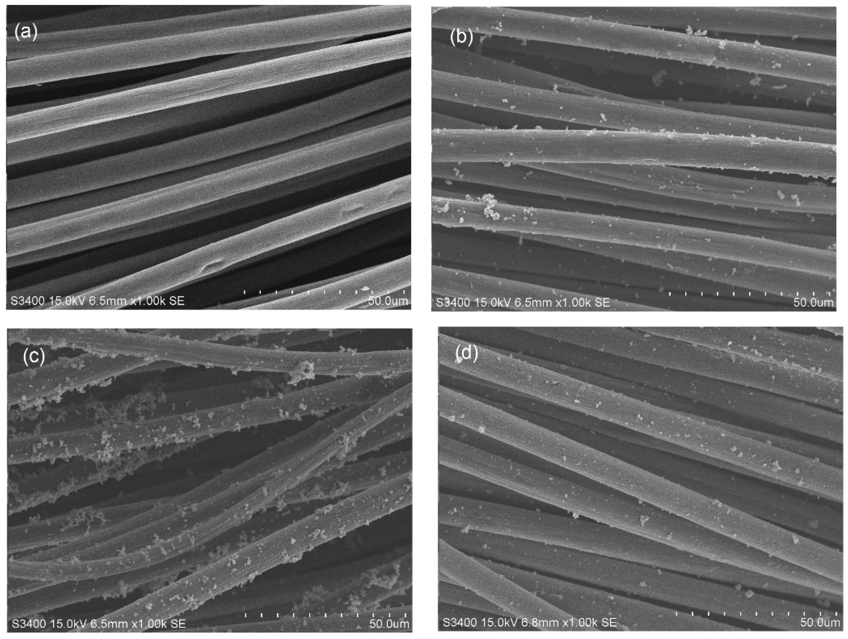
2.1. Effect of Electroless Deposition Time on the Structure of CuNiSn/CS Electrocatalysts

The structure of the CuNiSn/CS_15, CuNiSn/CS_30, and CuNiSn/CS_45 electrocatalysts was investigated using X-ray diffraction (XRD). The corresponding patterns are shown in Figure 1. Peaks indicating the formation of a Cu/Ni alloy on CS were observed at 2θ = 43.5° and 50°. In addition, the formation of Ni was observed at 54°. However, peaks corresponding to Sn were not detected, probably due to the small amount of Sn deposited on the surface. No significant difference was observed in the XRD patterns of the three samples. Thus, the deposition time had little effect on the crystalline structure of the catalysts. Representative scanning electron microscopy (SEM) images of the electrocatalysts synthesized via electroless deposition are displayed in Figure 2. Inactivated carbon has a smooth cylindrical structure (Figure 2a), which was covered by a thin film, with some spherical and nonuniform particles deposited on the surface after electroless deposition (Figure 2b–d). A high number of deposited metal particles were observed for CuNiSn/CS_30 (Figure 2c).
Table 1 summarizes the results of the ICP analysis. Cu was the main species deposited on the surface. When the deposition time was increased from 15 to 45 min, the amount of deposited Cu increased; however, no further increase was observed beyond 30 min of deposition time for Ni and Sn. Generally, the number of metal particles increased with increasing deposition time. However, the decrease in Ni and Sn particles was observed probably because a reverse reaction caused the etching of deposited particles, and the impoverishment of ions including nickel and tin ions in the electroless bath occurred. Additionally, low Sn content was detected because a small amount of SnSO4 was used.

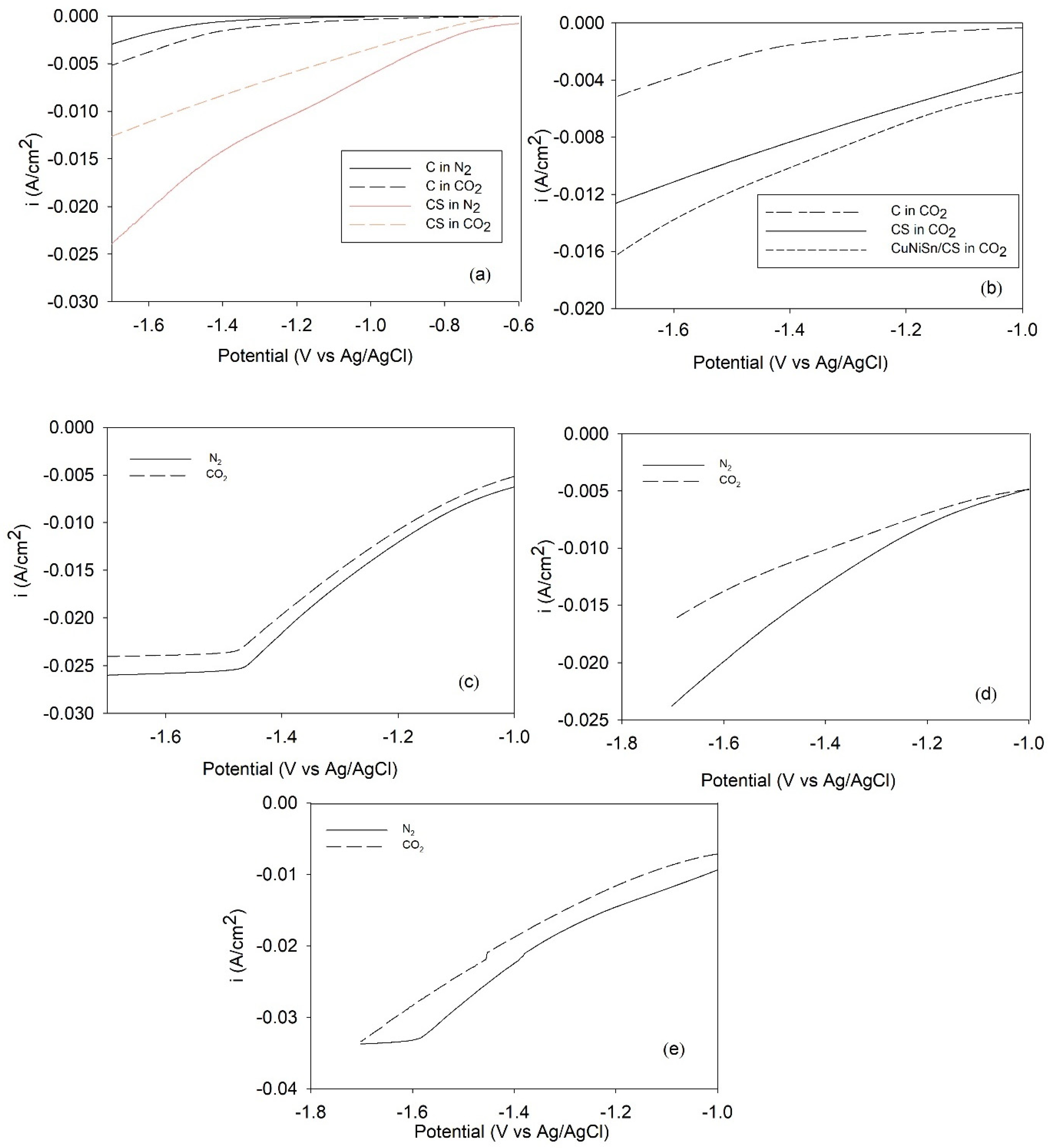
2.2. Effect of the Electroless Deposition Time on the CO2-ERR Performance of the CuNiSn/CS Electrocatalysts

Next, the CO2-ERR performance over plain carbon (C), CS, CuNiSn/CS_15, CuNiSn/CS_30, and CuNiSn/CS_45 was evaluated via Linear sweep voltammetry (LSV) analysis. The current curves at the most negative potentials were monitored in the base electrolyte following 20 min of CO2 saturation.
Plain carbon was not active in the H2 evolution reaction (HER) and CO2-ERR because it showed low current density (Figure 3a). For CS, the current was increased for all negative potentials in the HER and CO2-ERR (Figure 3a). Generally, Pd is active for CO2-ERR, especially for the HER. In this study, Pd was used as an initiator of the electroless plating. However, after depositing metals on CS, the current increased for all negative potentials in CO2-ERR (Figure 3b). Thus, the CO2-ERR on CuNiSn/CS can be attributed to the deposited metals (Cu, Ni, and Sn).
For CuNiSn/CS_15, CuNiSn/CS_30, and CuNiSn/CS_45 (Figure 3c–e), in the absence of CO2 (dotted curve), currents below −1.00 V vs. Ag/AgCl are associated with H2 formation. The reductive current increased with increasing potential. However, under CO2 saturation (black curves), the current stems from both the H2 evolution reaction (HER) and CO2-ERR. The result showed that the current was suppressed for all negative potentials, suggesting that the intermediates of CO2-ERR bound to the sites that would otherwise be active for the HER.
The electrocatalysts under study behaved similarly in the presence of CO2. The cathodic current decreased at potentials lower than −1.0 V vs. Ag/AgCl, which can be attributed to the inhibition of the HER due to the adsorption of species derived from CO2 reduction, such as CO and formate [11]. In addition, the gap between the black and dotted curves for CuNiSn/CS_30 (Figure 3d) was larger than that for CuNiSn/CS_45 and CuNiSn/CS_15 (Figure 3c,e), implying that CO2 effectively reduced to adsorbed species on the catalytic surface sites of CuNiSn/CS_30 [12]. In addition, CuNiSn/CS_15 in CO2 and N2 and CuNiSn_45 in N2 reached steady current densities at negative potentials, probably due to the difference in the surface morphologies of the deposited metals. The reasons for this feature remain unclear and are out of the scope of this study, so it should be investigated in future studies. A current plateau in LSV analysis has been reported in previous studies [13,14].

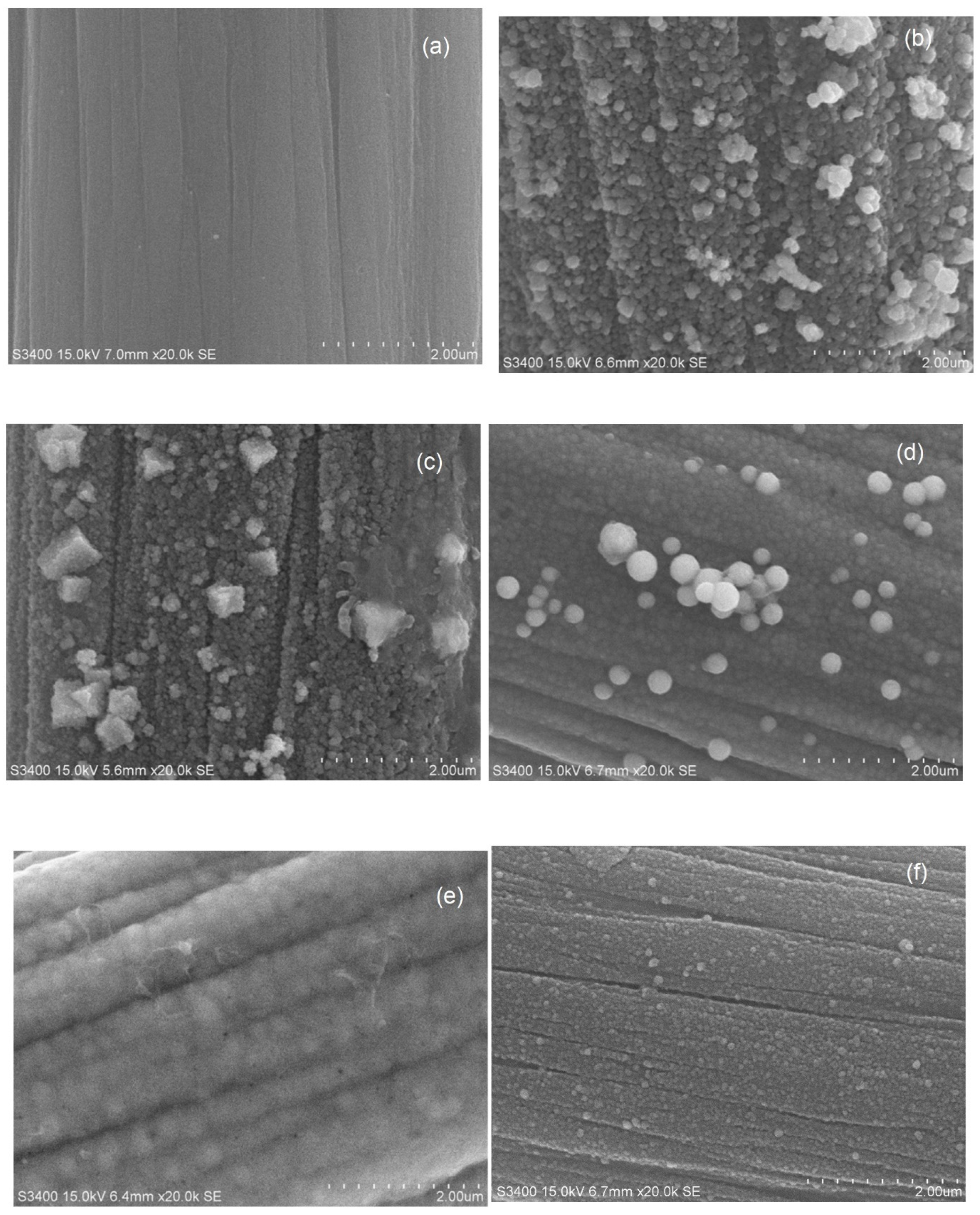
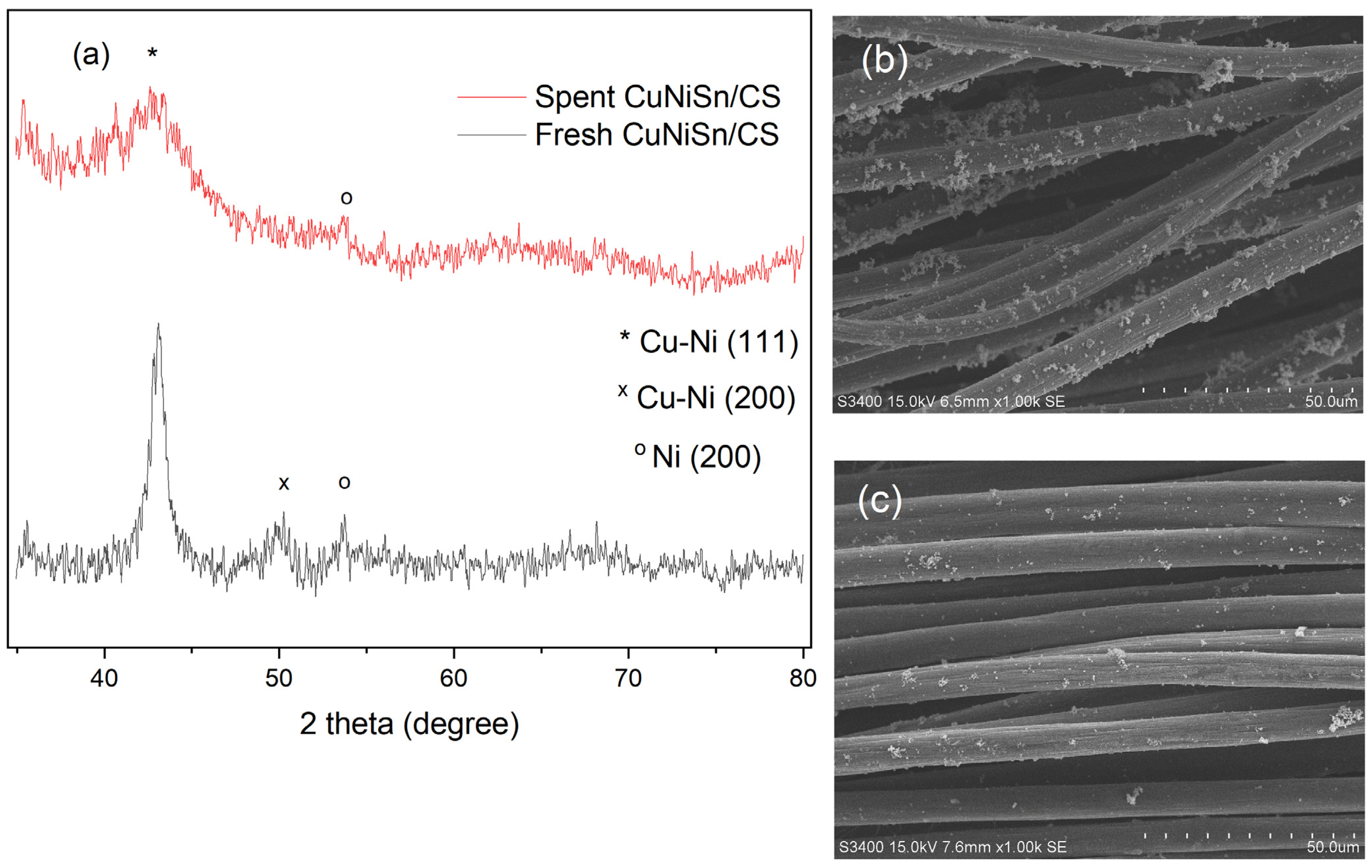
2.3. SEM–EDX Analysis of Tri-, Bi-, and Monometallic Alloy Electrocatalysts

Figure 4 displays representative SEM images of the tri-, bi-, and monometallic electrocatalysts synthesized using an electroless deposition time of 30 min. The clean surface and cylindrical structure of CS (Figure 4a) were covered by spherical, nonuniformly dispersed particles after deposition (Figure 4b,c,f, for CuNiSn/CS, CuNi/CS, and Cu/CS, respectively). For the NiSn/CS and Ni/CS electrocatalysts (Figure 4d,e), the Ni layer on the surface of the carbon fabric was uniform and compact, with no scattered Ni particles on the coating surface, suggesting that Ni was mainly deposited on the surface of the carbon fabric. SEM images of electrocatalysts with a lower magnification are displayed in Figure S1.
The element distribution on the carbon fabric is shown in Table 1. In Cu-based electrocatalysts (CuNiSn/CS, CuSn/CS, and CuNi/CS), Cu was the main species, and small amounts of deposited Ni and Sn were observed. This suggests that Cu was reduced by both reducing agents, i.e., sodium hypophosphite monohydrate and formaldehyde, whereas Ni was reduced only by sodium hypophosphite monohydrate [15]. In the Ni-based NiSn/CS electrocatalyst, Ni was the main species because Ni and Sn could be reduced by sodium hypophosphite monohydrate. Due to the small amount of Sn precursor (SnSO4), a trace amount of deposited Sn was observed. Finally, Cu and Ni were deposited on the carbon surface of the monometallic Cu/CS and Ni/CS electrocatalysts, respectively.

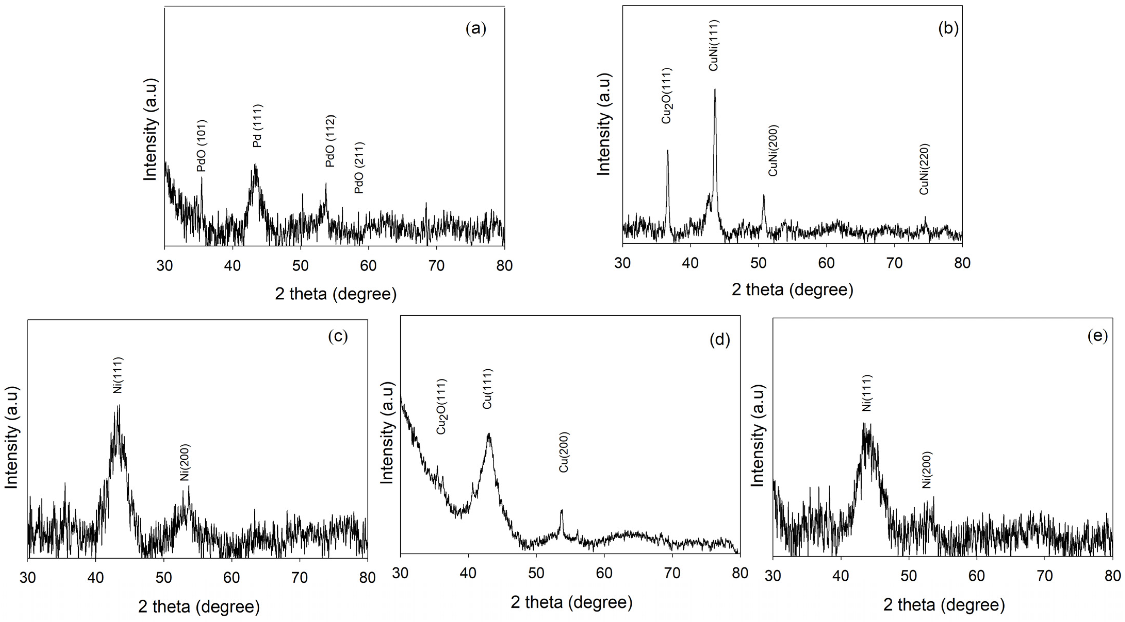
2.4. XRD Analysis of Tri-, Bi-, and Monometallic Alloy Electrocatalysts

The structure of electrocatalysts was further investigated using XRD (Figure 5a–e). The corresponding patterns showed an amorphous phase. The XRD of CS (Figure 5a) showed peaks at 2θ = 33°, 55°, and 61°, which are ascribed to PdO, and a peak at 40.1°, which is attributed to Pd [16]. Considering the bimetallic alloy electrocatalysts, the peaks in the CuNi/CS XRD pattern (Figure 5b) at 2θ = 43° and 50° indicate the formation of Cu/Ni [17,18] and the peak at 2θ = 36° indicates the formation of Cu2O [19]. The XRD pattern of NiSn/CS (Figure 5c) showed peaks at 2θ = 44° and 54°, corresponding to Ni [20]. Meanwhile, the monometallic Cu/CS electrocatalyst showed peaks at 2θ = 43°, 53°, and 75° (Figure 5d), similar to those of CuNi/CS, thereby indicating that Cu was formed [17]. Finally, the XRD pattern of Ni/CS (Figure 5e) showed peaks at 44° and 54° due to Ni [20], as in the XRD pattern of NiSn/CS. Moreover, peaks corresponding to Sn were not observed.

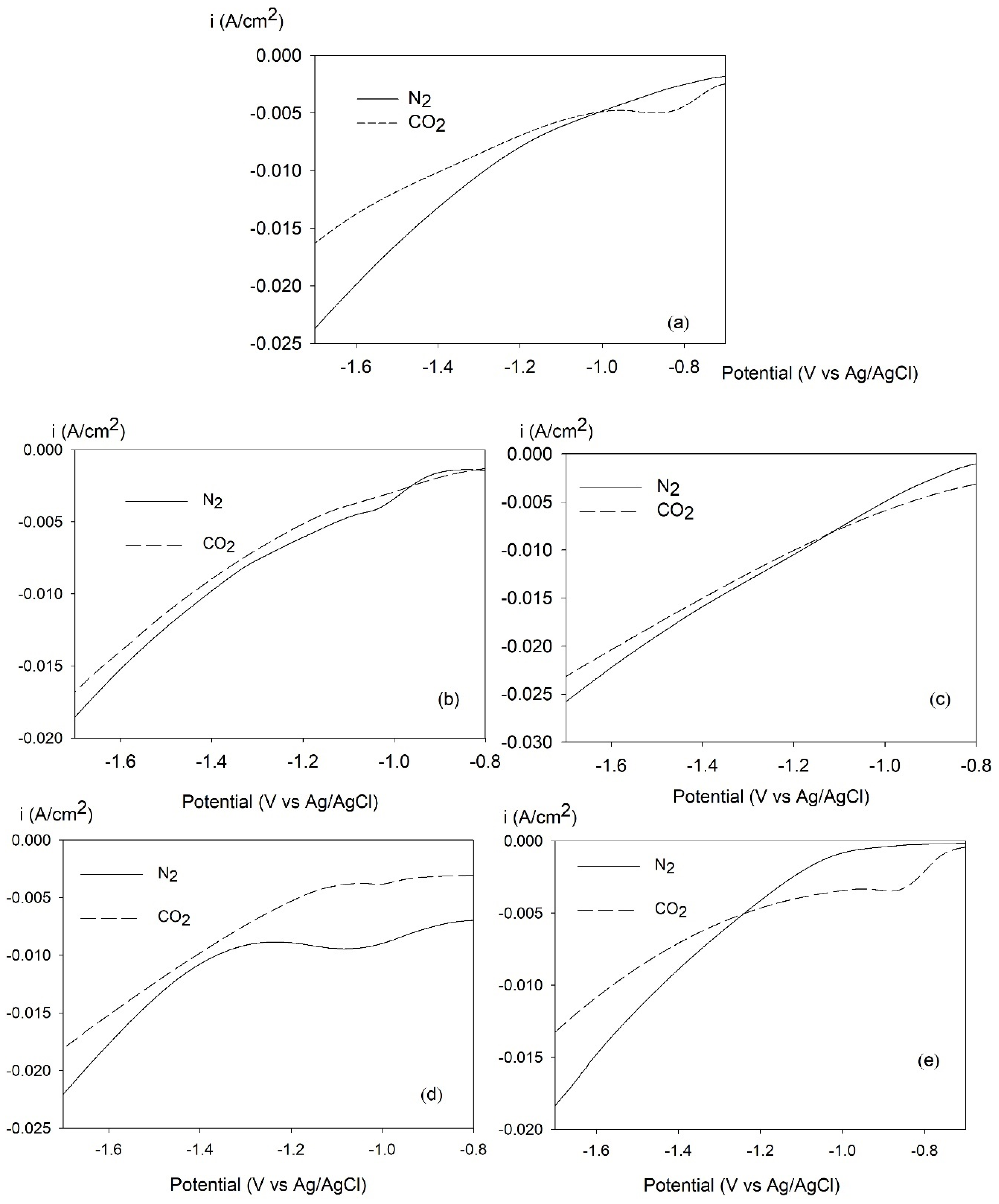
2.5. LSV for CO2-ERR over Tri-, Bi-, and Monometallic Alloy Electrocatalysts
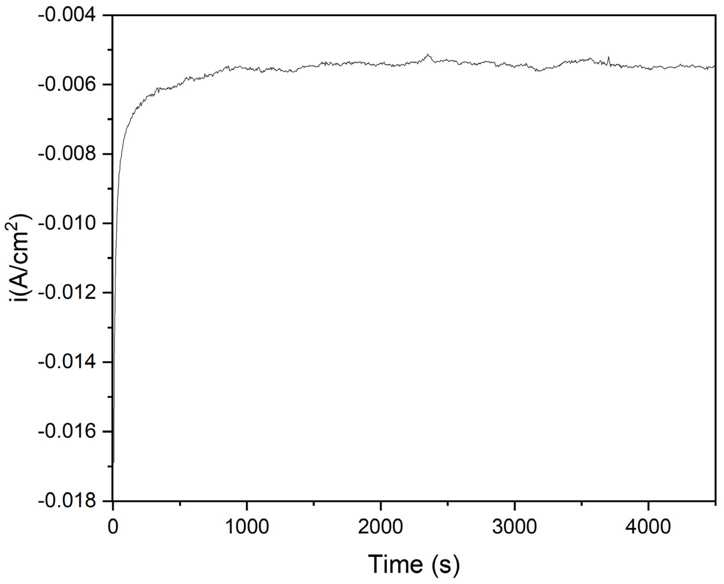
To compare the performance of tri-, bi-, and monometallic alloy electrocatalysts in CO2-ERR, LSV measurements were performed under nitrogen (N2)- and CO2-saturated solutions. In Figure 6a–e, the black and dotted black curves correspond to the rate of the HER and the rate of CO2-ERR, respectively. For CuNiSn/CS (Figure 6a), CuNi/CS (Figure 6b), and Cu/CS (Figure 6d), the current was suppressed at negative potentials under the CO2 saturation condition. However, CuNi/CS, NiSn/CS, and Ni/CS showed a small decrease in the current at negative potentials, suggesting that the intermediates of CO2-ERR might not bind to all the sites, which would still be available for the HER.
The CuNiSn/CS and Cu/CS electrocatalysts behaved similarly in the presence of CO2; the cathodic current decreased at potentials lower than −0.9 V vs. Ag/AgCl, which can be attributed to the inhibition of the HER due to the adsorption of species derived from CO2 reduction, such as CO and formate [11,21], indicating that CO2 was effectively reduced to adsorbed species on the catalyst surface.

2.6. CO2-ERR Tests

All the electrocatalysts were tested for CO2-ERR at −1.6 V vs. Ag/AgCl for 150 min in CO2-saturated 0.1 M KHCO3. The gas and liquid products are shown in Table 2. The main gas product generated over all electrocatalysts was H2. The %FE for H2 production was 100% for CuNi/CS, NiSn/CS, Cu/CS, and Ni/CS, and the rate of H2 generation was relatively high probably because Cu promotes high H2 coverage at voltages more negative than −0.8 V (vs. Ag/AgCl) [22,23], whereas Ni is expected to increase the activity toward the HER [23]. However, a decrease in the H2 production was observed for CuNiSn/CS, for which the H2 evolution was greatly decreased to an FE of 26.4% compared with the bimetallic and monometallic electrocatalysts.
Nuclear magnetic resonance (NMR) analysis showed that the liquid products formate, ethylene glycol, acetone, ethanol, acetate, and 1-buthanol were produced via CO2-ERR. In terms of %EF, the two main products over CuNiSn/CS were 1-butanol and acetone, respectively. For Cu/C, the main product was formate. After modifying Cu with Ni and/or Sn, the formation of multicarbon (C2–C3) chemicals increased. The %FE of acetone was 11.9% on CuNiSn/CS and the rate of acetone production on the electrode was ~20% more than on Cu/CS.
Additionally, Sn could help to increase the rates of formation of ethanol over NiSn/CS (compared with Ni/CS). Moreover, the addition of Ni on Cu-based catalysts could contribute to increasing the rate of the formation of multicarbon chemicals. The 1H NMR spectrum for CuNiSn/CS is shown in Supplementary Materials (Figures S2–S6).
Table 3 compares the CO2-ERR performance of the Cu-based electrocatalysts prepared in this study with those reported in the literature. Ni2P/Ho2O3 showed one of the best results in terms of %FE for multicarbon products (acetone) (20% FE). Although the %FE values of liquid products in this work were relatively low compared with previous results, the aim of the present study was to demonstrate the feasibility of using trimetallic alloy electrocatalysts to convert CO2 to valuable multicarbon (C2–C3) chemicals. Thus, further improving the performance of catalysts is an important but challenging task. To this aim, several effects need to be considered, including the electroless bath composition (CuSO4:NiSO4:SnSO4), the influence of electrolytes, and the applied potentials.
Finally, the stability of CuNiSn/CS was studied at a constant potential of −1.6 V vs. Ag/AgCl. As shown in Figure 7, CuNiSn/CS remained stable for 4500 s, indicating that the synergistic effect of Cu, Ni, and Sn improved the catalyst stability. Figure 8a shows the XRD patterns of fresh and spent CuNiSn/CS (after the stability test). The peaks 2θ = 43.5° and 54° indicate the formation of a Cu/Ni alloy and Ni on CS, respectively, suggesting that the electrocatalyst has high stability. Figure 8b,c shows the SEM images of fresh and spent CuNiSn/CS, which reveal that the carbon surface was also covered by a thin film with some spherical and nonuniform particles deposited on the surface after the stability test. Therefore, CuNiSn/CS exhibited high stability and strong resistance to CO2-ERR.

3. Materials and Methods

3.1. Chemicals

Copper(II) sulfate pentahydrate, nickel(II) sulfate hexahydrate, tin(II) sulfate, potassium sodium tartrate tetrahydrate, potassium D-gluconate, sodium citrate dihydrate, Ethylene diamine tetra-acetic acid (EDTA), formaldehyde, ethanol, methanol, potassium bicarbonate, and ammonium hydroxide (NH4OH) were purchased from Sigma-Aldrich. Palladium(II) acetate (47%) was purchased from Tokyo Chemical Industry. Polyvinyl butyral (Butvar B-98) was purchased from Eastman Chemical. Boric acid and sodium hypophosphite monohydrate were purchased from KemAus. Sodium hydroxide (NaOH) was purchased from Loba Chemie.

3.2. Preparation of Palladium (Pd) Polymer Ink

Pd polymer ink was prepared using two separate mixtures. First, 0.098 g palladium(II) acetate was mixed with 2 mL NH4OH. Meanwhile, 22 g of Butvar B-98 was dissolved in 140 mL of methanol. Then, the two mixtures were combined and stirred until obtaining a well-mixed mixture (approximately 20 h). The color of the final mixture was light yellow.

3.3. Preparation of the Electrocatalysts

A carbon fabric substrate (Fuel Cell Earth, AvCarbele) was made catalytically active for electroless plating using the Pd polymer ink. Briefly, a carbon fabric was cut approximately 5 × 5 cm2. Then, a few droplets of Pd-polymer ink were applied over the substrate. After that, the substrate was left at room temperature until it was dry. Then, the coated substrate was put in the oven at 375 °C (20 h). Electroless baths were prepared at a total volume of 250 mL using the chemicals listed in Table 4. The plating condition was set to a temperature range of 80–85 °C and a pH range of 10–11 that was maintained using NaOH. For the CuNiSn electroless plating, the Pd-activated carbon fabric substrate (CS) was cut and immersed in the electroless bath for a specific time (15, 30, or 45 min). Then, the plated substrate was rinsed with deionized water and ethanol. The electrocatalyst was then dried overnight at 80 °C. The as-obtained electrocatalysts were labeled as CuNiSn/CS_15, CuNiSn/CS_30, and CuNiSn/CS_45 according to the deposition time. For comparative purposes, bimetallic (CuNi/CS and NiSn/CS) and monometallic (Ni/CS and Cu/CS) electrocatalysts were prepared using a deposition time of 30 min.

3.4. CO2-ERR Tests

The CO2-ERR experiments were performed in an H-cell type reactor at room temperature and ambient pressure. To separate the anode and cathode compartments and prevent the oxidation of liquid products in the cathode compartment, a Nafion® 117 proton exchange membrane was used. All the reaction tests were performed in a three-electrode cell consisting of the electrocatalyst as the working electrode with a surface area of 1 × 1 cm2, Ag/AgCl as the reference electrode, and platinum foil as the counter electrode. As the electrolyte, 25 mL of 0.1 M KHCO3 was used on both sides of the anode and cathode. The electrolyte was saturated with a CO2 flow rate of 100 mL/min for 60 min. Subsequently, CO2 gas was continuously bubbled at a flow rate of 20 mL/min during the reaction. Then, the electrolysis was conducted under a constant potential of −1.6 V vs. Ag/AgCl for 150 min employing a potentiostat. Gas chromatography with a thermal conductivity detector was used to detect H2 and CO, and the liquid products were analyzed and quantified using NMR spectroscopy (Model BRUKER Fourier 300, Billerica, MA, USA). The %FE for the liquid products was calculated using Equation (1).
F E = m · n · F Q × 100 .
n = Number of transferred electrons;
m = Number of moles of a desired product;
F = Faraday’s constant;
Q = Total charge passed during electrolysis.

3.5. Catalyst Characterization

The electrocatalysts were characterized by SEM (Hitachi mode S-3400N, Hitachi High Technologies America, Tokyo, Japan) and inductively coupled plasma (ICP-OES, Agilent Technologies 5100, Santa Clara, CA, USA) to investigate the morphology of the surface and the bulk composition, respectively.
The XRD patterns of the electrocatalysts were recorded in a 2θ range of 20–80° at a scan rate of 0.5 s/step using a Siemens D5000 diffractometer with Ni-filtered Cu Kα radiation.
LSV, which measures the current at the working electrode while the potential difference between the working electrode and the reference electrode is swept linearly in time, was used to determine the amount of CO2 reduction because of the applied potential. LSV was recorded at 10 mV s−1 and between −0.6 to −1.7 V.

4. Conclusions

CuNiSn/CS electrocatalysts were prepared via the electroless deposition method. The effects of electroless deposition time for CuNiSn electrocatalysts were studied. According to the XRD patterns, no significant differences were observed in the structure of CuNiSn/CS_15, CuNiSn/CS_30, and CuNiSn/CS_45. In addition, the LSV results showed that CO2 was more effectively reduced to adsorbed species on the catalytic surface sites of CuNiSn/CS_30 compared with CuNiSn/CS_45 and CuNiSn/CS_15. A comparison of the reaction performance of CuNiSn/CS with that of monometallic and bimetallic alloy electrocatalysts revealed different activities toward the HER during CO2 reduction. CuNiSn/CS exhibited a lower %FE for H2 production than monometallic and bimetallic electrocatalysts, demonstrating its better selectivity toward CO2-ERR. Liquid products including formate, ethylene glycol, acetone, ethanol, acetate, and 1-buthanol were produced in CO2-ERR. Overall, this work provides new insights into using low-cost non-noble electrocatalysts prepared via a simple electroless deposition method to convert CO2 to valuable multicarbon (C2–C3) chemicals.

Supplementary Materials

The following supporting information can be downloaded at: https://www.mdpi.com/article/10.3390/catal13061020/s1, Figure S1. SEM images of (a) CuNiSn/CS, (b) CuSn/CS, (c) CuNi/CS, (d) NiSn/CS, (e) Ni/CS, and (f) Cu/CS; Figure S2. 1H NMR spectrum over CuNiSn/CS; Figure S3. 1H NMR spectrum over CuNi/CS; Figure S4. 1H NMR spectrum over NiSn/CS; Figure S5. 1H NMR spectrum over Ni/CS; Figure S6. 1H NMR spectrum over Cu/CS; Table S1.The operating conditions of the gas chromatograph with a thermal conductivity detector; Figure S7. Chromatogram generated by a GC of CuNiSn/CS; Figure S8. Chromatogram generated by a GC of CuNi/CS; Figure S9. Chromatogram generated by a GC of NiSn/CS_30; Figure S10. Chromatogram generated by a GC of Ni/CS_30; Figure S11. Chromatogram generated by a GC of Cu/CS_30.

Author Contributions

W.C.: conceptualization, validation, supervision, investigation, writing—review and editing. A.H.: writing—original draft, validation. P.P.: methodology. J.P.: resources, validation, supervision, writing—review and editing. All authors have read and agreed to the published version of the manuscript.

Funding

This research was funded by Thailand Science Research and Innovation (TSRI) National Science, Research and Innovation Fund (NSRF) (Fiscal Year 2022) and the Research Team Promotion grant from the National Research Council of Thailand (NRCT).

Data Availability Statement

Not applicable.

Conflicts of Interest

The authors declare no conflict of interest.

References

  1. Mikkelsen, M.; Jørgensena, M.; Krebs, F.C. The teraton challenge. A review of fixation and transformation of carbon dioxide. Energy Environ. Sci. 2010, 3, 43–81. [Google Scholar] [CrossRef]
  2. Sanna, A.; Uibu, M.; Caramanna, G.; Kuusikb, R.; Maroto-Valerac, M.M. A review of mineral carbonation technologies to sequester CO2. Chem. Soc. Rev. 2014, 43, 8049–8080. [Google Scholar] [CrossRef] [PubMed] [Green Version]
  3. Daza, Y.A.; Kent, R.A.; Yung, M.M.; Kuhn, J.N. Carbon Dioxide Conversion by Reverse Water–Gas Shift Chemical Looping on Perovskite-Type Oxides. Ind. Eng. Chem. Res. 2014, 53, 5828–5837. [Google Scholar] [CrossRef]
  4. Bushuyev, O.; Luna, P.D.; Dinh, C.T.; Tao, L.; Saur, G.; van de Lagemaat, J.; Kelley, S.; Sargent, E. What Should We Make with CO2 and How Can We Make It. Joule 2018, 2, 825–832. [Google Scholar] [CrossRef] [Green Version]
  5. Poudel, M.B.; Kim, A.A.; Lohani, P.C.; Yoo, D.J.; Kim, H.J. Assembling zinc cobalt hydroxide/ternary sulfides heterostructure and iron oxide nanorods on three-dimensional hollow porous carbon nanofiber as high energy density hybrid supercapacitor. J. Energy Storage 2023, 60, 106713. [Google Scholar] [CrossRef]
  6. Poudel, M.B.; Kim, A.R.; Ramakrishan, S.; Logeshwaran, N.; Ramasamy, S.K.; Kim, H.J.; Yoo, D.J. Integrating the essence of metal organic framework-derived ZnCoTe–N–C/MoS2 cathode and ZnCo-NPS-N-CNT as anode for high-energy density hybrid supercapacitors. Compos. B 2022, 247, 110339. [Google Scholar] [CrossRef]
  7. Poudel, M.B.; Awasthi, G.P.; Kim, H.J. Novel insight into the adsorption of Cr(VI) and Pb(II) ions by MOF derived Co-Al layered double hydroxide @hematite nanorods on 3D porous carbon nanofiber network. J. Chem. Eng 2021, 417, 129312. [Google Scholar] [CrossRef]
  8. Jeon, Y.; Choi, I.; Kim, J.J. Facile electrochemical fabrication of Ag/Cu bi-metallic catalysts and the dependence of their selectivity for electrochemical CO2 reduction on the surface composition. Thin Solid Films 2022, 726, 138674. [Google Scholar] [CrossRef]
  9. Ye, K.; Cao, A.; Shao, J.; Wang, G.; Si, R.; Ta, N.; Xiao, J.; Wang, G. Synergy effects on Sn-Cu alloy catalyst for efficient CO2 electroreduction to formate with high mass activity. Sci. Bull. 2020, 65, 711–719. [Google Scholar] [CrossRef]
  10. Suzuki, T.M.; Ishizaki, T.; Kosaka, S.; Takahashi, N.; Isomura, N.; Seki, J.; Matsuoka, Y.; Oh-ishi, K.; Oshima, A.; Kitazumi, K.; et al. Electrochemical CO2 reduction over nanoparticles derived from an oxidized Cu–Ni intermetallic alloy. Chem. Commun. 2020, 96, 15008–15011. [Google Scholar] [CrossRef]
  11. Feaster, J.T.; Shi, C.; Cave, E.R.; Hatsukade, T.; Abram, D.N.; Kuhl, K.P.; Hahn, C.; Nørskov, J.K.; Jaramillo, T.F. Understanding Selectivity for the Electrochemical Reduction of Carbon Dioxide to Formic Acid and Carbon Monoxide on Metal Electrodes. ACS Catal. 2017, 7, 4822–4827. [Google Scholar] [CrossRef]
  12. Pérez-Rodríguez, S.; Pastor, E.; Lázaro, M.J. Noble metal-free catalysts supported on carbon for CO2 electrochemical reduction. J. CO2 Util. 2017, 18, 41–52. [Google Scholar] [CrossRef] [Green Version]
  13. Ma, X.; Du, J.; Sun, H.; Ye, F.; Wang, X.; Xu, P.; Hu, C.; Zhang, L.; Liu, D. Boron, nitrogen co-doped carbon with abundant mesopores for efficient CO2 electroreduction. Appl. Catal. B Environ 2021, 298, 120543. [Google Scholar] [CrossRef]
  14. Song, Y.; Peng, R.; Hensley, D.K.; Bonnesen, P.V.; Liang, L.; Wu, Z.; Meyer, H.M.; Chi, M.; Ma, C.; Sumpter, B.G.; et al. High-Selectivity Electrochemical Conversion of CO2 to Ethanol using a Copper Nanoparticle/N-Doped Graphene Electrode. ChemistrySelect 2016, 1, 6055–6061. [Google Scholar] [CrossRef] [Green Version]
  15. Ghosh, S. Electroless Copper Deposition: A Critical Review. Thin Solid Films 2019, 669, 641–658. [Google Scholar] [CrossRef]
  16. Walls, J.M.; Sagu, J.S.; Wijayantha, K.G.U. Microwave synthesised Pd-TiO2 for photocatalytic ammonia production. RSC Adv. 2019, 9, 637. [Google Scholar] [CrossRef] [Green Version]
  17. Mahmood, R.Y.; Kareem, A.A. Characteristics of electroless copper plating on modified carbon fiber. In AIP Conference Proceedings; AIP Publishing LLC: Melville, NY, USA, 2020; Volume 2290. [Google Scholar] [CrossRef]
  18. Dai, G.; Wu, S.; Huang, X. Preparation process for high-entropy alloy coatings based on electroless plating and thermal diffusion. J. Alloys Compd. 2022, 902, 163736. [Google Scholar] [CrossRef]
  19. Badawy, S.M.; Elkhashab, R.A.; Nayl, A.A. Synthesis, Characterization and Catalytic Activity of Cu/Cu2O Nanoparticles Prepared in Aqueous Medium. Bull. Chem. React. Eng. 2015, 10, 169–174. [Google Scholar] [CrossRef] [Green Version]
  20. Liao, F.; Han, X.; Zhang, Y.; Xu, C.; Chen, H. Carbon fabrics coated with nickel film through alkaline electroless plating technique. Mater. Lett. 2017, 205, 165–168. [Google Scholar] [CrossRef]
  21. Phuc, T.-V.; Chung, J.-S.; Hur, S.-H. Highly CO Selective Trimetallic Metal-Organic Framework Electrocatalyst for the Electrochemical Reduction of CO2. Catalysts 2021, 11, 537. [Google Scholar] [CrossRef]
  22. Chen, C.; Kotyk, J.F.K.; Sheehan, S.W. Progress toward Commercial Application of Electrochemical Carbon Dioxide Reduction. Chem 2018, 4, 2571–2586. [Google Scholar] [CrossRef] [Green Version]
  23. Dickinson, H.L.A.; Symes, M.D. Recent progress in CO2 reduction using bimetallic electrodes containing copper. Electrochem. Commun. 2022, 135, 107212. [Google Scholar] [CrossRef]
  24. Kim, M.-G.; Choi, Y.; Park, E.; Cheon, C.-H.; Kim, N.; Min, B.K.; Kim, W. Crystalline/Amorphous Ni2P/Ho2O3 Core/Shell Nanoparticles for Electrochemical Reduction of CO2 to Acetone. ACS Appl. Energy Mater. 2020, 3, 11516–11522. [Google Scholar] [CrossRef]
  25. Kuhl, K.P.; Cave, E.R.; Abram, D.N.; Jaramillo, T.F. New insights into the electrochemical reduction of carbon dioxide on metallic copper surfaces. Energy Environ. Sci. 2012, 5, 7050–7059. [Google Scholar] [CrossRef]
  26. Kim, D.; Kley, C.S.; Li, Y.; Yang, P. Copper nanoparticle ensembles for selective electroreduction of CO2 to C2–C3 products. Proc. Natl. Acad. Sci. USA 2017, 114, 10560–10565. [Google Scholar] [CrossRef] [PubMed] [Green Version]
  27. Jung, H.; Lee, S.Y.; Lee, C.W.; Cho, M.K.; Won, D.H.; Kim, C.; Oh, H.-S.; Min, B.K.; Hwang, Y.J. Electrochemical Fragmentation of Cu2O Nanoparticles Enhancing Selective C–C Coupling from CO2 Reduction Reaction. Am. Chem. Soc. 2019, 141, 4624–4633. [Google Scholar] [CrossRef] [PubMed]
Figure 1. XRD patterns of CuNiSn/CS at 15, 30, or 45 min, respectively.
Catalysts 13 01020 g001
Figure 2. SEM images: (a) inactivated carbon, (b) CuNiSn/CS_15, (c) CuNiSn/CS_30, and (d) CuNiSn/CS _45.
Catalysts 13 01020 g002
Figure 3. LSV curves of (a) C and CS, (b) C, CS, and CuNiSn/CS_30, (c) CuNiSn/CS_15, (d) CuNiSn/CS_30, and (e) CuNiSn/CS_45 in N2- and CO2-saturated solutions (0.1 M KHCO3) with a scan rate 10 mV/s.
Catalysts 13 01020 g003
Figure 4. SEM images of (a) CS, (b) CuNiSn/CS, (c) CuNi/CS, (d) NiSn/CS, (e) Ni/CS, and (f) Cu/CS.
Catalysts 13 01020 g004
Figure 5. XRD patterns of (a) CS, (b) CuNi/CS, (c) NiSn/CS, (d) Cu/CS, and (e) Ni/CS.
Catalysts 13 01020 g005
Figure 6. LSV curves of (a) CuNiSn/CS, (b)CuNi/CS, (c) NiSn/CS, (d) Cu/CS, and (e) Ni/CS in N2- and CO2-saturated solutions (0.1 M KHCO3) with a scan rate 10 mV/s.
Catalysts 13 01020 g006
Figure 7. Electrochemical stability of CuNiSn/CS.
Catalysts 13 01020 g007
Figure 8. (a) XRD patterns of fresh and spent CuNiSn/CS, (b) SEM image of fresh CuNiSn/CS, and (c) SEM image of spent CuNiSn/CS.
Catalysts 13 01020 g008
Table 1. ICP results of tri, bi, and monometallic alloy electrocatalysts.
ElectrocatalystsConcentrations of Metals in the Catalyst (mg/g)
CuNiSn
CuNiSn/CS_1512.42.21.1
CuNiSn/CS_3017.84.02.1
CuNiSn/CS_4551.11.00.4
CuNi/CS11.02.9NA
NiSn/CSNA7.31.6
Cu/CS20.9NANA
Ni/CSNA5.5NA
Table 2. Catalytic activity of tri-, bi-, and monometallic alloy electrocatalysts of CO2-ERR.
ElectrocatalystRate of Gas Products (µmol/min)Faradaic Efficiency (%FE)Rate of Liquid Products (µmol/min)Faradaic Efficiency (%FE)
H2COH2COFormateEthylene GlycolAcetoneEthanolAcetate1-ButhanolFormateEthylene GlycolAcetoneEthanolAcetate1-Buthanol
CuNiSn/CS3.50-26.4%-0.0360.04830.07760.04410.1290.0280.704.6411.915.808.346.42
CuNi/CS10.90-100%-0.04000.05900.00800.02500.1270.0680.745.781.312.949.9416.0
NiSn/CS9.90-100%-0.00090.01300.01000.02000.0830.0040.021.221.492.386.50.98
Cu/CS9.50-100%-0.16550.00340.00370.00790.0220.0042.420.250.440.691.310.82
Ni/CS13.40-100%-0.00900.01300.01000.00500.0550.0040.161.071.330.483.740.86
Table 3. The catalytic activity of tri-, bi-, and monometallic alloy electrocatalysts of CO2-ERR.
ElectrocatalystsElectrolytePotentials (vs. Ag/AgCl)Faradic Efficiency (FE, %)Ref.
FormateEthylene GlycolAcetoneEthanol
CuNiSn/CS0.1 M KHCO3−1.6 V 0.704.6411.915.80This work
CuNi/CS0.745.781.312.94
NiSn/CS0.021.221.492.38
Ni2P/Ho2O30.1 M KHCO3−1.51 VNANA20NA[24]
Cu foil0.1 M KHCO3−1.55 VNANANA2.5[25]
Cu NP0.1 M KHCO3−1.16 VNANANA1.9[26]
Cu2O NP/C0.1 M KHCO3−1.52 V32NA3.20[27]
Table 4. Materials for the preparation of the electroless baths.
ChemicalsCuNiSnCuNiNiSnCuNi
1. Tin (II) sulfate (0.05 g)
2. Potassium sodium tartrate tetrahydrate (2.50 g)
3. Potassium D-gluconate(2.50 g)
4. Boric acid (1.25 g)
5. Nickel (II) sulfate hexahydrate(1.75 g)
6. Sodium citrate dihydrate (2.50 g)
7. Copper (II) sulfate Pentahydrate (0.55 g)
8. Sodium hypophosphite monohydrate (2.50 g)
9. EDTA (1.25 g)
10. Formaldehyde(10 mL)
(✓ = The chmeicals were used to prepared the electroless baths).
Disclaimer/Publisher’s Note: The statements, opinions and data contained in all publications are solely those of the individual author(s) and contributor(s) and not of MDPI and/or the editor(s). MDPI and/or the editor(s) disclaim responsibility for any injury to people or property resulting from any ideas, methods, instructions or products referred to in the content.

