
Recent Progress in Electrocatalytic CO2 Reduction to Pure Formic Acid Using a Solid-State Electrolyte Device


Abstract
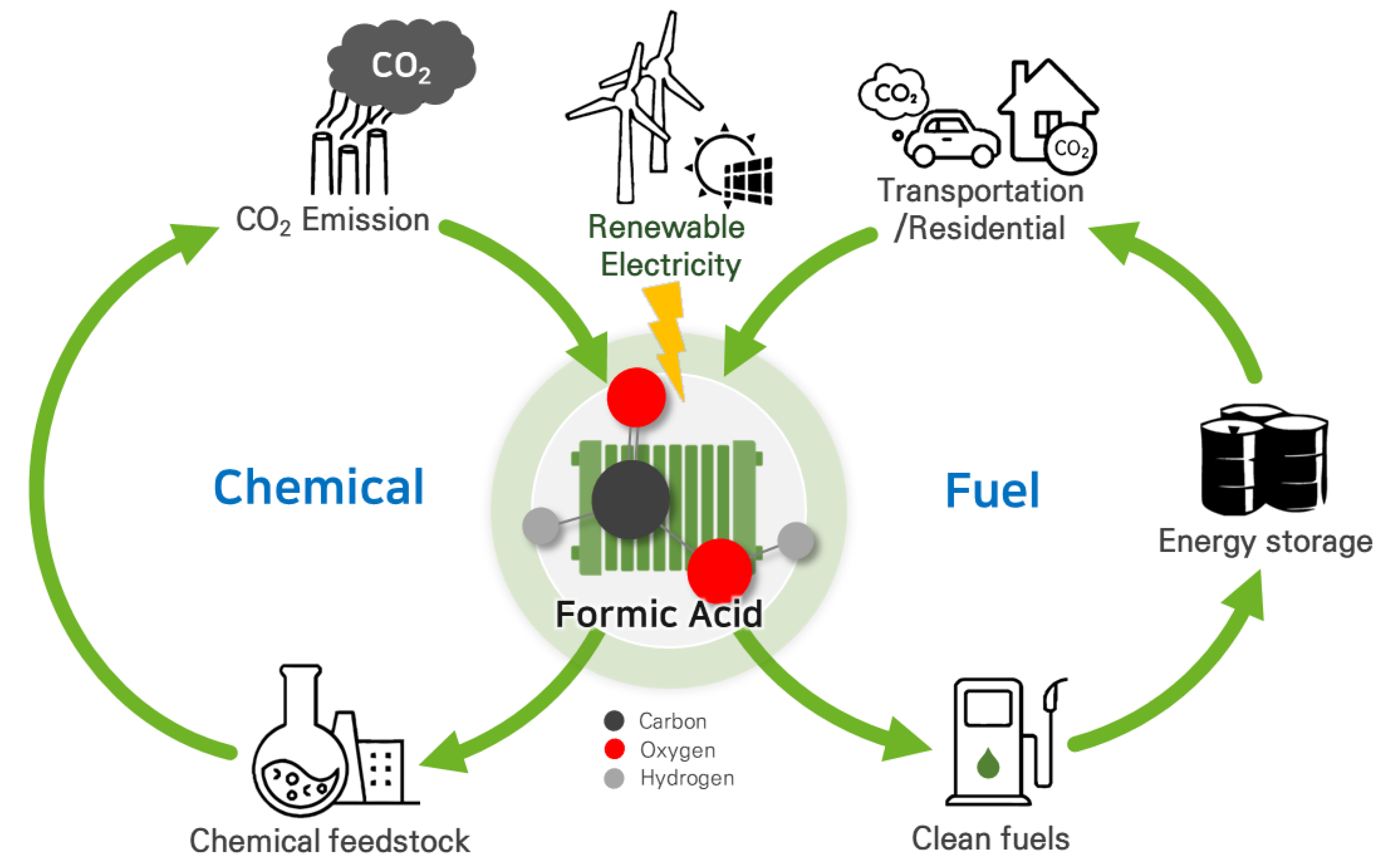
1. Introduction
2. Electrocatalytic CO2 Reduction to Formate
2.1. CO2RR to Formate Using CO2-Dissolved Liquid Feed
2.2. CO2RR to Formate Using Gaseous CO2 Feed
3. Reactor Design for CO2RR to Pure Formic Acid
3.1. Three-Compartment Configurations
3.2. Strategies for High-Purity Formic Acid Recovery
3.3. Opportunities and Challenges
4. Summary and Outlooks
Author Contributions
Funding
Data Availability Statement
Acknowledgments
Conflicts of Interest
References
- Duarah, P.; Haldar, D.; Yadav, V.S.K.; Purkait, M.K. Progress in the electrochemical reduction of CO2 to formic acid: A review on current trends and future prospects. J. Environ. Chem. Eng. 2021, 9, 106394. [Google Scholar] [CrossRef]
- Zarandi, R.F.; Rezaei, B.; Ghaziaskar, H.S.; Ensafi, A.A. Electrochemical reduction of CO2 to ethanol using copper nanofoam electrode and 1-butyl-3-methyl-imidazolium bromide as the homogeneous co-catalyst. J. Environ. Chem. Eng. 2019, 7, 103141. [Google Scholar] [CrossRef]
- Jeon, Y.E.; Ko, Y.N.; Kim, J.; Choi, H.; Lee, W.; Kim, Y.E.; Lee, D.; Kim, H.Y.; Park, K.T. Selective production of ethylene from CO2 over CuAg tandem electrocatalysts. J. Ind. Eng. Chem. 2022, 116, 191–198. [Google Scholar] [CrossRef]
- Salimijazi, F.; Kim, J.; Schmitz, A.M.; Grenville, R.; Bocarsly, A.; Barstow, B. Constraints on the Efficiency of Engineered Electromicrobial Production. Joule 2020, 4, 2101–2130. [Google Scholar] [CrossRef]
- Gunasekar, G.H.; Park, K.; Jung, K.-D.; Yoon, S. Recent developments in the catalytic hydrogenation of CO2 to formic acid/formate using heterogeneous catalysts. Inorg. Chem. Front. 2016, 3, 882–895. [Google Scholar] [CrossRef]
- Ma, Z.; Wan, T.; Zhang, D.; Yuwono, J.A.; Tsounis, C.; Jiang, J.; Chou, Y.-H.; Lu, X.; Kumar, P.V.; Ng, Y.H.; et al. Atomically Dispersed Cu Catalysts on Sulfide-Derived Defective Ag Nanowires for Electrochemical CO2 Reduction. ACS Nano 2023, 17, 2387–2398. [Google Scholar] [CrossRef]
- Jouny, M.; Luc, W.; Jiao, F. General Techno-Economic Analysis of CO2 Electrolysis Systems. Ind. Eng. Chem. Res. 2018, 57, 2165–2177. [Google Scholar] [CrossRef]
- Gu, J.; Hsu, C.-S.; Bai, L.; Chen, H.M.; Hu, X. Atomically dispersed Fe3+ sites catalyze efficient CO2 electroreduction to CO. Science 2019, 364, 1091–1094. [Google Scholar] [CrossRef]
- Zheng, T.; Jiang, K.; Ta, N.; Hu, Y.; Zeng, J.; Liu, J.; Wang, H. Large-Scale and Highly Selective CO2 Electrocatalytic Reduction on Nickel Single-Atom Catalyst. Joule 2019, 3, 265–278. [Google Scholar] [CrossRef]
- Higgins, D.; Hahn, C.; Xiang, C.; Jaramillo, T.F.; Weber, A.Z. Gas-Diffusion Electrodes for Carbon Dioxide Reduction: A New Paradigm. ACS Energy Lett. 2018, 4, 317–324. [Google Scholar] [CrossRef]
- Lee, J.; Lee, W.; Ryu, K.H.; Park, J.; Lee, H.; Lee, J.H.; Park, K.T. Catholyte-free electroreduction of CO2 for sustainable production of CO: Concept, process development, techno-economic analysis, and CO2 reduction assessment. Green Chem. 2021, 23, 2397–2410. [Google Scholar] [CrossRef]
- Lee, S.; Eun Jeon, Y.; Lee, S.; Lee, W.; Kim, S.; Choi, J.; Park, J.; Woo Han, J.; Na Ko, Y.; Eun Kim, Y.; et al. Deciphering Mass Transport Behavior in Membrane Electrode Assembly by Manipulating Porous Structures of Atomically Dispersed Metal-Nx Catalysts for High-Efficiency Electrochemical CO2 Conversion. Chem. Eng. J. 2023, 464, 142593. [Google Scholar] [CrossRef]
- Eppinger, J.; Huang, K.-W. Formic Acid as a Hydrogen Energy Carrier. ACS Energy Lett. 2016, 2, 188–195. [Google Scholar] [CrossRef]
- Wang, L.; Nitopi, S.; Wong, A.B.; Snider, J.L.; Nielander, A.C.; Morales-Guio, C.G.; Orazov, M.; Higgins, D.C.; Hahn, C.; Jaramillo, T.F. Electrochemically converting carbon monoxide to liquid fuels by directing selectivity with electrode surface area. Nat. Catal. 2019, 2, 702–708. [Google Scholar] [CrossRef]
- Mardini, N.; Bicer, Y. Direct synthesis of formic acid as hydrogen carrier from CO2 for cleaner power generation through direct formic acid fuel cell. Int. J. Hydrog. Energy 2021, 46, 13050–13060. [Google Scholar] [CrossRef]
- Moret, S.; Dyson, P.J.; Laurenczy, G. Direct synthesis of formic acid from carbon dioxide by hydrogenation in acidic media. Nat. Commun. 2014, 5, 4017. [Google Scholar] [CrossRef]
- Wang, W.-H.; Himeda, Y.; Muckerman, J.T.; Manbeck, G.F.; Fujita, E. CO2 Hydrogenation to Formate and Methanol as an Alternative to Photo- and Electrochemical CO2 Reduction. Chem. Rev. 2015, 115, 12936–12973. [Google Scholar] [CrossRef]
- Álvarez, A.; Bansode, A.; Urakawa, A.; Bavykina, A.V.; Wezendonk, T.A.; Makkee, M.; Gascon, J.; Kapteijn, F. Challenges in the Greener Production of Formates/Formic Acid, Methanol, and DME by Heterogeneously Catalyzed CO2Hydrogenation Processes. Chem. Rev. 2017, 117, 9804–9838. [Google Scholar] [CrossRef]
- Orella, M.J.; Brown, S.M.; Leonard, M.E.; Román-Leshkov, Y.; Brushett, F.R. A General Technoeconomic Model for Evaluating Emerging Electrolytic Processes. Energy Technol. 2019, 8, 1900994. [Google Scholar] [CrossRef]
- Mellmann, D.; Sponholz, P.; Junge, H.; Beller, M. Formic acid as a hydrogen storage material—Development of homogeneous catalysts for selective hydrogen release. Chem. Soc. Rev. 2016, 45, 3954–3988. [Google Scholar] [CrossRef]
- Liu, L.-X.; Zhou, Y.; Chang, Y.-C.; Zhang, J.-R.; Jiang, L.-P.; Zhu, W.; Lin, Y. Tuning Sn3O4 for CO2 reduction to formate with ultra-high current density. Nano Energy 2020, 77, 105296. [Google Scholar] [CrossRef]
- Kumar, B.; Atla, V.; Brian, J.P.; Kumari, S.; Nguyen, T.Q.; Sunkara, M.; Spurgeon, J.M. Reduced SnO2 Porous Nanowires with a High Density of Grain Boundaries as Catalysts for Efficient Electrochemical CO2-into-COOH Conversion. Angew. Chem. Int. Ed. Engl. 2017, 56, 3645–3649. [Google Scholar] [CrossRef] [PubMed]
- Fan, L.; Xia, C.; Zhu, P.; Lu, Y.; Wang, H. Electrochemical CO(2) reduction to high-concentration pure formic acid solutions in an all-solid-state reactor. Nat. Commun. 2020, 11, 3633. [Google Scholar] [CrossRef]
- Liang, X.-D.; Tian, N.; Hu, S.-N.; Zhou, Z.-Y.; Sun, S.-G. Recent advances of bismuth-based electrocatalysts for CO2 reduction: Strategies, mechanism and applications. Mater. Rep. Energy 2023, 3, 100191. [Google Scholar] [CrossRef]
- Shin, H.; Hansen, K.U.; Jiao, F. Techno-economic assessment of low-temperature carbon dioxide electrolysis. Nat. Sustain. 2021, 4, 911–919. [Google Scholar] [CrossRef]
- Yang, H.; Kaczur, J.J.; Sajjad, S.D.; Masel, R.I. Electrochemical conversion of CO2 to formic acid utilizing Sustainion™ membranes. J. CO2 Util. 2017, 20, 208–217. [Google Scholar] [CrossRef]
- Choi, S.Y.; Jeong, S.K.; Kim, H.J.; Baek, I.-H.; Park, K.T. Electrochemical Reduction of Carbon Dioxide to Formate on Tin–Lead Alloys. ACS Sustain. Chem. Eng. 2016, 4, 1311–1318. [Google Scholar] [CrossRef]
- Kim, Y.E.; Lee, W.; Ko, Y.N.; Park, J.E.; Tan, D.; Hong, J.; Jeon, Y.E.; Oh, J.; Park, K.T. Role of Binder in Cu2O Gas Diffusion Electrodes for CO2 Reduction to C2+ Products. ACS Sustain. Chem. Eng. 2022, 10, 11710–11718. [Google Scholar] [CrossRef]
- Tan, D.; Lee, W.; Kim, Y.E.; Ko, Y.N.; Youn, M.H.; Jeon, Y.E.; Hong, J.; Jeong, S.K.; Park, K.T. SnO2/ZnO Composite Hollow Nanofiber Electrocatalyst for Efficient CO2 Reduction to Formate. ACS Sustain. Chem. Eng. 2020, 8, 10639–10645. [Google Scholar] [CrossRef]
- Tan, D.; Lee, W.; Kim, Y.E.; Ko, Y.N.; Youn, M.H.; Jeon, Y.E.; Hong, J.; Park, J.E.; Seo, J.; Jeong, S.K.; et al. In-Bi Electrocatalyst for the Reduction of CO(2) to Formate in a Wide Potential Window. ACS Appl. Mater. Interfaces 2022, 14, 28890–28899. [Google Scholar] [CrossRef]
- Tan, D.; Lee, W.; Park, K.T.; Jeon, Y.E.; Hong, J.; Ko, Y.N.; Kim, Y.E. Promoting CO2 reduction to formate selectivity on indium-doped tin oxide nanowires. Appl. Surf. Sci. 2023, 613, 155944. [Google Scholar] [CrossRef]
- Hu, H.; Gui, L.; Zhou, W.; Sun, J.; Xu, J.; Wang, Q.; He, B.; Zhao, L. Partially reduced Sn/SnO2 porous hollow fiber: A highly selective, efficient and robust electrocatalyst towards carbon dioxide reduction. Electrochim. Acta 2018, 285, 70–77. [Google Scholar] [CrossRef]
- Lv, W.; Zhou, J.; Bei, J.; Zhang, R.; Wang, L.; Xu, Q.; Wang, W. Electrodeposition of nano-sized bismuth on copper foil as electrocatalyst for reduction of CO2 to formate. Appl. Surf. Sci. 2017, 393, 191–196. [Google Scholar] [CrossRef]
- Wu, Z.; Wu, H.; Cai, W.; Wen, Z.; Jia, B.; Wang, L.; Jin, W.; Ma, T. Engineering Bismuth–Tin Interface in Bimetallic Aerogel with a 3D Porous Structure for Highly Selective Electrocatalytic CO2 Reduction to HCOOH. Angew. Chem. 2021, 133, 12662–12667. [Google Scholar] [CrossRef]
- Bai, X.; Chen, W.; Zhao, C.; Li, S.; Song, Y.; Ge, R.; Wei, W.; Sun, Y. Exclusive Formation of Formic Acid from CO2 Electroreduction by a Tunable Pd-Sn Alloy. Angew. Chem. 2017, 129, 12387–12391. [Google Scholar] [CrossRef]
- Luc, W.; Collins, C.; Wang, S.; Xin, H.; He, K.; Kang, Y.; Jiao, F. Ag–Sn Bimetallic Catalyst with a Core–Shell Structure for CO2 Reduction. J. Am. Chem. Soc. 2017, 139, 1885–1893. [Google Scholar] [CrossRef]
- Zhu, P.; Wang, H. High-purity and high-concentration liquid fuels through CO2 electroreduction. Nat. Catal. 2021, 4, 943–951. [Google Scholar] [CrossRef]
- Xia, C.; Zhu, P.; Jiang, Q.; Pan, Y.; Liang, W.; Stavitski, E.; Alshareef, H.N.; Wang, H. Continuous production of pure liquid fuel solutions via electrocatalytic CO2 reduction using solid-electrolyte devices. Nat. Energy 2019, 4, 776–785. [Google Scholar] [CrossRef]
- Yang, H.; Kaczur, J.J.; Sajjad, S.D.; Masel, R.I. Performance and long-term stability of CO2 conversion to formic acid using a three-compartment electrolyzer design. J. CO2 Util. 2020, 42, 101349. [Google Scholar] [CrossRef]
- Daiyan, R.; Lu, X.; Saputera, W.H.; Ng, Y.H.; Amal, R. Highly Selective Reduction of CO2 to Formate at Low Overpotentials Achieved by a Mesoporous Tin Oxide Electrocatalyst. ACS Sustain. Chem. Eng. 2018, 6, 1670–1679. [Google Scholar] [CrossRef]
- Hori, Y. Electrochemical CO2 Reduction on Metal Electrodes. In Modern Aspects of Electrochemistry; Springer: New York, NY, USA, 2008; pp. 89–189. [Google Scholar] [CrossRef]
- Song, J.; Song, H.; Kim, B.; Oh, J. Towards Higher Rate Electrochemical CO2 Conversion: From Liquid-Phase to Gas-Phase Systems. Catalysts 2019, 9, 224. [Google Scholar] [CrossRef]
- Verma, S.; Lu, X.; Ma, S.; Masel, R.I.; Kenis, P.J.A. The effect of electrolyte composition on the electroreduction of CO2 to CO on Ag based gas diffusion electrodes. Phys. Chem. Chem. Phys. 2016, 18, 7075–7084. [Google Scholar] [CrossRef] [PubMed]
- Kutz, R.B.; Chen, Q.; Yang, H.; Sajjad, S.D.; Liu, Z.; Masel, I.R. Sustainion Imidazolium-Functionalized Polymers for Carbon Dioxide Electrolysis. Energy Technol. 2017, 5, 929–936. [Google Scholar] [CrossRef]
- Dinh, C.-T.; García de Arquer, F.P.; Sinton, D.; Sargent, E.H. High Rate, Selective, and Stable Electroreduction of CO2 to CO in Basic and Neutral Media. ACS Energy Lett. 2018, 3, 2835–2840. [Google Scholar] [CrossRef]
- Fan, T.; Ma, W.; Xie, M.; Liu, H.; Zhang, J.; Yang, S.; Huang, P.; Dong, Y.; Chen, Z.; Yi, X. Achieving high current density for electrocatalytic reduction of CO2 to formate on bismuth-based catalysts. Cell Rep. Phys. Sci. 2021, 2, 100353. [Google Scholar] [CrossRef]
- Grigioni, I.; Sagar, L.K.; Li, Y.C.; Lee, G.; Yan, Y.; Bertens, K.; Miao, R.K.; Wang, X.; Abed, J.; Won, D.H.; et al. CO2 Electroreduction to Formate at a Partial Current Density of 930 mA cm–2 with InP Colloidal Quantum Dot Derived Catalysts. ACS Energy Lett. 2020, 6, 79–84. [Google Scholar] [CrossRef]
- Li, J.; Jiao, J.; Zhang, H.; Zhu, P.; Ma, H.; Chen, C.; Xiao, H.; Lu, Q. Two-Dimensional SnO2 Nanosheets for Efficient Carbon Dioxide Electroreduction to Formate. ACS Sustain. Chem. Eng. 2020, 8, 4975–4982. [Google Scholar] [CrossRef]
- Lu, X.; Leung, D.Y.C.; Wang, H.; Xuan, J. A high performance dual electrolyte microfluidic reactor for the utilization of CO2. Appl. Energy 2017, 194, 549–559. [Google Scholar] [CrossRef]
- Pavesi, D.; van de Poll, R.C.J.; Krasovic, J.L.; Figueiredo, M.; Gruter, G.-J.M.; Koper, M.T.M.; Schouten, K.J.P. Cathodic Disintegration as an Easily Scalable Method for the Production of Sn- and Pb-Based Catalysts for CO2 Reduction. ACS Sustain. Chem. Eng. 2020, 8, 15603–15610. [Google Scholar] [CrossRef]
- Díaz-Sainz, G.; Alvarez-Guerra, M.; Solla-Gullón, J.; García-Cruz, L.; Montiel, V.; Irabien, A. CO2 electroreduction to formate: Continuous single-pass operation in a filter-press reactor at high current densities using Bi gas diffusion electrodes. J. CO2 Util. 2019, 34, 12–19. [Google Scholar] [CrossRef]
- Wang, Z.; Qi, R.; Liu, D.; Zhao, X.; Huang, L.; Chen, S.; Chen, Z.; Li, M.; You, B.; Pang, Y.; et al. Exfoliated Ultrathin ZnIn(2) S(4) Nanosheets with Abundant Zinc Vacancies for Enhanced CO(2) Electroreduction to Formate. ChemSusChem 2021, 14, 852–859. [Google Scholar] [CrossRef]
- Gong, Q.; Ding, P.; Xu, M.; Zhu, X.; Wang, M.; Deng, J.; Ma, Q.; Han, N.; Zhu, Y.; Lu, J.; et al. Structural defects on converted bismuth oxide nanotubes enable highly active electrocatalysis of carbon dioxide reduction. Nat. Commun. 2019, 10, 2807. [Google Scholar] [CrossRef]
- Lee, W.; Kim, Y.E.; Youn, M.H.; Jeong, S.K.; Park, K.T. Catholyte-Free Electrocatalytic CO2 Reduction to Formate. Angew. Chem. Int. Ed. Engl. 2018, 57, 6883–6887. [Google Scholar] [CrossRef]
- Díaz-Sainz, G.; Alvarez-Guerra, M.; Solla-Gullón, J.; García-Cruz, L.; Montiel, V.; Irabien, A. Gas–liquid–solid reaction system for CO2 electroreduction to formate without using supporting electrolyte. AIChE J. 2020, 66, e16299. [Google Scholar] [CrossRef]
- Díaz-Sainz, G.; Alvarez-Guerra, M.; Ávila-Bolívar, B.; Solla-Gullón, J.; Montiel, V.; Irabien, A. Improving trade-offs in the figures of merit of gas-phase single-pass continuous CO2 electrocatalytic reduction to formate. Chem. Eng. J. 2021, 405, 126965. [Google Scholar] [CrossRef]
- Díaz-Sainz, G.; Alvarez-Guerra, M.; Irabien, A. Continuous electroreduction of CO2 towards formate in gas-phase operation at high current densities with an anion exchange membrane. J. CO2 Util. 2022, 56, 101822. [Google Scholar] [CrossRef]
- Bushuyev, O.S.; De Luna, P.; Dinh, C.T.; Tao, L.; Saur, G.; van de Lagemaat, J.; Kelley, S.O.; Sargent, E.H. What Should We Make with CO2 and How Can We Make It? Joule 2018, 2, 825–832. [Google Scholar] [CrossRef]
- Xing, Z.; Hu, L.; Ripatti, D.S.; Hu, X.; Feng, X. Enhancing carbon dioxide gas-diffusion electrolysis by creating a hydrophobic catalyst microenvironment. Nat. Commun. 2021, 12, 136. [Google Scholar] [CrossRef]


| Reactor Type | Cathode | Electrolyte (Catholyte) | Potential (V vs. RHE) | FEformate (%) | jformate (mA cm−2) | Reference |
|---|---|---|---|---|---|---|
| 3-electrode | Sn/SnO2 porous hollow fiber | 0.1 M KHCO3 | −0.95 | 82.1 | 22.9 | [32] |
| Bi on Cu foil | 0.5 M KHCO3 | −0.86 | 91.3 | 3.08 | [33] | |
| Bi-Sn | 0.1 M KHCO3 | −1.0 | 93.9 | 9.3 | [34] | |
| H-type | Sn-Pb alloy | 0.5 M KHCO3 | −1.36 | 79.8 | 45.7 | [27] |
| SnO2/ZnO hollow nanofiber | 0.1 M KHCO3 | −1.34 | 97.9 | 24.9 | [29] | |
| Pd-Sn alloy/C | 0.5 M KHCO3 | −0.43 | 99.6 | ~2 | [35] | |
| Mesoporous SnO2 | 0.1 M KHCO3 | −1.15 | 75 | 10.8 | [40] | |
| In16Bi84 nano-sphere | 0.5 M KHCO3 | −0.94 | 100 | 14.08 | [30] | |
| AgSn/SnOx (core-shell) | 0.5 M KHCO3 | −0.8 | 80 | 16 | [36] | |
| In-doped SnO2 nanowires | 0.5 M KHCO3 | −1.04 | 82 | 6.02 | [31] |
| Reactor Type | Cathode | Membrane | Cathodic Potential/Cell Voltage (V) | FEformate (%) | jformate (mA cm−2) | Concentration of HCOO− (wt%) | Reference |
|---|---|---|---|---|---|---|---|
| GDE-catholyte | Bi2O2CO3 nanosheet | Fumasep FAB-PK-130 | −1.55 (vs. RHE) | 93 | 930 | - | [46] |
| InP colloidal quantum dots | AEM | −2.6 (vs. RHE) | 93 | 930 | - | [47] | |
| SnO2 nanosheet | Selemion | −1.13 (vs. RHE) | 94.2 | 471 | - | [48] | |
| Pb powder | - | 4 | 90 | 352 | - | [49] | |
| Bi nanosheet | Nafion® 117 | −1.18 (vs. RHE)/3.1 | 92.4 | 83.2 | 0.204 | [51] | |
| ZnIn2S4 nanosheet | Nafion® 212 | −1.2 (vs. RHE) | 94 | 245 | - | [52] | |
| Bi nanotube | Selemion | −0.56 (vs. RHE) | 98 | 170 | - | [53] | |
| Sn/C | Nafion® 324 | −2.44 (vs. SHE) | 98 | 200 | - | [50] | |
| Zero-gap | Bi/C | Nafion® 117 | 3.1 | 71.7 | 32.3 | 3.39 | [55] |
| Bi/C | Nafion® 117 | 3.0 | 89.2 | 40.1 | 33.7 | [56] | |
| Sn nanoparticle | Nafion® 115 | 2.2 | 93.3 | 51.7 | 4.15 | [54] | |
| Sn nanoparticle | Nafion® 115 | 2.2 | 77.7 | 29.8 | 11.62 | [54] | |
| Bi/C | SustainionTM | 3.6 | 91.6 | 274.8 | 0.67 | [57] |
| Cathode | Membrane (AEM/CEM) | SSE Material | Feeds | Cell Voltage (V) | FEHCOOH (%) | jHCOOH (mA cm−2) | Concentration of HCOOH (wt%) | Reference | |
|---|---|---|---|---|---|---|---|---|---|
| Cathode/Anode | SSE | ||||||||
| Sn | Sustanion/ Nafion® 324 | Amberlite® IR120 | Humidified-CO2/H2O | H2O | 3.5 | 94 | 131.6 | 9.4 | [26] |
| 2D-Bi | Sustanion/ Nafion® 115 | SVB copolymer | Humidified-CO2/H2O | H2O | 3.08 | 93.1 | 32.1 | 0.51 | [38] |
| Humidified-CO2/H2O | Humidified-N2 | 2.75 | 40 | 80 | 49.3 | ||||
| Humidified-CO2/ Humidified-H2 | Humidified-N2 | 1.33 | 73.3 | 163 | - | ||||
| Bi | PSMIM/ Nafion® 115 | SVB copolymer | Humidified-CO2/ Humidified-H2 | H2O | 2.19 | 97 | 450 | ~3 | [23] |
| Humidified-N2 | 1.49 | 40 | 80 | 11 | |||||
| Dry N2 | - | ~22 | 44 | ~100 | |||||
| Bi2O3 | Sustanion/ Nafion® 324 | Amberlite® IR120 | Humidified-CO2/H2O | H2O | 3.76 | 91.3 | 182.6 | 6.03 | [39] |
| Cathode configurations | Cathode | POCO Graphite block with the serpentine flow path |
| GDE cathode | Toray paper, 50% PTFE proofing | |
| GDE catalyst | Sn nanoparticles (99.9%, 60–80 nm, US Research Nanomaterials, Inc.), catalyst layer air atomized onto GDE cathode with varying amounts of PTFE suspension and 5% imidazolium-based ionomer, and 5% carbon nanotubes. | |
| CO2 flowrate | 20 mL/min, not humidified for ambient temperature operation | |
| Anode configurations | Anode 1 | POCO Graphite block with the serpentine flow path. The anode was a GDE electrode with a 2 mg cm−2 IrO2 catalyst (99.99%, Alfa Aesar) onto 5% PTFE proofing Toray paper |
| Anode 2 | Titanium Grade 2 anode block with the serpentine flow path. The Anode screen having IrO2-based metal oxide coating on expanded titanium (Water Star) was spot welded onto the titanium anode block | |
| Anolyte recirculation rate | DI water, 8–12 mL/min | |
| Center flow compartment | Ion exchange media | Amberlite® IR120 strong acid ion exchange resin fill, 620–830 μm beads, and other selected ion exchange resins |
| Center compartment | 1 mm thickness, 2.25 cm × 2.25 cm, 0.50 mL (empty), estimated 40% void volume, i.e., 0.2 mL free volume with ion exchange resin | |
| Center compartment frame | Polycarbonate, the machined flow path for solution flow in/out | |
| DI water feed | Selected rate of 0.03 1 mL/min into center flow compartment | |
| Anion membrane | Dioxide Materials Sustainion™ X37 imidazolium-based anion exchange membrane:60–80 μm thickness (wet), ion exchange capacity of 1.05 mEq/g (950 EW), membrane conductivity in water, through the plane, of about 60–70 mS cm−1 | |
| Cation membranes | DuPont Nafion® Membranes Tested: 212, 115, 324 | |
| Active geometric area | 5 cm2 | |
| Cell operating temperature | Ambient, 20–25 °C |
Disclaimer/Publisher’s Note: The statements, opinions and data contained in all publications are solely those of the individual author(s) and contributor(s) and not of MDPI and/or the editor(s). MDPI and/or the editor(s) disclaim responsibility for any injury to people or property resulting from any ideas, methods, instructions or products referred to in the content. |
© 2023 by the authors. Licensee MDPI, Basel, Switzerland. This article is an open access article distributed under the terms and conditions of the Creative Commons Attribution (CC BY) license (https://creativecommons.org/licenses/by/4.0/).
Share and Cite
Kang, Y.; Kim, T.; Jung, K.Y.; Park, K.T. Recent Progress in Electrocatalytic CO2 Reduction to Pure Formic Acid Using a Solid-State Electrolyte Device. Catalysts 2023, 13, 955. https://doi.org/10.3390/catal13060955
Kang Y, Kim T, Jung KY, Park KT. Recent Progress in Electrocatalytic CO2 Reduction to Pure Formic Acid Using a Solid-State Electrolyte Device. Catalysts. 2023; 13(6):955. https://doi.org/10.3390/catal13060955
Chicago/Turabian StyleKang, Yeomin, Taekyung Kim, Koo Young Jung, and Ki Tae Park. 2023. "Recent Progress in Electrocatalytic CO2 Reduction to Pure Formic Acid Using a Solid-State Electrolyte Device" Catalysts 13, no. 6: 955. https://doi.org/10.3390/catal13060955
APA StyleKang, Y., Kim, T., Jung, K. Y., & Park, K. T. (2023). Recent Progress in Electrocatalytic CO2 Reduction to Pure Formic Acid Using a Solid-State Electrolyte Device. Catalysts, 13(6), 955. https://doi.org/10.3390/catal13060955