Abstract
Currently, the catalytic reduction of nitrobenzene requires more efficient and low-cost catalysts. In this work, a new copper-based metal-organic framework (MOF) was designed by the calcination of Cu–MOF at 700 °C (denoted as Cu@C). The catalyst showed superior catalytic performance toward the reduction of nitrobenzene, using sodium borohydride (NaBH4) as the reducing agent, and the catalyst exhibited high nitrobenzene conversion (100%) and a quick reaction time (8 min). This was one of the highest efficiencies among non-noble metal catalysts reported so far, as general non-noble metal catalysts typically require more than 15 min. This catalyst had excellent acid resistance after etching using sulfuric acid (H2SO4) for 24 h with a nitrobenzene conversion rate that was still more than 90%. In addition, it could be used more than five times and the catalytic properties remained essentially unchanged, without any reactivation treatment. Therefore, this study could offer a new efficient non-noble metal catalyst for the reduction of nitro compounds.
1. Introduction
Over the past several decades, environmental pollution including water pollution, air pollution, and noise pollution has become increasingly serious [1]. These resulting problems are endangering all lives worldwide. Among these issues, the treatment of water pollution is closely related to human water use, and it is important that scientists worldwide urgently solve this problem. As a typical water pollutant, nitrobenzene is an indispensable basic raw material for medicine, dyes, pesticides, and other industries [2,3,4] which produce a considerable amount of nitrobenzene wastewater in their production processes. The structure of nitrobenzene is characterized by a nitro group on the benzene ring, and this nitro group, with a strong electron absorption ability, will lead to a decrease in the electron cloud density of the benzene ring [5]. The strong blunting effect will also cause the low chemical activity of nitrobenzene, making it difficult to biodegrade and causing it to easily accumulate in the environment [6,7]. Meanwhile, nitrobenzene has high toxicity, carcinogenesis, teratogenicity, and mutagenicity [8,9]. At present, the main method of purifying nitrobenzene wastewater is reducing nitrobenzene to aniline. Aniline is one of the most important amines, and is widely used in the manufacture of dyes, drugs, resins, and other aspects. Compared with nitrobenzene, wastewater reduced to aniline will greatly reduce its toxicity to microorganisms and more easily be mineralized by aerobic microorganisms [8]. Moreover, opposite to the electron-absorbing effect of the nitro group, the existence of amidogen obviously improves the biodegradability of wastewater and aniline is also more prone to aerobic microbial mineralization [9]. Thus, reducing nitrobenzene to aniline is the key to treating nitrobenzene wastewater.
Pd, Pt, and other noble metal catalysts have shown very high catalytic activity in nitrobenzene reduction in recent decades [10]. Neeli Chinna Krishna Prasad et al. [11] synthesized a Pd/NH2-UiO-66 catalyst using the anion exchange method, and the reduction of nitrobenzene was carried out with formic acid as the reducing agent under mild conditions. The yield of aniline was 98%. Junrui Li et al. [12] prepared a Pt/CMK-3 catalyst and obtained ordered mesoporous materials (OMCS) using a common impregnation method. The conversion rate of nitrobenzene was 98%, and it could be used continuously more than 14 times. Although these catalysts showed high catalytic activity, their applications were limited due to the high cost and few available sources of noble metals. However, significantly less work has been conducted on non-noble metals due to their low reactivity. Jiang et al. [13] obtained a Ni/bentonite catalyst through the wet impregnation method and catalyzed nitrobenzene to aniline on a fixed-bed reaction device, where the yield of aniline reached 94%. Nevertheless, it was hard to control the grain sizes and difficult to recycle after the reaction. Thus, further improvements are still needed. Therefore, it is necessary to develop an efficient, economical, and easy-to-recycle non-noble metal catalyst [14].
Metal-organic frameworks (MOFs) are new porous materials [15] that have attracted extensive attention due to their structural diversity, good crystallinity, stability, high specific surface area, and large porosity [16,17,18]. Among them, MOFs also have a good application prospect in the catalytic field. For example, MOFs with unsaturated coordination metal centers can catalyze a number of Lewis acid-catalyzed reactions by removing the small ligand molecules to expose the Lewis acid sites [19,20]. In addition, MOFs can be transformed to carbon materials with high specific surfaces and large pore sizes after calcination at high temperatures [21,22]. The high specific surface area and large pore size of the calcinates are conducive to capturing other substances and transmitting them into the skeleton, allowing the generated metal nanoparticles to fully contact the captured substances [23,24]. However, the formation of a carbon skeleton structure after calcination can fully cover the generated metal nanoparticles and prevent their agglomeration as a result of high activity. Yusran et al. [25] used ZIF-67 as the precursor to synthesize a Co@N-C nanocatalyst which showed high catalytic performance in the reduction of 4-nitrophenol, because the Co nanoparticles were fully coated by the carbon sheet and no agglomeration occurred. This protective effect is also the reason why MOF derivatives have shown good recyclability and difficulty causing secondary pollution, which is in line with green chemistry [26]. Therefore, MOF materials and their derivatives have shown excellent catalytic performance and very broad application prospects in the field of basic catalysis.
In this work, a new Cu–MOF was synthesized using a solvothermal method. Additionally, then the Cu–MOF was calcinated under nitrogen flow to obtain the product of Cu@C. The reason we chose Cu as the active center was that Cu can strongly absorb hydrogen atoms and other molecules, increasing the lifetime of the reactive species and the possibility of reaction. The materials were characterized using X-ray diffraction (XRD), Fourier transform infrared (FT-IR) spectroscopy, scanning electron microscopy (SEM), transmission electron microscopy (TEM), thermogravimetric analysis (TGA), and X-ray photoelectron spectroscopy (XPS). As expected, the catalysts used for the reduction of nitrobenzene to aniline showed high performance compared with previously reported materials.
2. Results and Discussion
2.1. Materials Synthesis and Characterizations
The hydrothermal reaction of copper ions (Cu2+) with BDC, EtOH, and H2O in DMF formed a bright blue precipitate. Then, we used XRD to verify the crystallinity of the bright blue precipitate. Based on the sharp diffraction peak in the XRD pattern (Figure 1a) of Cu–MOF, we found that the material had high crystallinity. As a precursor, Cu–MOF was then carbonized at 500 °C, 600 °C, 700 °C, and 800 °C and the XRD patterns showed the characteristic peaks of two phases, namely Cu0 (JCPDS Card No. 04-0836) [27] and Cu2O (JCPDS Card No. 05-0667) [28,29] (Figure 1b). However, the phase of Cu2O was not obvious and according to the results of XRD patterns, we inferred that the main form of Cu in the carbonized Cu–MOF was Cu0. Unfortunately, no single crystal could grow from the synthesized Cu–MOF after all attempted measures in this work, and the accurate data and structure of the single crystal could not be obtained.
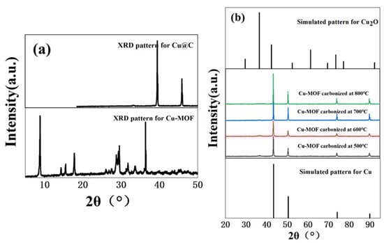
Figure 1.
(a) XRD patterns of Cu–MOF before and after carbonization (700 °C), and (b) XRD patterns of Cu@C at different carbonization temperatures (500–800 °C).
The surface area and pore size were analyzed using the N2 adsorption/desorption isotherms (Figure 2 and Figure S1). The images showed that the adsorption behaviors of Cu–MOF and Cu@C conformed to type II N2 adsorption isotherms with type H3 hysteresis loops, as classified by IUPAC [30]. This indicated that the materials were not porous, but rather mesoporous materials consisting of slits resulting from the aggregates of the layered structures. The BET surface area, average pore diameter, and total pore volume are listed in Table 1. After the carbonization of Cu–MOF, the BET surface area and pore volume increased, while the pore size decreased. As the initial skeleton was carbonized, a portion of the structure collapsed, resulting in the formation of the Cu@C catalyst structure, which released more surface and the formation of Cu nanoparticles. Therefore, the surface area and pore volume increased. Additionally, the decrease in pore size indicated that the amount of pores increased after calcination.
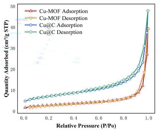
Figure 2.
N2 adsorption isotherms of Cu–MOF, Cu@C at 77 K.

Table 1.
Surface area analysis of Cu–MOF and Cu@C.
Thermogravimetric analysis of the as-made Cu–MOF material was conducted (Figure 3 and Figure S2). According to the TGA plot of Cu–MOF, two major weight-loss steps were observed. The first major weight-loss step occurred at 260 °C and reached an inflection point at 348 °C, and a total of 10.50% of the mass was lost in this process. This mass loss was possibly due to the decomposition of DMF, EtOH, and H2O covalently bound to Cu(II). Another major weight loss value of 26.31% was observed after a brief heat-up reached approximately 354 °C. This indicated that the departure of the ligand molecules led to the collapse and disassembly of the MOF backbone after 354 °C, and this process continued until 450 °C. A subsequent mass loss of 5.16% up to 800 °C was due to the departure of the remaining ligand molecules and the continuing collapse of the framework. This also indicated that the residual mass of the final metallic copper (Cu0) and Cu2O products in carbon sheets was 57.61%.
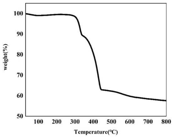
Figure 3.
TGA plot of the as-synthesized Cu–MOF.
SEM and TEM were used to reveal the morphology and particle size of Cu–MOF and Cu@C. SEM analysis showed that Cu–MOF had a relatively smooth surface and a needle-rod morphology (Figure 4a), while Cu@C obtained after calcination had a dendritic filamentous shape (Figure 4b). The clumped structure around the filaments also indicated the collapse of the Cu–MOF structure after calcination. The corresponding elemental mapping images for C, N, O, and Cu (Figure S3) revealed the uniform distribution of these elements throughout Cu–MOF. As indicated by TEM analysis (Figure 4c), the particle sizes of the Cu and Cu2O nanoparticles (dark parts) were mainly concentrated within 20–50 nm with very few large-sized nanoparticles, and the particles were fully encapsulated inside the carbon sheets (gray parts). This also proved that the preparation method of Cu@C in this paper could effectively reduce the nanoparticles’ agglomeration. In addition, mesoporous structures with a size of 30–50 nm and few macropore structures were found according to the carbon sheets of TEM.
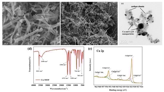
Figure 4.
(a) SEM image of Cu–MOF, (b) SEM image of Cu@C (700 °C) and (c) TEM image of Cu@C (700 °C), (d) FT-IR of Cu–MOF, and (e) XPS of Cu@C.
The coordination bonds among H2BDC, EtOH, H2O, and Cu2+ were characterized via the FI-IR spectra (Figure 4d). The sharp peak observed at 3611 cm−1 was attributed to the stretching frequency of the O–H bond, and the broad peak observed at 3440 cm−1 corresponded to the O–H peak of hydrogen bond association formed by EtOH and H2O. Then, two sharp peaks at 1572 cm−1 and 1390 cm−1 were attributed to the COO asymmetric and symmetric stretching modes of the coordinated carboxylic acid groups, respectively. Meanwhile, no peaks appeared in the range of 1710–1760 cm−1, where the carbonyl peaks were related to the protonated carboxyl group, indicating the successful coordination between Cu2+ and the carboxyl group of H2BDC [31,32]. The two bands at 1500 cm−1 and 736 cm−1 belonged to the vibrations of the phenyl ring, while the band at 563 cm−1 corresponded to the Cu–O bond [31].
In the XPS Cu 2p spectrum (Figure 4e), the two peaks with binding energies of 923.50 eV and 952.30 eV were ascribed to Cu 2p3/2 and Cu 2p1/2, respectively. For Cu 2p3/2, the peak at 932.48 eV with a 1.03 FWHM was attributed to Cu(I), while the signal of the Cu(II) peak contribution was observed at about 934.41 eV with a 2.66 FWHM. For Cu 2p1/2, the peak at 952.24 eV with a 1.34 FWHM was attributed to Cu(I), while the other Cu(II) peak was observed at about 953.42 eV with a 3.28 FWHM. Moreover, the satellite peaks at 941.34 eV and 943.89 eV in Cu 2p3/2 combined with the peak at 962.30 eV in Cu 2p1/2 were also related to Cu(II). According to the Cu 2p spectrum, we also confirmed that the copper element was mainly in the form of Cu2O, with a very small amount of CuO. Additionally, the ratio of atomic% of Cu+ and Cu2+ was nearly 5.5:1 (see details in Table S1). This meant that no peaks of metallic copper (Cu0) were observed in the XPS spectrum. However, the XRD patterns (Figure 1b) matched with metallic copper (Cu0) for a part of Cu2O. The reason for the inconsistency with the XRD patterns was mainly due to the limited detection depth of XPS [33]. Because the calcination of Cu–MOF was carried out in an inert atmosphere (N2 atmosphere), carbon particles were generated during the decomposition process of Cu–MOF. The presence of carbon would reduce Cu(II) to Cu0 (when carbon was sufficient) and Cu2O (when carbon was deficient) at high temperatures. The flow of nitrogen throughout the process possibly blew away the carbon particles generated on the sample surface, causing carbon deficiency; therefore, the generated Cu2O was mainly distributed on the surface of Cu@C. This difference in stratification caused the inconsistencies between the XPS and XRD patterns. The small amount of CuO came from unreduced Cu(II) and the slow oxidation of Cu2O from the oxygen in the air.
2.2. Catalytic Reduction of Nitrobenzene
Currently, one of the most commonly used methods to reduce nitro compounds involves using sodium borohydride (NaBH4) as the reducing agent [34]. However, due to the low chemical activity of nitrobenzene, reducing nitrobenzene directly with NaBH4 is difficult, and, as a result, this reaction must be assisted by an appropriate catalyst. Therefore, to evaluate the catalytic activity of the prepared Cu–MOF and Cu@C, these materials were tested by the reduction reaction with nitrobenzene as the reactant and NaBH4 as the reducing agent, and ethanol was chosen as the solvent in the reaction system. This process was monitored using UV–vis absorption spectroscopy. Visually, when the catalyst was added to the reaction solution, many bubbles were immediately produced. As the reaction continued, the solution with Cu@C changed from colorless to a pale-yellow color to colorless again; however, the solution with Cu–MOF became cloudy. According to the UV–vis spectrum of the solution with Cu@C, the absorption peak of nitrobenzene (260 nm) decreased continuously, while the peak of aniline (281 nm) increased (Figure 5). However, because the characteristic peak of nitrobenzene completely covered the peak of aniline, this change was reflected by the change in the peak curve near 235 nm, and the reduction reaction was completed in only 8 min (Figure 5b). In the other Cu–MOF group, the curve changes were interesting (Figure 5a). During the first 20 min, the concentration of nitrobenzene barely changed; however, after 20 min, its concentration decreased rapidly. Due to the quantity of bubbles produced after adding Cu–MOF, we performed a control test, which consisted of adding Cu–MOF under the same conditions but without the addition of nitrobenzene. We observed that many bubbles were still produced and the solution became cloudy. Soon, some black solids appeared on the bottom of the tube. Therefore, we concluded that the uncalcined Cu–MOF could be reduced by NaBH4, and it showed no obvious catalytic activity for the reduction of nitrobenzene. Only when the Cu–MOF was transformed to the black solids by NaBH4 did the exposed metal active center show high catalytic activity for the reaction. We then conducted two additional check tests, which confirmed the high catalytic performance of Cu@C. As previously stated, it was difficult for NaBH4 to reduce nitrobenzene without a catalyst, and this was confirmed by the test where we added only NaBH4 to the solution; the concentration of nitrobenzene was almost unchanged (Figure 6a). In addition, Cu@C without NaBH4 was studied (Figure 6a). The concentration of nitrobenzene decreased with time, but its concentration increased slightly at 20 min. This was due to the adsorption of Cu@C on nitrobenzene, indicating that adsorption equilibrium was reached after 20 min.
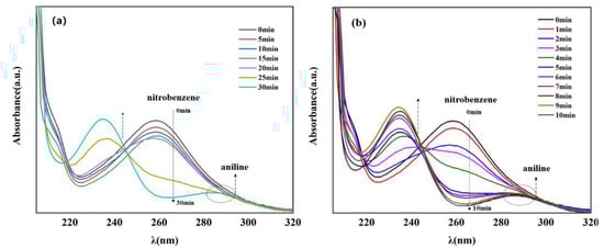
Figure 5.
UV–vis spectra of nitrobenzene reduction with (a) Cu–MOF (5.0 mg) and (b) Cu@C (10.0 mg), both under the following conditions: 0.2 mmol nitrobenzene, 5.0 mmol NaBH4, and 10.0 mL of EtOH at room temperature. Note that the characteristic peak of nitrobenzene was observed at 260 nm and that of aniline was observed at 281 nm.
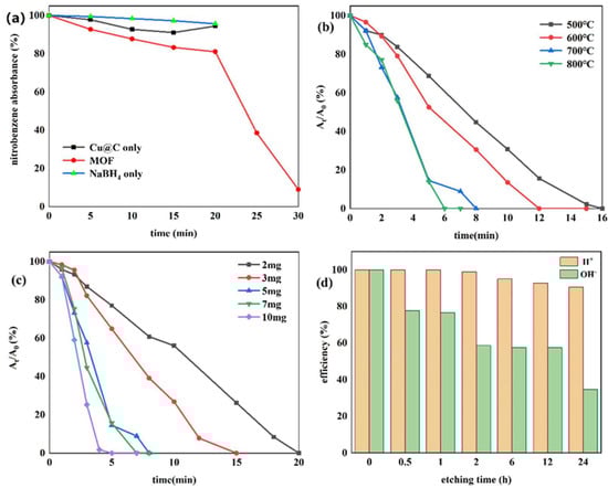
Figure 6.
(a) Reduction of nitrobenzene with Cu–MOF instead of Cu@C, Cu@C without NaBH4, and NaBH4 without Cu@C; the effects of (b) carbonization temperature, (c) the amount of Cu@C, and (d) the etching times of H2SO4 and NaOH.
Research concerning the hydrogenation of nitrobenzene using different catalysts and reducing agents is summarized in Table 2. We observed that using Cu@C as the catalyst in this work only required 8 min to catalyze nitrobenzene, although it was not faster than some noble metal catalysts, such as Au/Ag-TPDT NR and [PdCl2(L4)2]@MWCNTs. However, it showed higher or comparable catalytic efficiency than some non-noble metal catalysts. Therefore, Cu@C can be used as a potential non-noble metal catalyst for the reduction of nitrobenzene.
Table 2.
Comparison between the different materials that may be used for the reduction of nitrobenzene using NaBH4.
The kinetic equation for Cu@C was plotted, as shown in Figure S4, and can be written by
where Ct and At are the concentration and absorbance of nitrobenzene at time t, respectively, and k is the apparent rate constant. The concentration of NaBH4 in the reaction was sufficient to be considered constant throughout the reduction reaction. Thus, the reaction process could be described as a pseudo-first-order kinetic equation from which the concentration of nitrobenzene and the rate constant (k) could be calculated. Additionally, the value of k of Cu@C in this equation was 7.22 × 10⁻³ s−1 (Figure S4).
ln(Ct/C0) = ln(At/A0) = −kt
The effect of the carbonization temperature (500–800 °C) of Cu@C was studied (Figure 6b and Figure S5). With an increase in carbonization temperature, the time required to reduce nitrobenzene decreased, and only 6 min were required to complete the reaction when the carbonization temperature reached 800 °C. This was because higher temperatures caused a more severe collapse of the carbon sheets, leaving the active metal center more exposed. The XRD patterns also confirmed that with an increase in temperature, the peaks of Cu@C became sharper with increasing intensity, with the characteristic peaks of Cu2O fading away (Figure 1b). The relationship between Cu@C quantity and catalytic efficiency was also studied (Figure 6c and Figure S6), and the results were predictable, showing that more Cu@C led to a decrease in the reaction time, as more Cu@C meant more catalytic active sites.
Subsequently, acid and base etching experiments, which could possibly destroy the surface of the catalysts, were carried out to confirm the influence of acidic or basic environments on the catalytic performance of Cu@C (Figure 6d and Figure S7). This influence was determined by immersing Cu@C in 0.5 mol/L H2SO4 or NaOH aqueous solutions for several hours. The etching of H2SO4 led to a slight decrease in the catalytic performance of Cu@C, but this effect was not serious. However, the etching of NaOH potentially led to a more severe decline in catalytic efficiency. Although the destruction of the catalyst by NaOH was potentially phased (catalytic efficiencies of 2, 6, and 12 h were almost the same), 30 min of etching time resulted in a 20% loss of catalytic ability and 24 h of etching time resulted in a loss of nearly 70%. This was possibly because under high alkalinity, OH− would assist (OH− itself or dissolved oxygen in the solution) in oxidizing Cu and Cu2O, resulting in catalyst deactivation [43]. Therefore, these results indicated that the catalyst had good acid resistance but poor alkali resistance.
The recyclability of Cu@C was also studied (Figure 7a), with a total number of five experimental cycles. According to the experimental results, catalytic performance did not decrease after five cycles without any reactivation or catalytic post-treatment. Moreover, after each cycle, the end of the reaction (end of bubble production) was slightly faster than in the previous cycle. This meant that the catalyst became more active after each cycle. We speculated that the catalyst further exposed the originally unexposed catalytic active sites after the reaction, further improving catalytic efficiency [44]. The XRD pattern of Cu@C after cycling was investigated (Figure 7b), and the pattern showed that after five cycles, there were no obvious changes in Cu@C. The peak related to Cu2O was enhanced, possibly because after the reaction, the distribution of Cu and Cu2O became more uniform as opposed to a layered distribution. Moreover, the XRD pattern further confirmed that Cu@C had excellent recyclability.
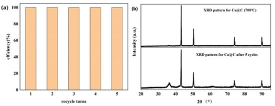
Figure 7.
(a) Recyclability of Cu@C and (b) the XRD patterns for Cu@C before and after five cycles.
2.3. Catalytic Mechanism
Using Cu@C as the catalyst and NaBH4 as the reducing agent, this catalytic reaction could be attributed to the mechanism proposed by Mahata et al. [45], who proposed parallel adsorption of nitrobenzene on the catalyst followed by the direct reduction to aniline via nitrobenzene and phenylhydroxy amine, which was possibly the most advantageous route for the catalytic efficiency of the prepared materials. Herein, we propose a possible mechanism for the complete reduction of nitrobenzene to aniline on the Cu@C surface (Figure 8). First, BH4− ions were adsorbed on Cu0, forming H-Cu0 (Figure 8a). Then, the π-electron cloud of the benzene ring interacted with the Cu@C surface (the adsorption of nitrobenzene). Due to the high electron migration efficiency of Cu0, H-Cu0 could easily migrate electrons to the nitrogen atoms, and the released H+ combined with the oxygens of the nitro group, removing water molecules and forming hydroxylamine, which was further dehydrated and finally reduced to amino groups. Furthermore, according to previous experimental results, the small amount of Cu2O mainly concentrated on the Cu@C surface. The presence of Cu2O accelerated the reduction reaction because Cu2O could accept electrons from BH4−, reducing Cu(I) to in situ Cu0 (Figure 8b). This process of in situ Cu0 formation would catalyze the reduction of nitrobenzene through the adsorption of nitrobenzene and BH4− and hydride transfer. Then, after electron migration and the desorption of aniline, Cu0 was oxidized to Cu(I) again [43]. This process helped accelerate the catalytic reaction. This may also be one of the reasons for the excellent performance of the Cu@C catalyst.
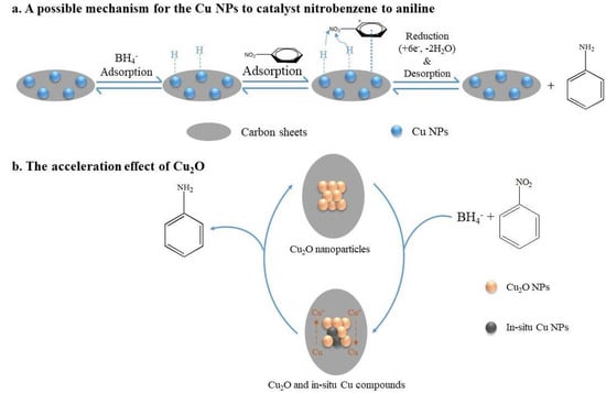
Figure 8.
The mechanism for the reduction of nitrobenzene to aniline.
3. Materials and Methods
1,4-benzenedicarboxylic acid (H2BDC), cupric nitrate trihydrate (Cu(NO3)2·3H2O), and nitrobenzene were supplied from Titan Scientific Co., Ltd. (Shanghai, China). N, N-dimethylformamide (DMF), and ethanol absolute (EtOH) were supplied from ZhiYuan Reagent Co., Ltd. (Tianjin, China). Sodium borohydride (NaBH4) was supplied from the Industrial Development Zone, Mulan Town, Xindu (Chengdu, China). All chemicals and organic solvents were introduced without further purification. The aqueous solutions were prepared using deionized water.
3.1. Synthesis of Cu–MOF and Cu@C
Cu–MOF was synthesized using the hydrothermal method. First, Cu(NO3)2·3H2O (5.0 mmol, 1.2 g) and terephthalic acid (H2BDC, 4.0 mmol, 0.6 g) were dissolved in a 30.6 mL mixture consisting of DMF, ethanol, and deionized water (1:1:1, 10.2 mL each). Then, the mixture was placed on a magnetic stirrer and stirred at room temperature for 1 h. After stirring, the mixture was transferred to the reaction kettle and then placed in the oven at 110 °C for 24 h, finally yielding a bright blue powder consisting of Cu–MOF. The precipitate was alternately washed with DMF and ethyl alcohol three times before drying at 90 °C in the oven.
Cu@C was synthesized via the carbonization of Cu–MOF at 500 °C, 600 °C, 700 °C, and 800 °C for 6 h under nitrogen gas flow at a heating rate of 5 °C/min.
3.2. Characterization Techniques
The powder XRD patterns of all materials were recorded on a X-ray diffractometer (Rigaku TTR-III, Tokyo, Japan) with Cu Kα radiation at 3.0 kV. SEM images were obtained using scanning electron microscopy-SEM (TESCAN MIRA LMS, Brno, Czech Republic) with an accelerating voltage of 3.0 kV, and mapping images were obtained with an accelerating voltage of 15.0 kV. TEM images were recorded using transmission electron microscopy-TEM (FEI Tecnai, Hillsboro, OR, USA) with an accelerating voltage of 80.0 kV. TGA was performed with a thermal analyzer (Netzsch TG 209 F1, Bavaria, Germany) under nitrogen gas flow from 30 °C to 750 °C with a heating rate of 5 °C /min. XPS measurements were performed with a X-ray photoelectron spectrometer (Thermo K-Alpha+, Waltham, MA, USA) using an Al Kα ray light source to measure the total ambient gas pressure (~2.0 × 10⁻⁵ Pa). The FT-IR spectra spectrum (Thermo Scientific Nicolet iN10, Waltham, MA, USA) was recorded in the wavenumber range of 4000–400 cm−1 using the KBr disc technique. The N2 adsorption–desorption isotherms and pore size distributions were obtained using a 4-station automatic specific surface analyzer (Micromeritics APSP 2460, Norcross, GA, USA). The samples were degassed at 120 °C for 6 h under a vacuum before testing, and the specific surface area and pore volume were calculated using the Brunauer–Emmett–Teller (BET) and Barrett–Joyner–Halenda (BJH) methods, respectively.
3.3. Catalytic Reduction of Nitrobenzene
The catalytic reduction experiment of nitrobenzene was carried out under the conditions of Cu–MOF or Cu@C as the catalysts, NaBH4 as the reducing agent, and EtOH as the solvent. The specific process involved evenly mixing nitrobenzene (0.2 mmol) with EtOH (10.0 mL) and then successively adding NaBH4 (19.0 mg, 5.0 mmol) and Cu–MOF (10.0 mg) or Cu@C (2.0 mg, 3.0 mg, 5.0 mg, 7.0 mg, and 10.0 mg, 700 °C) or Cu@C (5.0 mg, 500 °C, 600 °C, and 800 °C) to the mixture, individually. The reaction solution was stirred for 1 h at room temperature. The entire reaction process was detected by a UV–vis spectrophotometer. At certain times, 60.0 μL was obtained and diluted into 5.0 mL of EtOH before detection.
3.4. Stability and Recyclability of the Catalyst
The catalyst stability test was divided into two parts consisting of the acid resistance test and alkaline resistance test, which meant etching the catalyst in an acidic solution (0.5 mol/L H2SO4 aqueous) and an alkaline solution (0.5 mol/L NaOH aqueous) for several hours (0.5 h to 24 h, respectively), respectively. The amount of Cu@C was 5 mg. After etching for every certain time, we separated the catalyst from the solution. Then, the catalyst was rinsed with EtOH several times to remove the remaining etching solution. After that, the catalyst was separated via centrifugation and placed in the solution under the following conditions: 0.2 mmol nitrobenzene, 5.0 mmol NaBH4, and 10.0 mL of EtOH at room temperature. When the reaction time reached 8 min, the reaction solution was taken out and tested using a UV–vis spectrophotometer.
The recyclability of the catalyst was evaluated using 10.0 mg of Cu@C, which was placed in the same conditions of the stability test. After every cycle, the catalyst was separated via centrifugation. Then, the reacted liquid was removed and replenished with a new solvent under the same conditions. When the reaction time reached 5 min, the reaction solution was taken out and tested using the UV–vis spectrophotometer.
4. Conclusions
In summary, we successfully synthesized Cu–MOF using the hydrothermal method. The precursor Cu–MOF was used to produce Cu@C through calcination without the need for additional carbon sources. Moreover, inside the calcined catalyst, Cu@C was fully and uniformly coated on the carbon sheets, with no obvious agglomeration. Both Cu–MOF and Cu@C showed obvious catalytic effects on nitrobenzene; however, Cu–MOF reacted with NaBH4 first and then catalyzed the reaction, which caused the additional consumption of the reducing agent and easily produced secondary pollution. However, Cu@C had no such problem and it could provide an efficient and fast catalytic environment without additional pollution. The presence of carbon could also significantly protect the catalytic active sites and reduce damage caused by the catalytic processes. Therefore, it could be reused many times without a significant decrease in catalytic activity. In addition, Cu@C showed good acid resistance and still showed excellent catalytic activity after 24 h of H2SO4 etching; however, its alkaline resistance was weak, and its performance decreased significantly after etching with NaOH. Therefore, this catalyst was found to be suitable for use in acidic and weakly alkaline environments. In conclusion, Cu@C could be used as a potential catalyst for the reduction of nitro compounds.
Supplementary Materials
The following supporting information can be downloaded at: https://www.mdpi.com/article/10.3390/catal13060956/s1, Figure S1: Pore size of Cu–MOF and Cu@C; Figure S2: Specific TG and DTG plots of the as-synthesized Cu–MOF; Figure S3: SEM image of Cu–MOF and corresponding elemental mapping images for Cu, C, N and O; Figure S4: Linear relationship of ln(At/A0) vs. time using Cu@C (5.0 mg), room temperature; Figure S5: The effect of the temperature of carbonization of Cu@C of (a) 500 °C, (b) 600 °C, (c) 700 °C, and (d) 800 °C; Figure S6: The effect of amounts of Cu@C on the reduction of nitrobenzene of (a) 2.0 mg, (b) 3.0 mg, (c) 5.0 mg, (d) 7.0 mg, and (e) 10.0 mg; Figure S7: The effect of etching time of Cu@C of (a) H2SO4, and (b) NaOH; Table S1: Peak table of Cu+ and Cu2+ of XPS.
Author Contributions
J.T.: Data curation, Investigation, Writing—Original Draft. S.Z.: Validation. X.C.: Data curation. L.Z.: Formal analysis. L.D.: Writing—Review and Editing, Project administration, Funding acquisition. Q.Z.: Project administration, Funding acquisition. All authors have read and agreed to the published version of the manuscript.
Funding
This work was financially supported by the Natural Science Foundation of China (No. 22061047), The Ten Thousand Talent Plans for Young Top-notch Talents of Yunnan Provence (No. YNWR-QNBJ-2019-088).
Data Availability Statement
Not applicable.
Acknowledgments
This work was financially supported by the Natural Science Foundation of China (No. 22061047), The Ten Thousand Talent Plans for Young Top-notch Talents of Yunnan Provence (No. YNWR-QNBJ-2019-088). The authors would like to thank the Advanced Analysis and Measurement Center of Yunnan University for the sample testing service, and Yunnan University for support.
Conflicts of Interest
The authors report no declaration of interest.
References
- Ebadati, E.; Aghabarari, B.; Bagheri, M.; Khanlarkhani, A.; Martinez Huerta, M.V. Palladium nanoparticles supported on silicate-based nanohybrid material: Highly active and eco-friendly catalyst for reduction of nitrobenzene at ambient conditions. Inorg. Nano-Met. Chem. 2020, 51, 569–578. [Google Scholar] [CrossRef]
- Chen, W.S.; Liu, Y.C. Photocatalytic degradation of nitrobenzene in wastewater by persulfate integrated with Ag/Pb3O4 semiconductor under visible light irradiation. Heliyon 2021, 7, e06984. [Google Scholar] [CrossRef] [PubMed]
- Nawaz, M.I.; Yi, C.W.; Ni, L.X.; Zhao, H.; Wang, H.J.; Yi, R.J.; Yin, L.L.; Aleem, M.; Zaman, M. Removal of nitrobenzene from wastewater by vertical flow constructed wetland and optimizing substrate composition using Hydrus-1D: Optimizing substrate composition of vertical flow constructed wetland for removing nitrobenzene from wastewater. Int. J. Environ. Sci. Technol. 2019, 16, 8005–8014. [Google Scholar] [CrossRef]
- Wu, J.H.; Zhang, F. Rapid aerobic visible-light-driven photo-reduction of nitrobenzene. Sci. Total Environ. 2020, 710, 136322. [Google Scholar] [CrossRef]
- Scarborough, T.D.; McAcy, C.J.; Beck, J.; Uiterwaal, C. Comparison of ultrafast intense-field photodynamics in aniline and nitrobenzene: Stability under amino and nitro substitution. Phys. Chem. Chem. Phys. 2019, 21, 6553–6558. [Google Scholar] [CrossRef]
- Kainthla, I.; Gurram, V.R.B.; Bhanushali, J.T.; Kamaraju, S.R.R.; Keri, R.S.; Gosavi, S.W.; Jadhav, A.H.; Nagaraja, B.M. In Situ Generation of Cu-0 Supported on TiO2 Aerogel as a Catalyst for the Vapour Phase Hydrogenation of Nitrobenzene to Aniline. Catal. Lett. 2018, 148, 2891–2900. [Google Scholar] [CrossRef]
- Zhang, X.; Wang, Z.; Yang, M.; Ma, W. Pilot study of treatment on nitrobenzene wastewater. Ind. Water Treat. 2021, 41, 115–118. [Google Scholar]
- Paul, B.; Vadivel, S.; Yadav, N.; Dhar, S.S. Room temperature catalytic reduction of nitrobenzene to azoxybenzene over one pot synthesised reduced graphene oxide decorated with Ag/ZnO nanocomposite. Catal. Commun. 2019, 124, 71–75. [Google Scholar] [CrossRef]
- Qu, Y.M.; Chen, T. Fullerene derivative supported Ni for hydrogenation of nitrobenzene: Effect of functional group of fullerene derivative. Chem. Eng. J. 2020, 382, 122911. [Google Scholar] [CrossRef]
- Hajdu, V.; Muranszky, G.; Nagy, M.; Kopcsik, E.; Kristaly, F.; Fiser, B.; Viskolcz, B.; Vanyorek, L. Development of High-Efficiency, Magnetically Separable Palladium-Decorated Manganese-Ferrite Catalyst for Nitrobenzene Hydrogenation. Int. J. Mol. Sci. 2022, 23, 6535. [Google Scholar] [CrossRef]
- Neeli, C.K.P.; Puthiaraj, P.; Lee, Y.R.; Chung, Y.M.; Baeck, S.H.; Ahn, W.S. Transfer hydrogenation of nitrobenzene to aniline in water using Pd nanoparticles immobilized on amine-functionalized UiO-66. Catal. Today 2018, 303, 227–234. [Google Scholar] [CrossRef]
- Li, J.R.; Li, X.H.; Ding, Y.; Wu, P. Pt nanoparticles entrapped in ordered mesoporous carbons: An efficient catalyst for the liquid-phase hydrogenation of nitrobenzene and its derivatives. Chin. J. Catal. 2015, 36, 1995–2003. [Google Scholar] [CrossRef]
- Jiang, Y.X.; Li, X.L.; Qin, Z.Z.; Ji, H.B. Preparation of Ni/bentonite catalyst and its applications in the catalytic hydrogenation of nitrobenzene to aniline. Chin. J. Chem. Eng. 2016, 24, 1195–1200. [Google Scholar] [CrossRef]
- Wang, H.H.; Zhang, W.; Liu, Y.Q.; Pu, M.; Lei, M. First-Principles Study on the Mechanism of Nitrobenzene Reduction to Aniline Catalyzed by a N-Doped Carbon-Supported Cobalt Single-Atom Catalyst. J. Phys. Chem. C 2021, 125, 19171–19182. [Google Scholar] [CrossRef]
- Khosravi, F.; Gholinejad, M.; Sansano, J.M.; Luque, R. Bimetallic Fe-Cu metal organic frameworks for room temperature catalysis. Appl. Organomet. Chem. 2022, 36, e6749. [Google Scholar] [CrossRef]
- Darawsheh, M.D.; Mazario, J.; Lopes, C.W.; Gimenez-Marques, M.; Domine, M.E.; Meira, D.M.; Martinez, J.; Minguez Espallargas, G.; Ona-Burgos, P. MOF-Mediated Synthesis of Supported Fe-Doped Pd Nanoparticles under Mild Conditions for Magnetically Recoverable Catalysis*. Chemistry 2020, 26, 13659–13667. [Google Scholar] [CrossRef]
- Wang, J.H.; Kim, J.; Bu, J.; Kim, D.; Kim, S.Y.; Nam, K.T.; Varma, R.S.; Jang, H.W.; Luque, R.; Shokouhimehr, M. MOF-derived NiFe2O4 nanoparticles on molybdenum disulfide: Magnetically reusable nanocatalyst for the reduction of nitroaromatics in aqueous media. J. Ind. Eng. Chem. 2022, 107, 428–435. [Google Scholar] [CrossRef]
- Wu, C.; Zhu, C.; Liu, K.; Yang, S.; Sun, Y.; Zhu, K.; Cao, Y.; Zhang, S.; Zhuo, S.; Zhang, M.; et al. Nano-pyramid-type Co-ZnO/NC for hydrogen transfer cascade reaction between alcohols and nitrobenzene. Appl. Catal. B Environ. 2022, 300, 120288. [Google Scholar] [CrossRef]
- Hu, A.; Lu, X.H.; Cai, D.M.; Pan, H.J.; Jing, R.; Xia, Q.H.; Zhou, D.; Xia, Y.D. Selective hydrogenation of nitroarenes over MOF-derived Co@CN catalysts at mild conditions. Mol. Catal. 2019, 472, 27–36. [Google Scholar] [CrossRef]
- Li, J.Y.; Wang, B.W.; Qin, Y.T.; Tao, Q.; Chen, L.G. MOF-derived Ni@NC catalyst: Synthesis, characterization, and application in one-pot hydrogenation and reductive amination. Catal. Sci. Technol. 2019, 9, 3726–3734. [Google Scholar] [CrossRef]
- Guo, C.Y.; Liang, C.H.; Qin, X.P.; Gu, Y.J.; Gao, P.; Shao, M.H.; Wong, W.T. Zeolitic Imidazolate Framework Cores Decorated with Pd Nanoparticles and Coated Further with Metal-Organic Framework Shells (ZIF-8@Pd@MOF-74) as Nanocatalysts for Chemoselective Hydrogenation Reactions. Acs Appl. Nano Mater. 2020, 3, 7242–7251. [Google Scholar] [CrossRef]
- Wu, W.; Zhang, W.; Long, Y.; Qin, J.H.; Ma, J.T. MOF-derived Fe-N-C with interconnected mesoporous structure for halonitrobenzenes hydrogenation: Role of dicyandiamide on the growth of active sites and pore structure. Micropor. Mesopor. Mat. 2021, 328, 111472. [Google Scholar] [CrossRef]
- Li, X.W.; She, W.; Wang, J.; Li, W.Z.; Li, G.M. A highly efficient LaOCl supported Fe-Fe3C-based catalyst for hydrogenation of nitroarenes fabricated by coordination-assisted pyrolysis. Catal. Sci. Technol. 2021, 11, 4627–4635. [Google Scholar] [CrossRef]
- Ye, G.; Luo, P.; Zhao, Y.; Qiu, G.; Hu, Y.; Preis, S.; Wei, C. Three-dimensional Co/Ni bimetallic organic frameworks for high-efficient catalytic ozonation of atrazine: Mechanism, effect parameters, and degradation pathways analysis. Chemosphere 2020, 253, 126767. [Google Scholar] [CrossRef]
- Yusran, Y.; Xu, D.; Fang, Q.R.; Zhang, D.L.; Qiu, S.L. MOF-derived Co@N-C nanocatalyst for catalytic reduction of 4-nitrophenol to 4-aminophenol. Micropor. Mesopor. Mat. 2017, 241, 346–354. [Google Scholar] [CrossRef]
- Su, Y.P.; Li, Z.Y.; Zhou, H.J.; Kang, S.H.; Zhang, Y.X.; Yu, C.Z.; Wang, G.Z. Ni/carbon aerogels derived from water induced self-assembly of Ni-MOF for adsorption and catalytic conversion of oily wastewater. Chem. Eng. J. 2020, 402, 126205. [Google Scholar] [CrossRef]
- Sampaio, S.; Viana, J.C. Optimisation of the green synthesis of Cu/Cu2O particles for maximum yield production and reduced oxidation for electronic applications. Mater. Sci. Eng. B-Adv. 2021, 263, 114807. [Google Scholar] [CrossRef]
- Lam, N.H.; Le, N.; Kim, E.S.; Tamboli, M.S.; Tamboli, A.M.; Truong, N.T.N.; Jung, J.H. Powder X-ray diffraction analysis of Cu/Cu2O nanocomposites synthesized by colloidal solution method. Korean J. Chem. Eng. 2022, 39, 2505–2512. [Google Scholar] [CrossRef]
- Ozaslan, D.; Ozkendir, O.M.; Gunes, M.; Ufuktepe, Y.; Gumus, C. Study of the electronic properties of Cu2O thin films by X-ray absorption spectroscopy. Optik 2018, 157, 1325–1330. [Google Scholar] [CrossRef]
- Lin, H.C.; Yang, M.H.; Fujimoto, N. Feasibility of Paper-based Activated Carbon Fibers as Fried Oil Adsorbing Material. J. Fac. Agric. Kyushu Univ. 2020, 65, 113–122. [Google Scholar] [CrossRef]
- Tella, A.C.; Olayemi, V.T.; Adekola, F.A.; Oladipo, A.C.; Adimula, V.O.; Ogar, J.O.; Hosten, E.C.; Ogunlaja, A.S.; Argent, S.P.; Mokaya, R. Synthesis, characterization and density functional theory of copper(II) complex and cobalt(II) coordination polymer for detection of nitroaromatic explosives. Inorg. Chim. Acta 2021, 515, 120048. [Google Scholar] [CrossRef]
- Soltani, S.; Akhbari, K.; Phuruangrat, A. Investigation of effective factors on antibacterial activity of Pillared-Layered MOFs. J. Mol. Struct. 2021, 1225, 129261. [Google Scholar] [CrossRef]
- Asami, K.; Mitani, S.; Fujimori, H.; Ohnuma, S.; Masumoto, T. Characterization of Co-Al-O magnetic thin films by combined use of XPS, XRD and EPMA. Surf. Interface Anal. 1999, 28, 250–253. [Google Scholar] [CrossRef]
- Kassem, A.A.; Abdelhamid, H.N.; Fouad, D.M.; Ibrahim, S.A. Catalytic reduction of 4-nitrophenol using copper terephthalate frameworks and CuO@C composite. J. Environ. Chem. Eng. 2021, 9, 104401. [Google Scholar] [CrossRef]
- de Souza, J.F.; da Silva, G.T.; Fajardo, A.R. Chitosan-based film supported copper nanoparticles: A potential and reusable catalyst for the reduction of aromatic nitro compounds. Carbohydr. Polym. 2017, 161, 187–196. [Google Scholar] [CrossRef]
- Yaghmaei, M.; Lanterna, A.E.; Scaiano, J.C. Nitro to amine reductions using aqueous flow catalysis under ambient conditions. iScience 2021, 24, 103472. [Google Scholar] [CrossRef] [PubMed]
- Zhou, P.; Li, D.Z.; Jin, S.W.; Chen, S.H.; Zhang, Z.H. Catalytic transfer hydrogenation of nitro compounds into amines over magnetic graphene oxide supported Pd nanoparticles. Int. J. Hydrogen Energ. 2016, 41, 15218–15224. [Google Scholar] [CrossRef]
- Jayabal, S.; Ramaraj, R. Bimetallic Au/Ag nanorods embedded in functionalized silicate sol–gel matrix as an efficient catalyst for nitrobenzene reduction. Appl. Catal. A Gen. 2014, 470, 369–375. [Google Scholar] [CrossRef]
- Farooqi, Z.H.; Butt, Z.; Begum, R.; Khan, S.R.; Sharif, A.; Ahmed, E. Poly(N-isopropylacrylamide-co-methacrylic acid) microgel stabilized copper nanoparticles for catalytic reduction of nitrobenzene. Mater. Sci. Pol. 2015, 33, 627–634. [Google Scholar] [CrossRef]
- Qiao, C.X.; Jia, W.L.; Zhong, Q.M.; Liu, B.Y.; Zhang, Y.F.; Meng, C.G.; Tian, F.P. MOF-Derived Cu-Nanoparticle Embedded in Porous Carbon for the Efficient Hydrogenation of Nitroaromatic Compounds. Catal. Lett. 2020, 150, 3394–3401. [Google Scholar] [CrossRef]
- Rajabzadeh, M.; Eshghi, H.; Khalifeh, R.; Bakavoli, M. Generation of Cu nanoparticles on novel designed Fe3O4@SiO2/EP.EN.EG as reusable nanocatalyst for the reduction of nitro compounds. Rsc Adv. 2016, 6, 19331–19340. [Google Scholar] [CrossRef]
- Dayan, S.; Kayaci, N.; Ozdemir, N.; Dayan, O.; Ozpozan, N.K. Palladium(II) complexes assembled on solid materials: As catalysts for the -NO2 (nitro) to -NH2 (amine) reactions. Mon. Fur. Chem. 2020, 151, 1533–1548. [Google Scholar] [CrossRef]
- Sasmal, A.K.; Dutta, S.; Pal, T. A ternary Cu2O-Cu-CuO nanocomposite: A catalyst with intriguing activity. Dalton Trans. 2016, 45, 3139–3150. [Google Scholar] [CrossRef] [PubMed]
- Wang, B.; Bourgonje, C.R.; Scaiano, J.C. Fiber-glass supported catalysis: Real-time, high-resolution visualization of active palladiumcatalytic centers during the reduction of nitrocompounds. Catal. Sci. Technol. 2023, 45, 3139–3150. [Google Scholar] [CrossRef]
- Mahata, A.; Rai, R.K.; Choudhuri, I.; Singh, S.K.; Pathak, B. Direct vs. indirect pathway for nitrobenzene reduction reaction on a Ni catalyst surface: A density functional study. Phys. Chem. Chem. Phys. 2014, 16, 26365–26374. [Google Scholar] [CrossRef]


Disclaimer/Publisher’s Note: The statements, opinions and data contained in all publications are solely those of the individual author(s) and contributor(s) and not of MDPI and/or the editor(s). MDPI and/or the editor(s) disclaim responsibility for any injury to people or property resulting from any ideas, methods, instructions or products referred to in the content. |
© 2023 by the authors. Licensee MDPI, Basel, Switzerland. This article is an open access article distributed under the terms and conditions of the Creative Commons Attribution (CC BY) license (https://creativecommons.org/licenses/by/4.0/).