
Photocatalytic 4-Nitrophenol Reduction by Hydrothermally Synthesized Mesoporous Co- and/or Fe-Substituted Aluminophosphates


 ,
,  and
and
Abstract
1. Introduction
2. Results and Discussion
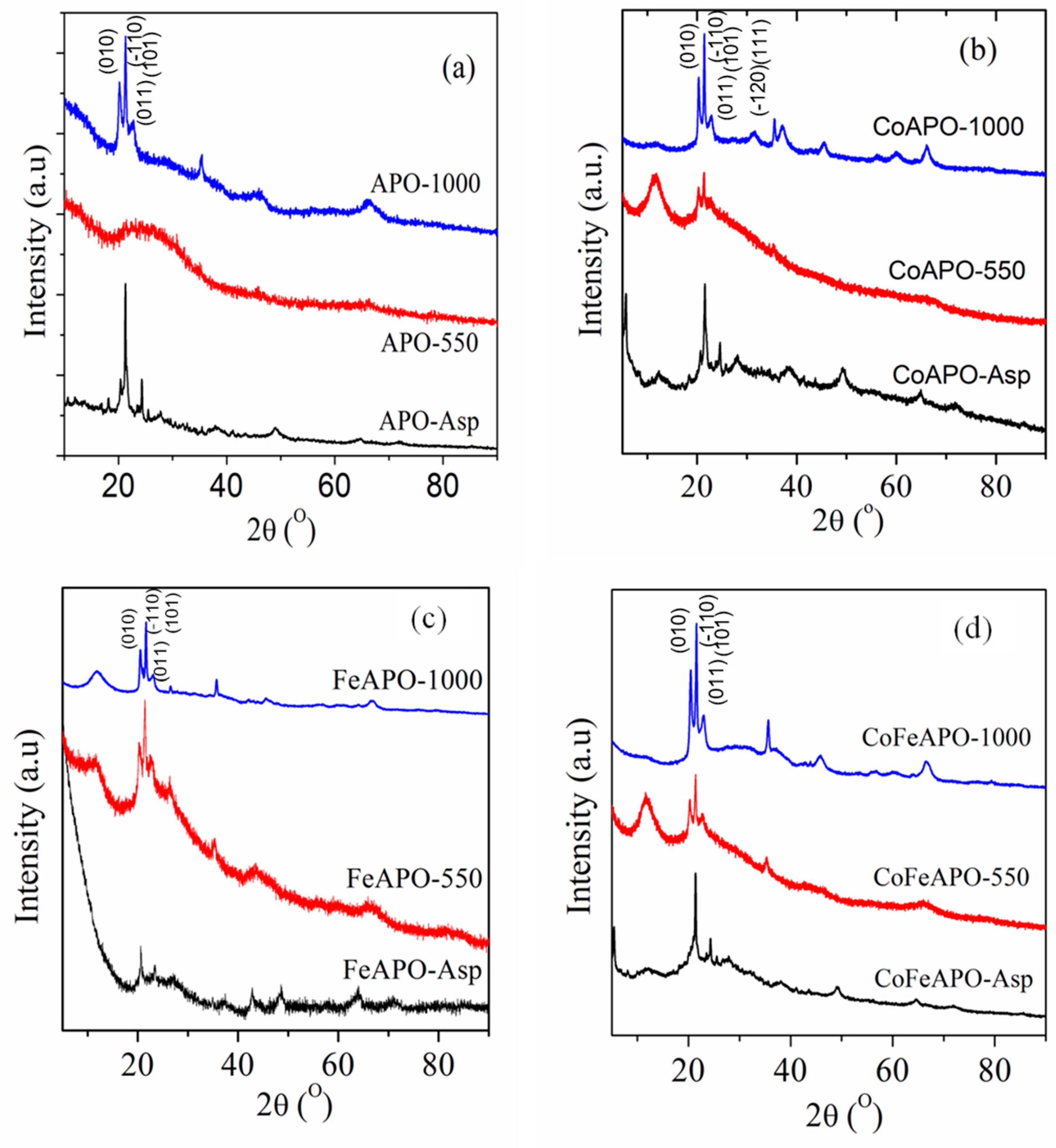
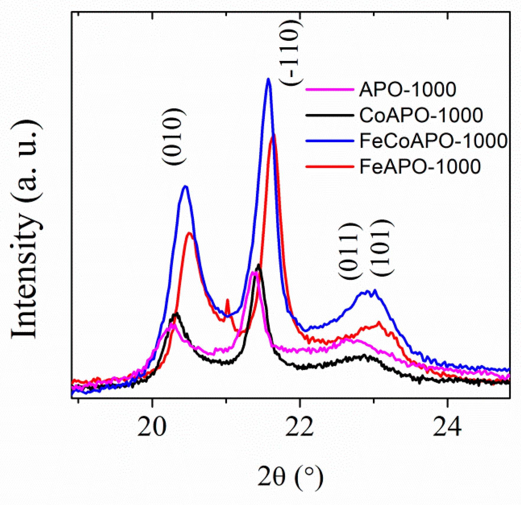
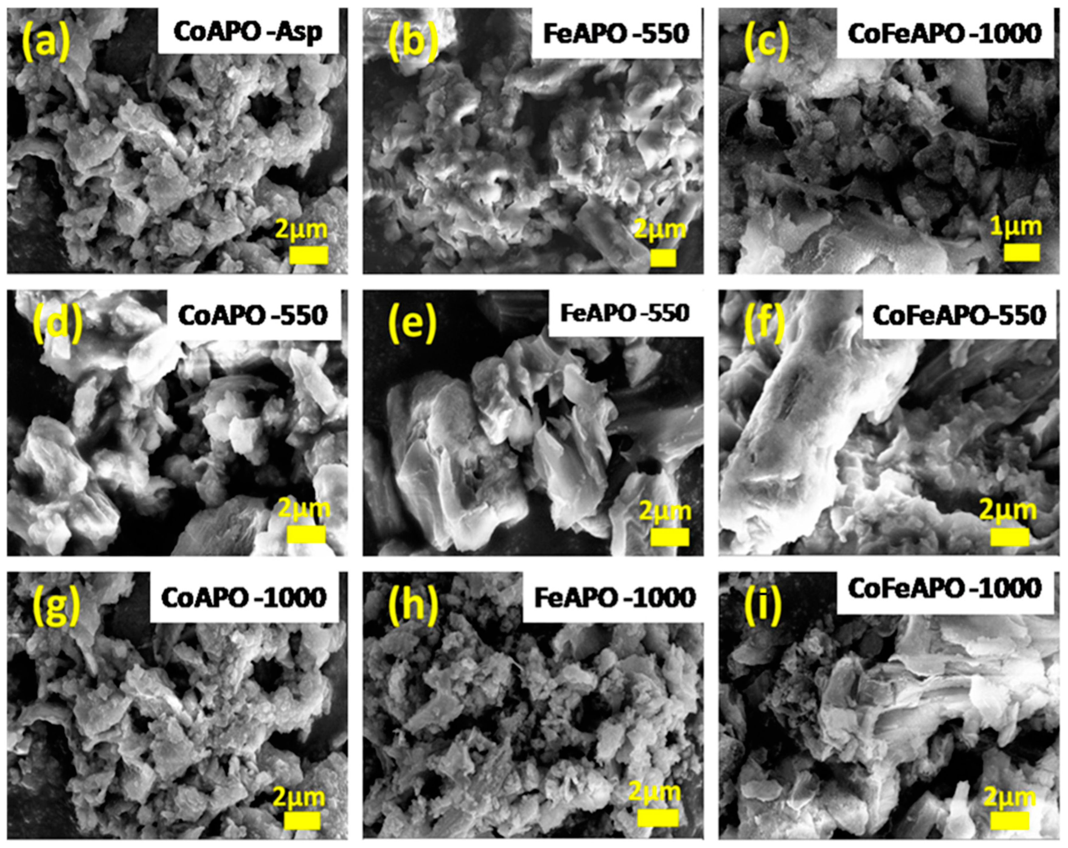
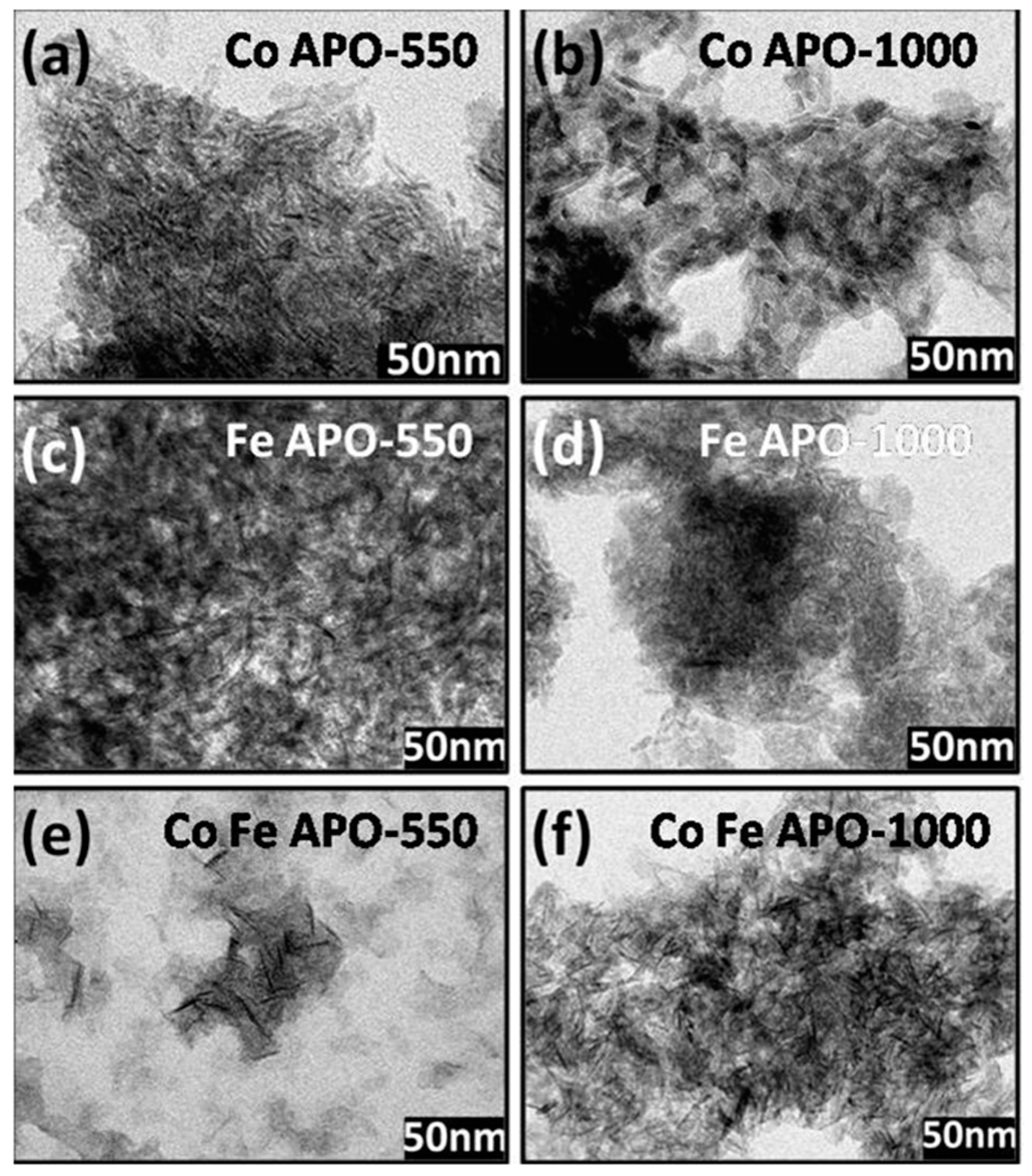
Structure and Properties of Synthesized Samples
3. Photo-Catalytic Activity of the TM-APO Samples for 4-Nitrophenol Reduction
Induction Time and Mechanism of Catalytic Reduction of 4-NP by the TM-APO Samples
4. Experimental Details
5. Conclusions
Supplementary Materials
Author Contributions
Funding
Data Availability Statement
Acknowledgments
Conflicts of Interest
References
- Dapurkar, S.E.; Badamali, S.K.; Sakthivel, A.; Selvam, P. Isomorphous Substitution of Trivalent Iron in Mesoporous MCM-48 Silicate Molecular Sieves: Synthesis, Characterization and Catalytic Properties. Bull. Catal. Soc. India 2005, 4, 63–67. [Google Scholar]
- Corma, A. From Microporous to Mesoporous Molecular Sieve Materials and Their Use in Catalysis. Chem. Rev. 1997, 97, 2373–2420. [Google Scholar] [CrossRef] [PubMed]
- Sakthivel, A.; Selvam, P. Mesoporous (Cr)MCM-41: A Mild and Efficient Heterogeneous Catalyst for Selective Oxidation of Cyclohexane. J. Catal. 2002, 211, 134–143. [Google Scholar] [CrossRef]
- Barton, T.J.; Bull, L.M.; Klemperer, W.G.; Loy, D.A.; McEnaney, B.; Misono, M.; Monson, P.A.; Pez, G.; Scherer, G.W.; Vartuli, J.C.; et al. Tailored Porous Materials. Chem. Mater. 1999, 11, 2633–2656. [Google Scholar] [CrossRef]
- Cheetham, A.K.; Férey, G.; Loiseau, T. Open-Framework Inorganic Materials. Angew. Chem. Int. Ed. 1999, 38, 3268–3292. [Google Scholar] [CrossRef]
- Rajić, N. Open-Framework Aluminophosphates: Synthesis, Characterization and Transition Metal Modifications. J. Serbian Chem. Soc. 2005, 70, 371–391. [Google Scholar] [CrossRef]
- Cardile, C.M.; Tapp, N.J.; Milestone, N.B. Synthesis and Characterization of an Iron-Substituted Aluminophosphate Molecular Sieve. Zeolites 1990, 10, 90–94. [Google Scholar] [CrossRef]
- Shiralkar, V.P.; Saldarriaga, C.H.; Perez, J.O.; Clearfield, A.; Chen, M.; Anthony, R.G.; Donohue, J.A. Synthesis and Characterization of CoAPO-5, a Cobalt-Containing AlPO4-5. Zeolites 1989, 9, 474–482. [Google Scholar] [CrossRef]
- Wang, L.; Tian, B.; Fan, J.; Liu, X.; Yang, H.; Yu, C.; Tu, B.; Zhao, D. Block Copolymer Templating Syntheses of Ordered Large-Pore Stable Mesoporous Aluminophosphates and Fe-Aluminophosphate Based on an “Acid–Base Pair” Route. Microporous Mesoporous Mater. 2004, 67, 123–133. [Google Scholar] [CrossRef]
- Kraushaar-Czarnetzki, B.; Hoogervorst, W.G.M.; Andréa, R.R.; Emeis, C.A.; Stork, W.H.J. Characterisation of CoII and CoIII in CoAPO Molecular Sieves. J. Chem. Soc. Faraday Trans. 1991, 87, 891–895. [Google Scholar] [CrossRef]
- Gu, S.; Wunder, S.; Lu, Y.; Ballauff, M.; Fenger, R.; Rademann, K.; Jaquet, B.; Zaccone, A. Kinetic Analysis of the Catalytic Reduction of 4-Nitrophenol by Metallic Nanoparticles. J. Phys. Chem. C 2014, 118, 18618–18625. [Google Scholar] [CrossRef]
- Sharma, S.; Khare, N. Hierarchical Bi2S3 Nanoflowers: A Novel Photocatalyst for Enhanced Photocatalytic Degradation of Binary Mixture of Rhodamine B and Methylene Blue Dyes and Degradation of Mixture of p-Nitrophenol and p-Chlorophenol. Adv. Powder Technol. 2018, 29, 3336–3347. [Google Scholar] [CrossRef]
- Sharma, M.; Hazra, S.; Basu, S. Synthesis of Heterogeneous Ag-Cu Bimetallic Monolith with Different Mass Ratios and Their Performances for Catalysis and Antibacterial Activity. Adv. Powder Technol. 2017, 28, 3085–3094. [Google Scholar] [CrossRef]
- Anantharamaiah, P.N.; Chandra, N.S.; Shashanka, H.M.; Kumar, R.; Sahoo, B. Magnetic and Catalytic Properties of Cu-Substituted SrFe12O19 Synthesized by Tartrate-Gel Method. Adv. Powder Technol. 2020, 31, 2385–2393. [Google Scholar] [CrossRef]
- Nagamine, S.; Inohara, K. Photocatalytic Microreactor Using Anodized TiO2 Nanotube Array. Adv. Powder Technol. 2018, 29, 3100–3106. [Google Scholar] [CrossRef]
- Liu, J.; Wu, Q.; Huang, F.; Zhang, H.; Xu, S.; Huang, W.; Li, Z. Facile Preparation of a Variety of Bimetallic Dendrites with High Catalytic Activity by Two Simultaneous Replacement Reactions. RSC Adv 2013, 3, 14312–14321. [Google Scholar] [CrossRef]
- Gong, C.; Zhou, Z.; Zhou, H.; Liu, R. Vacuum-Assisted Synthesis of Tiny Au Nanoparticles Entrapped into Mesoporous Carbon Matrix with Superior Catalytic Activity for 4-Nitrophenol Reduction. Adv. Powder Technol. 2019, 30, 649–655. [Google Scholar] [CrossRef]
- Tian, Y.; Cao, Y.Y.; Pang, F.; Chen, G.Q.; Zhang, X. Ag Nanoparticles Supported on N-Doped Graphene Hybrids for Catalytic Reduction of 4-Nitrophenol. RSC Adv. 2014, 4, 43204–43211. [Google Scholar] [CrossRef]
- Kumar Barman, B.; Kar Nanda, K. Uninterrupted Galvanic Reaction for Scalable and Rapid Synthesis of Metallic and Bimetallic Sponges/Dendrites as Efficient Catalysts for 4-Nitrophenol Reduction. Dalton Trans. 2015, 44, 4215–4222. [Google Scholar] [CrossRef]
- Zhou, L.; Xu, J.; Chen, C.; Wang, F.; Li, X. Synthesis of Fe, Co, and Mn Substituted AlPO-5 Molecular Sieves and Their Catalytic Activities in the Selective Oxidation of Cyclohexane. J. Porous Mater. 2008, 15, 7–12. [Google Scholar] [CrossRef]
- Liu, G.; Wang, Z.; Jia, M.; Zou, X.; Zhu, X.; Zhang, W.; Jiang, D. Thermally Stable Amorphous Mesoporous Aluminophosphates with Controllable P/Al Ratio: Synthesis, Characterization, and Catalytic Performance for Selective O-Methylation of Catechol. J. Phys. Chem. B 2006, 110, 16953–16960. [Google Scholar] [CrossRef] [PubMed]
- Gándara, F.; López-Arbeloa, F.; Ruiz-Hitzky, E.; Camblor, M.A. “Bottle-around-a-Ship” Confinement of High Loadings of Acridine Orange in New Aluminophosphate Crystalline Materials. J. Mater. Chem. 2006, 16, 1765–1771. [Google Scholar] [CrossRef]
- Vaughan, D.E.W.; Yennawar, H.P.; Perrottat, A.J. Synthesis and Structure of an Aluminophosphate Built from 3-Rings. Chem. Mater. 2006, 18, 3611–3615. [Google Scholar] [CrossRef]
- Hu, Y.; Navrotsky, A.; Chen, C.Y.; Davis, M.E. Thermochemical Study of the Relative Stability of Dense and Microporous Aluminophosphate Frameworks. Chem. Mater. 1995, 7, 1816–1823. [Google Scholar] [CrossRef]
- Kumar, R.; Rajendiran, R.; Choudhary, H.K.; Naveen, N.K.; Balaiah, B.; Anupama, A.V.; Sahoo, B. Role of Pyrolysis Reaction Temperature and Heating-Rate in the Growth and Morphology of Carbon Nanostructures. Nano-Struct. Nano-Objects 2017, 12, 229–238. [Google Scholar] [CrossRef]
- Kumar, R.; Anupama, A.V.; Kumaran, V.; Sahoo, B. Effect of Solvents on the Structure and Magnetic Properties of Pyrolysis Derived Carbon Globules Embedded with Iron/Iron Carbide Nanoparticles and Their Applications in Magnetorheological Fluids. Nano-Struct. Nano-Objects 2018, 16, 167–173. [Google Scholar] [CrossRef]
- Kumar, R.; Sahoo, B. Carbon Nanotubes or Carbon Globules: Optimization of the Pyrolytic Synthesis Parameters and Study of the Magnetic Properties. Nano-Struct. Nano-Objects 2018, 14, 131–137. [Google Scholar] [CrossRef]
- Kumar, R.; Sahoo, B. One-Step Pyrolytic Synthesis and Growth Mechanism of Core–Shell Type Fe/Fe3C-Graphite Nanoparticles-Embedded Carbon Globules. Nano-Struct. Nano-Objects 2018, 16, 77–85. [Google Scholar] [CrossRef]
- Choudhary, H.K.; Kumar, R.; Pawar, S.P.; Sundararaj, U.; Sahoo, B. Effect of Morphology and Role of Conductivity of Embedded Metallic Nanoparticles on Electromagnetic Interference Shielding of PVDF-Carbonaceous-Nanofiller Composites. Carbon 2020, 164, 357–368. [Google Scholar] [CrossRef]
- Kumar, R.; Kumar, A.; Verma, N.; Khopkar, V.; Philip, R.; Sahoo, B. Ni Nanoparticles Coated with Nitrogen-Doped Carbon for Optical Limiting Applications. ACS Appl. Nano Mater. 2020, 3, 8618–8631. [Google Scholar] [CrossRef]
- Kumar, R.; Choudhary, H.K.; Anupama, A.V.; Menon, A.V.; Pawar, S.P.; Bose, S.; Sahoo, B. Nitrogen Doping as a Fundamental Way to Enhance the EMI Shielding Behavior of Cobalt Particle-Embedded Carbonaceous Nanostructures. New J. Chem. 2019, 43, 5568–5580. [Google Scholar] [CrossRef]
- Kumar, R.; Kumar, A.; Verma, N.; Anupama, A.V.; Philip, R.; Sahoo, B. Modulating Non-Linear Optical Absorption through Controlled Graphitization of Carbon Nanostructures Containing Fe3C-Graphite Core-Shell Nanoparticles. Carbon 2019, 153, 545–556. [Google Scholar] [CrossRef]
- Kumar, R.; Kumar, A.; Verma, N.; Philip, R.; Sahoo, B. Mechanistic Insights into the Optical Limiting Performance of Carbonaceous Nanomaterials Embedded with Core-Shell Type Graphite Encapsulated Co Nanoparticles. Phys. Chem. Chem. Phys. 2020, 22, 27224–27240. [Google Scholar] [CrossRef] [PubMed]
- Kumar, R.; Kumar, A.; Verma, N.; Philip, R.; Sahoo, B. FeCoCr Alloy-Nanoparticle Embedded Bamboo-Type Carbon Nanotubes for Non-Linear Optical Limiting Application. J. Alloys Compd. 2020, 849, 156665. [Google Scholar] [CrossRef]
- Yadav, A.; Kumar, R.; Choudhary, H.K.; Sahoo, B. Graphene-Oxide Coating for Corrosion Protection of Iron Particles in Saline Water. Carbon 2018, 140, 477–487. [Google Scholar] [CrossRef]
- Yadav, A.; Kumar, R.; Sahoo, B. Graphene Oxide Coatings on Amino Acid Modified Fe Surfaces for Corrosion Inhibition. ACS Appl. Nano Mater. 2020, 3, 3540–3557. [Google Scholar] [CrossRef]
- Yadav, A.; Kumar, R.; Pandey, U.P.; Sahoo, B. Role of Oxygen Functionalities of GO in Corrosion Protection of Metallic Fe. Carbon 2021, 173, 350–363. [Google Scholar] [CrossRef]
- Kumar, R.; Manjunatha, M.; Anupama, A.V.; Ramesh, K.P.; Sahoo, B. Synthesis, Composition and Spin-Dynamics of FCC and HCP Phases of Pyrolysis Derived Co-Nanoparticles Embedded in Amorphous Carbon Matrix. Ceram. Int. 2019, 45, 19879–19887. [Google Scholar] [CrossRef]
- Kumar, R.; Sahoo, B. Investigation of Disorder in Carbon Encapsulated Core-Shell Fe/Fe3C Nanoparticles Synthesized by One-Step Pyrolysis. Diam. Relat. Mater. 2018, 90, 62–71. [Google Scholar] [CrossRef]
- Choudhary, H.K.; Kumar, R.; Pawar, S.P.; Sundararaj, U.; Sahoo, B. Enhancing Absorption Dominated Microwave Shielding in Co@C-PVDF Nanocomposites through Improved Magnetization and Graphitization of the Co@C-Nanoparticles. Phys. Chem. Chem. Phys. 2019, 21, 15595–15608. [Google Scholar] [CrossRef]
- Kumar, R.; Khan, M.A.; Anupama, A.V.; Krupanidhi, S.B.; Sahoo, B. Infrared Photodetectors Based on Multiwalled Carbon Nanotubes: Insights into the Effect of Nitrogen Doping. Appl. Surf. Sci. 2021, 538, 148187. [Google Scholar] [CrossRef]
- Kumar, R.; Choudhary, H.K.; Pawar, S.P.; Bose, S.; Sahoo, B. Carbon Encapsulated Nanoscale Iron/Iron-Carbide/Graphite Particles for EMI Shielding and Microwave Absorption. Phys. Chem. Chem. Phys. 2017, 19, 23268–23279. [Google Scholar] [CrossRef] [PubMed]
- Mahour, L.N.; Choudhary, H.K.; Kumar, R.; Anupama, A.V.; Sahoo, B. Structural, Optical and Mössbauer Spectroscopic Investigations on the Environment of Fe in Fe-Doped ZnO (Zn1-XFexO) Ceramics Synthesized by Solution Combustion Method. Ceram. Int. 2019, 45, 24625–24634. [Google Scholar] [CrossRef]
- Mohapatra, S.K.; Sahoo, B.; Keune, W.; Selvam, P. Synthesis, Characterization and Catalytic Activity of Mesoporous Trivalent Iron Substituted Aluminophosphates. Chem. Commun. 2002, 223, 1466–1467. [Google Scholar] [CrossRef] [PubMed]
- Anupama, A.V.; Kumar, R.; Choudhary, H.K.; Sahoo, B. Synthesis of Coral-Shaped Yttrium-Aluminium-Iron Garnets by Solution-Combustion Method. Ceram. Int. 2018, 44, 3024–3031. [Google Scholar] [CrossRef]
- Choudhary, H.K.; Kumar, R.; Pawar, S.P.; Anupama, A.V.; Bose, S.; Sahoo, B. Effect of Coral-Shaped Yttrium Iron Garnet Particles on the EMI Shielding Behaviour of Yttrium Iron Garnet-Polyaniline-Wax Composites. ChemistrySelect 2018, 3, 2120–2130. [Google Scholar] [CrossRef]
- Anupama, A.V.; Choudhary, H.K.; Kumar, R.; Kumaran, V.; Sahoo, B. Steady-Shear Response of Magnetorheological Fluid Containing Coral-Shaped Yttrium-Iron-Garnet Particles. Mater. Res. Bull. 2019, 113, 45–50. [Google Scholar] [CrossRef]
- Khassin, A.A.; Yurieva, T.M.; Kaichev, V.V.; Bukhtiyarov, V.I.; Budneva, A.A.; Paukshtis, E.A.; Parmon, V.N. Metal–Support Interactions in Cobalt-Aluminum Co-Precipitated Catalysts: XPS and CO Adsorption Studies. J. Mol. Catal. A Chem. 2001, 175, 189–204. [Google Scholar] [CrossRef]
- Khassin, A.A.; Yurieva, T.M.; Kustova, G.N.; Plyasova, L.M.; Itenberg, I.S.; Demeshkina, M.P.; Chermashentseva, G.K.; Anufrienko, V.F.; Zaikovskii, V.I.; Larina, T.V.; et al. Cobalt-Containing Catalysts Supported by Synthetic Zn- and Mg-Stevensites and Their Performance in the Fischer–Tropsch Synthesis. J. Mol. Catal. A Chem. 2001, 168, 209–224. [Google Scholar] [CrossRef]
- Kungurova, O.A.; Khassin, A.A.; Cherepanova, S.V.; Saraev, A.A.; Kaichev, V.V.; Shtertser, N.V.; Chermashentseva, G.K.; Gerasimov, Е.Y.; Paukshtis, Е.A.; Vodyankina, О.V.; et al. δ-Alumina Supported Cobalt Catalysts Promoted by Ruthenium for Fischer-Tropsch Synthesis. Appl. Catal. A Gen. 2017, 539, 48–58. [Google Scholar] [CrossRef]
- Grandjean, D.; Pelipenko, V.; Batyrev, E.D.; van den Heuvel, J.C.; Khassin, A.A.; Yurieva, T.M.; Weckhuysen, B.M. Dynamic Cu/Zn Interaction in SiO2 Supported Methanol Synthesis Catalysts Unraveled by in Situ XAFS. J. Phys. Chem. C 2011, 115, 20175–20191. [Google Scholar] [CrossRef]
- Kumar, R.; Kumar, S.; Chandrappa, S.G.; Goyal, N.; Yadav, A.; Ravishankar, N.; Prakash, A.S.; Sahoo, B. Nitrogen-Doped Carbon Nanostructures Embedded with Fe-Co-Cr Alloy Based Nanoparticles as Robust Electrocatalysts for Zn-Air Batteries. J. Alloys Compd. 2024, 984, 173862. [Google Scholar] [CrossRef]
- Kumar, S.; Kumar, R.; Goyal, N.; Vazhayil, A.; Yadav, A.; Thomas, N.; Sahoo, B. N-Doped Carbon Nanotubes Nucleated through Cobalt Nanoparticles as Bifunctional Catalysts for Zinc–Air Batteries. ACS Appl. Nano Mater. 2024, 7, 7865–7882. [Google Scholar] [CrossRef]
- Kumar, A.; Kumar, R.; Verma, N.; Anupama, A.V.; Choudhary, H.K.; Philip, R.; Sahoo, B. Effect of the Band Gap and the Defect States Present within Band Gap on the Non-Linear Optical Absorption Behaviour of Yttrium Aluminium Iron Garnets. Opt. Mater. 2020, 108, 110163. [Google Scholar] [CrossRef]
- Choudhary, H.K.; Kumar, R.; Patangrao, S.; Sahoo, B. Role of Graphitization-Controlled Conductivity in Enhancing Absorption Dominated EMI Shielding Behavior of Pyrolysis-Derived Fe3C@C-PVDF Nanocomposites. Mater. Chem. Phys. 2021, 263, 124429. [Google Scholar] [CrossRef]
- Chrétien, M.N.; Heafey, E.; Scaiano, J.C. Reducing Adverse Effects from UV Sunscreens by Zeolite Encapsulation: Comparison of Oxybenzone in Solution and in Zeolites. Photochem. Photobiol. 2010, 86, 153–161. [Google Scholar] [CrossRef]
- Jiménez, J.A. Optical Properties of Eu3+-Doped Aluminophosphate Glass with a High Concentration of Silver and Tin. J. Inorg. Organomet. Polym. Mater. 2017, 27, 372–379. [Google Scholar] [CrossRef]
- Yang, L.; Kruse, B. Revised Kubelka—Munk Theory I. Theory. J. Opt. Soc. Am. 2004, 21, 1933–1941. [Google Scholar] [CrossRef] [PubMed]
- Kokhanovsky, A.A. Physical Interpretation and Accuracy of the Kubelka-Munk Theory. J. Phys. D Appl. Phys. 2007, 40, 2210–2216. [Google Scholar] [CrossRef]
- Tamon, H.; Ishizaka, H.; Yamamoto, T.; Suzuki, T. Preparation of Mesoporous Carbon by Freeze Drying. Carbon 1999, 37, 2049–2055. [Google Scholar] [CrossRef]
- Saha, D.; Deng, S. Adsorption Equilibrium and Kinetics of CO2, CH4, N2O, and NH3 on Ordered Mesoporous Carbon. J. Colloid Interface Sci. 2010, 345, 402–409. [Google Scholar] [CrossRef] [PubMed]
- Nivetha, R.; Asrami, M.R.; Kumar, R.; Sharma, S.; Jourshabani, M.; Kumar, R.D.; Ravichandran, S.; Lee, B.; Lee, Y.; Chung, J.S.; et al. Highly Immobilized Bimetallic Fe/M-N4 (M- Mg or Zn) Conductive Metal–Organic Frameworks on Nitrogen-Doped Porous Carbon for Efficient Electrocatalytic Hydrogen Evolution and Oxygen Reduction Reactions. Small Struct. 2024, 5, 2300355. [Google Scholar] [CrossRef]
- Georgiou, E. Catalytic Carbon-Carbon Coupling and Reduction Using Crystalline Porous Solids for Sustainability and Environmental Applications. Doctoral Dissertation, University of Southampton, Southampton, UK, 2017. [Google Scholar]
- Mohapatra, S.K.; Sonavane, S.U.; Jayaram, R.V.; Selvam, P. Heterogeneous Catalytic Transfer Hydrogenation of Aromatic Nitro and Carbonyl Compounds over Cobalt(II) Substituted Hexagonal Mesoporous Aluminophosphate Molecular Sieves. Tetrahedron Lett. 2002, 43, 8527–8529. [Google Scholar] [CrossRef]
- Maharana, R.; Bhanu Prasad, V.V.; Roy, S.; Prasad, D.; Kumar, K.; Paik, P.; Hebalkar, N.; Shukla, A.; Bal, R. Synthesis of High Temperature Stable Carbon Coated Metal Nanoparticles in AlPO4 Based Matrix in Situ in Oxidative Atmosphere. J. Am. Ceram. Soc. 2016, 99, 64–71. [Google Scholar] [CrossRef]
- Shi, Q.-x.; Lv, R.-w.; Zhang, Z.-x.; Zhao, D.-f. Advances in Heterogeneous Catalytic Transfer Hydrogenation of Aromatic Nitro Compounds. In Proceedings of the 3rd International Conference on Functional Molecules Compounds, Dalian, China, 8–11 September 2005; pp. 54–58. [Google Scholar]
- Mohapatra, S.K.; Sonavane, S.U.; Jayaram, R.V.; Selvam, P. Reductive Cleavage of Azo Dyes and Reduction of Nitroarenes over Trivalent Iron Incorporated Hexagonal Mesoporous Aluminophosphate Molecular Sieves. Appl. Catal. B 2003, 46, 155–163. [Google Scholar] [CrossRef]
- Selvam, P.; Mohapatra, S.K.; Sonavane, S.U.; Jayaram, R.V. Chemo- and Regioselective Reduction of Nitroarenes, Carbonyls and Azo Dyes over Nickel-Incorporated Hexagonal Mesoporous Aluminophosphate Molecular Sieves. Tetrahedron Lett. 2004, 45, 2003–2007. [Google Scholar] [CrossRef]
- Rout, L.; Kumar, A.; Dhaka, R.S.; Reddy, G.N.; Giri, S.; Dash, P. Bimetallic Au-Cu Alloy Nanoparticles on Reduced Graphene Oxide Support: Synthesis, Catalytic Activity and Investigation of Synergistic Effect by DFT Analysis. Appl. Catal. A Gen. 2017, 538, 107–122. [Google Scholar] [CrossRef]
- Menumerov, E.; Hughes, R.A.; Golze, S.D.; Neal, R.D.; Demille, T.B.; Campanaro, J.C.; Kotesky, K.C.; Rouvimov, S.; Neretina, S. Identifying the True Catalyst in the Reduction of 4-Nitrophenol: A Case Study Showing the Effect of Leaching and Oxidative Etching Using Ag Catalysts. ACS Catal. 2018, 8, 8879–8888. [Google Scholar] [CrossRef]
- Wunder, S.; Polzer, F.; Lu, Y.; Mei, Y.; Ballauff, M. Kinetic Analysis of Catalytic Reduction of 4-Nitrophenol by Metallic Nanoparticles Immobilized in Spherical Polyelectrolyte Brushes. J. Phys. Chem. C 2010, 114, 8814–8820. [Google Scholar] [CrossRef]
- Kong, X.K.; Sun, Z.Y.; Chen, M.; Chen, C.L.; Chen, Q.W. Metal-Free Catalytic Reduction of 4-Nitrophenol to 4-Aminophenol by N-Doped Graphene. Energy Env. Sci 2013, 6, 3260–3266. [Google Scholar] [CrossRef]
- Gao, L.; Li, R.; Sui, X.; Li, R.; Chen, C.; Chen, Q. Conversion of Chicken Feather Waste to N-Doped Carbon Nanotubes for the Catalytic Reduction of 4-Nitrophenol. Environ. Sci. Technol. 2014, 48, 10191–10197. [Google Scholar] [CrossRef] [PubMed]
- Menumerov, E.; Hughes, R.A.; Neretina, S. Catalytic Reduction of 4-Nitrophenol: A Quantitative Assessment of the Role of Dissolved Oxygen in Determining the Induction Time. Nano Lett. 2016, 16, 7791–7797. [Google Scholar] [CrossRef] [PubMed]
- Koklioti, M.A.; Skaltsas, T.; Sato, Y.; Suenaga, K.; Stergiou, A.; Tagmatarchis, N. Mechanistic Insights into the Photocatalytic Properties of Metal Nanocluster/Graphene Ensembles. Examining the Role of Visible Light in the Reduction of 4-Nitrophenol. Nanoscale 2017, 9, 9685–9692. [Google Scholar] [CrossRef] [PubMed]
- Yang, T.Q.; Ning, T.Y.; Peng, B.; Shan, B.Q.; Zong, Y.X.; Hao, P.; Yuan, E.H.; Chen, Q.M.; Zhang, K. Interfacial Electron Transfer Promotes Photo-Catalytic Reduction of 4-Nitrophenol by Au/Ag2O Nanoparticles Confined in Dendritic Mesoporous Silica Nanospheres. Catal. Sci. Technol. 2019, 9, 5786–5792. [Google Scholar] [CrossRef]
- Ciganda, R.; Li, N.; Deraedt, C.; Gatard, S.; Zhao, P.; Salmon, L.; Hernández, R.; Ruiz, J.; Astruc, D. Gold Nanoparticles as Electron Reservoir Redox Catalysts for 4-Nitrophenol Reduction: A Strong Stereoelectronic Ligand Influence. Chem. Commun. 2014, 50, 10126–10129. [Google Scholar] [CrossRef] [PubMed]
- Qian, J.; Yuan, A.; Yao, C.; Liu, J.; Li, B.; Xi, F.; Dong, X. Highly Efficient Photo-Reduction of p-Nitrophenol by Protonated Graphitic Carbon Nitride Nanosheets. ChemCatChem 2018, 10, 4747–4754. [Google Scholar] [CrossRef]
- Miah, A.T.; Malakar, B.; Saikia, P. Gold over Ceria-Titania Mixed Oxides: Solar Light Induced Catalytic Activity for Nitrophenol Reduction. Catal. Lett. 2016, 146, 291–303. [Google Scholar] [CrossRef]
- Bekena, F.T.; Abdullah, H.; Kuo, D.H.; Zeleke, M.A. Photocatalytic Reduction of 4-Nitrophenol Using Effective Hole Scavenger over Novel Mg-Doped Zn(O,S) Nanoparticles. J. Ind. Eng. Chem. 2019, 78, 116–124. [Google Scholar] [CrossRef]
- Liu, X.; Zhao, L.; Lai, H.; Zhang, X.; Yi, Z. Highly Effective Degradation of P-Nitrophenol Over MoS2 Under Visible Light Illumination. Catal Lett. 2017, 147, 2153–2159. [Google Scholar] [CrossRef]
- Chen, Y.; Sun, F.; Huang, Z.; Chen, H.; Zhuang, Z.; Pan, Z.; Long, J.; Gu, F. Photochemical Fabrication of SnO2 Dense Layers on Reduced Graphene Oxide Sheets for Application in Photocatalytic Degradation of P-Nitrophenol. Appl. Catal. B 2017, 215, 8–17. [Google Scholar] [CrossRef]
- Sahu, K.; Singh, J.; Mohapatra, S. Catalytic Reduction of 4-Nitrophenol and Photocatalytic Degradation of Organic Pollutants in Water by Copper Oxide Nanosheets. Opt. Mater. 2019, 93, 58–69. [Google Scholar] [CrossRef]
- Zhao, S.; Ma, H.; Wang, M.; Cao, C.; Xiong, J.; Xu, Y.; Yao, S. Study on the Mechanism of Photo-Degradation of p-Nitrophenol Exposed to 254 nm UV Light. J. Hazard. Mater. 2010, 180, 86–90. [Google Scholar] [CrossRef] [PubMed]
- Zhao, Y.; Li, R.; Jiang, P.; Zhang, K.; Dong, Y.; Xie, W. Mechanistic Study of Catalytic Hydride Reduction of -NO2 to -NH2 Using Isotopic Solvent and Reducer: The Real Hydrogen Source. J. Phys. Chem. C 2019, 123, 15582–15588. [Google Scholar] [CrossRef]
- Fountoulaki, S.; Daikopoulou, V.; Gkizis, P.L.; Tamiolakis, I.; Armatas, G.S.; Lykakis, I.N. Mechanistic Studies of the Reduction of Nitroarenes by NaBH4 or Hydrosilanes Catalyzed by Supported Gold Nanoparticles. ACS Catal. 2014, 4, 3504–3511. [Google Scholar] [CrossRef]
- Nemanashi, M.; Meijboom, R. Synthesis and Characterization of Cu, Ag and Au Dendrimer-Encapsulated Nanoparticles and Their Application in the Reduction of 4-Nitrophenol to 4-Aminophenol. J. Colloid Interface Sci. 2013, 389, 260–267. [Google Scholar] [CrossRef] [PubMed]
- Wunder, S.; Lu, Y.; Albrecht, M.; Ballauff, M. Catalytic Activity of Faceted Gold Nanoparticles Studied by a Model Reaction: Evidence for Substrate-Induced Surface Restructuring. ACS Catal. 2011, 1, 908–916. [Google Scholar] [CrossRef]
- Morales, M.V.; Rocha, M.; Freire, C.; Asedegbega-Nieto, E.; Gallegos-Suarez, E.; Rodríguez-Ramos, I.; Guerrero-Ruiz, A. Development of Highly Efficient Cu versus Pd Catalysts Supported on Graphitic Carbon Materials for the Reduction of 4-Nitrophenol to 4-Aminophenol at Room Temperature. Carbon 2017, 111, 150–161. [Google Scholar] [CrossRef]


| Sample | Isomer Shift (δ) (mm/s) | Quadrupole Splitting (Δ) (mm/s) | Peak Line Width (Γ) |
|---|---|---|---|
| Fe-APO-1000 | 0.180 | 0.835 | 0.564 |
| CoFe-APO-1000 | 0.160 | 1.018 | 0.641 |
| Sample Name | Pyrolyzed at 550 °C | Calcined at 1000 °C |
|---|---|---|
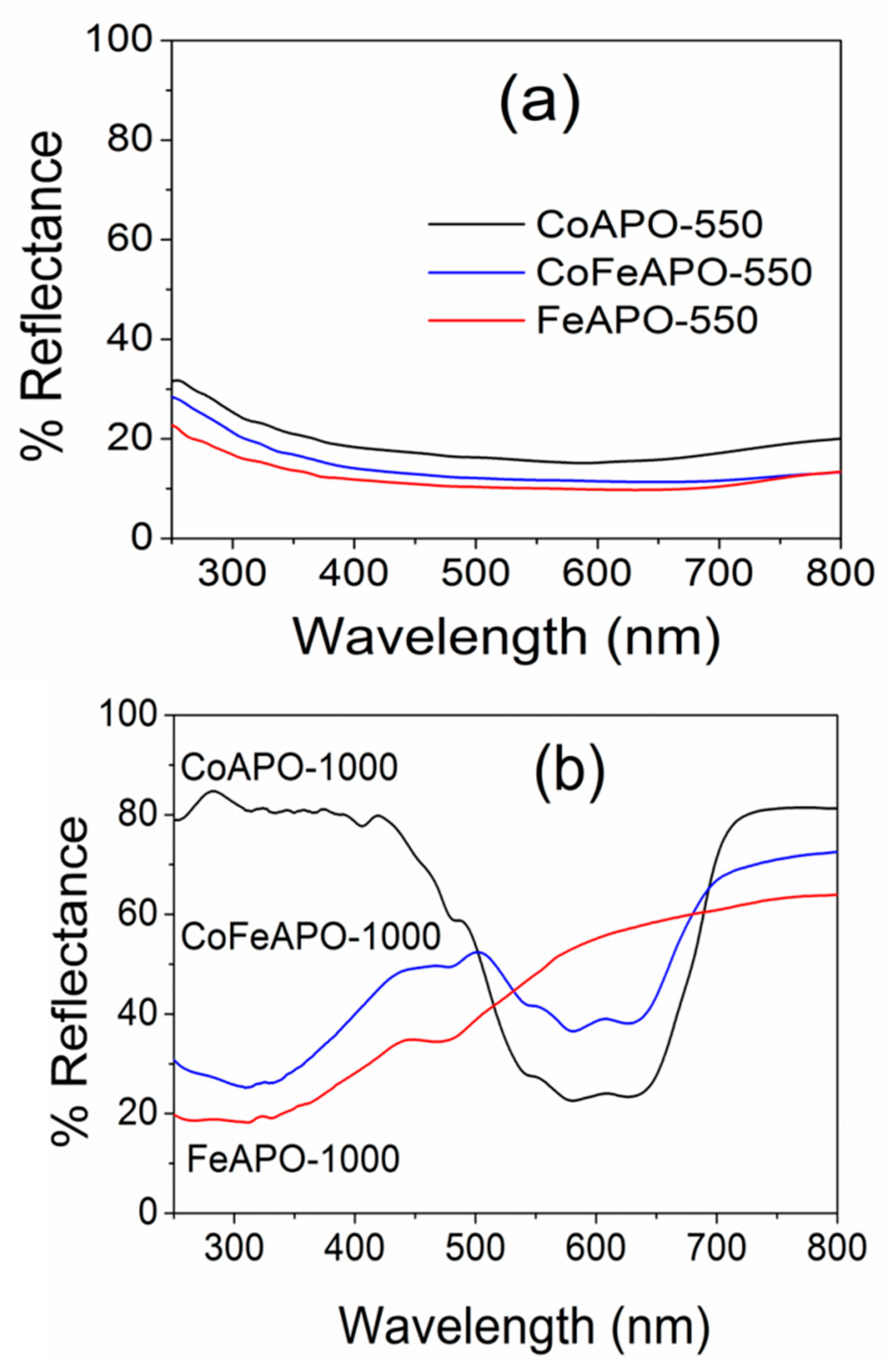
| Band Gap (eV) | Band Gap (eV) | |
| CoAPO | 1.47 | 1.86 |
| FeAPO | 1.48 | 3.04 |
| CoFeAPO | 1.34 | 3.13(1.84) * |
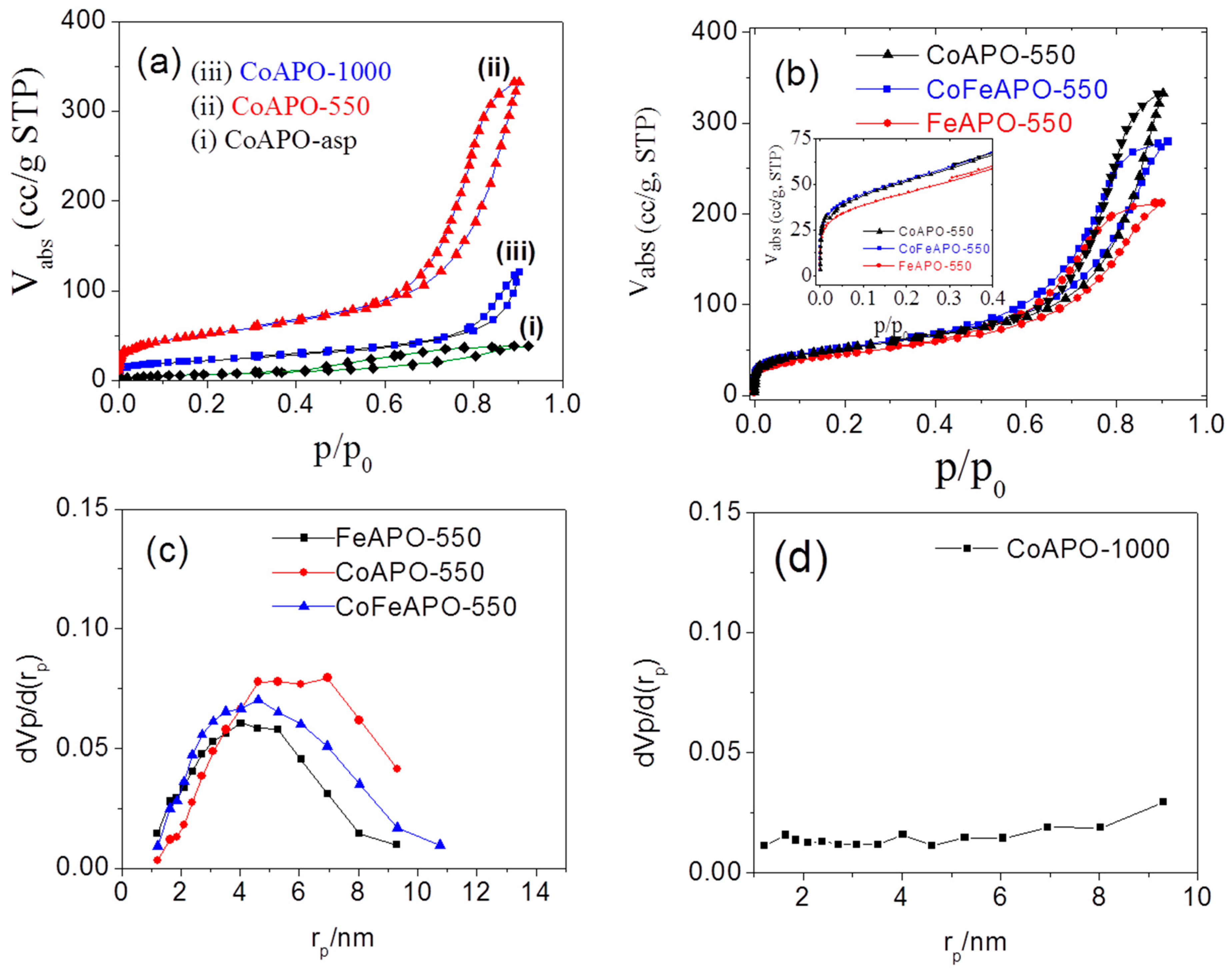
| Sample | Specific Surface Area (m2/g) | Total Pore Volume (cm3/g) | Vm (cm3 /g, (STP)) | Mean Pore Diameter (nm) |
|---|---|---|---|---|
| CoAPO-asp | 26.3 | 0.06 | 6.04 | 8.99 |
| CoAPO-550 | 168.9 | 0.51 | 38.82 | 12.17 |
| FeAPO-550 | 152.9 | 0.33 | 35.14 | 8.57 |
| CoFeAPO- 550 | 171.1 | 0.43 | 39.31 | 10.11 |
| CoAPO-1000 | 72.8 | 0.19 | 16.73 | 10.19 |
| Sample | Vp (cm3/g) | Sp (m2/g) | rp (nm) |
|---|---|---|---|
| CoAPO-as | 0.0624 | 0.0359 | 2.39 |
| CoAPO-550 | 0.4919 | 0.1930 | 6.96 |
| FeAPO-550 | 0.3170 | 0.1663 | 4.02 |
| CoFeAPO-550 | 0.4218 | 0.1956 | 4.60 |
| CoAPO-1000 | 0.1553 | 0.0070 | 9.30 |
| Sample | Dark | Light | Light + Pre-Stirring | ||||||
|---|---|---|---|---|---|---|---|---|---|
| It (min) | Ka (min−1) | % Conversion | It (min) | Ka (min−1) | % Conversion | It (min) | Ka (min−1) | % Conversion | |
| CoAPO-550 | 5 | −0.066 | 97 | 2 | −0.126 | 100 | - | - | - |
| FeAPO-550 | 15 | −0.010 | 52 | 15 | −0.010 | 49 | - | - | - |
| CoFeAPO-550 | 15 | −0.011 | 62 | 10 | −0.053 | 99 | - | - | - |
| CoAPO-1000 | 27 | −0.028 | 84 | 9 | −0.058 (−0.039) | 94 | - | −0.235 (−0.043) | 100 |
| FeAPO-1000 | 52 | −0.034 | 71 | 33 | −0.011 | 91 | 12 | −0.074 | 100 |
| CoFeAPO-1000 | 9 | −0.004 | 42 | 10 | −0.021 | 90 | 9 | −0.061 | 100 |
Disclaimer/Publisher’s Note: The statements, opinions and data contained in all publications are solely those of the individual author(s) and contributor(s) and not of MDPI and/or the editor(s). MDPI and/or the editor(s) disclaim responsibility for any injury to people or property resulting from any ideas, methods, instructions or products referred to in the content. |
© 2024 by the authors. Licensee MDPI, Basel, Switzerland. This article is an open access article distributed under the terms and conditions of the Creative Commons Attribution (CC BY) license (https://creativecommons.org/licenses/by/4.0/).
Share and Cite
Swetha, B.M.; Kumar, R.; A. V., A.; Kumar, S.; Yan, F.; Sahoo, B. Photocatalytic 4-Nitrophenol Reduction by Hydrothermally Synthesized Mesoporous Co- and/or Fe-Substituted Aluminophosphates. Catalysts 2024, 14, 408. https://doi.org/10.3390/catal14070408
Swetha BM, Kumar R, A. V. A, Kumar S, Yan F, Sahoo B. Photocatalytic 4-Nitrophenol Reduction by Hydrothermally Synthesized Mesoporous Co- and/or Fe-Substituted Aluminophosphates. Catalysts. 2024; 14(7):408. https://doi.org/10.3390/catal14070408
Chicago/Turabian StyleSwetha, B. M., Rajeev Kumar, Anupama A. V., Sarvesh Kumar, Fei Yan, and Balaram Sahoo. 2024. "Photocatalytic 4-Nitrophenol Reduction by Hydrothermally Synthesized Mesoporous Co- and/or Fe-Substituted Aluminophosphates" Catalysts 14, no. 7: 408. https://doi.org/10.3390/catal14070408
APA StyleSwetha, B. M., Kumar, R., A. V., A., Kumar, S., Yan, F., & Sahoo, B. (2024). Photocatalytic 4-Nitrophenol Reduction by Hydrothermally Synthesized Mesoporous Co- and/or Fe-Substituted Aluminophosphates. Catalysts, 14(7), 408. https://doi.org/10.3390/catal14070408