
Recent Progress on Tailoring the Biomass-Derived Cellulose Hybrid Composite Photocatalysts
 ,
,  ,
,  ,
,  and
and
Abstract
:1. Introduction
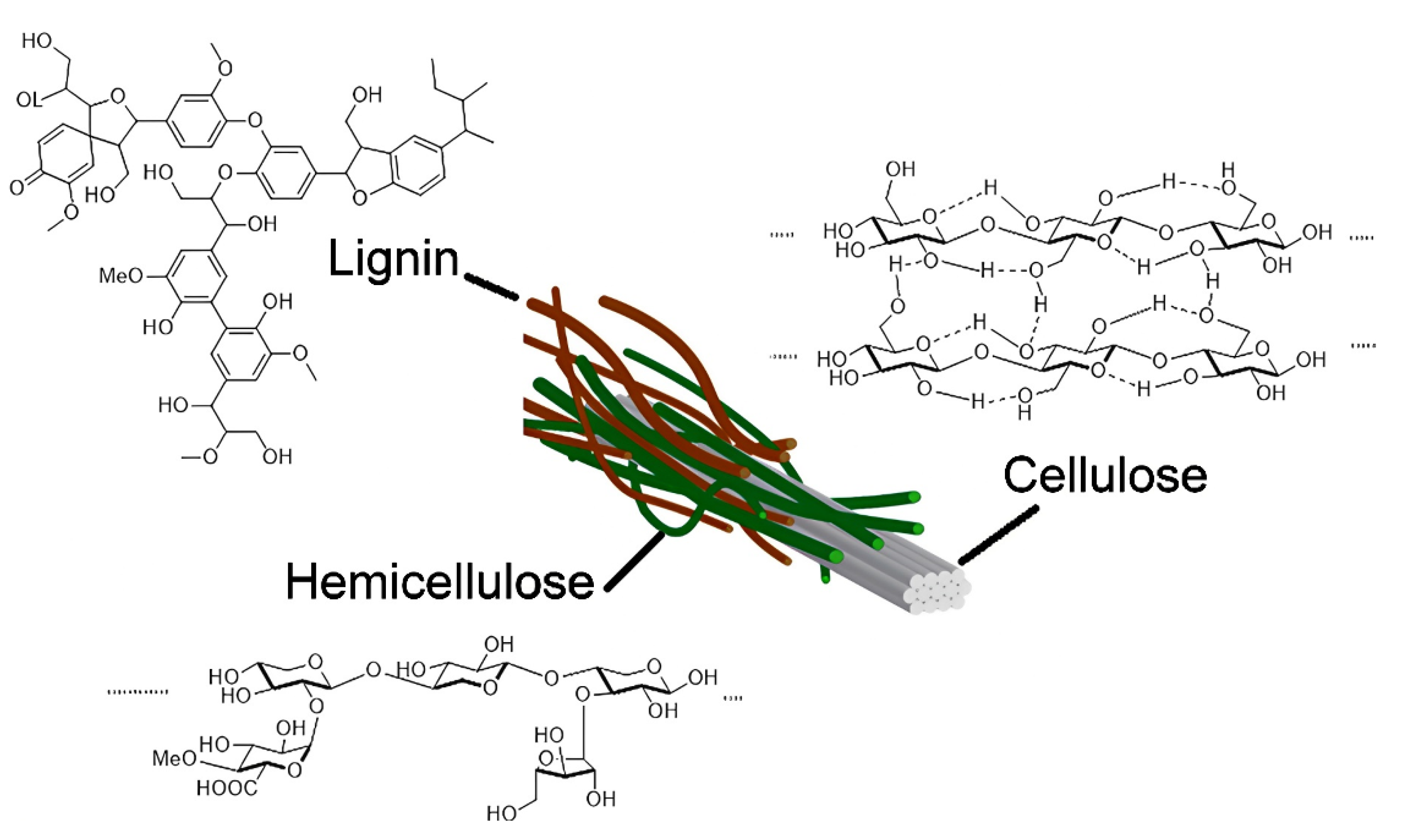
2. Biomass
2.1. Biochar
2.2. Activated Carbon (AC)
2.3. Cellulose
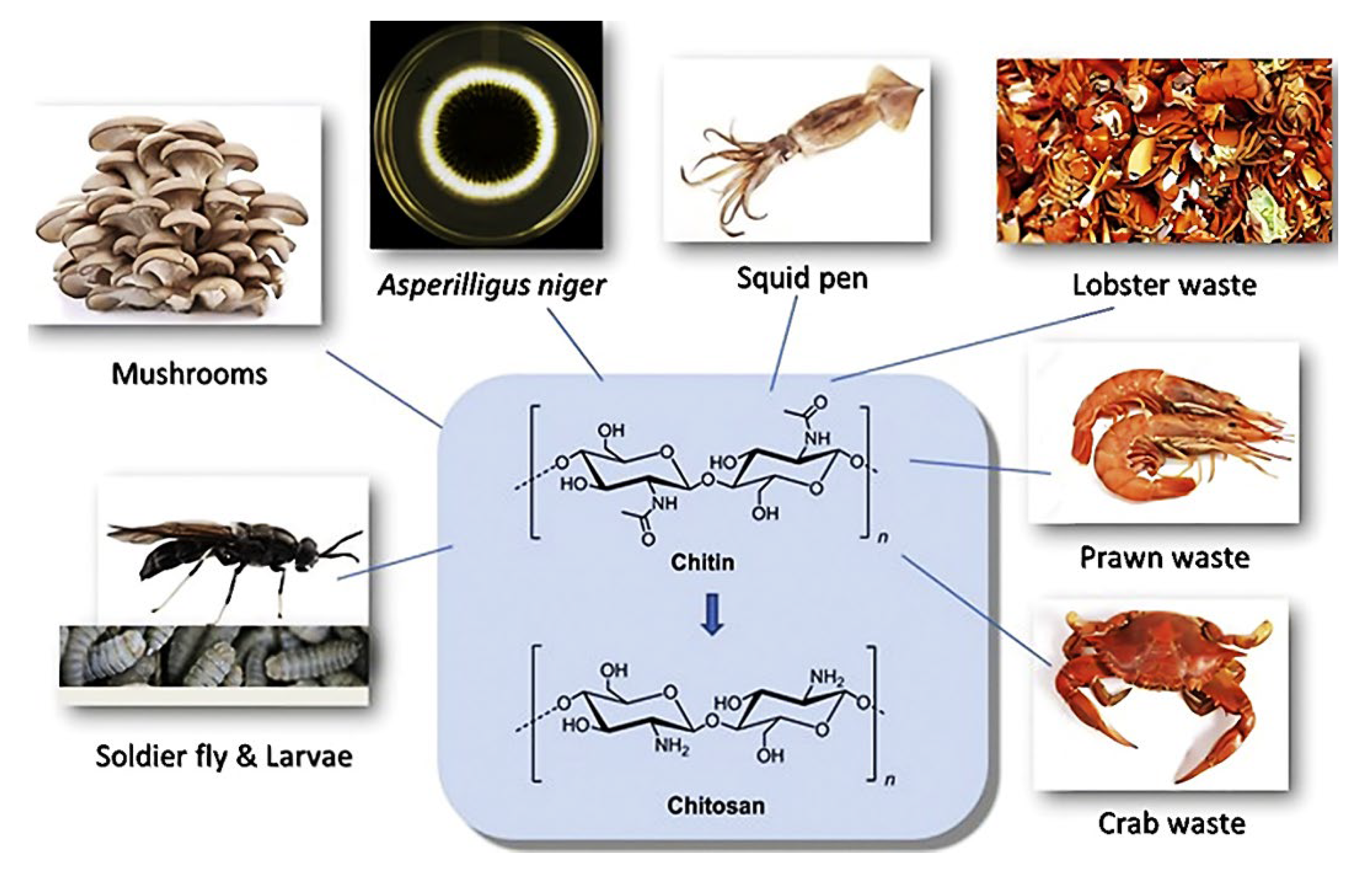
2.4. Chitosan and Chitin
3. Types of Cellulose
3.1. Plant Cellulose
3.2. Bacterial Cellulose
3.3. Comparison between Plant Cellulose and Bacterial Cellulose
3.4. Other Cellulose Types
4. Photocatalyst Nanomaterials
4.1. Titanium Dioxide (TiO2)
4.2. Zinc Oxide (ZnO)
4.3. Graphitic Carbon Nitride (g-C3N4)
4.4. Graphene
5. Synthesizing Method of TiO2-Based Photocatalyst
5.1. Hydrothermal Synthesis
5.2. Sol-Gel Synthesis
5.3. Chemical Vapor Deposition Synthesis
6. Fabrication and Performance of Cellulose Composite Catalysts
6.1. Metal Doping
6.2. Non-Metal Doping
6.3. Metal–Organic Frameworks (MOFs)
7. Challenges and Future Perspective
8. Conclusions
Author Contributions
Funding
Institutional Review Board Statement
Informed Consent Statement
Data Availability Statement
Acknowledgments
Conflicts of Interest
References
- Shen, Y. A Review on Hydrothermal Carbonization of Biomass and Plastic Wastes to Energy Products. Biomass Bioenergy 2020, 134, 105479. [Google Scholar] [CrossRef]
- Chua, S.Y.; Periasamy, L.A.; Goh, C.M.H.; Tan, Y.H.; Mubarak, N.M.; Kansedo, J.; Khalid, M.; Walvekar, R.; Abdullah, E.C. Biodiesel Synthesis Using Natural Solid Catalyst Derived from Biomass Waste—A Review. J. Ind. Eng. Chem. 2020, 81, 41–60. [Google Scholar] [CrossRef]
- Shanmuga Priya, M.; Divya, P.; Rajalakshmi, R. A Review Status on Characterization and Electrochemical Behaviour of Biomass Derived Carbon Materials for Energy Storage Supercapacitors. Sustain. Chem. Pharm. 2020, 16, 100243. [Google Scholar] [CrossRef]
- Osman, A.I.; Abdelkader, A.; Farrell, C.; Rooney, D.; Morgan, K. Reusing, Recycling and up-Cycling of Biomass: A Review of Practical and Kinetic Modelling Approaches. Fuel Process. Technol. 2019, 192, 179–202. [Google Scholar] [CrossRef]
- Khan, T.A.; Saud, A.S.; Jamari, S.S.; Rahim, M.H.A.; Park, J.W.; Kim, H.J. Hydrothermal Carbonization of Lignocellulosic Biomass for Carbon Rich Material Preparation: A Review. Biomass Bioenergy 2019, 130, 105384. [Google Scholar] [CrossRef]
- Phromphithak, S.; Onsree, T.; Tippayawong, N. Machine Learning Prediction of Cellulose-Rich Materials from Biomass Pretreatment with Ionic Liquid Solvents. Bioresour. Technol. 2021, 323, 124642. [Google Scholar] [CrossRef] [PubMed]
- Pennells, J.; Cruickshank, A.; Chaléat, C.; Godwin, I.D.; Martin, D.J. Sorghum as a Novel Biomass for the Sustainable Production of Cellulose Nanofibers. Ind. Crops Prod. 2021, 171, 113917. [Google Scholar] [CrossRef]
- Chairungsri, W.; Subkomkaew, A.; Kijjanapanich, P.; Chimupala, Y. Direct Dye Wastewater Photocatalysis Using Immobilized Titanium Dioxide on Fixed Substrate. Chemosphere 2022, 286, 131762. [Google Scholar] [CrossRef] [PubMed]
- Zhang, X.; Wang, J.; Dong, X.X.; Lv, Y.K. Functionalized Metal-Organic Frameworks for Photocatalytic Degradation of Organic Pollutants in Environment. Chemosphere 2020, 242, 125144. [Google Scholar] [CrossRef]
- Pandey, B.; Prajapati, Y.K.; Sheth, P.N. Recent Progress in Thermochemical Techniques to Produce Hydrogen Gas from Biomass: A State of the Art Review. Int. J. Hydrogen Energy 2019, 44, 25384–25415. [Google Scholar] [CrossRef]
- Nunes, L.J.R.; Causer, T.P.; Ciolkosz, D. Biomass for Energy: A Review on Supply Chain Management Models. Renew. Sustain. Energy Rev. 2020, 120, 109658. [Google Scholar] [CrossRef]
- Olivares-Marín, M.; Fernández, J.A.; Lázaro, M.J.; Fernández-González, C.; Macías-García, A.; Gómez-Serrano, V.; Stoeckli, F.; Centeno, T.A. Cherry Stones as Precursor of Activated Carbons for Supercapacitors. Mater. Chem. Phys. 2009, 114, 323–327. [Google Scholar] [CrossRef] [Green Version]
- Chandra, R.; Takeuchi, H.; Hasegawa, T. Methane Production from Lignocellulosic Agricultural Crop Wastes: A Review in Context to Second Generation of Biofuel Production. Renew. Sustain. Energy Rev. 2012, 16, 1462–1476. [Google Scholar] [CrossRef]
- Li, T.; Takkellapati, S. The Current and Emerging Sources of Technical Lignins and Their Applications. Biofuels Bioprod. Biorefining 2018, 12, 756–787. [Google Scholar] [CrossRef] [PubMed]
- Hameed, S.; Sharma, A.; Pareek, V.; Wu, H.; Yu, Y. A Review on Biomass Pyrolysis Models: Kinetic, Network and Mechanistic Models. Biomass Bioenergy 2019, 123, 104–122. [Google Scholar] [CrossRef]
- Kumar, V.; Yadav, S.K.; Kumar, J.; Ahluwalia, V. A Critical Review on Current Strategies and Trends Employed for Removal of Inhibitors and Toxic Materials Generated during Biomass Pretreatment. Bioresour. Technol. 2020, 299, 122633. [Google Scholar] [CrossRef] [PubMed]
- Ren, J.; Liu, Y.L.; Zhao, X.Y.; Cao, J.P. Biomass Thermochemical Conversion: A Review on Tar Elimination from Biomass Catalytic Gasification. J. Energy Inst. 2020, 93, 1083–1098. [Google Scholar] [CrossRef]
- Food and Agricultural Organization of the United Nations (FAO). Overview: Major trends and issues. In FAO Yearbook of Fishery and Aquaculture Statistics 2017; Food and Agricultural Organization of the United Nations (FAO): Rome, Italy, 2019; pp. 1–108. ISBN 978-92-5-131669-6. [Google Scholar]
- Hamed, I.; Özogul, F.; Regenstein, J.M. Industrial Applications of Crustacean By-Products (Chitin, Chitosan, and Chitooligosaccharides): A Review. Trends Food Sci. Technol. 2016, 48, 40–50. [Google Scholar] [CrossRef]
- Zhang, J.; Xia, W.; Liu, P.; Cheng, Q.; Tahirou, T.; Gu, W.; Li, B. Chitosan Modification and Pharmaceutical/Biomedical Applications. Mar. Drugs 2010, 8, 1962–1987. [Google Scholar] [CrossRef] [PubMed] [Green Version]
- Bakshi, P.S.; Selvakumar, D.; Kadirvelu, K.; Kumar, N.S. Chitosan as an Environment Friendly Biomaterial—A Review on Recent Modifications and Applications. Int. J. Biol. Macromol. 2020, 150, 1072–1083. [Google Scholar] [CrossRef]
- Xiong, X.; Yu, I.K.M.; Cao, L.; Tsang, D.C.W.; Zhang, S.; Ok, Y.S. A Review of Biochar-Based Catalysts for Chemical Synthesis, Biofuel Production, and Pollution Control. Bioresour. Technol. 2017, 246, 254–270. [Google Scholar] [CrossRef] [PubMed]
- Abdullah, S.H.Y.S.; Hanapi, N.H.M.; Azid, A.; Umar, R.; Juahir, H.; Khatoon, H.; Endut, A. A Review of Biomass-Derived Heterogeneous Catalyst for a Sustainable Biodiesel Production. Renew. Sustain. Energy Rev. 2017, 70, 1040–1051. [Google Scholar] [CrossRef]
- Liu, J.; Jiang, J.; Meng, Y.; Aihemaiti, A.; Xu, Y.; Xiang, H.; Gao, Y.; Chen, X. Preparation, Environmental Application and Prospect of Biochar-Supported Metal Nanoparticles: A Review. J. Hazard. Mater. 2020, 388, 122026. [Google Scholar] [CrossRef]
- Tan, X.; Liu, Y.; Zeng, G.; Wang, X.; Hu, X.; Gu, Y.; Yang, Z. Application of Biochar for the Removal of Pollutants from Aqueous Solutions. Chemosphere 2015, 125, 70–85. [Google Scholar] [CrossRef] [PubMed]
- Ahmad, M.; Rajapaksha, A.U.; Lim, J.E.; Zhang, M.; Bolan, N.; Mohan, D.; Vithanage, M.; Lee, S.S.; Ok, Y.S. Biochar as a Sorbent for Contaminant Management in Soil and Water: A Review. Chemosphere 2014, 99, 19–33. [Google Scholar] [CrossRef]
- Qian, K.; Kumar, A.; Zhang, H.; Bellmer, D.; Huhnke, R. Recent Advances in Utilization of Biochar. Renew. Sustain. Energy Rev. 2015, 42, 1055–1064. [Google Scholar] [CrossRef]
- Nor, N.M.; Lau, L.C.; Lee, K.T.; Mohamed, A.R. Synthesis of Activated Carbon from Lignocellulosic Biomass and Its Applications in Air Pollution Control—A Review. J. Environ. Chem. Eng. 2013, 1, 658–666. [Google Scholar] [CrossRef]
- González-García, P. Activated Carbon from Lignocellulosics Precursors: A Review of the Synthesis Methods, Characterization Techniques and Applications. Renew. Sustain. Energy Rev. 2018, 82, 1393–1414. [Google Scholar] [CrossRef]
- Saleem, J.; Bin Shahid, U.; Hijab, M.; Mackey, H.; McKay, G. Production and Applications of Activated Carbons as Adsorbents from Olive Stones. Biomass Convers. Biorefinery 2019, 9, 775–802. [Google Scholar] [CrossRef] [Green Version]
- Azari, A.; Nabizadeh, R.; Nasseri, S.; Mahvi, A.H.; Mesdaghinia, A.R. Comprehensive Systematic Review and Meta-Analysis of Dyes Adsorption by Carbon-Based Adsorbent Materials: Classification and Analysis of Last Decade Studies. Chemosphere 2020, 250, 126238. [Google Scholar] [CrossRef]
- Demirbas, A. Agricultural Based Activated Carbons for the Removal of Dyes from Aqueous Solutions: A Review. J. Hazard. Mater. 2009, 167, 1–9. [Google Scholar] [CrossRef]
- Nayak, A.; Bhushan, B.; Gupta, V.; Sharma, P. Chemically Activated Carbon from Lignocellulosic Wastes for Heavy Metal Wastewater Remediation: Effect of Activation Conditions. J. Colloid Interface Sci. 2017, 493, 228–240. [Google Scholar] [CrossRef]
- Shrestha, D.; Rajbhandari, A. The Effects of Different Activating Agents on the Physical and Electrochemical Properties of Activated Carbon Electrodes Fabricated from Wood-Dust of Shorea robusta. Heliyon 2021, 7, e07917. [Google Scholar] [CrossRef]
- Gao, Y.; Yue, Q.; Gao, B.; Li, A. Insight into Activated Carbon from Different Kinds of Chemical Activating Agents: A Review. Sci. Total Environ. 2020, 746, 141094. [Google Scholar] [CrossRef] [PubMed]
- Zhang, Y.; Song, X.; Xu, Y.; Shen, H.; Kong, X.; Xu, H. Utilization of Wheat Bran for Producing Activated Carbon with High Specific Surface Area via NaOH Activation Using Industrial Furnace. J. Clean. Prod. 2019, 210, 366–375. [Google Scholar] [CrossRef]
- Xiao, W.; Garba, Z.N.; Sun, S.; Lawan, I.; Wang, L.; Lin, M.; Yuan, Z. Preparation and Evaluation of an Effective Activated Carbon from White Sugar for the Adsorption of Rhodamine B Dye. J. Clean. Prod. 2020, 253, 119989. [Google Scholar] [CrossRef]
- Wickramaarachchi, W.A.M.K.P.; Minakshi, M.; Gao, X.; Dabare, R.; Wong, K.W. Hierarchical Porous Carbon from Mango Seed Husk for Electro-Chemical Energy Storage. Chem. Eng. J. Adv. 2021, 8, 100158. [Google Scholar] [CrossRef]
- Wickramaarachchi, K.; Minakshi, M.; Aravindh, S.A.; Dabare, R.; Gao, X.; Jiang, Z.T.; Wong, K.W. Repurposing N-Doped Grape Marc for the Fabrication of Supercapacitors with Theoretical and Machine Learning Models. Nanomaterials 2022, 12, 1847. [Google Scholar] [CrossRef]
- Arun, S.; Kiran, K.U.V.; Kumar, S.M.; Karnan, M.; Sathish, M.; Mayavan, S. Effect of Orange Peel Derived Activated Carbon as a Negative Additive for Lead-Acid Battery under High Rate Discharge Condition. J. Energy Storage 2021, 34, 102225. [Google Scholar] [CrossRef]
- Dou, Y.; Liu, X.; Wang, X.; Yu, K.; Liang, C. Jute Fiber Based Micro-Mesoporous Carbon: A Biomass Derived Anode Material with High-Performance for Lithium-Ion Batteries. Mater. Sci. Eng. B Solid-State Mater. Adv. Technol. 2021, 265, 115015. [Google Scholar] [CrossRef]
- Farooq, A.; Patoary, M.K.; Zhang, M.; Mussana, H.; Li, M.; Naeem, M.A.; Mushtaq, M.; Farooq, A.; Liu, L. Cellulose from Sources to Nanocellulose and an Overview of Synthesis and Properties of Nanocellulose/Zinc Oxide Nanocomposite Materials. Int. J. Biol. Macromol. 2020, 154, 1050–1073. [Google Scholar] [CrossRef]
- Moon, R.J.; Martini, A.; Nairn, J.; Simonsen, J.; Youngblood, J. Cellulose Nanomaterials Review: Structure, Properties and Nanocomposites. Chem. Soc. Rev. 2011, 40, 3941–3994. [Google Scholar] [CrossRef] [PubMed]
- Gopi, S.; Balakrishnan, P.; Chandradhara, D.; Poovathankandy, D.; Thomas, S. General Scenarios of Cellulose and Its Use in the Biomedical Field. Mater. Today Chem. 2019, 13, 59–78. [Google Scholar] [CrossRef]
- Azizi Samir, M.A.S.; Alloin, F.; Dufresne, A. Review of Recent Research into Cellulosic Whiskers, Their Properties and Their Application in Nanocomposite Field. Biomacromolecules 2005, 6, 612–626. [Google Scholar] [CrossRef] [PubMed]
- Habibi, Y.; Lucia, L.A.; Rojas, O.J. Cellulose Nanocrystals: Chemistry, Self-Assembly, and Applications. Chem. Rev. 2010, 110, 3479–3500. [Google Scholar] [CrossRef] [PubMed]
- John, M.J.; Thomas, S. Biofibres and Biocomposites. Carbohydr. Polym. 2008, 71, 343–364. [Google Scholar] [CrossRef]
- Nsor-Atindana, J.; Chen, M.; Goff, H.D.; Zhong, F.; Sharif, H.R.; Li, Y. Functionality and Nutritional Aspects of Microcrystalline Cellulose in Food. Carbohydr. Polym. 2017, 172, 159–174. [Google Scholar] [CrossRef] [PubMed]
- De Souza Lima, M.M.; Borsali, R. Rodlike Cellulose Microcrystals: Structure, Properties, and Applications. Macromol. Rapid Commun. 2004, 25, 771–787. [Google Scholar] [CrossRef]
- Rieland, J.M.; Love, B.J. Ionic Liquids: A Milestone on the Pathway to Greener Recycling of Cellulose from Biomass. Resour. Conserv. Recycl. 2020, 155, 104678. [Google Scholar] [CrossRef]
- Zaman, A.; Huang, F.; Jiang, M.; Wei, W.; Zhou, Z. Preparation, Properties, and Applications of Natural Cellulosic Aerogels: A Review. Energy Built Environ. 2020, 1, 60–76. [Google Scholar] [CrossRef]
- Li, Y.; Lin, M.; Davenport, J.W. Ab Initio Studies of Cellulose I: Crystal Structure, Intermolecular Forces, and Interactions with Water. J. Phys. Chem. C 2011, 115, 11533–11539. [Google Scholar] [CrossRef]
- Ng, H.M.; Sin, L.T.; Tee, T.T.; Bee, S.T.; Hui, D.; Low, C.Y.; Rahmat, A.R. Extraction of Cellulose Nanocrystals from Plant Sources for Application as Reinforcing Agent in Polymers. Compos. Part B Eng. 2015, 75, 176–200. [Google Scholar] [CrossRef]
- Kumar, R.; Sharma, R.K.; Singh, A.P. Cellulose Based Grafted Biosorbents—Journey from Lignocellulose Biomass to Toxic Metal Ions Sorption Applications—A Review. J. Mol. Liq. 2017, 232, 62–93. [Google Scholar] [CrossRef]
- Brinchi, L.; Cotana, F.; Fortunati, E.; Kenny, J.M. Production of Nanocrystalline Cellulose from Lignocellulosic Biomass: Technology and Applications. Carbohydr. Polym. 2013, 94, 154–169. [Google Scholar] [CrossRef]
- Driemeier, C. Nanostructure of lignocellulose and its importance for biomass conversion into chemicals and biofuels. In Advances of Basic Science for Second Generation Bioethanol from Sugarcane; Buckeridge, M.S., De Souza, A.P., Eds.; Springer International Publishing: Cham, Switzerland, 2017; pp. 21–38. ISBN 978-3-319-49824-9. [Google Scholar]
- Jones, D.; Ormondroyd, G.O.; Curling, S.F.; Popescu, C.-M.; Popescu, M.-C. Chemical compositions of natural fibres. In Advanced High Strength Natural Fibre Composites in Construction; Fan, M., Fu, F., Eds.; Elsevier: Amsterdam, The Netherlands, 2017; pp. 23–58. ISBN 9780081004302. [Google Scholar]
- Siqueira, G.; Bras, J.; Dufresne, A. Cellulosic Bionanocomposites: A Review of Preparation, Properties and Applications. Polymers 2010, 2, 728–765. [Google Scholar] [CrossRef] [Green Version]
- Illum, L.; Jabbal-Gill, I.; Hinchcliffe, M.; Fisher, A.N.; Davis, S.S. Chitosan as a Novel Nasal Delivery System for Vaccines. Adv. Drug Deliv. Rev. 2001, 51, 81–96. [Google Scholar] [CrossRef]
- Wei, S.; Ching, Y.C.; Chuah, C.H. Synthesis of Chitosan Aerogels as Promising Carriers for Drug Delivery: A Review. Carbohydr. Polym. 2020, 231, 115744. [Google Scholar] [CrossRef] [PubMed]
- Sampath, U.G.T.M.; Ching, Y.C.; Chuah, C.H.; Singh, R.; Lin, P.C. Preparation and Characterization of Nanocellulose Reinforced Semi-Interpenetrating Polymer Network of Chitosan Hydrogel. Cellulose 2017, 24, 2215–2228. [Google Scholar] [CrossRef]
- Elgadir, M.A.; Uddin, M.S.; Ferdosh, S.; Adam, A.; Chowdhury, A.J.K.; Sarker, M.Z.I. Impact of Chitosan Composites and Chitosan Nanoparticle Composites on Various Drug Delivery Systems: A Review. J. Food Drug Anal. 2015, 23, 619–629. [Google Scholar] [CrossRef] [Green Version]
- Arvanitoyannis, I.S.; Nakayama, A.; Aiba, S. ichi Chitosan and Gelatin Based Edible Films: State Diagrams, Mechanical and Permeation Properties. Carbohydr. Polym. 1998, 37, 371–382. [Google Scholar] [CrossRef]
- Schmitz, C.; Auza, L.G.; Koberidze, D.; Rasche, S.; Fischer, R.; Bortesi, L. Conversion of Chitin to Defined Chitosan Oligomers: Current Status and Future Prospects. Mar. Drugs 2019, 17, 452. [Google Scholar] [CrossRef] [PubMed] [Green Version]
- Andrady, A.L.; Xu, P. Elastic Behavior of Chitosan Films. J. Polym. Sci. Part B Polym. Phys. 1997, 35, 517–521. [Google Scholar] [CrossRef]
- Jardine, A.; Sayed, S. Challenges in the Valorisation of Chitinous Biomass within the Biorefinery Concept. Curr. Opin. Green Sustain. Chem. 2016, 2, 34–39. [Google Scholar] [CrossRef]
- Chaudhary, S.; Kumar, S.; Kumar, V.; Sharma, R. Chitosan Nanoemulsions as Advanced Edible Coatings for Fruits and Vegetables: Composition, Fabrication and Developments in Last Decade. Int. J. Biol. Macromol. 2020, 152, 154–170. [Google Scholar] [CrossRef] [PubMed]
- Younes, I.; Rinaudo, M. Chitin and Chitosan Preparation from Marine Sources. Structure, Properties and Applications. Mar. Drugs 2015, 13, 1133–1174. [Google Scholar] [CrossRef] [PubMed] [Green Version]
- Sánchez-Machado, D.I.; López-Cervantes, J.; Correa-Murrieta, M.A.; Sánchez-Duarte, R.G.; Cruz-Flores, P.; de la Mora-López, G.S. Chitosan. In Nonvitamin and Nonmineral Nutritional Supplements; Elsevier Inc.: Amsterdam, The Netherlands, 2019; pp. 485–493. ISBN 9780128124918. [Google Scholar]
- Xu, Y.; Bajaj, M.; Schneider, R.; Grage, S.L.; Ulrich, A.S.; Winter, J.; Gallert, C. Transformation of the Matrix Structure of Shrimp Shells during Bacterial Deproteination and Demineralization. Microb. Cell Fact. 2013, 12, 90. [Google Scholar] [CrossRef] [PubMed] [Green Version]
- Huang, G.; Liu, Y.; Chen, L. Chitosan and Its Derivatives as Vehicles for Drug Delivery. Drug Deliv. 2017, 24, 108–113. [Google Scholar] [CrossRef]
- Ramkumar, R.; Minakshi, M. Fabrication of Ultrathin CoMoO4 Nanosheets Modified with Chitosan and Their Improved Performance in Energy Storage Device. Dalton Trans. 2015, 44, 6158–6168. [Google Scholar] [CrossRef] [PubMed]
- Ramkumar, R.; Minakshi, M. A Biopolymer Gel-Decorated Cobalt Molybdate Nanowafer: Effective Graft Polymer Cross-Linked with an Organic Acid for Better Energy Storage. New J. Chem. 2016, 40, 2863–2877. [Google Scholar] [CrossRef]
- Ioelovich, M. Cellulose as a Nanostructured Polymer: A Short Review. BioResources 2008, 3, 1403–1418. [Google Scholar] [CrossRef]
- Abdul Khalil, H.P.S.; Davoudpour, Y.; Islam, M.N.; Mustapha, A.; Sudesh, K.; Dungani, R.; Jawaid, M. Production and Modification of Nanofibrillated Cellulose Using Various Mechanical Processes: A Review. Carbohydr. Polym. 2014, 99, 649–665. [Google Scholar] [CrossRef] [PubMed]
- Foresti, M.L.; Vázquez, A.; Boury, B. Applications of Bacterial Cellulose as Precursor of Carbon and Composites with Metal Oxide, Metal Sulfide and Metal Nanoparticles: A Review of Recent Advances. Carbohydr. Polym. 2017, 157, 447–467. [Google Scholar] [CrossRef]
- Klemm, D.; Heublein, B.; Fink, H.P.; Bohn, A. Cellulose: Fascinating Biopolymer and Sustainable Raw Material. Angew. Chem. Int. Ed. 2005, 44, 3358–3393. [Google Scholar] [CrossRef] [PubMed]
- Carpenter, A.W.; de Lannoy, C.F.; Wiesner, M.R. Cellulose Nanomaterials in Water Treatment Technologies. Environ. Sci. Technol. 2015, 49, 5277–5287. [Google Scholar] [CrossRef] [PubMed] [Green Version]
- Kumar, R.; Strezov, V.; Weldekidan, H.; He, J.; Singh, S.; Kan, T.; Dastjerdi, B. Lignocellulose Biomass Pyrolysis for Bio-Oil Production: A Review of Biomass Pre-Treatment Methods for Production of Drop-in Fuels. Renew. Sustain. Energy Rev. 2020, 123, 109763. [Google Scholar] [CrossRef]
- Jin, Z.; Katsumata, K.S.; Lam, T.B.T.; Iiyama, K. Covalent Linkages between Cellulose and Lignin in Cell Walls of Coniferous and Nonconiferous Woods. Biopolymers 2006, 83, 103–110. [Google Scholar] [CrossRef] [PubMed]
- Bhat, A.H.; Khan, I.; Usmani, M.A.; Umapathi, R.; Al-Kindy, S.M.Z. Cellulose an Ageless Renewable Green Nanomaterial for Medical Applications: An Overview of Ionic Liquids in Extraction, Separation and Dissolution of Cellulose. Int. J. Biol. Macromol. 2019, 129, 750–777. [Google Scholar] [CrossRef]
- Peng, B.; Yao, Z.; Wang, X.; Crombeen, M.; Sweeney, D.G.; Tam, K.C. Cellulose-Based Materials in Wastewater Treatment of Petroleum Industry. Green Energy Environ. 2020, 5, 37–49. [Google Scholar] [CrossRef]
- Sharma, A.; Thakur, M.; Bhattacharya, M.; Mandal, T.; Goswami, S. Commercial Application of Cellulose Nano-Composites—A Review. Biotechnol. Rep. 2019, 21, e00316. [Google Scholar] [CrossRef] [PubMed]
- Garba, Z.N.; Lawan, I.; Zhou, W.; Zhang, M.; Wang, L.; Yuan, Z. Microcrystalline Cellulose (MCC) Based Materials as Emerging Adsorbents for the Removal of Dyes and Heavy Metals—A Review. Sci. Total Environ. 2020, 717, 135070. [Google Scholar] [CrossRef]
- Pachuau, L.; Dutta, R.S.; Hauzel, L.; Devi, T.B.; Deka, D. Evaluation of Novel Microcrystalline Cellulose from Ensete glaucum (Roxb.) Cheesman Biomass as Sustainable Drug Delivery Biomaterial. Carbohydr. Polym. 2019, 206, 336–343. [Google Scholar] [CrossRef]
- Ren, H.; Shen, J.; Pei, J.; Wang, Z.; Peng, Z.; Fu, S.; Zheng, Y. Characteristic Microcrystalline Cellulose Extracted by Combined Acid and Enzyme Hydrolysis of Sweet Sorghum. Cellulose 2019, 26, 8367–8381. [Google Scholar] [CrossRef]
- Baruah, J.; Deka, R.C.; Kalita, E. Greener Production of Microcrystalline Cellulose (MCC) from Saccharum spontaneum (Kans Grass): Statistical Optimization. Int. J. Biol. Macromol. 2020, 154, 672–682. [Google Scholar] [CrossRef] [PubMed]
- Abu-Thabit, N.Y.; Judeh, A.A.; Hakeem, A.S.; Ul-Hamid, A.; Umar, Y.; Ahmad, A. Isolation and Characterization of Microcrystalline Cellulose from Date Seeds (Phoenix dactylifera L.). Int. J. Biol. Macromol. 2020, 155, 730–739. [Google Scholar] [CrossRef] [PubMed]
- Fouad, H.; Kian, L.K.; Jawaid, M.; Alotaibi, M.D.; Alothman, O.Y.; Hashem, M. Characterization of Microcrystalline Cellulose Isolated from Conocarpus Fiber. Polymers 2020, 12, 2926. [Google Scholar] [CrossRef]
- Islam, M.S.; Kao, N.; Bhattacharya, S.N.; Gupta, R.; Choi, H.J. Potential Aspect of Rice Husk Biomass in Australia for Nanocrystalline Cellulose Production. Chin. J. Chem. Eng. 2018, 26, 465–476. [Google Scholar] [CrossRef]
- Hastuti, N.; Kanomata, K.; Kitaoka, T. Hydrochloric Acid Hydrolysis of Pulps from Oil Palm Empty Fruit Bunches to Produce Cellulose Nanocrystals. J. Polym. Environ. 2018, 26, 3698–3709. [Google Scholar] [CrossRef]
- Trilokesh, C.; Uppuluri, K.B. Isolation and Characterization of Cellulose Nanocrystals from Jackfruit Peel. Sci. Rep. 2019, 9, 16709. [Google Scholar] [CrossRef]
- Kian, L.K.; Saba, N.; Jawaid, M.; Alothman, O.Y.; Fouad, H. Properties and Characteristics of Nanocrystalline Cellulose Isolated from Olive Fiber. Carbohydr. Polym. 2020, 241, 116423. [Google Scholar] [CrossRef]
- Nang An, V.; Chi Nhan, H.T.; Tap, T.D.; Van, T.T.T.; Van Viet, P.; Van Hieu, L. Extraction of High Crystalline Nanocellulose from Biorenewable Sources of Vietnamese Agricultural Wastes. J. Polym. Environ. 2020, 28, 1465–1474. [Google Scholar] [CrossRef]
- Mishra, S.; Kharkar, P.S.; Pethe, A.M. Biomass and Waste Materials as Potential Sources of Nanocrystalline Cellulose: Comparative Review of Preparation Methods (2016–Till Date). Carbohydr. Polym. 2019, 207, 418–427. [Google Scholar] [CrossRef]
- Sarkar, N.; Ghosh, S.K.; Bannerjee, S.; Aikat, K. Bioethanol Production from Agricultural Wastes: An Overview. Renew. Energy 2012, 37, 19–27. [Google Scholar] [CrossRef]
- Sharma, N.; Bhardwaj, N.K.; Singh, R.B.P. Environmental Issues of Pulp Bleaching and Prospects of Peracetic Acid Pulp Bleaching: A Review. J. Clean. Prod. 2020, 256, 120338. [Google Scholar] [CrossRef]
- Dilamian, M.; Noroozi, B. A Combined Homogenization-High Intensity Ultrasonication Process for Individualizaion of Cellulose Micro-Nano Fibers from Rice Straw. Cellulose 2019, 26, 5831–5849. [Google Scholar] [CrossRef]
- Kumneadklang, S.; O-Thong, S.; Larpkiattaworn, S. Characterization of Cellulose Fiber Isolated from Oil Palm Frond Biomass. In Materials Today: Proceedings of the First Materials Research Society of Thailand International Conference, Chiang Mai, Thailand, 31 October–3 November 2017; Elsevier Ltd.: Amsterdam, The Netherlands, 2019; Volume 17, pp. 1995–2001. [Google Scholar]
- Candido, R.G.; Gonçalves, A.R. Evaluation of Two Different Applications for Cellulose Isolated from Sugarcane Bagasse in a Biorefinery Concept. Ind. Crops Prod. 2019, 142, 111616. [Google Scholar] [CrossRef]
- Qasim, U.; Ali, Z.; Nazir, M.S.; Ul Hassan, S.; Rafiq, S.; Jamil, F.; Al-Muhtaseb, A.H.; Ali, M.; Khan Niazi, M.B.; Ahmad, N.M.; et al. Isolation of Cellulose from Wheat Straw Using Alkaline Hydrogen Peroxide and Acidified Sodium Chlorite Treatments: Comparison of Yield and Properties. Adv. Polym. Technol. 2020, 2020, 9765950. [Google Scholar] [CrossRef] [Green Version]
- Syafri, E.; Jamaluddin; Sari, N.H.; Mahardika, M.; Amanda, P.; Ilyas, R.A. Isolation and Characterization of Cellulose Nanofibers from Agave gigantea by Chemical-Mechanical Treatment. Int. J. Biol. Macromol. 2022, 200, 25–33. [Google Scholar] [CrossRef] [PubMed]
- Pasma, S.A.; Daik, R.; Maskat, M.Y.; Hassan, O. Application of Box-Behnken Design in Optimization of Glucose Production from Oil Palm Empty Fruit Bunch Cellulose. Int. J. Polym. Sci. 2013, 2013, 104502. [Google Scholar] [CrossRef] [Green Version]
- Brown, A.J. XLIII.—On an Acetic Ferment Which Forms Cellulose. J. Chem. Soc. Trans. 1886, 49, 432–439. [Google Scholar] [CrossRef] [Green Version]
- Iguchi, M.; Yamanaka, S.; Budhiono, A. Bacterial Cellulose—A Masterpiece of Nature’s Arts. J. Mater. Sci. 2000, 35, 261–270. [Google Scholar] [CrossRef]
- Gatenholm, P.; Klemm, D. Bacterial Nanocellulose as a Renewable Material for Biomedical Applications. MRS Bull. 2010, 35, 208–213. [Google Scholar] [CrossRef]
- Jonas, R.; Farah, L.F. Production and Application of Microbial Cellulose. Polym. Degrad. Stab. 1998, 59, 101–106. [Google Scholar] [CrossRef]
- Wang, J.; Tavakoli, J.; Tang, Y. Bacterial Cellulose Production, Properties and Applications with Different Culture Methods—A Review. Carbohydr. Polym. 2019, 219, 63–76. [Google Scholar] [CrossRef] [PubMed] [Green Version]
- Lin, S.P.; Loira Calvar, I.; Catchmark, J.M.; Liu, J.R.; Demirci, A.; Cheng, K.C. Biosynthesis, Production and Applications of Bacterial Cellulose. Cellulose 2013, 20, 2191–2219. [Google Scholar] [CrossRef]
- Mohammadkazemi, F.; Azin, M.; Ashori, A. Production of Bacterial Cellulose Using Different Carbon Sources and Culture Media. Carbohydr. Polym. 2015, 117, 518–523. [Google Scholar] [CrossRef] [PubMed]
- Klemm, D.; Schumann, D.; Udhardt, U.; Marsch, S. Bacterial Synthesized Cellulose—Artificial Blood Vessels for Microsurgery. Prog. Polym. Sci. 2001, 26, 1561–1603. [Google Scholar] [CrossRef]
- Ross, P.; Mayer, R.; Benziman, M. Cellulose Biosynthesis and Function in Bacteria. Microbiol. Mol. Biol. Rev. 1991, 55, 35–58. [Google Scholar] [CrossRef]
- Qiu, K.; Netravali, A.N. A Review of Fabrication and Applications of Bacterial Cellulose Based Nanocomposites. Polym. Rev. 2014, 54, 598–626. [Google Scholar] [CrossRef]
- Islam, M.U.; Ullah, M.W.; Khan, S.; Shah, N.; Park, J.K. Strategies for Cost-Effective and Enhanced Production of Bacterial Cellulose. Int. J. Biol. Macromol. 2017, 102, 1166–1173. [Google Scholar] [CrossRef]
- Pang, M.; Huang, Y.; Meng, F.; Zhuang, Y.; Liu, H.; Du, M.; Ma, Q.; Wang, Q.; Chen, Z.; Chen, L.; et al. Application of Bacterial Cellulose in Skin and Bone Tissue Engineering. Eur. Polym. J. 2020, 122, 109365. [Google Scholar] [CrossRef]
- Chawla, P.R.; Bajaj, I.B.; Survase, S.A.; Singhal, R.S. Microbial Cellulose: Fermentative Production and Applications. Food Technol. Biotechnol. 2009, 47, 107–124. [Google Scholar]
- Ul-Islam, M.; Khan, S.; Ullah, M.W.; Park, J.K. Bacterial Cellulose Composites: Synthetic Strategies and Multiple Applications in Bio-Medical and Electro-Conductive Fields. Biotechnol. J. 2015, 10, 1847–1861. [Google Scholar] [CrossRef]
- Hu, Y.; Catchmark, J.M. Formation and Characterization of Spherelike Bacterial Cellulose Particles Produced by Acetobacter xylinum JCM 9730 Strain. Biomacromolecules 2010, 11, 1727–1734. [Google Scholar] [CrossRef] [PubMed]
- Choi, S.M.; Shin, E.J. The Nanofication and Functionalization of Bacterial Cellulose and Its Applications. Nanomaterials 2020, 10, 406. [Google Scholar] [CrossRef] [Green Version]
- Chao, Y.; Sugano, Y.; Kouda, T.; Yoshinaga, F.; Shoda, M. Production of Bacterial Cellulose by Acetobacter xylinum with an Air-Lift Reactor. Biotechnol. Tech. 1997, 11, 829–832. [Google Scholar] [CrossRef]
- Wang, B.; Lv, X.; Chen, S.; Li, Z.; Sun, X.; Feng, C.; Wang, H.; Xu, Y. In Vitro Biodegradability of Bacterial Cellulose by Cellulase in Simulated Body Fluid and Compatibility in Vivo. Cellulose 2016, 23, 3187–3198. [Google Scholar] [CrossRef]
- Römling, U.; Galperin, M.Y. Bacterial Cellulose Biosynthesis: Diversity of Operons, Subunits, Products, and Functions. Trends Microbiol. 2015, 23, 545–557. [Google Scholar] [CrossRef] [PubMed] [Green Version]
- Jonoobi, M.; Oladi, R.; Davoudpour, Y.; Oksman, K.; Dufresne, A.; Hamzeh, Y.; Davoodi, R. Different Preparation Methods and Properties of Nanostructured Cellulose from Various Natural Resources and Residues: A Review. Cellulose 2015, 22, 935–969. [Google Scholar] [CrossRef]
- Torres, F.G.; Arroyo, J.J.; Troncoso, O.P. Bacterial Cellulose Nanocomposites: An All-Nano Type of Material. Mater. Sci. Eng. C 2019, 98, 1277–1293. [Google Scholar] [CrossRef]
- Khoo, C.G.; Dasan, Y.K.; Lam, M.K.; Lee, K.T. Algae Biorefinery: Review on a Broad Spectrum of Downstream Processes and Products. Bioresour. Technol. 2019, 292, 121964. [Google Scholar] [CrossRef]
- Sirajunnisa, A.R.; Surendhiran, D. Algae—A Quintessential and Positive Resource of Bioethanol Production: A Comprehensive Review. Renew. Sustain. Energy Rev. 2016, 66, 248–267. [Google Scholar] [CrossRef]
- Zheng, L.X.; Chen, X.Q.; Cheong, K.L. Current Trends in Marine Algae Polysaccharides: The Digestive Tract, Microbial Catabolism, and Prebiotic Potential. Int. J. Biol. Macromol. 2020, 151, 344–354. [Google Scholar] [CrossRef] [PubMed]
- Rangabhashiyam, S.; Balasubramanian, P. Characteristics, Performances, Equilibrium and Kinetic Modeling Aspects of Heavy Metal Removal Using Algae. Bioresour. Technol. Rep. 2019, 5, 261–279. [Google Scholar] [CrossRef]
- Cheng, S.Y.; Show, P.L.; Lau, B.F.; Chang, J.S.; Ling, T.C. New Prospects for Modified Algae in Heavy Metal Adsorption. Trends Biotechnol. 2019, 37, 1255–1268. [Google Scholar] [CrossRef] [PubMed]
- Tsekos, I. The Sites of Cellulose Synthesis in Algae: Diversity and Evolution of Cellulose-synthesizing Enzyme Complexes. J. Phycol. 1999, 35, 635–655. [Google Scholar] [CrossRef]
- Itoh, T. Cellulose Synthesizing Complexes in Some Giant Marine Algae. J. Cell Sci. 1990, 95, 309–319. [Google Scholar] [CrossRef]
- Rånby, B.; Rambo, C.R. Natural cellulose fibers and membranes: Biosynthesis. In Reference Module in Materials Science and Materials Engineering; Elsevier: Amsterdam, The Netherlands, 2017; pp. 1–7. ISBN 9780128035818. [Google Scholar]
- Sampath Udeni Gunathilake, T.M.; Ching, Y.C.; Chuah, C.H.; Rahman, N.A.; Liou, N.S. Recent Advances in Celluloses and Their Hybrids for Stimuli-Responsive Drug Delivery. Int. J. Biol. Macromol. 2020, 158, 670–688. [Google Scholar] [CrossRef] [PubMed]
- Mu, R.; Hong, X.; Ni, Y.; Li, Y.; Pang, J.; Wang, Q.; Xiao, J.; Zheng, Y. Recent Trends and Applications of Cellulose Nanocrystals in Food Industry. Trends Food Sci. Technol. 2019, 93, 136–144. [Google Scholar] [CrossRef]
- Syrpas, M.; Venskutonis, P.R. Algae for the production of bio-based products. In Biobased Products and Industries; Galanakis, C.M., Ed.; Elsevier Inc.: Amsterdam, The Netherlands, 2020; pp. 203–243. ISBN 9780128184936. [Google Scholar]
- Zhao, Y.; Li, J. Excellent Chemical and Material Cellulose from Tunicates: Diversity in Cellulose Production Yield and Chemical and Morphological Structures from Different Tunicate Species. Cellulose 2014, 21, 3427–3441. [Google Scholar] [CrossRef]
- Hirose, E.; Kimura, S.; Itoh, T.; Nishikawa, J. Tunic Morphology and Cellulosic Components of Pyrosomas, Doliolids, and Salps (Thaliacea, Urochordata). Biol. Bull. 1999, 196, 113–120. [Google Scholar] [CrossRef] [PubMed]
- Bauermeister, A.; Branco, P.C.; Furtado, L.C.; Jimenez, P.C.; Costa-Lotufo, L.V.; da Cruz Lotufo, T.M. Tunicates: A Model Organism to Investigate the Effects of Associated-Microbiota on the Production of Pharmaceuticals. Drug Discov. Today Dis. Model. 2018, 28, 13–20. [Google Scholar] [CrossRef]
- Hirose, E. Ascidian Tunic Cells: Morphology and Functional Diversity of Free Cells outside the Epidermis. Invertebr. Biol. 2009, 128, 83–96. [Google Scholar] [CrossRef]
- Sasakura, Y.; Nakashima, K.; Awazu, S.; Matsuoka, T.; Nakayama, A.; Azuma, J.I.; Satoh, N. Transposon-Mediated Insertional Mutagenesis Revealed the Functions of Animal Cellulose Synthase in the Ascidian Ciona intestinalis. In Proceedings of the National Academy of Sciences, Washington, DC, USA, 1 March 2005; Volume 102, pp. 15134–15139. [Google Scholar]
- Calvino, C.; Macke, N.; Kato, R.; Rowan, S.J. Development, Processing and Applications of Bio-Sourced Cellulose Nanocrystal Composites. Prog. Polym. Sci. 2020, 103, 101221. [Google Scholar] [CrossRef]
- Zhao, Y.; Zhang, Y.; Lindström, M.E.; Li, J. Tunicate Cellulose Nanocrystals: Preparation, Neat Films and Nanocomposite Films with Glucomannans. Carbohydr. Polym. 2015, 117, 286–296. [Google Scholar] [CrossRef] [PubMed]
- Ruiz, M.M.; Cavaillé, J.Y.; Dufresne, A.; Graillat, C.; Gérard, J. New Waterborne Epoxy Coatings Based on Cellulose Nanofillers. Macromol. Symp. 2001, 169, 211–222. [Google Scholar] [CrossRef]
- Grishkewich, N.; Mohammed, N.; Tang, J.; Tam, K.C. Recent Advances in the Application of Cellulose Nanocrystals. Curr. Opin. Colloid Interface Sci. 2017, 29, 32–45. [Google Scholar] [CrossRef]
- Wang, Z.; Li, N.; Zong, L.; Zhang, J. Recent Advances in Vacuum Assisted Self-Assembly of Cellulose Nanocrystals. Curr. Opin. Solid State Mater. Sci. 2019, 23, 142–148. [Google Scholar] [CrossRef]
- Sharma, S.; Dutta, V.; Singh, P.; Raizada, P.; Rahmani-Sani, A.; Hosseini-Bandegharaei, A.; Thakur, V.K. Carbon Quantum Dot Supported Semiconductor Photocatalysts for Efficient Degradation of Organic Pollutants in Water: A Review. J. Clean. Prod. 2019, 228, 755–769. [Google Scholar] [CrossRef]
- Al-Mamun, M.R.; Kader, S.; Islam, M.S.; Khan, M.Z.H. Photocatalytic Activity Improvement and Application of UV-TiO2 Photocatalysis in Textile Wastewater Treatment: A Review. J. Environ. Chem. Eng. 2019, 7, 103248. [Google Scholar] [CrossRef]
- Onkani, S.P.; Diagboya, P.N.; Mtunzi, F.M.; Klink, M.J.; Olu-Owolabi, B.I.; Pakade, V. Comparative Study of the Photocatalytic Degradation of 2–Chlorophenol under UV Irradiation Using Pristine and Ag-Doped Species of TiO2, ZnO and ZnS Photocatalysts. J. Environ. Manag. 2020, 260, 110145. [Google Scholar] [CrossRef]
- Fujishima, A.; Kohayakawa, K.; Honda, K. Hydrogen Production under Sunlight with an Electrochemical Photocell. J. Electrochem. Soc. 1975, 122, 1487–1489. [Google Scholar] [CrossRef]
- Chen, D.; Cheng, Y.; Zhou, N.; Chen, P.; Wang, Y.; Li, K.; Huo, S.; Cheng, P.; Peng, P.; Zhang, R.; et al. Photocatalytic Degradation of Organic Pollutants Using TiO2-Based Photocatalysts: A Review. J. Clean. Prod. 2020, 268, 121725. [Google Scholar] [CrossRef]
- Pelaez, M.; Nolan, N.T.; Pillai, S.C.; Seery, M.K.; Falaras, P.; Kontos, A.G.; Dunlop, P.S.M.; Hamilton, J.W.J.; Byrne, J.A.; O’Shea, K.; et al. A Review on the Visible Light Active Titanium Dioxide Photocatalysts for Environmental Applications. Appl. Catal. B Environ. 2012, 125, 331–349. [Google Scholar] [CrossRef] [Green Version]
- Khaki, M.R.D.; Shafeeyan, M.S.; Raman, A.A.A.; Daud, W.M.A.W. Application of Doped Photocatalysts for Organic Pollutant Degradation—A Review. J. Environ. Manag. 2017, 198, 78–94. [Google Scholar] [CrossRef] [PubMed]
- Kamat, P.V. TiO2 Nanostructures: Recent Physical Chemistry Advances. J. Phys. Chem. C 2012, 116, 11849–11851. [Google Scholar] [CrossRef]
- Ibhadon, A.O.; Fitzpatrick, P. Heterogeneous Photocatalysis: Recent Advances and Applications. Catalysts 2013, 3, 189–218. [Google Scholar] [CrossRef] [Green Version]
- Acharya, R.; Parida, K. A Review on TiO2/g-C3N4 Visible-Light-Responsive Photocatalysts for Sustainable Energy Generation and Environmental Remediation. J. Environ. Chem. Eng. 2020, 8, 103896. [Google Scholar] [CrossRef]
- Kusiak-Nejman, E.; Morawski, A.W. TiO2/Graphene-Based Nanocomposites for Water Treatment: A Brief Overview of Charge Carrier Transfer, Antimicrobial and Photocatalytic Performance. Appl. Catal. B Environ. 2019, 253, 179–186. [Google Scholar] [CrossRef]
- Xu, F. Review of Analytical Studies on TiO2 Nanoparticles and Particle Aggregation, Coagulation, Flocculation, Sedimentation, Stabilization. Chemosphere 2018, 212, 662–677. [Google Scholar] [CrossRef]
- Ola, O.; Maroto-Valer, M.M. Review of Material Design and Reactor Engineering on TiO2 Photocatalysis for CO2 Reduction. J. Photochem. Photobiol. C Photochem. Rev. 2015, 24, 16–42. [Google Scholar] [CrossRef] [Green Version]
- Mun, S.J.; Park, S.J. Graphitic Carbon Nitride Materials for Photocatalytic Hydrogen Production via Water Splitting: A Short Review. Catalysts 2019, 9, 805. [Google Scholar] [CrossRef]
- Reyes-Coronado, D.; Rodríguez-Gattorno, G.; Espinosa-Pesqueira, M.E.; Cab, C.; de Coss, R.; Oskam, G. Phase-Pure TiO2 Nanoparticles: Anatase, Brookite and Rutile. Nanotechnology 2008, 19, 145605. [Google Scholar] [CrossRef] [PubMed]
- Chen, X.; Mao, S.S. Titanium Dioxide Nanomaterials: Synthesis, Properties, Modifications and Applications. Chem. Rev. 2007, 107, 2891–2959. [Google Scholar] [CrossRef] [PubMed]
- Di Mo, S.; Ching, W.Y. Electronic and Optical Properties of Three Phases of Titanium Dioxide: Rutile, Anatase, and Brookite. Phys. Rev. B 1995, 51, 13023–13032. [Google Scholar] [CrossRef]
- Yamakata, A.; Vequizo, J.J.M. Curious Behaviors of Photogenerated Electrons and Holes at the Defects on Anatase, Rutile, and Brookite TiO2 Powders: A Review. J. Photochem. Photobiol. C Photochem. Rev. 2019, 40, 234–243. [Google Scholar] [CrossRef]
- Zhang, J.; Zhou, P.; Liu, J.; Yu, J. New Understanding of the Difference of Photocatalytic Activity among Anatase, Rutile and Brookite TiO2. Phys. Chem. Chem. Phys. 2014, 16, 20382–20386. [Google Scholar] [CrossRef]
- Rani, M.; Shanker, U. Green synthesis of TiO2 and its photocatalytic activity. In Handbook of Smart Photocatalytic Materials: Fundamentals, Fabrications and Water Resources Applications; Hussain, C.M., Mishra, A.K., Eds.; Elsevier: Amsterdam, The Netherlands, 2020; pp. 11–61. ISBN 9780128190517. [Google Scholar]
- Haggerty, J.E.S.; Schelhas, L.T.; Kitchaev, D.A.; Mangum, J.S.; Garten, L.M.; Sun, W.; Stone, K.H.; Perkins, J.D.; Toney, M.F.; Ceder, G.; et al. High-Fraction Brookite Films from Amorphous Precursors. Sci. Rep. 2017, 7, 15232. [Google Scholar] [CrossRef] [Green Version]
- Zhou, T.; Chen, S.; Li, L.; Wang, J.; Zhang, Y.; Li, J.; Bai, J.; Xia, L.; Xu, Q.; Rahim, M.; et al. Carbon Quantum Dots Modified Anatase/Rutile TiO2 Photoanode with Dramatically Enhanced Photoelectrochemical Performance. Appl. Catal. B Environ. 2020, 269, 118776. [Google Scholar] [CrossRef]
- Di Paola, A.; Bellardita, M.; Palmisano, L. Brookite, the Least Known TiO2 Photocatalyst. Catalysts 2013, 3, 36–73. [Google Scholar] [CrossRef] [Green Version]
- Vequizo, J.J.M.; Matsunaga, H.; Ishiku, T.; Kamimura, S.; Ohno, T.; Yamakata, A. Trapping-Induced Enhancement of Photocatalytic Activity on Brookite TiO2 Powders: Comparison with Anatase and Rutile TiO2 Powders. ACS Catal. 2017, 7, 2644–2651. [Google Scholar] [CrossRef]
- Pirhashemi, M.; Habibi-Yangjeh, A.; Rahim Pouran, S. Review on the Criteria Anticipated for the Fabrication of Highly Efficient ZnO-Based Visible-Light-Driven Photocatalysts. J. Ind. Eng. Chem. 2018, 62, 1–25. [Google Scholar] [CrossRef]
- Raizada, P.; Sudhaik, A.; Singh, P. Photocatalytic Water Decontamination Using Graphene and ZnO Coupled Photocatalysts: A Review. Mater. Sci. Energy Technol. 2019, 2, 509–525. [Google Scholar] [CrossRef]
- Janotti, A.; Van De Walle, C.G. Fundamentals of Zinc Oxide as a Semiconductor. Rep. Prog. Phys. 2009, 72, 126501. [Google Scholar] [CrossRef] [Green Version]
- Zhu, D.; Zhou, Q. Action and Mechanism of Semiconductor Photocatalysis on Degradation of Organic Pollutants in Water Treatment: A Review. Environ. Nanotechnol. Monit. Manag. 2019, 12, 100255. [Google Scholar] [CrossRef]
- Kumar, S.G.; Rao, K.S.R.K. Zinc Oxide Based Photocatalysis: Tailoring Surface-Bulk Structure and Related Interfacial Charge Carrier Dynamics for Better Environmental Applications. RSC Adv. 2015, 5, 3306–3351. [Google Scholar] [CrossRef]
- Tekin, D.; Kiziltas, H.; Ungan, H. Kinetic Evaluation of ZnO/TiO2 Thin Film Photocatalyst in Photocatalytic Degradation of Orange G. J. Mol. Liq. 2020, 306, 112905. [Google Scholar] [CrossRef]
- Hou, J.; Wu, Y.; Li, X.; Wei, B.; Li, S.; Wang, X. Toxic Effects of Different Types of Zinc Oxide Nanoparticles on Algae, Plants, Invertebrates, Vertebrates and Microorganisms. Chemosphere 2018, 193, 852–860. [Google Scholar] [CrossRef]
- Özgür, Ü.; Alivov, Y.I.; Liu, C.; Teke, A.; Reshchikov, M.A.; Doğan, S.; Avrutin, V.; Cho, S.-J.; Morkoç, H. A Comprehensive Review of ZnO Materials and Devices. J. Appl. Phys. 2005, 98, 041301. [Google Scholar] [CrossRef] [Green Version]
- Lee, K.M.; Lai, C.W.; Ngai, K.S.; Juan, J.C. Recent Developments of Zinc Oxide Based Photocatalyst in Water Treatment Technology: A Review. Water Res. 2016, 88, 428–448. [Google Scholar] [CrossRef]
- Naseri, A.; Samadi, M.; Pourjavadi, A.; Moshfegh, A.Z.; Ramakrishna, S. Graphitic Carbon Nitride (g-C3N4)-Based Photocatalysts for Solar Hydrogen Generation: Recent Advances and Future Development Directions. J. Mater. Chem. A 2017, 5, 23406–23433. [Google Scholar] [CrossRef]
- Lam, S.M.; Sin, J.C.; Mohamed, A.R. A Review on Photocatalytic Application of G-C3N4/Semiconductor (CNS) Nanocomposites towards the Erasure of Dyeing Wastewater. Mater. Sci. Semicond. Process. 2016, 47, 62–84. [Google Scholar] [CrossRef]
- Wang, X.; Maeda, K.; Thomas, A.; Takanabe, K.; Xin, G.; Carlsson, J.M.; Domen, K.; Antonietti, M. A Metal-Free Polymeric Photocatalyst for Hydrogen Production from Water under Visible Light. Nat. Mater. 2009, 8, 76–80. [Google Scholar] [CrossRef] [PubMed]
- Mishra, A.; Mehta, A.; Basu, S.; Shetti, N.P.; Reddy, K.R.; Aminabhavi, T.M. Graphitic Carbon Nitride (g–C3N4)–Based Metal-Free Photocatalysts for Water Splitting: A Review. Carbon N. Y. 2019, 149, 693–721. [Google Scholar] [CrossRef]
- Wang, Y.; Wang, X.; Antonietti, M. Polymeric Graphitic Carbon Nitride as a Heterogeneous Organocatalyst: From Photochemistry to Multipurpose Catalysis to Sustainable Chemistry. Angew. Chem. Int. Ed. 2012, 51, 68–89. [Google Scholar] [CrossRef]
- Zhang, S.; Gu, P.; Ma, R.; Luo, C.; Wen, T.; Zhao, G.; Cheng, W.; Wang, X. Recent Developments in Fabrication and Structure Regulation of Visible-Light-Driven g-C3N4-Based Photocatalysts towards Water Purification: A Critical Review. Catal. Today 2019, 335, 65–77. [Google Scholar] [CrossRef]
- Mamba, G.; Mishra, A.K. Graphitic Carbon Nitride (g-C3N4) Nanocomposites: A New and Exciting Generation of Visible Light Driven Photocatalysts for Environmental Pollution Remediation. Appl. Catal. B Environ. 2016, 198, 347–377. [Google Scholar] [CrossRef]
- Zheng, Y.; Lin, L.; Wang, B.; Wang, X. Graphitic Carbon Nitride Polymers toward Sustainable Photoredox Catalysis. Angew. Chem. Int. Ed. 2015, 54, 12868–12884. [Google Scholar] [CrossRef]
- Huang, D.; Li, Z.; Zeng, G.; Zhou, C.; Xue, W.; Gong, X.; Yan, X.; Chen, S.; Wang, W.; Cheng, M. Megamerger in Photocatalytic Field: 2D g-C3N4 Nanosheets Serve as Support of 0D Nanomaterials for Improving Photocatalytic Performance. Appl. Catal. B Environ. 2019, 240, 153–173. [Google Scholar] [CrossRef]
- Prasad, C.; Tang, H.; Liu, Q.; Bahadur, I.; Karlapudi, S.; Jiang, Y. A Latest Overview on Photocatalytic Application of G-C3N4 Based Nanostructured Materials for Hydrogen Production. Int. J. Hydrogen Energy 2020, 45, 337–379. [Google Scholar] [CrossRef]
- Xu, Y.; Kraft, M.; Xu, R. Metal-Free Carbonaceous Electrocatalysts and Photocatalysts for Water Splitting. Chem. Soc. Rev. 2016, 45, 3039–3052. [Google Scholar] [CrossRef] [PubMed]
- Dong, G.; Zhang, Y.; Pan, Q.; Qiu, J. A Fantastic Graphitic Carbon Nitride (g-C3N4) Material: Electronic Structure, Photocatalytic and Photoelectronic Properties. J. Photochem. Photobiol. C Photochem. Rev. 2014, 20, 33–50. [Google Scholar] [CrossRef]
- Li, X.; Yu, J.; Wageh, S.; Al-Ghamdi, A.A.; Xie, J. Graphene in Photocatalysis: A Review. Small 2016, 12, 6640–6696. [Google Scholar] [CrossRef]
- Prasad, C.; Liu, Q.; Tang, H.; Yuvaraja, G.; Long, J.; Rammohan, A.; Zyryanov, G.V. An Overview of Graphene Oxide Supported Semiconductors Based Photocatalysts: Properties, Synthesis and Photocatalytic Applications. J. Mol. Liq. 2020, 297, 111826. [Google Scholar] [CrossRef]
- Kahng, S.; Yoo, H.; Kim, J.H. Recent Advances in Earth-Abundant Photocatalyst Materials for Solar H2 Production. Adv. Powder Technol. 2020, 31, 11–28. [Google Scholar] [CrossRef]
- Bai, H.; Li, C.; Shi, G. Functional Composite Materials Based on Chemically Converted Graphene. Adv. Mater. 2011, 23, 1089–1115. [Google Scholar] [CrossRef] [PubMed]
- Rosman, N.N.; Mohamad Yunus, R.; Jeffery Minggu, L.; Arifin, K.; Salehmin, M.N.I.; Mohamed, M.A.; Kassim, M.B. Photocatalytic Properties of Two-Dimensional Graphene and Layered Transition-Metal Dichalcogenides Based Photocatalyst for Photoelectrochemical Hydrogen Generation: An Overview. Int. J. Hydrogen Energy 2018, 43, 18925–18945. [Google Scholar] [CrossRef]
- Bano, Z.; Mazari, S.A.; Saeed, R.M.Y.; Majeed, M.A.; Xia, M.; Memon, A.Q.; Abro, R.; Wang, F. Water Decontamination by 3D Graphene Based Materials: A Review. J. Water Process Eng. 2020, 36, 101404. [Google Scholar] [CrossRef]
- Nikokavoura, A.; Trapalis, C. Graphene and G-C3N4 Based Photocatalysts for NOx Removal: A Review. Appl. Surf. Sci. 2018, 430, 18–52. [Google Scholar] [CrossRef]
- Pottathara, Y.B.; Tiyyagura, H.R.; Ahmad, Z.; Sadasivuni, K.K. Graphene Based Aerogels: Fundamentals and Applications as Supercapacitors. J. Energy Storage 2020, 30, 101549. [Google Scholar] [CrossRef]
- Ji, X.; Xu, Y.; Zhang, W.; Cui, L.; Liu, J. Review of Functionalization, Structure and Properties of Graphene/Polymer Composite Fibers. Compos. Part A Appl. Sci. Manuf. 2016, 87, 29–45. [Google Scholar] [CrossRef]
- Xiang, Q.; Yu, J.; Jaroniec, M. Graphene-Based Semiconductor Photocatalysts. Chem. Soc. Rev. 2012, 41, 782–796. [Google Scholar] [CrossRef] [PubMed]
- Zhao, S.; Zhao, Z.; Yang, Z.; Ke, L.L.; Kitipornchai, S.; Yang, J. Functionally Graded Graphene Reinforced Composite Structures: A Review. Eng. Struct. 2020, 210, 110339. [Google Scholar] [CrossRef]
- Sonia, F.J.; Aslam, M.; Mukhopadhyay, A. Understanding the Processing-Structure-Performance Relationship of Graphene and Its Variants as Anode Material for Li-Ion Batteries: A Critical Review. Carbon N. Y. 2020, 156, 130–165. [Google Scholar] [CrossRef]
- Tarelho, J.P.G.; Soares dos Santos, M.P.; Ferreira, J.A.F.; Ramos, A.; Kopyl, S.; Kim, S.O.; Hong, S.; Kholkin, A. Graphene-Based Materials and Structures for Energy Harvesting with Fluids—A Review. Mater. Today 2018, 21, 1019–1041. [Google Scholar] [CrossRef]
- Mehmood, A.; Mubarak, N.M.; Khalid, M.; Walvekar, R.; Abdullah, E.C.; Siddiqui, M.T.H.; Baloch, H.A.; Nizamuddin, S.; Mazari, S. Graphene Based Nanomaterials for Strain Sensor Application—A Review. J. Environ. Chem. Eng. 2020, 8, 103743. [Google Scholar] [CrossRef]
- Verma, R.; Gangwar, J.; Srivastava, A.K. Multiphase TiO2 Nanostructures: A Review of Efficient Synthesis, Growth Mechanism, Probing Capabilities, and Applications in Bio-Safety and Health. RSC Adv. 2017, 7, 44199–44224. [Google Scholar] [CrossRef] [Green Version]
- Mamaghani, A.H.; Haghighat, F.; Lee, C.S. Systematic Variation of Preparation Time, Temperature, and Pressure in Hydrothermal Synthesis of Macro-/Mesoporous TiO2 for Photocatalytic Air Treatment. J. Photochem. Photobiol. A Chem. 2019, 378, 156–170. [Google Scholar] [CrossRef]
- Sun, Y.; Gao, Y.; Zeng, J.; Guo, J.; Wang, H. Enhancing Visible-Light Photocatalytic Activity of Ag-TiO2 Nanowire Composites by One-Step Hydrothermal Process. Mater. Lett. 2020, 279, 128506. [Google Scholar] [CrossRef]
- Santhi, K.; Navaneethan, M.; Harish, S.; Ponnusamy, S.; Muthamizhchelvan, C. Synthesis and Characterization of TiO2 Nanorods by Hydrothermal Method with Different PH Conditions and Their Photocatalytic Activity. Appl. Surf. Sci. 2020, 500, 144058. [Google Scholar] [CrossRef]
- Wang, H.; Qi, F.; Chen, X.; Guo, H.; Cui, W. Enhanced Photoelectrocatalytic Degradation by TiO2 Nano-Arrays Decorated with Two-Dimensional Ultra-Thin P3HT Nanosheets. Mater. Lett. 2021, 302, 130432. [Google Scholar] [CrossRef]
- Chen, M.; Sun, T.; Zhao, W.; Yang, X.; Chang, W.; Qian, X.; Yang, Q.; Chen, Z. In Situ Growth of Metallic 1T-MoS2 on TiO2 Nanotubes with Improved Photocatalytic Performance. ACS Omega 2021, 6, 12787–12793. [Google Scholar] [CrossRef]
- Zhang, Q.; Wang, Y.; Zhu, X.; Liu, X.; Li, H. 1T and 2H Mixed Phase MoS2 Nanobelts Coupled with Ti3+ Self-Doped TiO2 Nanosheets for Enhanced Photocatalytic Degradation of RhB under Visible Light. Appl. Surf. Sci. 2021, 556, 149768. [Google Scholar] [CrossRef]
- Estrada-Flores, S.; Martínez-Luévanos, A.; Perez-Berumen, C.M.; García-Cerda, L.A.; Flores-Guia, T.E. Relationship between Morphology, Porosity, and the Photocatalytic Activity of TiO2 Obtained by Sol–Gel Method Assisted with Ionic and Nonionic Surfactants. Bol. Soc. Esp. Ceram. Vidr. 2020, 59, 209–218. [Google Scholar] [CrossRef]
- Abraham, C.; Devi, L.G. One-Pot Facile Sol-Gel Synthesis of W, N, C and S Doped TiO2 and Its Application in the Photocatalytic Degradation of Thymol under the Solar Light Irradiation: Reaction Kinetics and Degradation Mechanism. J. Phys. Chem. Solids 2020, 141, 109350. [Google Scholar] [CrossRef]
- Abbad, S.; Guergouri, K.; Gazaout, S.; Djebabra, S.; Zertal, A.; Barille, R.; Zaabat, M. Effect of Silver Doping on the Photocatalytic Activity of TiO2 Nanopowders Synthesized by the Sol-Gel Route. J. Environ. Chem. Eng. 2020, 8, 103718. [Google Scholar] [CrossRef]
- Pragathiswaran, C.; Smitha, C.; Abbubakkar, B.M.; Govindhan, P.; Krishnan, N.A. Synthesis and Characterization of TiO2/ZnO-Ag Nanocomposite for Photocatalytic Degradation of Dyes and Anti-Microbial Activity. In Materials Today: Proceedings of the International Conference on Advances in Materials Research, Tamil Nadu, India, 27–28 May 2021; Elsevier Ltd.: Amsterdam, The Netherlands, 2021; Volume 45, pp. 3357–3364. [Google Scholar]
- Jesus, M.A.M.L.; Ferreira, A.M.; Lima, L.F.S.; Batista, G.F.; Mambrini, R.V.; Mohallem, N.D.S. Micro-Mesoporous TiO2/SiO2 Nanocomposites: Sol-Gel Synthesis, Characterization, and Enhanced Photodegradation of Quinoline. Ceram. Int. 2021, 47, 23844–23850. [Google Scholar] [CrossRef]
- De Filpo, G.; Pantuso, E.; Armentano, K.; Formoso, P.; Di Profio, G.; Poerio, T.; Fontananova, E.; Meringolo, C.; Mashin, A.I.; Nicoletta, F.P. Chemical Vapor Deposition of Photocatalyst Nanoparticles on PVDF Membranes for Advanced Oxidation Processes. Membranes 2018, 8, 35. [Google Scholar] [CrossRef] [Green Version]
- Jeong, S.; Lee, H.; Park, H.; Jeon, K.J.; Park, Y.K.; Jung, S.C. Rapid Photocatalytic Degradation of Nitrobenzene under the Simultaneous Illumination of UV and Microwave Radiation Fields with a TiO2 Ball Catalyst. Catal. Today 2018, 307, 65–72. [Google Scholar] [CrossRef]
- Park, Y.K.; Ha, H.H.; Yu, Y.H.; Kim, B.J.; Bang, H.J.; Lee, H.; Jung, S.C. The Photocatalytic Destruction of Cimetidine Using Microwave-Assisted TiO2 Photocatalysts Hybrid System. J. Hazard. Mater. 2020, 391, 122568. [Google Scholar] [CrossRef] [PubMed]
- Hadjltaief, H.B.; Ben Zina, M.; Galvez, M.E.; Da Costa, P. Photocatalytic Degradation of Methyl Green Dye in Aqueous Solution over Natural Clay-Supported ZnO-TiO2 Catalysts. J. Photochem. Photobiol. A Chem. 2016, 315, 25–33. [Google Scholar] [CrossRef] [Green Version]
- Nada, A.A.; Nasr, M.; Viter, R.; Miele, P.; Roualdes, S.; Bechelany, M. Mesoporous ZnFe2O4@TiO2 Nanofibers Prepared by Electrospinning Coupled to PECVD as Highly Performing Photocatalytic Materials. J. Phys. Chem. C 2017, 121, 24669–24677. [Google Scholar] [CrossRef]
- Bento, R.T.; Correa, O.V.; Pillis, M.F. On the Surface Chemistry and the Reuse of Sulfur-Doped TiO2 Films as Photocatalysts. Mater. Chem. Phys. 2021, 261, 124231. [Google Scholar] [CrossRef]
- Mamaghani, A.H.; Haghighat, F.; Lee, C.S. Hydrothermal/Solvothermal Synthesis and Treatment of TiO2 for Photocatalytic Degradation of Air Pollutants: Preparation, Characterization, Properties, and Performance. Chemosphere 2019, 219, 804–825. [Google Scholar] [CrossRef] [PubMed]
- Gomathi Thanga Keerthana, B.; Solaiyammal, T.; Muniyappan, S.; Murugakoothan, P. Hydrothermal Synthesis and Characterization of TiO2 Nanostructures Prepared Using Different Solvents. Mater. Lett. 2018, 220, 20–23. [Google Scholar] [CrossRef]
- Ismael, M. A Review and Recent Advances in Solar-to-Hydrogen Energy Conversion Based on Photocatalytic Water Splitting over Doped-TiO2 Nanoparticles. Sol. Energy 2020, 211, 522–546. [Google Scholar] [CrossRef]
- Baral, A.; Das, D.P.; Minakshi, M.; Ghosh, M.K.; Padhi, D.K. Probing Environmental Remediation of RhB Organic Dye Using α-MnO2 under Visible- Light Irradiation: Structural, Photocatalytic and Mineralization Studies. ChemistrySelect 2016, 1, 4277–4285. [Google Scholar] [CrossRef]
- Yu, J.; Lei, J.; Wang, L.; Zhang, J.; Liu, Y. TiO2 Inverse Opal Photonic Crystals: Synthesis, Modification, and Applications—A Review. J. Alloy. Compd. 2018, 769, 740–757. [Google Scholar] [CrossRef]
- Gomes, J.; Lincho, J.; Domingues, E.; Quinta-Ferreira, R.M.; Martins, R.C. N-TiO2 Photocatalysts: A Review of Their Characteristics and Capacity for Emerging Contaminants Removal. Water 2019, 11, 373. [Google Scholar] [CrossRef] [Green Version]
- Akpan, U.G.; Hameed, B.H. The Advancements in Sol-Gel Method of Doped-TiO2 Photocatalysts. Appl. Catal. A Gen. 2010, 375, 1–11. [Google Scholar] [CrossRef]
- Singh, R.; Dutta, S. A Review on H2 Production through Photocatalytic Reactions Using TiO2/TiO2-Assisted Catalysts. Fuel 2018, 220, 607–620. [Google Scholar] [CrossRef]
- MacWan, D.P.; Dave, P.N.; Chaturvedi, S. A Review on Nano-TiO2 Sol-Gel Type Syntheses and Its Applications. J. Mater. Sci. 2011, 46, 3669–3686. [Google Scholar] [CrossRef]
- Wang, Y.; He, Y.; Lai, Q.; Fan, M. Review of the Progress in Preparing Nano TiO2: An Important Environmental Engineering Material. J. Environ. Sci. 2014, 26, 2139–2177. [Google Scholar] [CrossRef]
- Zhang, Y.; Xiong, X.; Han, Y.; Zhang, X.; Shen, F.; Deng, S.; Xiao, H.; Yang, X.; Yang, G.; Peng, H. Photoelectrocatalytic Degradation of Recalcitrant Organic Pollutants Using TiO2 Film Electrodes: An Overview. Chemosphere 2012, 88, 145–154. [Google Scholar] [CrossRef] [PubMed]
- Shakeel Ahmad, M.; Pandey, A.K.; Abd Rahim, N. Advancements in the Development of TiO2 Photoanodes and Its Fabrication Methods for Dye Sensitized Solar Cell (DSSC) Applications. A Review. Renew. Sustain. Energy Rev. 2017, 77, 89–108. [Google Scholar] [CrossRef]
- Varshney, G.; Kanel, S.R.; Kempisty, D.M.; Varshney, V.; Agrawal, A.; Sahle-Demessie, E.; Varma, R.S.; Nadagouda, M.N. Nanoscale TiO2 Films and Their Application in Remediation of Organic Pollutants. Coord. Chem. Rev. 2016, 306, 43–64. [Google Scholar] [CrossRef]
- Do, H.H.; Nguyen, D.L.T.; Nguyen, X.C.; Le, T.H.; Nguyen, T.P.; Trinh, Q.T.; Ahn, S.H.; Vo, D.V.N.; Kim, S.Y.; Van Le, Q. Recent Progress in TiO2-Based Photocatalysts for Hydrogen Evolution Reaction: A Review. Arab. J. Chem. 2020, 13, 3653–3671. [Google Scholar] [CrossRef]
- Patil, S.B.; Basavarajappa, P.S.; Ganganagappa, N.; Jyothi, M.S.; Raghu, A.V.; Reddy, K.R. Recent Advances in Non-Metals-Doped TiO2 Nanostructured Photocatalysts for Visible-Light Driven Hydrogen Production, CO2 Reduction and Air Purification. Int. J. Hydrogen Energy 2019, 44, 13022–13039. [Google Scholar] [CrossRef]
- Dehghani, M.; Nadeem, H.; Raghuwanshi, V.S.; Mahdavi, H.; Banaszak Holl, M.M.; Batchelor, W. ZnO/Cellulose Nanofiber Composites for Sustainable Sunlight-Driven Dye Degradation. ACS Appl. Nano Mater. 2020, 3, 10284–10295. [Google Scholar] [CrossRef]
- Lu, M.; Cui, Y.; Zhao, S.; Fakhri, A. Cr2O3/Cellulose Hybrid Nanocomposites with Unique Properties: Facile Synthesis, Photocatalytic, Bactericidal and Antioxidant Application. J. Photochem. Photobiol. B Biol. 2020, 205, 111842. [Google Scholar] [CrossRef] [PubMed]
- Gan, L.; Geng, A.; Song, C.; Xu, L.; Wang, L.; Fang, X.; Han, S.; Cui, J.; Mei, C. Simultaneous Removal of Rhodamine B and Cr(VI) from Water Using Cellulose Carbon Nanofiber Incorporated with Bismuth Oxybromide: The Effect of Cellulose Pyrolysis Temperature on Photocatalytic Performance. Environ. Res. 2020, 185, 109414. [Google Scholar] [CrossRef] [PubMed]
- Wang, J.; Li, X.; Cheng, Q.; Lv, F.; Chang, C.; Zhang, L. Construction of β-FeOOH@tunicate Cellulose Nanocomposite Hydrogels and Their Highly Efficient Photocatalytic Properties. Carbohydr. Polym. 2020, 229, 115470. [Google Scholar] [CrossRef]
- Yang, L.; Chen, C.; Hu, Y.; Wei, F.; Cui, J.; Zhao, Y.; Xu, X.; Chen, X.; Sun, D. Three-Dimensional Bacterial Cellulose/Polydopamine/TiO2 Nanocomposite Membrane with Enhanced Adsorption and Photocatalytic Degradation for Dyes under Ultraviolet-Visible Irradiation. J. Colloid Interface Sci. 2020, 562, 21–28. [Google Scholar] [CrossRef] [PubMed]
- Du, X.; Wang, Z.; Pan, J.; Gong, W.; Liao, Q.; Liu, L.; Yao, J. High Photocatalytic Activity of Cu@Cu2O/RGO/Cellulose Hybrid Aerogels as Reusable Catalysts with Enhanced Mass and Electron Transfer. React. Funct. Polym. 2019, 138, 79–87. [Google Scholar] [CrossRef]
- Li, H.; Zhang, L.; Lu, H.; Ma, J.; Zhou, X.; Wang, Z.; Yi, C. Macro-/Nanoporous Al-Doped ZnO/Cellulose Composites Based on Tunable Cellulose Fiber Sizes for Enhancing Photocatalytic Properties. Carbohydr. Polym. 2020, 250, 116873. [Google Scholar] [CrossRef]
- Li, Y.; Pan, Y.; Zhang, B.; Liu, R. Adsorption and Photocatalytic Activity of Cu-Doped Cellulose Nanofibers/Nano-Titanium Dioxide for Different Types of Dyes. Water Sci. Technol. 2020, 82, 1665–1675. [Google Scholar] [CrossRef] [PubMed]
- Ahmed, M.K.; Shalan, A.E.; Afifi, M.; El-Desoky, M.M.; Lanceros-Méndez, S. Silver-Doped Cadmium Selenide/Graphene Oxide-Filled Cellulose Acetate Nanocomposites for Photocatalytic Degradation of Malachite Green toward Wastewater Treatment. ACS Omega 2021, 6, 23129–23138. [Google Scholar] [CrossRef]
- Abdullah, H.; Hsu, C.N.; Shuwanto, H.; Gultom, N.S.; Kebede, W.L.; Wu, C.M.; Lai, C.C.; Murakami, R.I.; Hirota, M.; Nakagaito, A.N.; et al. Immobilization of Cross-Linked In-Doped Mo(O,S)2 on Cellulose Nanofiber for Effective Organic-Compound Degradation under Visible Light Illumination. Prog. Nat. Sci. Mater. Int. 2021, 31, 404–413. [Google Scholar] [CrossRef]
- Mohamed, M.A.; Wan Salleh, W.N.; Jaafar, J.; Rosmi, M.S.; Hir, Z.A.M.; Abd Mutalib, M.; Ismail, A.F.; Tanemura, M. Carbon as Amorphous Shell and Interstitial Dopant in Mesoporous Rutile TiO2: Bio-Template Assisted Sol-Gel Synthesis and Photocatalytic Activity. Appl. Surf. Sci. 2017, 393, 46–59. [Google Scholar] [CrossRef]
- Liu, F.; Sun, Y.; Gu, J.; Gao, Q.; Sun, D.; Zhang, X.; Pan, B.; Qian, J. Highly Efficient Photodegradation of Various Organic Pollutants in Water: Rational Structural Design of Photocatalyst via Thiol-Ene Click Reaction. Chem. Eng. J. 2020, 381, 122631. [Google Scholar] [CrossRef]
- Ahn, J.; Pak, S.; Kim, H. Synergetic Effect of Carbon Dot at Cellulose Nanofiber for Sustainable Metal-Free Photocatalyst. Cellulose 2021, 28, 11261–11274. [Google Scholar] [CrossRef]
- Pham, X.N.; Pham, D.T.; Ngo, H.S.; Nguyen, M.B.; Doan, H.V. Characterization and Application of C–TiO2 Doped Cellulose Acetate Nanocomposite Film for Removal of Reactive Red-195. Chem. Eng. Commun. 2021, 208, 304–317. [Google Scholar] [CrossRef]
- Emam, H.E.; Abdelhamid, H.N.; Abdelhameed, R.M. Self-Cleaned Photoluminescent Viscose Fabric Incorporated Lanthanide-Organic Framework (Ln-MOF). Dye Pigments 2018, 159, 491–498. [Google Scholar] [CrossRef]
- Wen, J.; Liu, H.; Zheng, Y.; Wu, Y.; Gao, J. A Novel of PTA/ZIF-8@cellulose Aerogel Composite Materials for Efficient Photocatalytic Degradation of Organic Dyes in Water. Z. Anorg. Allg. Chem. 2020, 646, 444–450. [Google Scholar] [CrossRef]
- Lu, W.; Duan, C.; Liu, C.; Zhang, Y.; Meng, X.; Dai, L.; Wang, W.; Yu, H.; Ni, Y. A Self-Cleaning and Photocatalytic Cellulose-Fiber- Supported “Ag@AgCl@MOF-Cloth’’ Membrane for Complex Wastewater Remediation. Carbohydr. Polym. 2020, 247, 116691. [Google Scholar] [CrossRef] [PubMed]
- Lu, W.; Duan, C.; Zhang, Y.; Gao, K.; Dai, L.; Shen, M.; Wang, W.; Wang, J.; Ni, Y. Cellulose-Based Electrospun Nanofiber Membrane with Core-Sheath Structure and Robust Photocatalytic Activity for Simultaneous and Efficient Oil Emulsions Separation, Dye Degradation and Cr(VI) Reduction. Carbohydr. Polym. 2021, 258, 117676. [Google Scholar] [CrossRef] [PubMed]
- Zhao, Y.; Wang, Y.; Xiao, G.; Su, H. Fabrication of Biomaterial/TiO2 Composite Photocatalysts for the Selective Removal of Trace Environmental Pollutants. Chin. J. Chem. Eng. 2019, 27, 1416–1428. [Google Scholar] [CrossRef]
- Rajagopal, S.; Paramasivam, B.; Muniyasamy, K. Photocatalytic Removal of Cationic and Anionic Dyes in the Textile Wastewater by H2O2 Assisted TiO2 and Micro-Cellulose Composites. Sep. Purif. Technol. 2020, 252, 117444. [Google Scholar] [CrossRef]
- Chen, Y.; Xiang, Z.; Wang, D.; Kang, J.; Qi, H. Effective Photocatalytic Degradation and Physical Adsorption of Methylene Blue Using Cellulose/GO/TiO2 Hydrogels. RSC Adv. 2020, 10, 23936–23943. [Google Scholar] [CrossRef]
- Tavker, N.; Gaur, U.; Sharma, M. Cellulose Supported Bismuth Vanadate Nanocomposite for Effective Removal of Organic Pollutant. J. Environ. Chem. Eng. 2020, 8, 104027. [Google Scholar] [CrossRef]
- Sharma, R.K.; Kumar, R. Functionalized Cellulose with Hydroxyethyl Methacrylate and Glycidyl Methacrylate for Metal Ions and Dye Adsorption Applications. Int. J. Biol. Macromol. 2019, 134, 704–721. [Google Scholar] [CrossRef]
- Sharma, R.K.; Kumar, R.; Singh, A.P. Metal Ions and Organic Dyes Sorption Applications of Cellulose Grafted with Binary Vinyl Monomers. Sep. Purif. Technol. 2019, 209, 684–697. [Google Scholar] [CrossRef]
- Moharrami, P.; Motamedi, E. Application of Cellulose Nanocrystals Prepared from Agricultural Wastes for Synthesis of Starch-Based Hydrogel Nanocomposites: Efficient and Selective Nanoadsorbent for Removal of Cationic Dyes from Water. Bioresour. Technol. 2020, 313, 123661. [Google Scholar] [CrossRef] [PubMed]
- Komal; Gupta, K.; Kumar, V.; Tikoo, K.B.; Kaushik, A.; Singhal, S. Encrustation of Cadmium Sulfide Nanoparticles into the Matrix of Biomass Derived Silanized Cellulose Nanofibers for Adsorptive Detoxification of Pesticide and Textile Waste. Chem. Eng. J. 2020, 385, 123700. [Google Scholar] [CrossRef]
- Iravani Mohammadabadi, S.; Javanbakht, V. Fabrication of Dual Cross-Linked Spherical Treated Waste Biomass/Alginate Adsorbent and Its Potential for Efficient Removal of Lead Ions from Aqueous Solutions. Ind. Crops Prod. 2021, 168, 113575. [Google Scholar] [CrossRef]
- Tahazadeh, S.; Karimi, H.; Mohammadi, T.; Emrooz, H.B.M.; Tofighy, M.A. Fabrication of Biodegradable Cellulose Acetate/MOF-Derived Porous Carbon Nanocomposite Adsorbent for Methylene Blue Removal from Aqueous Solutions. J. Solid State Chem. 2021, 299, 122180. [Google Scholar] [CrossRef]
- Liu, Q.; Yu, H.; Zeng, F.; Li, X.; Sun, J.; Li, C.; Lin, H.; Su, Z. HKUST-1 Modified Ultrastability Cellulose/Chitosan Composite Aerogel for Highly Efficient Removal of Methylene Blue. Carbohydr. Polym. 2021, 255, 117402. [Google Scholar] [CrossRef] [PubMed]
- Zhou, Q.; Chen, J.J.; Jin, B.; Chu, S.; Peng, R. Modification of ZIF-8 on Bacterial Cellulose for an Efficient Selective Capture of U(VI). Cellulose 2021, 28, 5241–5256. [Google Scholar] [CrossRef]
- Abdelhameed, R.M.; Abdel-Gawad, H.; Emam, H.E. Macroporous Cu-MOF@cellulose Acetate Membrane Serviceable in Selective Removal of Dimethoate Pesticide from Wastewater. J. Environ. Chem. Eng. 2021, 9, 105121. [Google Scholar] [CrossRef]
- Bian, W.; Chen, J.; Chen, Y.; Xu, W.; Jia, J. A Novel Waste Paper Cellulose-Based Cu-MOF Hybrid Material Threaded by PSS for Lithium Extraction with High Adsorption Capacity and Selectivity. Cellulose 2021, 28, 3041–3054. [Google Scholar] [CrossRef]
- Modi, S.; Fulekar, M.H. Synthesis and Characterization of Zinc Oxide Nanoparticles and Zinc Oxide/Cellulose Nanocrystals Nanocomposite for Photocatalytic Degradation of Methylene Blue Dye under Solar Light Irradiation. Nanotechnol. Environ. Eng. 2020, 5, 18. [Google Scholar] [CrossRef]
- Anusuyadevi, P.R.; Riazanova, A.V.; Hedenqvist, M.S.; Svagan, A.J. Floating Photocatalysts for Effluent Refinement Based on Stable Pickering Cellulose Foams and Graphitic Carbon Nitride (g-C3N4). ACS Omega 2020, 5, 22411–22419. [Google Scholar] [CrossRef] [PubMed]
- Yoon, Y.H.; Lee, S.Y.; Gwon, J.G.; Cho, H.J.; Wu, Q.; Kim, Y.H.; Lee, W.H. Photocatalytic Performance of Highly Transparent and Mesoporous Molybdenum-Doped Titania Films Fabricated by Templating Cellulose Nanocrystals. Ceram. Int. 2018, 44, 16647–16653. [Google Scholar] [CrossRef]
- Yang, Q.; Zhai, Y.; Li, X.; Li, H. Synthesis of Fe3O4/Pr-BiOCl/Luffa Composites with Enhanced Visible Light Photoactivity for Organic Dyes Degradation. Mater. Res. Bull. 2018, 106, 409–417. [Google Scholar] [CrossRef]
- Yang, J.; Luo, X. Ag-Doped TiO2 Immobilized Cellulose-Derived Carbon Beads: One-Pot Preparation, Photocatalytic Degradation Performance and Mechanism of Ceftriaxone Sodium. Appl. Surf. Sci. 2021, 542, 148724. [Google Scholar] [CrossRef]
- Zhao, J.; Chen, X.; Zhou, Y.; Tian, H.; Guo, Q.; Hu, X. Efficient Removal of Oil Pollutant via Simultaneous Adsorption and Photocatalysis Using La–N–TiO2–Cellulose/SiO2 Difunctional Aerogel Composite. Res. Chem. Intermed. 2020, 46, 1805–1822. [Google Scholar] [CrossRef]
- RanguMagar, A.B.; Chhetri, B.P.; Parameswaran-Thankam, A.; Watanabe, F.; Sinha, A.; Kim, J.W.; Saini, V.; Biris, A.S.; Ghosh, A. Nanocrystalline Cellulose-Derived Doped Carbonaceous Material for Rapid Mineralization of Nitrophenols under Visible Light. ACS Omega 2018, 3, 8111–8121. [Google Scholar] [CrossRef]
- Xiao, H.; Shan, Y.; Zhang, W.; Huang, L.; Chen, L.; Ni, Y.; Boury, B.; Wu, H. C-Nanocoated ZnO by TEMPO-Oxidized Cellulose Templating for Improved Photocatalytic Performance. Carbohydr. Polym. 2020, 235, 115958. [Google Scholar] [CrossRef]
- Zhang, C.; Guo, D.; Shen, T.; Hou, X.; Zhu, M.; Liu, S.; Hu, Q. Titanium Dioxide/Magnetic Metal-Organic Framework Preparation for Organic Pollutants Removal from Water under Visible Light. Colloids Surf. A Physicochem. Eng. Asp. 2020, 589, 124484. [Google Scholar] [CrossRef]
- Abdelhameed, R.M.; El-Shahat, M.; Emam, H.E. Employable Metal (Ag & Pd)@MIL-125-NH2@cellulose Acetate Film for Visible-Light Driven Photocatalysis for Reduction of Nitro-Aromatics. Carbohydr. Polym. 2020, 247, 116695. [Google Scholar] [CrossRef]
- Emam, H.E.; El-Shahat, M.; Abdelhameed, R.M. Observable Removal of Pharmaceutical Residues by Highly Porous Photoactive Cellulose Acetate@MIL-MOF Film. J. Hazard. Mater. 2021, 414, 125509. [Google Scholar] [CrossRef]
- Xiu, Z.; Guo, M.; Zhao, T.; Pan, K.; Xing, Z.; Li, Z.; Zhou, W. Recent Advances in Ti3+ Self-Doped Nanostructured TiO2 Visible Light Photocatalysts for Environmental and Energy Applications. Chem. Eng. J. 2020, 382, 123011. [Google Scholar] [CrossRef]
- Makuła, P.; Pacia, M.; Macyk, W. How to Correctly Determine the Band Gap Energy of Modified Semiconductor Photocatalysts Based on UV-Vis Spectra. J. Phys. Chem. Lett. 2018, 9, 6814–6817. [Google Scholar] [CrossRef] [Green Version]
- Zhu, D.; Zhou, Q. Nitrogen Doped G-C3N4 with the Extremely Narrow Band Gap for Excellent Photocatalytic Activities under Visible Light. Appl. Catal. B Environ. 2021, 281, 119474. [Google Scholar] [CrossRef]
- Abdullah, H.; Khan, M.M.R.; Ong, H.R.; Yaakob, Z. Modified TiO2 Photocatalyst for CO2 Photocatalytic Reduction: An Overview. J. CO2 Util. 2017, 22, 15–32. [Google Scholar] [CrossRef]
- Teh, C.M.; Mohamed, A.R. Roles of Titanium Dioxide and Ion-Doped Titanium Dioxide on Photocatalytic Degradation of Organic Pollutants (Phenolic Compounds and Dyes) in Aqueous Solutions: A Review. J. Alloy. Compd. 2011, 509, 1648–1660. [Google Scholar] [CrossRef]
- Basavarajappa, P.S.; Patil, S.B.; Ganganagappa, N.; Reddy, K.R.; Raghu, A.V.; Reddy, C.V. Recent Progress in Metal-Doped TiO2, Non-Metal Doped/Codoped TiO2 and TiO2 Nanostructured Hybrids for Enhanced Photocatalysis. Int. J. Hydrogen Energy 2020, 45, 7764–7778. [Google Scholar] [CrossRef]
- Thambiliyagodage, C. Activity Enhanced TiO2 Nanomaterials for Photodegradation of Dyes—A Review. Environ. Nanotechnol. Monit. Manag. 2021, 16, 100592. [Google Scholar] [CrossRef]
- Wu, Z.; Yuan, X.; Zhang, J.; Wang, H.; Jiang, L.; Zeng, G. Photocatalytic Decontamination of Wastewater Containing Organic Dyes by Metal–Organic Frameworks and Their Derivatives. ChemCatChem 2016, 9, 41–64. [Google Scholar] [CrossRef]
- Wang, C.C.; Wang, X.; Liu, W. The Synthesis Strategies and Photocatalytic Performances of TiO2/MOFs Composites: A State-of-the-Art Review. Chem. Eng. J. 2020, 391, 123601. [Google Scholar] [CrossRef]
- Bobbitt, N.S.; Mendonca, M.L.; Howarth, A.J.; Islamoglu, T.; Hupp, J.T.; Farha, O.K.; Snurr, R.Q. Metal-Organic Frameworks for the Removal of Toxic Industrial Chemicals and Chemical Warfare Agents. Chem. Soc. Rev. 2017, 46, 3357–3385. [Google Scholar] [CrossRef] [PubMed]
- Pennells, J.; Godwin, I.D.; Amiralian, N.; Martin, D.J. Trends in the Production of Cellulose Nanofibers from Non-Wood Sources. Cellulose 2020, 27, 575–593. [Google Scholar] [CrossRef]
- Debnath, B.; Haldar, D.; Purkait, M.K. A Critical Review on the Techniques Used for the Synthesis and Applications of Crystalline Cellulose Derived from Agricultural Wastes and Forest Residues. Carbohydr. Polym. 2021, 273, 118537. [Google Scholar] [CrossRef]
- Zhou, C.; Wang, Y. Recent Progress in the Conversion of Biomass Wastes into Functional Materials for Value-Added Applications. Sci. Technol. Adv. Mater. 2020, 21, 787–804. [Google Scholar] [CrossRef] [PubMed]
- Baghel, R.S.; Reddy, C.R.K.; Singh, R.P. Seaweed-Based Cellulose: Applications, and Future Perspectives. Carbohydr. Polym. 2021, 267, 118241. [Google Scholar] [CrossRef]
- Hamawand, I.; Seneweera, S.; Kumarasinghe, P.; Bundschuh, J. Nanoparticle Technology for Separation of Cellulose, Hemicellulose and Lignin Nanoparticles from Lignocellulose Biomass: A Short Review. Nano-Struct. Nano-Objects 2020, 24, 100601. [Google Scholar] [CrossRef]
- Hafemann, E.; Battisti, R.; Bresolin, D.; Marangoni, C.; Machado, R.A.F. Enhancing Chlorine-Free Purification Routes of Rice Husk Biomass Waste to Obtain Cellulose Nanocrystals. Waste Biomass Valorization 2020, 11, 6595–6611. [Google Scholar] [CrossRef]
- Oyewo, O.A.; Elemike, E.E.; Onwudiwe, D.C.; Onyango, M.S. Metal Oxide-Cellulose Nanocomposites for the Removal of Toxic Metals and Dyes from Wastewater. Int. J. Biol. Macromol. 2020, 164, 2477–2496. [Google Scholar] [CrossRef] [PubMed]


| Cellulose Form | Cellulose Source | Acid Hydrolysis Method | MCC/NCC Yield (%) | α-Cellulose Content (%) | Crystallinity (%) | Thermal Stability (°C) | Ref |
|---|---|---|---|---|---|---|---|
| MCC | Ensete glaucum (Roxb.) Cheesman | 2.5 M HCl at 105 °C for 15 min | 33 | 99 | 53.41 | - | [85] |
| Sweet sorghum | 7 wt% HCl at 40 °C for 90 min | 81.8 | 93.2 | 75.19 | - | [86] | |
| Kans grass | 5% (w/w) H2SO4 at 50 °C for 120 min | 83 | 83.33 | 74.06 | 338 | [87] | |
| Date seeds | 2.5 M HCl at 105 °C for 45 min | 12.51 | - | 70 | 352.52 | [88] | |
| Conocarpus fiber | 2.5 M HCl at 80 °C for 30 min | 27 | - | 75.7 | 408.5 | [89] | |
| NCC | Rice husk | 4 M H2SO4 at 60 °C for 60 min | 95 | 95 | 65 | - | [90] |
| OPEFB | 3 M HCl at 80 °C 120 min | 21 | 94.6 | 65 | 358.5 | [91] | |
| Jackfruit peel | 65% (w/w) H2SO4 at 37 °C for 60 min | 7 | 20.08 | 83.42 | - | [92] | |
| Olive fiber | 35 wt% H2SO4 at 40−50 °C for 60 min | 16.4 | 86.2 | 83.1 | 363.8 | [93] | |
| Rice husk | 64 wt% H2SO4 at 45 °C for 30 min | 35–37 | - | 82.8 | 286 | [94] |
| Cellulose Source | Cellulose Extraction Method | Cellulose Content (%) | Crystallinity (%) | Thermal Stability (°C) | Ref |
|---|---|---|---|---|---|
| Rice straw |
| 88.5 | 58.12 | 358 | [98] |
| Oil palm frond |
| 91.33 | 77.78 | 366.8 | [99] |
| Sugarcane bagasse |
| 89.12 | 56.19 | 360 | [100] |
| Wheat straw |
| 81.4 | 66.6 | 385 | [101] |
| 79 | 66.87 | 360 | ||
| Agave gigantea |
| 89.39 | 70.94 | 362.59 | [102] |
| Synthesis Method | Sample | Conditions | Pollutant Type | Treatment Time (min) | Degradation (%) | Ref |
|---|---|---|---|---|---|---|
| Hydrothermal | TiO2 nanowires |
| 10 mg/L Rhodamine B | 60 | 100 | [207] |
| TiO2 nanorods |
| 10 mg/L Methyl Orange | 150 | 51 | [208] | |
| TiO2 nanorod arrays |
| 5 mg/L Bisphenol A | 180 | 49 | [209] | |
| TiO2 nanotubes |
| 20 mg/L Tetracycline Hydro-chloride | 60 | 23 | [210] | |
| TiO2 nanosheets |
| 10 mg/L Rhodamine B | 80 | 36.5 | [211] | |
| Sol-gel | TiO2 |
| 20 mg/L Methylene Blue | 30 | 99 | [212] |
| TiO2 |
| 10 mg/L Thymol | 120 | 9.65 | [213] | |
| TiO2 |
| 0.03 mg/L Methylene Blue | 120 | 96 | [214] | |
| TiO2 |
| 20 mg/L Alizarin | 60 | 71 | [215] | |
| TiO2 |
| 50 mg/L Quinoline | 180 | 51 | [216] | |
| Chemical vapor deposition | TiO2 |
| 4.1587 mg/L Methylene Blue | 240 | 92 | [217] |
| TiO2 |
| 246.22 mg/L Nitro-benzene | 100 | 99 | [218] | |
| 20 mg/L Cimetidine | 180 | 98.2 | [219] | |||
| TiO2/ clay |
| 75 mg/L Methyl Green | 60 | 87.2 | [220] | |
| Zinc ferrite@ TiO2 |
| 20 mg/L Methylene Blue | 180 | 98 | [221] | |
| Sulfur (S)-doped TiO2 |
| 5 mg/L Methyl Orange | 300 | 72.1 | [222] |
| Composite Type | Sample | Dye Type | Catalyst Loading (g/L) | Power (W) | Treatment Time (min) | Degradation (%) | Ref |
|---|---|---|---|---|---|---|---|
| Cellulose | ZnO/CNF | 5 mg/L Methylene Blue | 2 | 9 | 30 | 96 | [238] |
| Chromium oxide/cellulose | 10 mg/L Crystal Violet | 0.1 | 25 | 40 | 99.65 | [239] | |
| Bismuth oxybromide/cellulose-derived carbon nanofibers | 10 mg/L Rhodamine B | 0.5 | 200 | 60 | 100 | [240] | |
| Beta-iron oxyhydroxide (β-FeOOH)/cellulose | 10 mg/L Methylene Blue | 1.3 | 300 | 30 | 99.89 | [241] | |
| Bacterial cellulose (BC)/polydopamine/TiO2 | 20 mg/L Methylene Blue | 0.6 | 500 | 20 | 99.5 | [242] | |
| 20 mg/L Methyl Orange | 30 | 95.1 | |||||
| 20 mg/L Rhodamine B | 60 | 100 | |||||
| Cellulose/ metal doped | Copper (Cu)@cuprous oxide/reduced graphene oxide/cellulose | 10 mg/L Methyl Orange | 3 | 350 | 120 | 92.8 | [243] |
| Aluminum-doped ZnO/cellulose | 10 mg/L Methyl Orange | 3 | 500 | 360 | 89.9 | [244] | |
| Cu-CNF/TiO2 | 50 mg/L Reactive Brilliant Red K-2BP | 0.6 | 300 | 120 | 96.57 | [245] | |
| 50 mg/L Cationic Red X-GRL | 99.73 | ||||||
| Ag-cadmium selenide (CdSe)/graphene oxide@cellulose acetate | 5 mg/L Malachite Green | 4 | 300 | 25 | 97 | [246] | |
| CNF-Indium-doped Mo(O,S)2 | 10 mg/L Methylene Blue | 1 | 150 | 30 | 100 | [247] | |
| 10 mg/L Methyl Orange | 240 | 90 | |||||
| 10 mg/L Rhodamine B | 240 | 100 | |||||
| Cellulose/ non-metal doped | Regenerated cellulose membrane-templated C-doped/core shell TiO2 | 10 mg/L Methylene Blue | 0.05 | 300 | 120 | 90.1 | [248] |
| Nitrogen (N)-doped BC/TiO2 | 10 mg/L Methyl Blue | 0.5 | 300 | 30 | 100 | [249] | |
| 10 mg/L Rhodamine B | 0.5 | 35 | |||||
| 20 mg/L Methyl Orange | 1 | 15 | |||||
| N and S doped carbon dot CNF | 5 mg/L Methylene Blue | - | 1000 | 25 | 98 | [250] | |
| C–TiO2/cellulose acetate | 20 mg/L Reactive Red-195 | 5 | 125 | 60 | 99.15 | [251] | |
| Cellulose/ MOF | Europium-MOF@viscose fabric | 20 mg/L Rhodamine B | - | 500 | 120 | 97 | [252] |
| Phosphotungstic acid/zeolitic imidazolate framework(ZIF)-8@cellulose | 10 mg/L Methylene Blue | 0.6 | - | 30 | 99.8 | [253] | |
| Ag@silver chloride@Material Institute Lavoisier(MIL)-100(Fe)/cotton fabric | 20 mg/L Methylene Blue | 0.125–0.15 | 500 | 40 | 100 | [254] | |
| 20 mg/L Rhodamine B | |||||||
| β-FeOOH@MIL-100(Fe)/cellulose/polyvinyl pyrrolidone | 20 mg/L Methylene Blue | 0.125 | 500 | 20 | 99.4 | [255] |
| Composite Type | Sample | Adsorbent Dosage (g/L) | Pollutant Type | pH | Contact Time (min) | Adsorption Capacity (mg/g) | Ref |
|---|---|---|---|---|---|---|---|
| Cellulose | Cellulose-g-hydroxyethyl methacrylate-co-glycidyl methacrylate | 1 | 20 mg/L Malachite Green | 7 | 360 | 24.88 | [260] |
| 20 mg/L Crystal Violet | 19.51 | ||||||
| Cellulose-g-2-acrylamido-2-methylpropane sulfonic acid-co-glycidyl methacrylate | 1 | 100 mg/L Cu2+ | 6 | 120 | 78.247 | [261] | |
| 100 mg/L Ni2+ | 5 | 69.061 | |||||
| Magnetite-functionalized NCCs/starch-g-(2-acrylamido-2methyl propane sulfonate-co-acrylic acid) | 1 | 1000 mg/L Crystal Violet | 9 | 120 | 2500 | [262] | |
| 1000 mg/L Methylene Blue | 1428.6 | ||||||
| Cadmium sulfide@silanized CNF | 1 | 9.597 mg/L Methylene Blue | 11 | 360 | 26.66 | [263] | |
| 10.5255 mg/L Safranin-O | 11 | 17.857 | |||||
| 28.0472 mg/L Chlorpyrifos | 3 | 86.9565 | |||||
| Dual cross-linked—alginate/treated biomass bead | 0.4 | 210 mg/L Pb2+ | 5 | 120 | 206.75 | [264] | |
| Cellulose/ MOF | Cellulose acetate/MOF-derived porous carbon | 0.1 | 50 mg/L Methylene Blue | 11 | 360 | 41.36 | [265] |
| MOF-199/cellulose/chitosan | 0.3 | 50 mg/L Methylene Blue | 7.5 | 1440 | 161.7 | [266] | |
| BC@ZIF-8 | 0.28 | 180 mg/L UO22+ | 3 | 120 | 387.13 | [267] | |
| MOF-199@cellulose acetate | 0.8 | 20 mg/L Dimethoate | 7 | 360 | 321.9 | [268] | |
| Waste paper@polystyrene sulfonate@Cu-MOF | 1 | 150 mg/L Li+ | 9 | 360 | 9.69 | [269] |
| Composite Type | Sample | Significant Findings | Ref |
|---|---|---|---|
| Cellulose | ZnO/NCC |
| [270] |
| g-C3N4−CNF |
| [271] | |
| Cellulose/bismuth vanadate |
| [259] | |
| Cellulose/ metal doped | Molybdenum-doped TiO2 films templated by NCCs |
| [272] |
| Iron (II, III) oxide(Fe3O4)/praseodymium-bismuth oxychloride (BiOCl)/cellulose |
| [273] | |
| Ag/TiO2@ cellulose-derived carbon beads |
| [274] | |
| Cellulose/ non-metal doped | Lanthanum–N–TiO2–cellulose/silicon dioxide (SiO2) |
| [275] |
| N-TiO2/C |
| [276] | |
| TEMPO-oxidized cellulose-ZnO |
| [277] | |
| Cellulose/ MOF | TiO2/ magnetic-MIL-101(chromium) |
| [278] |
| (Ag & palladium (Pd))@MIL-125-NH2@cellulose acetate |
| [279] | |
| Cellulose acetate@Ti-MIL-NH2 |
| [280] |
Publisher’s Note: MDPI stays neutral with regard to jurisdictional claims in published maps and institutional affiliations. |
© 2022 by the authors. Licensee MDPI, Basel, Switzerland. This article is an open access article distributed under the terms and conditions of the Creative Commons Attribution (CC BY) license (https://creativecommons.org/licenses/by/4.0/).
Share and Cite
Chai, Y.D.; Pang, Y.L.; Lim, S.; Chong, W.C.; Lai, C.W.; Abdullah, A.Z. Recent Progress on Tailoring the Biomass-Derived Cellulose Hybrid Composite Photocatalysts. Polymers 2022, 14, 5244. https://doi.org/10.3390/polym14235244
Chai YD, Pang YL, Lim S, Chong WC, Lai CW, Abdullah AZ. Recent Progress on Tailoring the Biomass-Derived Cellulose Hybrid Composite Photocatalysts. Polymers. 2022; 14(23):5244. https://doi.org/10.3390/polym14235244
Chicago/Turabian StyleChai, Yi Ding, Yean Ling Pang, Steven Lim, Woon Chan Chong, Chin Wei Lai, and Ahmad Zuhairi Abdullah. 2022. "Recent Progress on Tailoring the Biomass-Derived Cellulose Hybrid Composite Photocatalysts" Polymers 14, no. 23: 5244. https://doi.org/10.3390/polym14235244