1. Introduction
Three-dimensional printing is a promising modern method of forming three-dimensional scaffolds for the restoration of damaged tissues and organs. The distinctive advantages of 3D printing technology in comparison with the classical methods of scaffold formation are its high automation/repeatability and precise control over the microstructures of the obtained scaffolds, as well as the possibility of creating an implant with a shape, which accurately reproduces the shape and size of each patient’s defect [
1,
2,
3]. Biocompatible hydrogels are the most popular material for 3D-printed scaffolds, with the cells being designed to form tissue-like structures in vitro to allow for their further transplantation into a patient’s body [
4,
5]. Modern hydrogels used for 3D printing can be divided into hydrogels of synthetic and natural origin. Synthetic hydrogels include materials such as pluronics, polyethylene glycol, and poly-N-isopropylacrylamide [
6,
7]. Three-dimensional printing of scaffolds using hydrogels of synthetic origin makes it possible to control the microstructure of the obtained scaffolds with a level of high accuracy [
8,
9]. It should also be noted that such scaffolds have excellent mechanical properties. However, the degradation products of these scaffolds after their in vivo transplantation can have a toxic effect on the surrounding tissues. Therefore, despite having a number of advantages, the use of hydrogels of synthetic origin has significant disadvantages.
Three-dimensional printing with hydrogels obtained from polymers of natural origin allows biocompatible scaffolds to be formed. Scaffolds prepared on the basis of natural polymers such as collagen, chitosan, hyaluronic acid, etc., have demonstrated a high level of biocompatibility with respect to cells and tissues. The viability and proliferative activity of the cells cultured in these scaffolds, as a rule, indicate their biocompatibility [
10,
11]. The degradation products of the scaffolds after their transplantation into the body do not have a toxic effect on the surrounding tissues [
12]. However, the printability of such hydrogels, as well as the mechanical properties of the printed scaffolds, have unsatisfactory indicators that need to be improved.
Hydrogels based on a natural polymer such as silk fibroin are an ideal material for tissue engineering. Silk fibroin (SF) has a low immunogenicity and good mechanical properties, as well as a high level of biocompatibility and it does not allow bacteria to adhere to it [
13]. The possibility of obtaining an aqueous solution using silk fibroin would allow for its use in many areas of tissue engineering and regenerative medicine in the form of films, sponges, tubes, and gels [
14]. For example, SF is used for the restoration of bone and cartilage tissues [
15,
16], and also for the restoration of soft tissues due to its mechanical properties [
17,
18]. However, the use of SF in the form of bioinks for 3D printing is limited by the low concentration of SF in the solution and its insufficient viscosity. A solution with a high concentration of SF can be obtained through dialysis in a solution of polyethylene glycol (PEG) with a high molecular weight (PEG, molecular weight (M
W) 20,000 Da) followed by dissolution in an organic solvent [
19,
20].
However, the biological activity of SF proteins inevitably weakens as a result of these processes. There is also a method for the direct dissolution of SF in a mixture of organic solvents in the presence of formic acid to obtain a solution with an increased content of silk fibroin [
21,
22]. Nevertheless, the use of such solvents leads to the destruction of SF macromolecules and, as a consequence, to a decrease in both the molecular weight and the viscosity of the solution. In addition, organic solvents can have a toxic effect on living cells. When polymers are added to bioinks, it is not only their concentration that determines the print quality. The rapid transformation of a polymer solution into a gel is one of the most promising approaches. The SF produced in this way is biomorphic, and the SF solution can be spontaneously transformed from a liquid to a gel, thus failing 3D bioprinting [
23]. The random helical amino acid sequence in SF can be converted into a β-sheet structure with excellent mechanical properties through inter- and intramolecular hydrogen bonding; a transformation that turns SF from a liquid into a gel [
24]. Strong hydrogels based on SF can be prepared by exposing it to physical or chemical factors that ensure the formation of a water-insoluble β-phase, for example, photo-crosslinking, pH adjustment, or ultrasonication [
25,
26,
27,
28,
29,
30]. However, these methods are cytotoxic and can damage the cells seeded into the bioink. Although the β-sheet domains of the SF hydrogel provide stiffness and tensile strength, they exhibit poor elasticity [
31]. In addition, these hydrogels are unlikely to be suitable for 3D printing since the grids within β-sheets can clog needles [
3,
32].
An alternative way to obtain high-viscosity SF solutions that are appropriate for 3D printing is to mix other high-viscosity polymers with SF, which is compatible with such biopolymers as gelatin, chitosan, alginate, and hyaluronic acid [
33,
34,
35,
36]. Cellulose and its derivatives are widely used in tissue engineering. Cellulose is a polysaccharide of natural origin, composed of linear chains of 1-4-linked β-d-anhydroglucopyranose units of variable length, generally synthesized by plants. Examples of the use of SF together with cellulose derivatives are known in the literature. For example, Huang and his co-authors developed inks based on silk fibroin and oxidized cellulose nanofibers [
37]. SF backbones were cross-linked with horseradish peroxide (HRP)/H
2O
2 to form printed hydrogel scaffolds. Yan and co-authors added another cellulose derivative, hydroxypropyl cellulose, to SF to prepare an ink [
23]. Methacrylate was compounded with hydroxypropyl cellulose to form hydroxypropyl cellulose methacrylate. Scaffolds can be formed using 3D printing based on such inks when exposed to UV radiation. However, UV radiation can have a negative effect on the viability of the cells inside gels. In our study, we propose a simple and affordable way to form bioinks for 3D printing. To increase the viscosity, we used carboxymethyl cellulose sodium (CMC).
CMC is the sodium salt of the carboxymethyl ether of cellulose, formed from the reaction of cellulose with monochloroacetic acid. CMC contains hydroxyl and carboxyl groups, which can produce rich hydrogen bonds in the hydrophobic region of SF to generate more β-sheet structures. SF and CMC are highly soluble in water; therefore, for their further use as bioinks, they must be stabilized and fixed. For this purpose, we utilized another natural, water-soluble biopolymer—alginate (Alg). Alginate is widely used as a bioink in the formation of scaffolds through 3D printing [
38,
39]. However, alginate has one important limitation—it has a negative charge. Therefore, the proliferative activity of the cells inside alginate gels is quite low. As a rule, bioinks which mainly include alginate are only applied for the cultivation of chondrocytes—cells of cartilage tissue that prefer to grow as aggregates.
The number of polymer materials that are suitable for the creation of bioinks is quite limited. In addition to the general requirements for materials utilized in tissue engineering tasks and regenerative medicine, these materials should only be soluble in aqueous solvents, the pH of which should be within the 5.5–7.5 range. Also, the viscosity values of the obtained solutions should be high enough to ensure the high quality of the printed structures obtained, as well as their stability over time. As an analysis of the literature data has shown, when mixing polymers with sufficiently high viscosity characteristics, it is not always possible to obtain bioinks that meet all of the requirements of bioprinting. Therefore, the development of an ink composition based on natural biocompatible materials that is suitable for high-quality printing in all respects is an important and relevant topic within modern tissue engineering.
The aim of this study Is to create a hydrogel with high printing parameters that does not clog the needles during printing, as well as to print biocompatible and mechanically strong scaffolds.
2. Materials and Methods
2.1. Preparation of SF Aqueous Solution
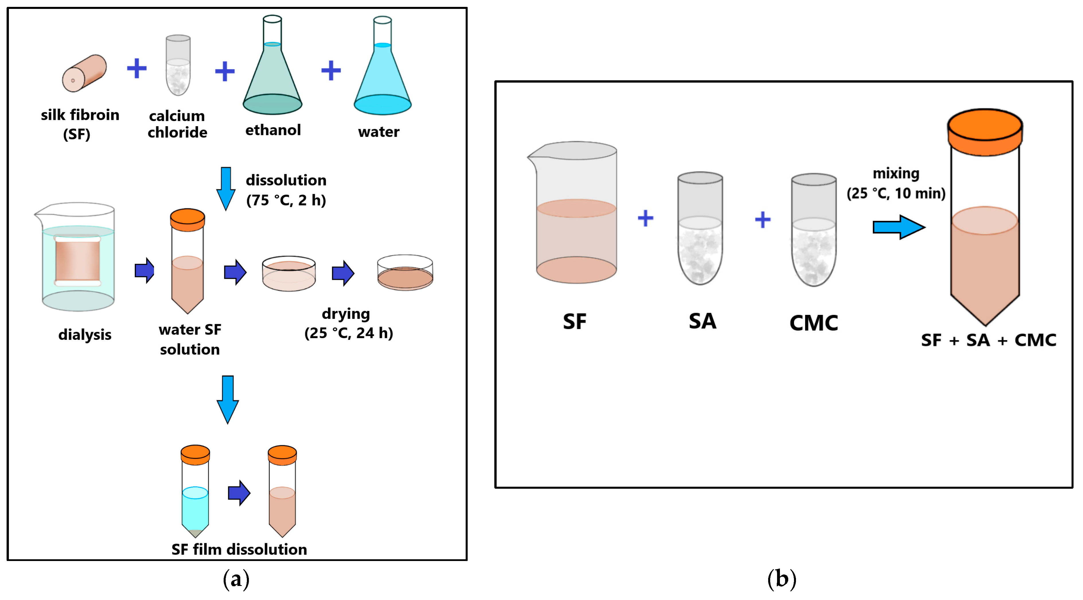
The aqueous solution of SF was prepared according to the method described in [
14]. Surgical suture threads were used to obtain an aqueous SF solution (Mosnitki, Moscow, Russia). A diagram of the process is shown in
Figure 1a. The filaments were dissolved in an aqueous mixture based on CaCl
2 (Reagent, Moscow, Russia), C
2H
5OH (Reagent, Moscow, Russia), and H
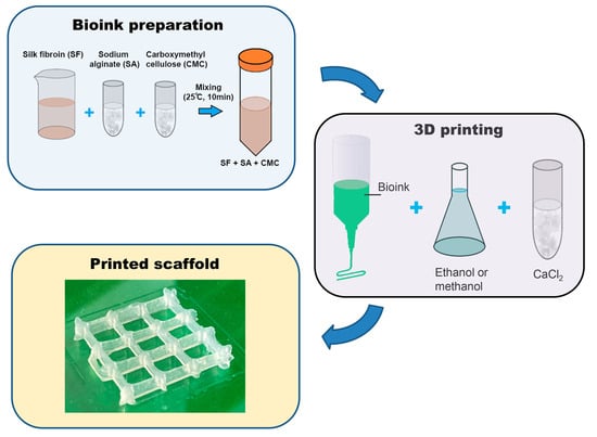
2O in a molar ratio of 1:2:8, respectively. The resulting mixture was kept at a temperature of 75 °C for 2 h in a water bath until the silk was completely dissolved. To remove calcium chloride, a dialysis solution was used against water. The water was changed 5 times during one day. The resulting supernatant was centrifuged. To obtain dry silk fibroin, the solution was poured onto Petri dishes and dried at room temperature until the water completely evaporated. Next, the dry silk fibroin was dissolved in distilled water to a final protein concentration of 2.5 or 5%.
A pure alginate and mixtures of alginate and carboxymethyl cellulose solutions with different concentration of silk fibroin (SF 2.5% and SF 5%) and alginate and CMC without silk fibroin (SF 0%) were prepared following the steps shown in
Figure 1.
2.2. Preparation of Bioinks
To prepare bioinks, SF was dissolved in distilled water at room temperature. After the complete dissolution of SF (final concentration 2.5% (
w/
v) or 5% (
w/
v)), carboxymethyl cellulose sodium (Sigma-Aldrich, St. Louis, MO, USA) was added to the SF solution at a concentration of 2% (
w/
v) and alginate (Alg) (alginic acid sodium salt from brown algae (Sigma-Aldrich, St. Louis, MO, USA) at a concentration of 1% (
w/
v) with intensive stirring until all components were completely dissolved (
Figure 1b). Thus, the bioink contained SF 2.5%, CMC, and alginate (sample SF 2.5%) or 5% SF, CMC, and alginate (sample SF 5%). The resulting bioinks were left at 4 °C for 2 days to remove air bubbles. The bioinks obtained by dissolving 2% CMC and 1% Alg in water without SF were used as a control (SF 0%).
After printing, the obtained scaffolds were fixed by treatment with a 2% solution of calcium chloride (Reagent, Moscow, Russia) for 5 min and methyl or ethyl alcohol for 10 min.
2.3. Rheology of Solutions
The rheological properties of the obtained bioinks were studied with the help of a rheometer MCR301 (Anton Paar, Stuttgart, Germany) in a CC17-SN8019970cylindrical measuring device. The tests were carried out in shear mode (at a constant rotation speed) with a step-by-step decrease in the deformation rate from 1000−1 to the minimum possible rate.
2.4. Printing
For the formation of volumetric scaffolds, the method of 3D extrusion printing was used with the help of a 3D bioprinter Dr. INVIVO (ROKIT Healthcare, Seoul, South Korea). By means of a pneumatic dispenser with a syringe, ink was supplied to a movable printing table. A 10 mL syringe with a 24G needle attachment was used for printing (24G needle nominal inner diameter = 0.311 mm, outer diameter = 0.566 mm according to Needle Gauge Chart).
The print model was created in the Autodesk Fusion 360 program and translated into a suitable G-code for the printer using NewCreatorK (version 1.57.71).
The following parameters were used for printing: printer type—Bio (print area width = 100 mm; print area depth = 100 mm; print area height = 90 mm) slicer type—Edislicer; nozzle size = 0.3 mm; print speed = 4 mm/s; input flow = 100%; printing temperature = 25 °C; infill pattern = lines.
The printer was controlled using a touch screen located on the top of the outside of the device; the pre-installed software was Android OS 7. The scaffolds obtained by 3D printing were treated with methyl or ethyl alcohol for 2 h to form an insoluble beta-folded structure of silk fibroin and 3% (w/v) calcium chloride solution for crosslinking sodium alginate. After precipitation, the scaffolds were thoroughly washed several times with distilled water.
2.5. IR-Fourier Spectroscopy
The molecular structure of the obtained scaffolds was evaluated with a IR Prestige-21 Fourier transform infrared spectrometer (FTIR) (Shimadzu, Tokyo, Japan) in the transmittance mode in the range of 4000–600 cm−1 with a resolution of 2 cm−1.
2.6. Print Quality
To determine the print quality, a 3D model of a grid with square cells with a given side length of 8 mm was used, according to which the matrices were printed. The suitability of formulations for 3D printing (
Pr, from the English printability) was evaluated using the formula:
where
L is the inner perimeter of the cell, and
A is the area of the cell.
For a perfectly square cell, the printability is 1. If the ink has insufficient viscosity, the shape of the cells will be more rounded, and the
Pr will decrease. FOr the same structures, the reduction in the pore area was estimated using the formula:
where
S is the actual area of the support, and
S0 is the expected area.
The sagging of the thread was also evaluated according to the method proposed by Therriault and co-authors [
40]. To do this, we used a comb with a variable distance between the teeth from 1 to 5 mm in increments of 1 mm. The studied gels were applied to its surface in the form of a continuous thread and the sagging factor (collapse factor) was determined using the formula:
where
A is the actual area under the gel thread, and
A0 is the expected area.
The parameters (printability and collapse factor) were measured using the ImageJ program.
2.7. Dynamic Mechanical Analysis
Dynamic mechanical analysis of compression samples was carried out at the DMA 141 242 C installation (NETZSCH, Selb, Germany) at a constant temperature of 37 °C under a mechanical load of Fd = 0.5 N and with a frequency which varied from 0.1 to 100 Hz. The base height of the sample was 6 mm, and the diameter was 10 mm. The dependence of the elastic modulus E’(f) on the frequency of the load was constructed according to the experimental data obtained. Cubic spline interpolation was used to process the experimental curves.
2.8. Scanning Electron Microscopy
The microstructure of the scaffolds obtained by 3D printing was analyzed using a Supra-55VP scanning electron microscope (Carl Zeiss, Oberkochen, Germany). Before the scanning electron microscopy (SEM) investigation, the samples were glued onto special holders and sputtered with Pt.
2.9. Swelling
To assess the effect of silk fibroin content and the methods of beta-folding formation, the swelling of matrices in distilled water was studied. For this purpose, the matrices were dried in a thermostat at a temperature of 30 °C, weighed, and immersed in distilled water. The degree of swelling was calculated by the formula:
where
m(
t) is the mass of the matrix at time
t, and
m0 is the mass of the completely dried matrix.
To estimate the swelling rate, measurements were carried out after 1, 2, and 3 h, as well as 24 h hours after the beginning of swelling at room temperature.
2.10. In Vitro Studies
The printed scaffolds were dried until water was completely removed, sterilized under ozone exposure for 90 min, and then incubated in a complete DMEM/F12 nutrient medium (Dulbecco’s modified Eagle’s medium, Lonza, St. Louis, MO, USA) containing 10% (by volume) thermally inactivated fetal bovine serum (FBS; HyClone, St. Louis, MO, USA), 1% L-glutamine, 50 units/mL of penicillin, and 50 mcg/mL of streptomycin for 3 days. The resulting incubation medium was examined for cytotoxicity with respect to mesenchymal stromal cells.
Human FetMSCs cell line (human mesenchymal stromal cells—Institute of Cytology, St. Petersburg, Russia) was used to study cytotoxicity. Cells were cultured in a CO2 incubator at 37 °C in a humidified atmosphere containing air and 5% CO2 in a DMEM/F12 nutrient medium (Dulbecco’s modified Eagle’s medium; Lonza, St. Louis, MO, USA) containing 10% (by volume) thermally inactivated fetal bovine serum (FBS; HyClone, St. Louis, MO, USA), 1% L-glutamine, 50 units/mL of penicillin (Sigma-Aldrich, Steinheim, Germany), and 50 mcg/mL of streptomycin (Sigma-Aldrich, Steinheim, Germany).
For the experiment, 5 × 10³ cells/100 µL/well were sown in 96-well plates and cultured for 24 h for their attachment. A day later, the medium was drained and a complete nutrient medium was added to the wells after incubation with printed samples fixed with calcium chloride, in addition to ethanol or methanol for 3 days. At the end of the incubation period (3 days), the medium was removed and 50 µL/well of DMEM/F12 medium with MTT (3-(4,5-dimethylthiazole-2-yl)-2,5-diphenyl-tetrazolium bromide) (0.1 mg/mL) was added. The cells were incubated in a CO2 incubator for 2 h at 37 °C. After removal of the supraplastic fluid, formazane crystals formed by metabolically viable cells were dissolved in dimethyl sulfoxide (50 µL/well) and transferred to clean wells, and then the optical density was measured at 570 nm on a flatbed spectrophotometer.
2.11. Statistical Analysis
All experiments were repeated 5 times. A GraphPad Prism 8 two-way ANOVA and Tukey test were used to analyze the statistically significant differences between samples. Data were considered to be statistically important when p < 0.05.
3. Results and Discussion
SF consists of two main chains, a heavy (H-) chain and a light (L-) chain, which are linked via disulphide bonds to form an H-L complex [
41,
42]. P25 (25 KDa) is a glycoprotein which includes Asn-linked oligosaccharide chains and is hydrophobically linked to the H-L complex [
43]. The H-chain, L-chain, and P25 are the three polypeptides that form a cocoon around B. mori and are found at a molar ratio of 6:6:1, respectively [
44]. The amino acid sequence of the H-chain consists of Glycine (45.9%), Alanine (30.3%), Serine (5.3%), and Valine (1.8%), as well as 4.5% of 15 other types of amino acids [
45].
Alginate is composed of (1-4)-linked β-Dmannuronic (M) and α-Lguluronic acids (G). This material is a negatively charged linear copolymer (M and G blocks), which is soluble in water. The G-block of this material assists in the formation of gels and GM and M blocks by improving their flexibility.
Carboxymethyl cellulose is an anionic water-soluble biopolymer derived naturally or through a chemical reaction with cellulose. It is a copolymer of β-D-glucose and β-D-glucopyranose-2-O-(carboxymethyl)-monosodium salt, which are connected via β-1,4-glucosidic bonds [
46].
SF, sodium alginate, and CMC are polar solutes which are soluble in water. These three materials carry out intermolecular action through the formation of hydrogen bonds and, consequently, can be used to produce compatible, blended, hybrid hydrogels [
43,
44,
45].
3.1. Rheological Properties
Among the other types of printing, extrusion-based bioprinting has attracted a lot of attention due to its ability to use a wide range of materials and compositions [
47].
Printability in 3D extrusion printing is defined as (1) the extrudability of bio-ink during extrusion, characterized by rheological properties, and (2) the formability of filaments after extrusion, characterized by the accuracy of the shape of filaments and structures. The rate of gelation can be controlled by adjusting the rheological properties of hydrogels by adding a viscosity modifier [
48], or an external crosslinking agent [
49], or through temperature changes [
50,
51]. However, improving viscosity does not always enhance the biocompatibility aspect of a bioink. For example, increasing viscosity will improve print quality and shape accuracy, but when increasing the viscosity of bioinks, it is also necessary to increase the extrusion pressure, which is harmful to the living cells contained in the bioink.
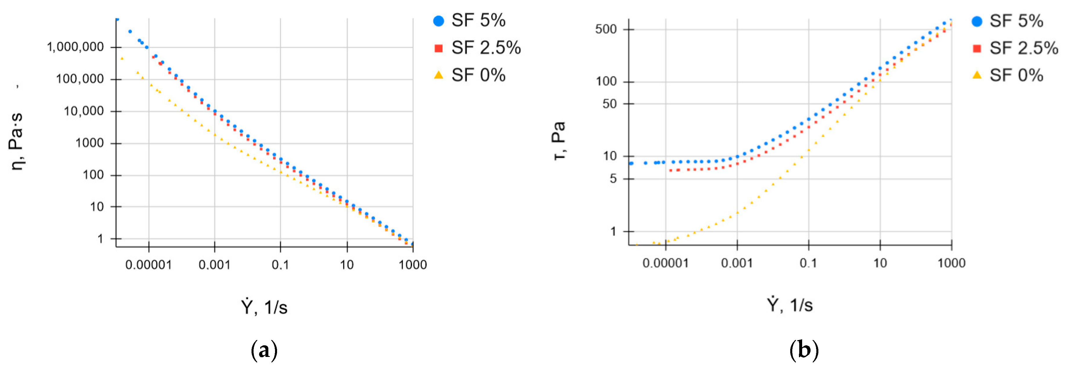
The rheological properties of bioinks play a crucial role in 3D printing processes. The aim of this experiment was to analyze the rheological differences from different silk fibroin concentrations. When the hydrogel is extruded under pressure through a small nozzle, it experiences shear stress. It should be in a solution state as it passes through the nozzle, but once extruded, it should retain the printed shape.
Figure 2 shows the dependence of the effective viscosity and shear stress of the studied solutions based on SF on the shear rate. With an increase in the shear rate, the viscosity of all gels decreases (
Figure 2a), indicating the destruction of the original structure and the formation of a new structure due to the orientation of polymer molecules along the shear field. At the same time, the shear stress increases as the shear rate increases (
Figure 2b). An investigation of the rheological properties, which are crucial for determining the suitability of hydrogels for 3D printing, has shown that SF-based hydrogels are able to shift [
52,
53]. This means that the viscosity of the hydrogel decreases with the increasing shear rate.
Bioinks can be characterized as plastic and thixotropic at all of the studied concentrations of SF. As the proportion of SF in the ink increases, the viscosity of the solutions increases, that allows the gel to retain its shape during printing. As result, this is a prerequisite for using the gel as an ink in 3D bioprinting [
54,
55].
The overall cell viability of scaffolds manufactured by 3D bioprinting based on extrusion depends on the shear stress experienced by the encapsulated cells. There are data in the literature comparing cell viability and print quality based on the rheological characteristics of bioinks. The creation of scaffolds with a higher percentage of solids content can provide better shape accuracy [
56], as this increases the viscosity of the composition. However, due to the higher dosing pressure required, the small nozzle diameter, and the corresponding higher shear stress, this can adversely affect the overall viability of the cells.
Based on the analysis of the literature data [
57] and our own research, we can assume that the rheological properties obtained for the bioinks we developed will lead to a high print quality and a sufficiently high viability of the cells cultured inside the printed scaffolds.
3.2. Printability
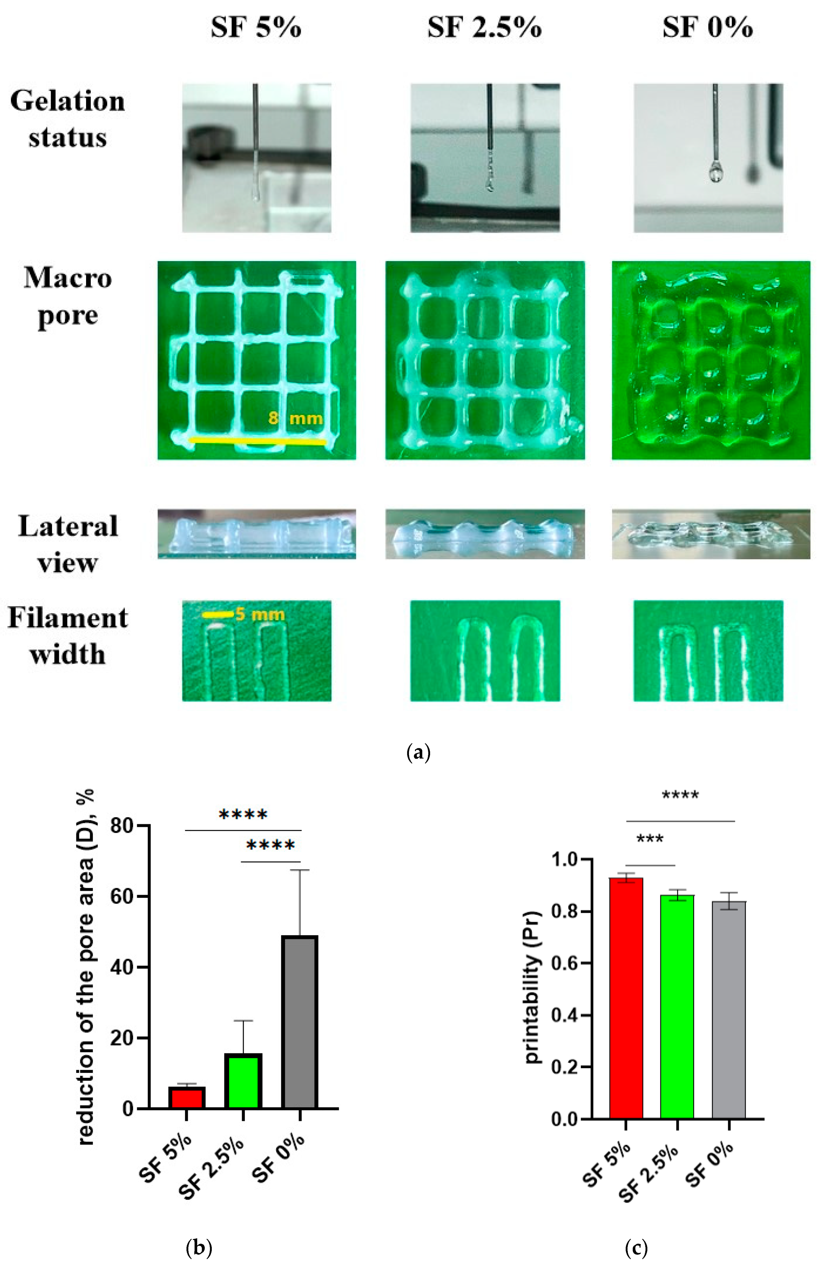
The design of the cubic frame was chosen as a model system for determining the optimal composition of the hydrogel to achieve a high morphological accuracy in 3D printing (
Figure 3a). These optimal component ratios can be used to print larger and more complex scaffolds. In our study, we aimed to develop hydrogels that were optimized for 3D printing using SF-based formulations with a well-defined gelation time, making them suitable for application in regenerative medicine. The size of the objects prepared with the help of the 3D printer was measured using a piece of software, and a comparison was made between the dimensions of the designed 3D objects and the actual printing result (
Figure 3b). The measurements show a close similarity between the modeling and the results, especially in the group containing SF 5%. In the groups with a lower concentration of SF or without SF, it has been demonstrated that the filament diameter of printed products is larger, while the height is smaller than the design’s dimensions. This phenomenon can be explained by the fact that the ink is squeezed out of the nozzle and spreads slightly to the sides before being fixed with calcium chloride or alcohol.
Previously, in the literature, an ink based on CMC and alginate was presented [
58]. The authors managed to significantly improve the print quality by increasing the concentrations of alginate and CMC in the hydrogel. Of course, the viscosity of such inks increased significantly, but a dense mesh of polymers and a negatively charged alginate would negatively affect the spreading and migration of cells inside such hydrogels. SF is known to consist mainly of amino acids such as alanine (Ala), glycine (Gly), serine (Ser), and others. These amino acids form hydrogen bonds within the silk molecule that are a crucial factor determining the strength and stability of the silk. Hydrogen bonds can take various forms within the silk molecule, and among them -OH (hydroxyl) groups play a significant role in the formation of hydrogen bonds [
59].
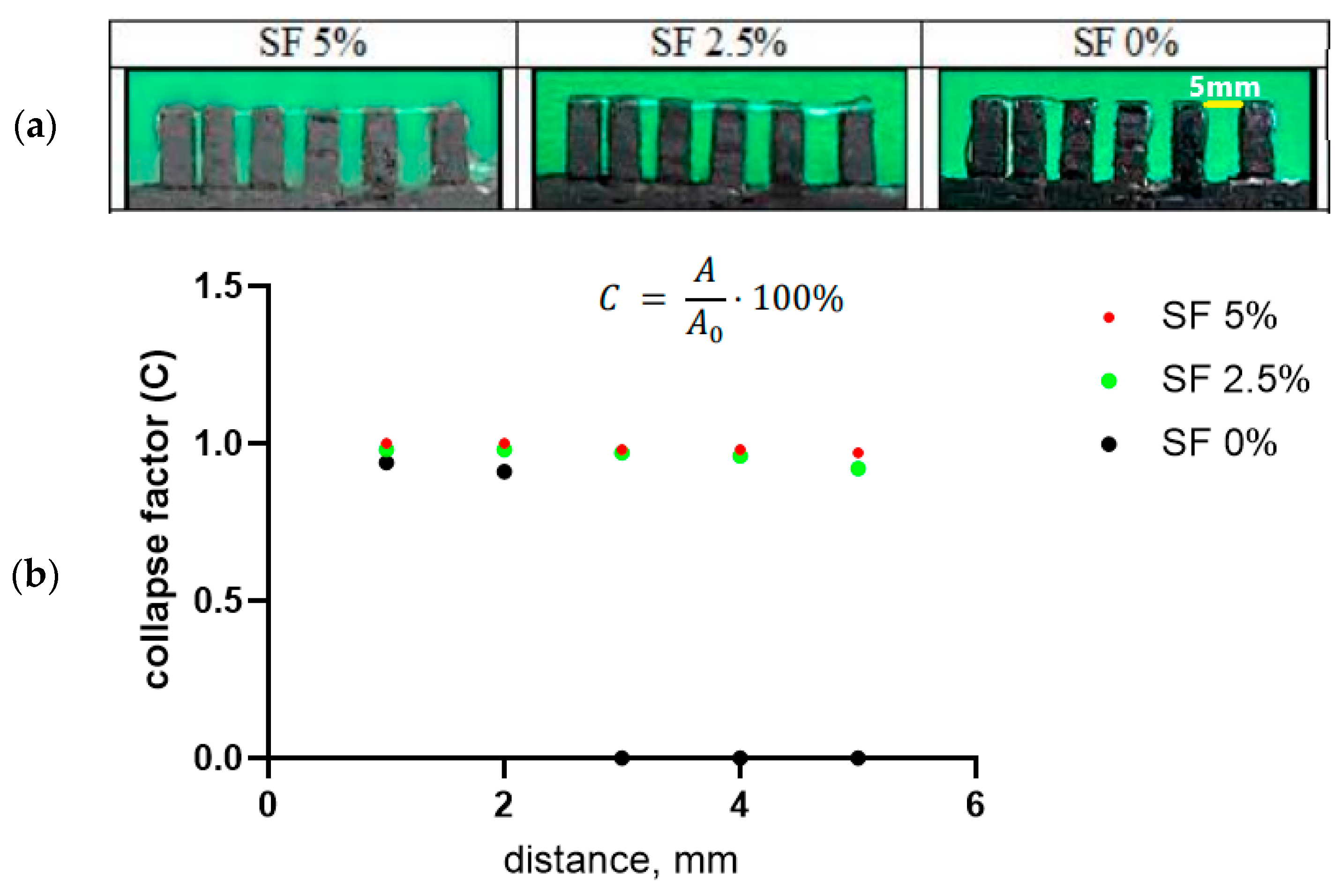
The collapse factor of the gel thread makes it possible to assess the stability of a separately applied strip of composition against sagging in the air (
Figure 4a). To do this, one strip of gel is applied to a comb with a variable distance between the teeth (from 1 to 5 mm, step 1 mm) using a printer. In this case, the printer provides the same application conditions—the volume of ink supplied, the speed of movement of the syringe, the pressure on the piston, and the distance between the syringe and the comb. In this case, the gel was applied at a syringe movement speed of 4 mm/s at an input flow value of 100%. With sufficient viscosity, the thread sags minimally; such a composition ensures a satisfactory print quality (
Figure 4b). A high level of subsidence (up to the interruption of the thread) indicates that the ink viscosity is too low.
Thus, a gel with a 5% content of SF has the most satisfactory print quality indicators, which allows us to conclude that this composition is optimal for use as a bioink. The suitability for printing and the collapse factor of this composition are close to one, and the reduction in the cell area of the printed structure is minimal among the three studied gels. At the same time, there is a tendency for the print quality indicators to deteriorate with a decrease in the proportion of silk fibroin in the ink composition.
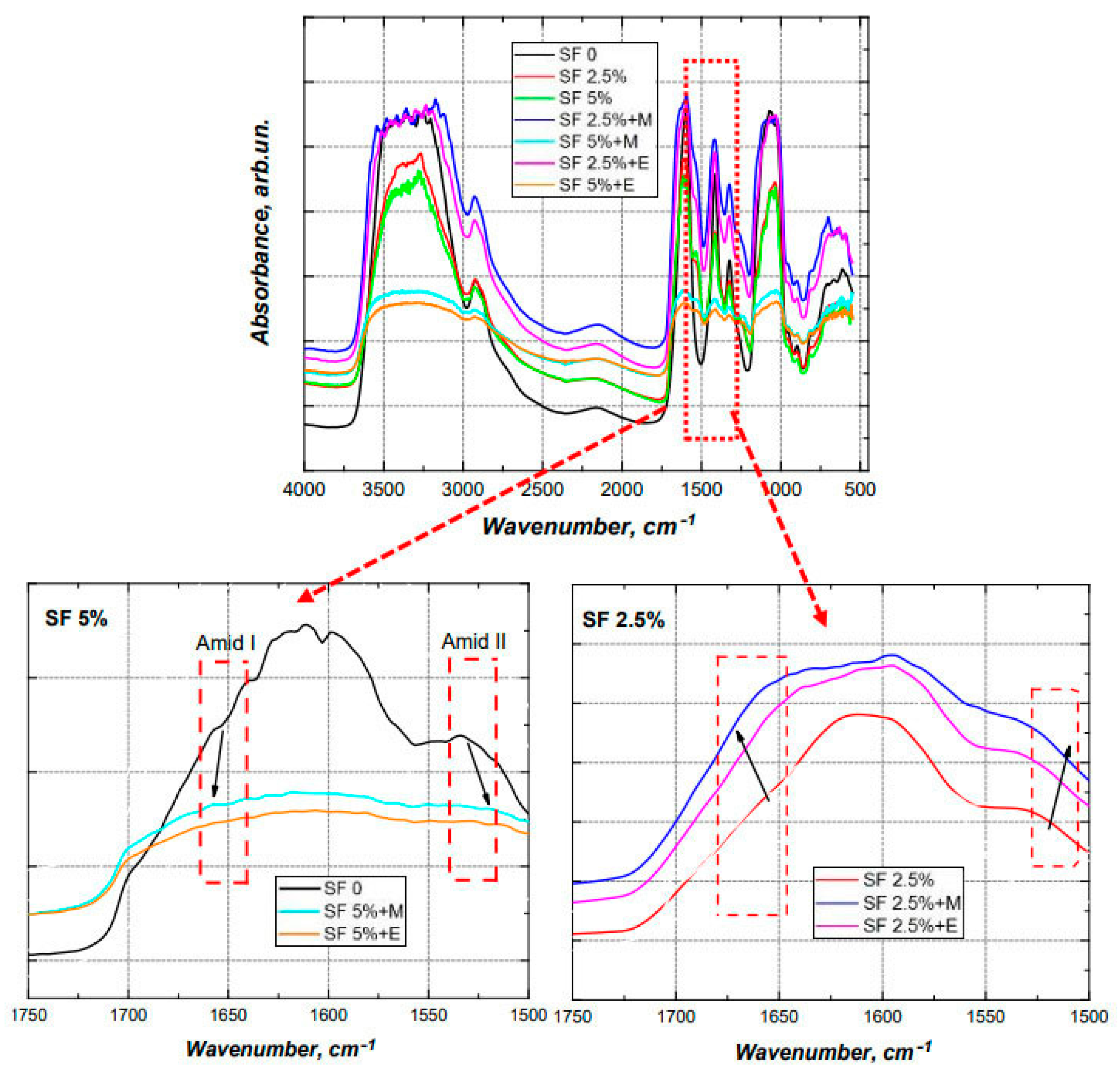
3.3. FTIR-Spectroscopy
In order to induce the formation of a crystalline β-structure, the scaffolds were treated with alcohols. In the present study, the effect of methyl and ethyl alcohols on the conformational transition of silk fibroin was compared (
Figure 5). It is well known that, when silk fibroin is treated with polar alcohol, a conformational transition of the silk fibroin solution from a random spiral crystallization to β-sheets crystallization occurs [
59]. As a result of this crystallization, physical cross-links are formed in the silk structure, which ensure the insolubility of the silk fibroin in water. Um and co-authors proposed a crystallization mechanism [
60]. According to this mechanism, polar groups of alcohols attract water from silk fibroin molecules leading to an increased aggregation of hydrophobic amino acids, particularly Gly and Ala, in the internal structure of the silk fibroin molecules. The polarity of the alcohol was an important factor that regulated the transition of the silk fibroin from a random spiral crystallization to β-sheets. It was also previously reported that, as the length of the carbon chain increased, the polarity of the alcohol decreased, which led to an increased hydrophobic interaction between the alcohol and the silk fibroin molecules [
23]. Consequently, ethanol can contribute to a more rapid crystallization of the β-layer of silk fibroin compared with methanol.
Changes in the structure of the scaffolds were investigated using Fourier transform IR spectroscopy on samples with different compositions before and after treatment with alcohols (
Figure 5) [
61].
The characteristic absorption peaks of sodium alginate can be seen at 1150 cm
−1 (valence vibrations of the C-OH fragment), 1100 cm
−1, 1420 cm
−1 (valence symmetric vibrations of the polyanion carboxyl group), 1590–1610 cm
−1 (valence antisymmetric vibrations of the polyanion carboxyl group), and 2890–2920 cm
−1, and those of CMC can be seen at 1327 cm
−1 (deformation vibrations CH
2), 1610–1620 cm
−1 (valence vibrations carboxyl group), 2914–2939 cm
−1, and 3427 cm
−1 [
62,
63,
64].
Characteristic signals indicating the formation of a β-sheets structure were detected, including the band at 3070–3600 cm
−1 (fluctuations of N-H and O-H peptide groups), the sharp drop in absorption by 1700 cm
−1, the expansion of the band at 1590–1620 cm
−1 to the boundaries of 1560–1650 cm
−1, the fact that 1268 cm
−1 shifted by 1230 cm
−1 (amid III), the higher absorption at the interval 1070–1150 cm
−1, a shift of 1540 cm
−1 by 1518 cm
−1 (amid II), and the shift of 1655 cm
−1 to 1670–1674 cm
−1 (amid I) [
65].
The spectra of the films with the same content of silk fibroin after the conformational transition, regardless of which alcohol they were treated with, coincide with each other, which confirms the conformational transition of silk fibroin when interacting with both alcohols.
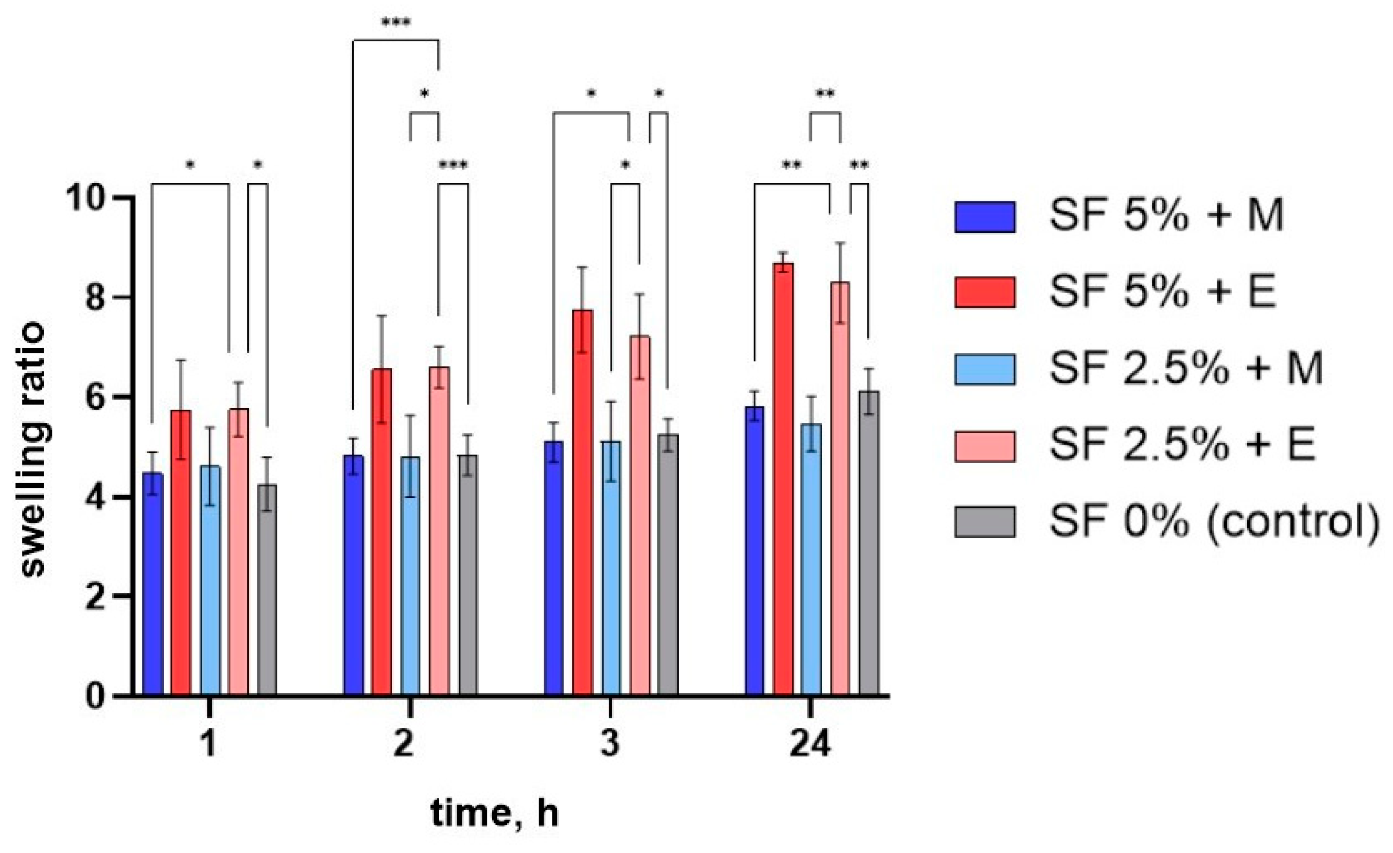
3.4. Swelling
SF dissolves well in aqueous solutions. Therefore, for further use of the printed scaffolds in vitro or in vivo, it is necessary to transform it into an insoluble form. An additional advantage of SF is the simplicity of its conversion into an insoluble form. When SF is treated with solutions of ethyl or methyl alcohol, SF is conformationally converted into β-sheets that are insoluble in water [
65]. In our work, we studied the effect of ethanol and methanol on the ability of these alcohols to facilitate the conformational transition of SF in the presence of CMC and alginate.
To assess the swelling of printed scaffolds made by different methods, their degree of swelling was determined. For this purpose, the printed scaffolds were dried at room temperature for 48 h, weighed, and then immersed in water and the change in mass was tracked over time. Measurements were made 1, 2, 3, and 24 h after the beginning of swelling. After a day, all of the studied scaffolds were found to have swelled as much as possible (after 24 h they no longer absorbed water). The dynamics of the swelling of the studied scaffolds are shown in
Figure 6.
The greatest degree of swelling was noted for matrices made of a gel with a 5% content of silk fibroin treated with ethyl alcohol—fully swollen samples are, on average, 8.7 times heavier than those in dried form. In the presence of alcohols, silk fibroin changes from its amorphous hydrophilic form to a crystalline hydrophobic one. As a result, it becomes insoluble in water, and its ability to absorb water is also reduced. This may indicate that the proportion of β-sheet structure formed after the SF is treated with ethanol is lower than when it interacts with methanol.
The samples had a lower degree of swelling at all stages after the methanol treatment compared to that after the ethanol treatment. Ethanol has a lower polarity O-H bond, so reactions associated with the destruction of this bond proceed more slowly. During the interaction of alcohols with amorphous silk fibroin, polar groups of alcohols attract water from silk fibroin molecules, leading to an increased aggregation of hydrophobic amino acids (especially glycine and alanine), which are part of protein molecules. Thus, by using alcohols of different polarities, it is possible to regulate the formation of beta structures, and, hence, the ability of the product to swell [
59].
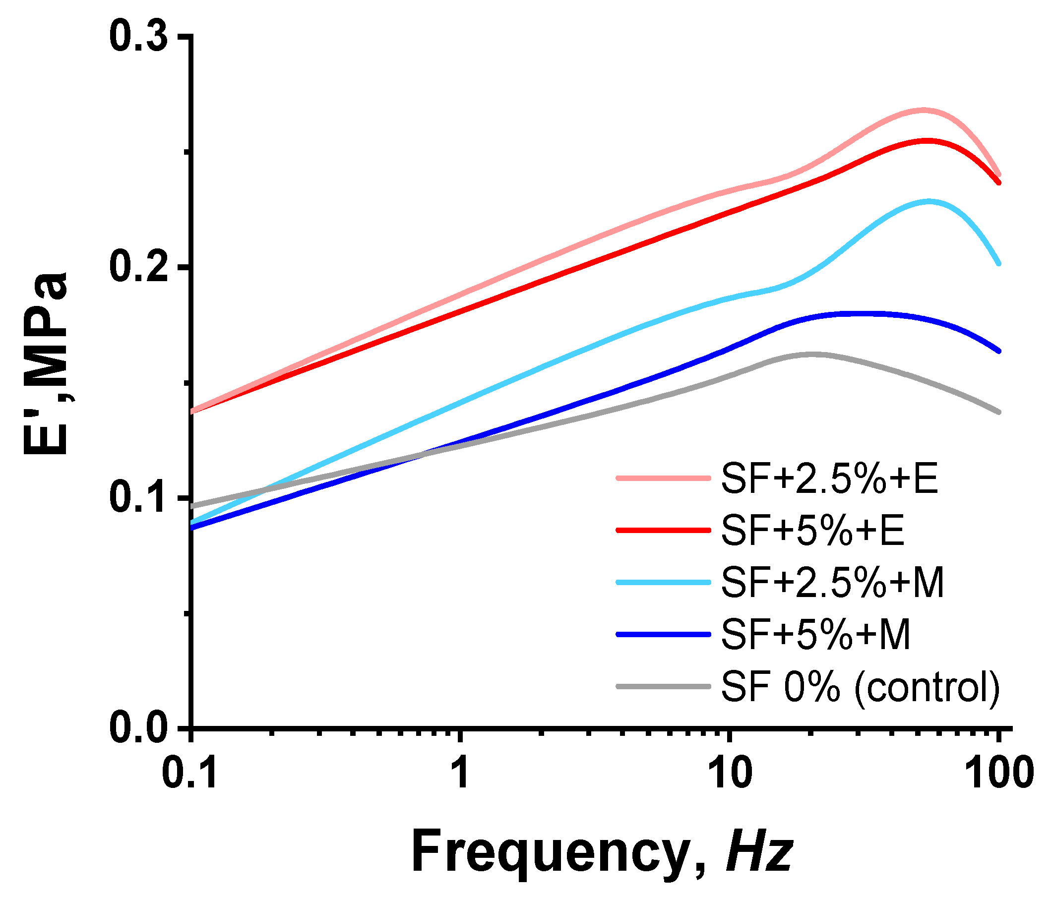
3.5. Dynamic Mechanical Analysis
The DMA data demonstrate an increase in the rigidity of printed structures when SF was added (
Figure 7). A higher SF content of 5% does not provide an increase in stiffness compared to a sample containing 2.5% SF. However, it is noted that the treatment of printed scaffolds with ethanol makes it possible to obtain more rigid scaffolds compared to scaffolds treated with methanol.
As previously noted, ethanol should contribute to the most rapid crystallization of the β-sheets of silk fibroin compared to methanol due to the longer length of its carbon chains, and, consequently, there should be an increased number of hydrophobic interactions between the alcohol and the silk fibroin molecules. In our study, it has been shown that, when treating the scaffold with ethanol, which has a longer carbon chain length compared to methanol, the elasticity of the scaffold decreases. This unexplained connection was also obtained in the work of Kaewpiroma and Boonsang [
59].
It would be more logical to expect that, with an increase in the concentration of SF in the composition of bioinks, the modulus would increase. However, we observe an inverse relationship. We explain the results obtained by the fact that with an increase in the concentration of SF, its ability to mix evenly with other components of bioinks, namely alginate and CMC, decreases. SF macromolecules, as well as sodium alginate and CMC, have a sufficiently large size, so it is quite difficult to obtain a uniform solution with an increase in the concentration of polymers. Naturally, with an increase in the concentration of SF, defects can form that will affect the modulus value.
When 2.5% SF is added to the bioinks, a more uniform distribution occurs and a grid structure may be created, providing a high modulus of elasticity. To clarify this assumption, the structure of the samples was studied using SEM.
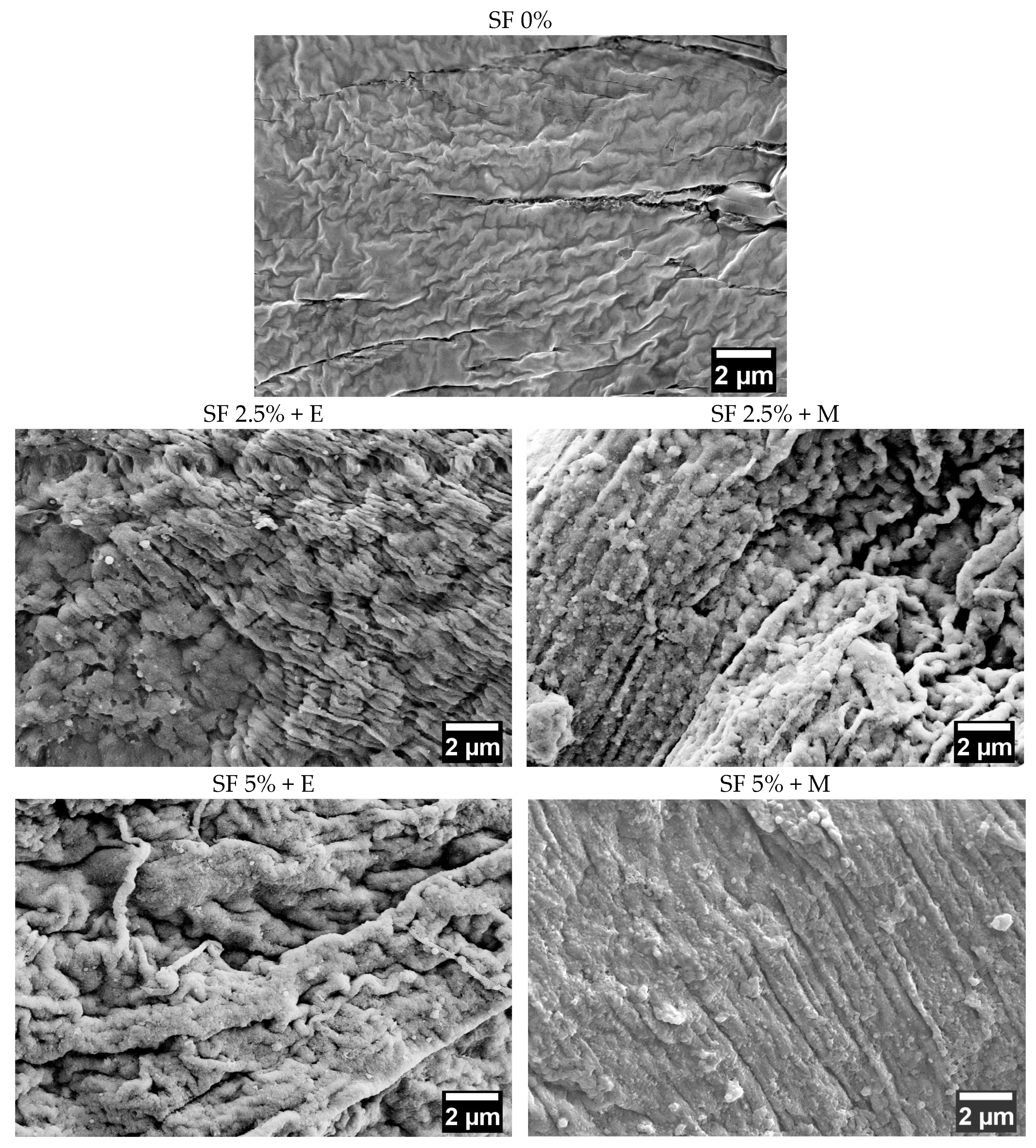
3.6. Scanning Electron Microscopy
The structure of the studied samples was investigated using the SEM technique.
Figure 8 shows the SEM images of the scaffolds which differ in their silk fibroin content and the method of inducing the silk fibroin’s conformational transition. There are significant differences between samples that do not contain SF and the rest: for all scaffolds with SF, the formation of an oriented parallel structure corresponding to the β-sheets form of SF is revealed. The control sample, made only of CMC and sodium alginate, does not have such a structure.
Controlling the alignment and orientation of the scaffold surface was earlier reported to represent a wide range of applications, including improving the structural properties of scaffolds in addition to enhancing the growth of cells in nanofiber scaffolds for tissue engineering [
66,
67]. Thus, aligning silk fibroin nanofibers along their longitudinal direction may also have promising applications in tissue engineering by mimicking natural tissues or organs.
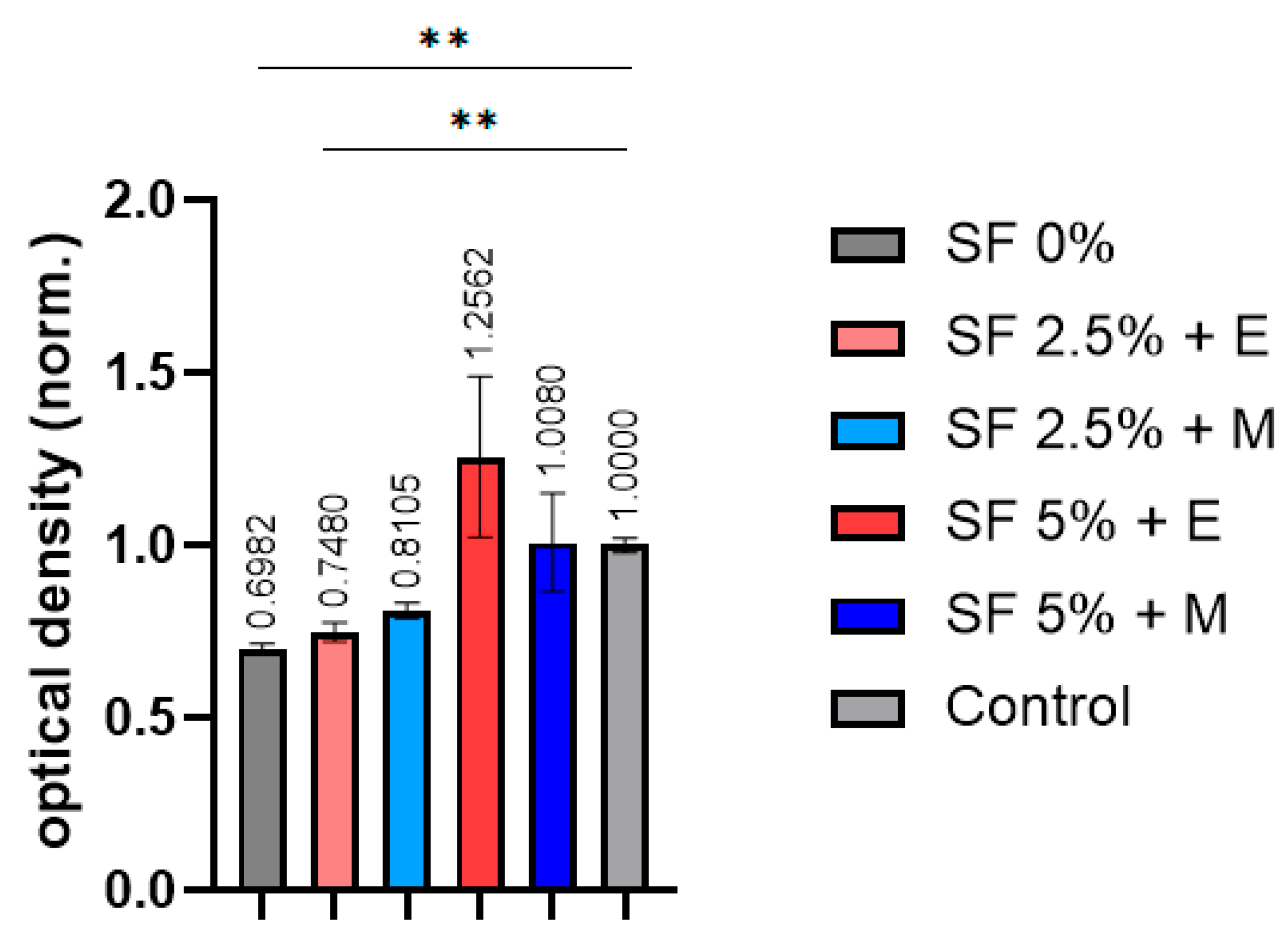
3.7. Cytotoxicity Test
To obtain functional and tissue-like structures, it is important to take into account the various stages of development that the printed scaffolds must go through. Cell viability is the very first step in evaluating the suitability of a scaffold for cell culture. Silk-based bioinks are known to play a key role in supporting the proliferation of cells within the printed construct [
68]. Its degradation rate can be precisely controlled, varying from weeks to years following implantation in vivo, which in turn depends on the scaffold type, the cross-linking agent, crystallization, and other factors involved. It follows from the MTT test results that an increase in the proportion of SF contributes to an increase in the biocompatibility of the scaffolds (
Figure 9).
In the samples printed without the addition of silk fibroin, the cell viability was found to be significantly lower than expected. The scaffolds with 2.5% silk fibroin provided more viable MSCs compared to the samples without SF, but this was still lower than expected. The scaffolds printed from bioinks with 5% silk fibroin provided a cell viability that was closer to what we expected. At the same time, the choice of alcohol does not have a negative effect on cell viability. The toxic effect of methanol on cells is known. The absence of a decrease in the viability of cells cultured in the medium after the incubation of the printed SF scaffolds in a nutrient medium indicates that methanol is only involved in the crystallization of silk fibroin into β-sheets and is not absorbed into the scaffolds. It is possible to say that, qualitatively, SF scaffolds offer a significant potential to be used in applications where cytocompatibility is required.
Indeed, significant differences compared with the control were only observed in samples based on CMC and alginate, as well as a sample containing CMC, alginate, and 2.5% silk fibroin. The decrease in cell viability in these samples is apparently due to the partial solubility of the components of these bioinks in the nutrient medium, which reduces the viability of cells cultured in such an incubation medium.


 ,
, 


