
Experimental Study on the Structural Performance of Glass-Fiber-Reinforced Concrete Slabs Reinforced with Glass-Fiber-Reinforced Polymer (GFRP) Bars: A Sustainable Alternative to Steel in Challenging Environments


Abstract
1. Introduction
2. Materials and Methods
2.1. Materials
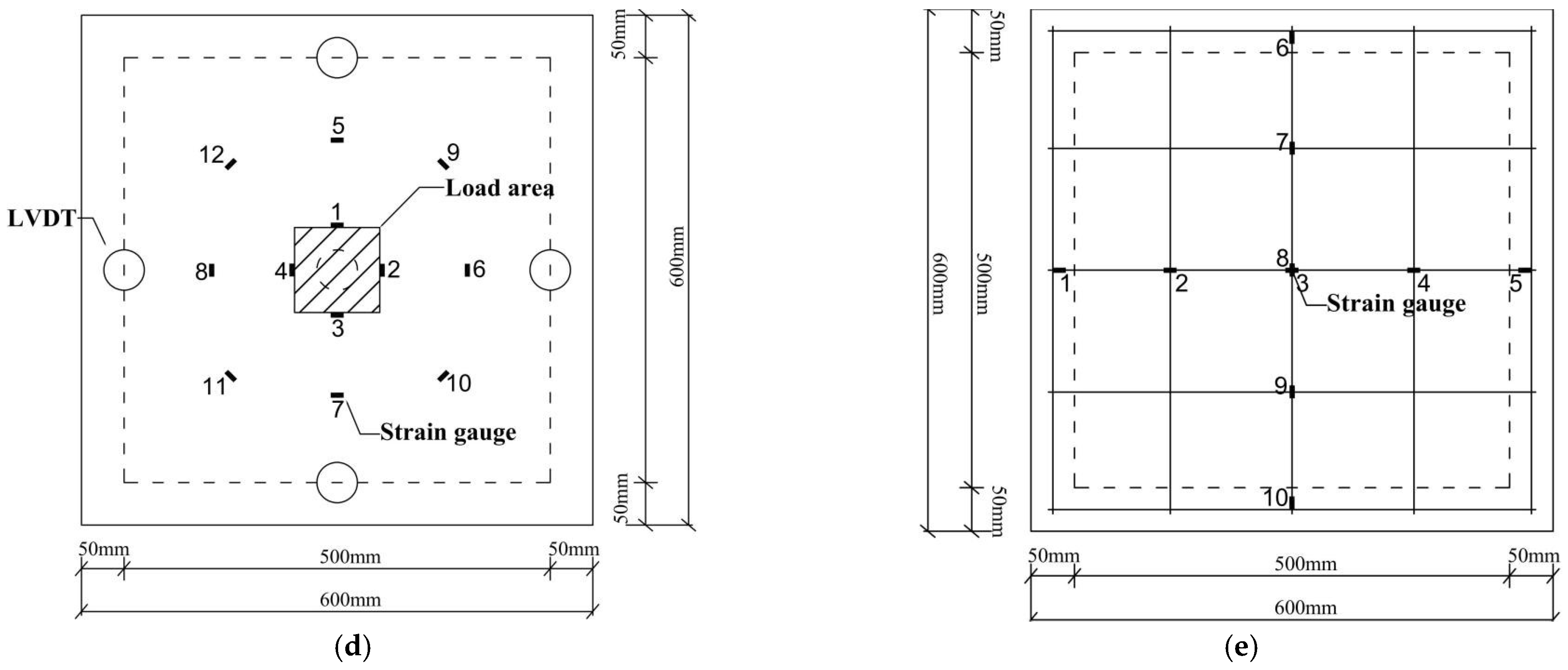
2.2. Test Design
3. Results
3.1. Load-Strain Behavior
3.2. Load-Deflection Behavior
4. Discussion
4.1. Crack Propagation and Fiber Contribution
4.2. Design of Flexural Strength
4.3. Hybrid Engineering Performance
5. Conclusions
- (1)
- The enhancement of concrete performance through the incorporation of fibers is particularly evident. GFRP-bar-reinforced GFRC slabs with 3% FVF, similar to steel-bar-reinforced GFRC slabs and SFRC slabs, exhibit a gradual load-deflection response and predictable crack propagation.
- (2)
- The differences in load capacity under bending conditions between GFRP-bar-reinforced GFRC slabs and steel-reinforced slabs are limited to a specific range. The similarities in load capacities are indicated by ratio values of 70% for crack load capacity and 86% for ultimate load capacity, respectively.
- (3)
- GFRCs exhibit consistent and monotonic improvements in flexural strength with increasing FVF. The flexural strength can be analyzed according to the provisions of the ACI standard, taking into account the strength-reduction factor, which is recommended to be 0.5.
- (4)
- When analyzed using current provisions, the hybrid system may offer additional benefits due to the synergistic effect of multiple reinforcement materials, enhancing the overall flexural capacity and ductility of the component, thereby improving structural performance in practical applications.
- (5)
- As demonstrated, the novel system significantly enhances bending capacity, crack resistance, energy absorption, structural ductility, and safety indicators compared to traditional steel-reinforced slabs. These enhancements are crucial for increasing the structural resilience of buildings exposed to diverse climatic conditions and will support the follow-up study.
Author Contributions
Funding
Institutional Review Board Statement
Data Availability Statement
Acknowledgments
Conflicts of Interest
References
- Wang, T.; Wu, Y.; Shi, L.; Hu, X.; Chen, M.; Wu, L. A structural polymer for highly efficient all-day passive radiative cooling. Nat. Commun. 2021, 12, 365. [Google Scholar] [CrossRef] [PubMed]
- Cabeza, L.F.; Chàfer, M. Technological options and strategies towards zero energy buildings contributing to climate change mitigation: A systematic review. Energy Build. 2020, 219, 110009. [Google Scholar] [CrossRef]
- Mishra, V.; Sadhu, A. Towards the effect of climate change in structural loads of urban infrastructure: A review. Sustain. Cities Soc. 2023, 89, 104352. [Google Scholar] [CrossRef]
- Bakeri, P.A. Analysis and Design of Polymer Composite Bridge Decks. Master’s Thesis, Massachusetts Institute of Technology, Cambridge, MA, USA, 1989. [Google Scholar]
- Grace, N.F.; Abdel-Sayed, G. Double tee and CFRP/GFRP bridge system. Concr. Int. 1996, 18, 39–44. [Google Scholar]
- Shield, C.K.; French, C.W.; Hanus, J.P. Bond of glass fiber reinforced plastic reinforcing bar for consideration in bridge decks. Spec. Publ. 1999, 188, 393–406. [Google Scholar]
- Fardis, M.N.; Khalili, H.H. FRP-encased concrete as a structural material. Mag. Concr. Res. 1982, 34, 191–202. [Google Scholar] [CrossRef]
- Kumar, S.V.; GangaRao, H.V.S. Fatigue response of concrete decks reinforced with FRP rebars. J. Struct. Eng. 1998, 124, 11–16. [Google Scholar] [CrossRef]
- Yao, S.Z. A shallow view of the development of FRP bridges. Bridge Constr. 1990, 3, 27–33. (In Chinese) [Google Scholar]
- He, J.; Liu, Y.; Chen, A.; Dai, L. Experimental investigation of movable hybrid GFRP and concrete bridge deck. Constr. Build. Mater. 2012, 26, 49–64. [Google Scholar] [CrossRef]
- Xin, H.; Mosallam, A.; Correia, J.A.F.O.; Liu, Y.; He, J.; Sun, Y. Material-structure integrated design optimization of GFRP bridge deck on steel girder. Structures 2020, 27, 1222–1230. [Google Scholar] [CrossRef]
- Wang, J.; Cheng, B.; Yan, X.; Zhang, K.; Zhou, Z. Structural analysis and optimization of an advanced all-GFRP highway bridge. Structures 2021, 34, 3155–3171. [Google Scholar] [CrossRef]
- Al-Rousan, R.Z. Impact of elevated temperature on the behavior of full-scale concrete bridge deck slabs reinforced with GFRP bars. Structures 2022, 43, 621–634. [Google Scholar] [CrossRef]
- Gao, C.; Fam, A. Rolling load fatigue experiment on a bridge deck reinforced with a new design of GFRP stay-in-place form. J. Compos. Constr. 2025, 29, 04024090. [Google Scholar] [CrossRef]
- BS 5400:1980; Steel, Concrete and Composite Bridges: Code of Practice for Fatigue, 1st ed. British Standards Institution: London, UK, 1980.
- CAN/CSA-S6-1922; Canadian Highway Bridge Design Code. CSA Group: Toronto, ON, Canada, 1922.
- ACI 440R-07; Report on Fiber-Reinforced Polymer (FRP) Reinforcement Concrete Structures. American Concrete Institute: Farmington Hills, MI, USA, 2007; 100p.
- ACI 440.6M-08; Specification for Carbon and Glass Fiber-Reinforced Polymer Bar Materials for Concrete. American Concrete Institute: Farmington Hills, MI, USA, 2008; 6p.
- CSA S807; Specification for Fiber-Reinforced Polymers. Canadian Standards Association: Mississauga, ON, Canada, 2010; p. 44.
- ACI 440.1R-15; Guide for the Design and Construction of Concrete Reinforced with FRP Bars. American Concrete Institute: Farmington Hills, MI, USA, 2015.
- Machida, A.; Uomoto, T. Recommendation for Design and Construction of Concrete Structures Using Continuous Fiber Reinforcing Materials; Japan Society of Civil Engineers: Tokyo, Japan, 1997. [Google Scholar]
- Saadatmanesh, H.; Ehsani, M.R. RC beams strengthened with GFRP plates. I: Experimental study. J. Struct. Eng. 1991, 117, 3417–3433. [Google Scholar] [CrossRef]
- Mirmiran, A.; Shahawy, M. Behavior of concrete columns confined by fiber composites. J. Struct. Eng. 1997, 123, 583–590. [Google Scholar] [CrossRef]
- Mirmiran, A.; Shahawy, M.; Samaan, M. Strength and ductility of hybrid FRP-concrete beam-columns. J. Struct. Eng. 1999, 125, 1085–1093. [Google Scholar] [CrossRef]
- Teng, J.G.; Chen, J.F.; Smith, S.T.; Lam, L. FRP: Strengthened RC Structures; Wiley: Hoboken, NJ, USA, 2002. [Google Scholar]
- Teng, J.G.; Lam, L. Behavior and modeling of fiber reinforced polymer-confined concrete. J. Struct. Eng. 2004, 130, 1713–1723. [Google Scholar] [CrossRef]
- Jiang, Z.; Li, S.; Xie, J.; Tan, Y.; Lu, Z.; Wang, Y.; Liu, W.; Zhao, C. Degradation of prestressed GFRP bars embedded in seawater–sea sand geopolymer mortars under hydrothermal seawater aging. J. Compos. Constr. 2024, 28, 04024040. [Google Scholar] [CrossRef]
- Hosseini, S.M.; Mousa, S.; Mohamed, H.; Benmokrane, B. Long-term durability of nonpultruded curvilinear GFRP bars exposed to an alkaline environment: Experimental studies and modeling. J. Compos. Constr. 2024, 28, 04024005. [Google Scholar] [CrossRef]
- Vaculik, J.; Visintin, P.; Lucas, W.; Griffith, M.C. Durability of near-surface-mounted FRP-to-clay brick masonry retrofits under environmental exposure. J. Compos. Constr. 2020, 24, 04019058. [Google Scholar] [CrossRef]
- AlHamaydeh, M.; Awera, Y.; Elkafrawy, M. Axial compressive behavior of slender circular columns made of green concrete and double layers of steel and GFRP reinforcement. J. Compos. Constr. 2023, 27, 04023050. [Google Scholar] [CrossRef]
- Mehany, S.; Mohamed, H.M.; Benmokrane, B. Flexural strength and serviceability of GFRP-reinforced lightweight self-consolidating concrete beams. J. Compos. Constr. 2022, 26, 04022020. [Google Scholar] [CrossRef]
- Teng, J.C.; Yin, Z.Y.; Song, D.B.; Jin, Y.F.; Chen, W.B.; Dai, J.G. Utilization of sand-filled FRP tubular pile retaining wall with sand back fill adjacent to strip footing: Model study. Acta Geotech. 2025. [Google Scholar] [CrossRef]
- Yang, Z.M.; Chen, J. Seismic Performance of hollow section concrete-filled GFRP tubular columns under monotonic loads and cyclic loads. Thin-Walled Struct. 2025, 206, 112705. [Google Scholar] [CrossRef]
- Ayoub, M.; Hasan, H.A.; Neaz Sheikh, M.; Hadi, M.N. Experimental behavior of GFRP bar–reinforced CFRP strip tie–confined normal-strength concrete columns under different loading conditions. J. Compos. Constr. 2023, 27, 04023018. [Google Scholar] [CrossRef]
- Zhou, C.; Wang, W.; Zheng, Y.; Cheng, Y.; Wu, Z. Crashworthiness design of GFRP bar reinforced concrete bridge pier subjected to truck collision. Case Stud. Constr. Mater. 2023, 18, e02205. [Google Scholar] [CrossRef]
- Tefera, G.; Adali, S.; Bright, G. Mechanical behavior of GFRP laminates exposed to thermal and moist environmental conditions: Experimental and model assessment. Polymers 2022, 14, 1523. [Google Scholar] [CrossRef]
- Iqbal, M.; Zhang, D.; Jalal, F.E. Durability evaluation of GFRP rebars in harsh alkaline environment using optimized tree-based random forest model. J. Ocean. Eng. Sci. 2022, 7, 596–606. [Google Scholar] [CrossRef]
- Mirdarsoltany, M.; Abed, F.; Homayoonmehr, R.; Alavi Nezhad Khalil Abad, S.V. A comprehensive review of the effects of different simulated environmental conditions and hybridization processes on the mechanical behavior of different FRP bars. Sustainability 2022, 14, 8834. [Google Scholar] [CrossRef]
- Gonilha, J.A.; Correia, J.R.; Santos, M.S.; Ferreira, J.G.; Branco, F.A.; Gomes, R.C. GFRP composite culverts for hydraulic and agricultural underpasses: Structural behavior, design, and application. J. Compos. Constr. 2022, 26, 04022026. [Google Scholar] [CrossRef]
- Hassanli, R.; Youssf, O.; Manalo, A.; Najafgholipour, M.A.; Elchalakani, M.; del Rey Castillo, E.; Lutze, D. An experimental study of the behavior of GFRP-reinforced precast concrete culverts. J. Compos. Constr. 2022, 26, 04022043. [Google Scholar] [CrossRef]
- Wootton, N.; Fam, A.; Green, M.; Jawdhari, A.; Sarhat, S. Field testing and dynamic response of full-scale GFRP-reinforced concrete guideway under monorail train. J. Bridge Eng. 2021, 26, 04021061. [Google Scholar] [CrossRef]
- Chen, Y.; Xu, J.Y.; Xie, F.; Feng, B.; Wang, H.; Shen, G. Flexural bearing capacity of T-shaped joints in GFRP transmission towers. Acta Mater. Compos. Sin. 2024, 41, 2609–2622. (In Chinese) [Google Scholar]
- Xie, F.; Chen, J.; Dong, X.; Feng, B. Flexural behavior of GFRP tubes filled with magnetically driven concrete. Materials 2018, 11, 92. [Google Scholar] [CrossRef]
- Xie, F.; Chen, J.; Yu, Q.Q.; Dong, X. Behavior of cross arms inserted in concrete-filled circular GFRP tubular columns. Materials 2019, 12, 2280. [Google Scholar] [CrossRef]
- Zou, Y.; Yu, K.; Heng, J.; Zhang, Z.; Peng, H.; Wu, C.; Wang, X. Feasibility study of new GFRP grid web-Concrete composite beam. Compos. Struct. 2023, 305, 116527. [Google Scholar] [CrossRef]
- Bajwa, M.S.; Dymond, B.Z.; Al-Hammoud, R. Performance of postinstalled GFRP bars in structural connections. J. Compos. Constr. 2021, 26, 04022001. [Google Scholar] [CrossRef]
- Xie, F.; Yang, H.M.; Liang, M.; Wang, G.; Qiu, H. Experimental study on the tensile and shear properties of GFRP bars with different surface types. J. Shaoxing Univ. Nat. Sci. 2021, 41, 1–8. (In Chinese) [Google Scholar]
- Xie, F.; Tian, W.; Diez, P.; Zlotnik, S.; Gonzalez, A.G. Bonding performance of glass fiber-reinforced polymer bars under the influence of deformation characteristics. Polymers 2023, 15, 2604. [Google Scholar] [CrossRef]
- Hadi, M.N.; Youssef, J. Experimental investigation of GFRP-reinforced and GFRP-encased square concrete specimens under axial and eccentric load, and four-point bending test. J. Compos. Constr. 2016, 20, 04016020. [Google Scholar] [CrossRef]
- Ayoub, M.; Sheikh, M.N.; Hadi, M.N. Investigation of the effectiveness of CFRP strip ties as transverse reinforcement for GFRP bar–reinforced concrete columns. J. Compos. Constr. 2022, 26, 04022061. [Google Scholar] [CrossRef]
- Al-Salloum, Y.; Alaoud, L.; Elsanadedy, H.; Albidah, A.; Almusallam, T.; Abbas, H. Bond performance of GFRP bar-splicing in reinforced concrete beams. J. Compos. Constr. 2022, 26, 04022006. [Google Scholar] [CrossRef]
- Rather, A.I.; Banerjee, S.; Laskar, A. Effect of bar surface geometry on bond behavior in GFRP-reinforced concrete beams: Experiments and design implications. J. Compos. Constr. 2024, 28, 04024072. [Google Scholar] [CrossRef]
- Gouda, O.; Hassanein, A.; Galal, K. Proposed development length equations for GFRP bars in flexural reinforced concrete members. J. Compos. Constr. 2023, 27, 04022092. [Google Scholar] [CrossRef]
- Shakiba, M.; Bazli, M.; Esfahani, M.; Ghobeishavi, M.A.; Ebrahimzadeh, M. Innovative connection systems for sand-coated and helically wrapped glass fiber–reinforced polymer bars. J. Compos. Constr. 2023, 27, 04023052. [Google Scholar] [CrossRef]
- ACI 440.3R-04; Guide Test Methods for fiber-Reinforced Polymers (FRPs) for Reinforcing or Strengthening Concrete Structures. American Concrete Institute: Farmington Hills, MI, USA, 2004.
- ASTM A370; Standard Test Methods and Definitions for Mechanical Testing of Steel Products. ASTM: West Conshohocken, PA, USA, 2024.
- GB 175-2007; General Purpose Portland Cement. The National Standard of the People’s Republic of China: Beijing, China, 2008.
- GB/T 50081-2002; Standard for Test Methods of Mechanical Properties of Ordinary Concrete. National Standard of the People’s Republic of China: Beijing, China, 2002.
- GB/T 50152-2012; Standard for Test Methods of Concrete Structures. National Standard of the People’s Republic of China: Beijing, China, 2012.


| Bar Type | Photograph | Geometry | Length (mm) | Diameter (mm) | Tensile/Yield Strength (MPa) | Elastic Modulus (GPa) | Density (103 kg/m3) |
|---|---|---|---|---|---|---|---|
| GFRP |  | Threaded | 560 | 8 | 1172 ± 39 | 48 ± 0.95 | 2.85 |
| Steel (HRB400) |  | Threaded | 560 | 8 | 400 ± 13 | 210 ± 5.46 | 7.85 |
| Fiber Type | Photograph | Length (mm) | Diameter (mm) | Aspect Ratio | Tensile Strength (MPa) | Elastic Modulus (GPa) | Density (103 kg/m3) |
|---|---|---|---|---|---|---|---|
| Glass Fiber | 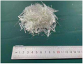 | 18 | 16 | 1.125 | 600 | 45 | 2.70 |
| Steel Fiber | 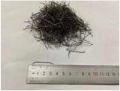 | 35 | 0.5 | 70.00 | 800 | 200 | 7.85 |
| Base Concrete | Compressive Strength (MPa) | Fine Aggregate (kg/m3) | Coarse Aggregate (kg/m3) | Cement (kg/m3) | Water (kg/m3) |
|---|---|---|---|---|---|
| C36 | 35.51 | 580.60 | 1281.40 | 434.20 | 128.80 |
| ID | Fiber | FVF (%) | Compressive Strength (MPa) | Compressive Failure and Crack Propagation | Tensile Strength (MPa) | Tensile Failure and Crack Propagation |
|---|---|---|---|---|---|---|
| GFRC-0 | None | 0 | 35.51 ± 0.78 | Conventional concrete exhibits fully and abruptly split along the crack without prior warning or visible indications. | 3.24 ± 0.10 | Conventional concrete forms sudden and complete splitting along the crack without visible indication. |
| GFRC-1 | Glass | 1.0 | 35.84 ± 1.65 | Glass fiber reinforced with insufficient fiber volume performs, to a large extent, similarly to conventional concrete. Glass fiber reinforced with sufficient fiber volume develops cracks progressively with gradual crushing, accompanied by reduced spalling. | 3.39 ± 0.14 | Glass fiber reinforced with insufficient fiber volume performs close to conventional concrete. Glass fiber reinforced with sufficient fiber volume eventually splits through cracks that develop progressively. |
| GFRC-2 | 2.0 | 36.65 ± 0.88 | 3.44 ± 0.14 | |||
| GFRC-3 | 3.0 | 38.76 ± 1.28 | 3.67 ± 0.13 | |||
| SFRC-0 | Steel | 0.75 | 40.03 ± 1.08 | Steel-fiber-reinforced concrete forms cracks more gradually, maintaining structural integrity without shattering. | 5.16 ± 0.26 | Steel-fiber-reinforced concrete develops cracks slowly and subtly, ultimately preventing splitting and preserving structural integrity. |
| SFRC-1 | 1.5 | 40.60 ± 0.93 | 5.82 ± 0.23 | |||
| SFRC-2 | 2.0 | 48.60 ± 2.04 | 4.12 ± 0.08 | |||
| SFRC-3 | 3.0 | 37.98 ± 1.41 | 4.16 ± 0.11 |
| Target Slab ID | Fiber | FVF (%) | Reinforced Bars | Relevant Slab | Relevant FRC | Fiber | FVF (%) |
|---|---|---|---|---|---|---|---|
| GFRC-3-G | Glass | 3.0 | GFRP | GFRC-0-G | GFRC-0 | Glass | 0 |
| GFRC-3-G | GFRC-1 | 1 | |||||
| GFRC-3-S | 3.0 | Steel | GFRC-0-S | GFRC-2 | 2 | ||
| GFRC-3-S | GFRC-3 | 3 | |||||
| SFRC-3-N | Steel | 3.0 | None | SFRC-0-N | SFRC-0 | Steel | 0.75 |
| SFRC-1-N | SFRC-1 | 1.5 | |||||
| SFRC-2-N | SFRC-2 | 2.0 | |||||
| SFRC-3-N | SFRC-3 | 3.0 |
| Slab ID | Fiber | FVF/% | Bar | Fcr/kN | Fcr/F*cr | Fu/kN | Fu/F*u | Fcr/Fu | δcr/mm | δcr/δ*cr | δu/mm | δu/δ*u | δcr/δu |
|---|---|---|---|---|---|---|---|---|---|---|---|---|---|
| GFRC-0-G | Glass | 0 | GFRP | 30.07 | 0.45 | 71.37 | 0.55 | 0.42 | 0.66 | 0.99 | 5.85 | 1.02 | 0.11 |
| GFRC-3-G | 3 | 36.52 | 0.54 | 83.70 | 0.64 | 0.44 | 0.77 | 1.15 | 5.49 | 0.96 | 0.14 | ||
| GFRC-0-S | 0 | Steel | 45.37 | 0.68 | 87.88 | 0.67 | 0.52 | 1.62 | 2.42 | 5.23 | 0.92 | 0.31 | |
| GFRC-3-S | 3 | 51.99 | 0.78 | 96.31 | 0.74 | 0.54 | 1.67 | 2.50 | 5.24 | 0.92 | 0.32 | ||
| SFRC-0-N | Steel | 0.75 | None | 64.22 | 0.96 | 96.07 | 0.74 | 0.67 | 0.59 | 0.88 | 2.25 | 0.39 | 0.26 |
| SFRC-1-N | 1.5 | 79.20 | 1.18 | 122.02 | 0.93 | 0.65 | 0.50 | 0.75 | 3.00 | 0.53 | 0.17 | ||
| SFRC-2-N | 2 | 76.86 | 1.15 | 120.35 | 0.92 | 0.64 | 0.45 | 0.67 | 3.76 | 0.66 | 0.12 | ||
| SFRC-3-N | 3 | 67.02 | 1 | 130.57 | 1 | 0.51 | 0.67 | 1 | 5.71 | 1 | 0.12 |
| Slab ID | Mn (kN · m) | Mu (kN · m) | ACI 440.1R [20] | JSCE 1997 [21] | Φ | cf (%) | ||
|---|---|---|---|---|---|---|---|---|
| Φtheo1 | Mutheo1 (kN · m) | Φtheo2 | Mutheo2 (kN · m) | |||||
| GFRC-0-G | 8.606 | 4.475 | 0.65 | 5.594 | 0.77 | 6.627 | 0.52 | - |
| GFRC-3-G | 8.871 | 5.234 | 0.65 | 5.766 | 0.77 | 6.861 | 0.59 | 16.96 |
| GFRC-0-S | 5.756 | 5.641 | 0.9 | 5.180 | 0.9 | 5.180 | 0.98 | - |
| GFRC-3-S | 5.775 | 6.006 | 0.9 | 5.198 | 0.9 | 5.198 | 1.04 | 6.47 |
| ID | Bearing Capacity/kN | Ductility /μ | Toughness/kN · mm | Bending Capacity | Energy Absorption | Crack Resistance | Corrosion Resistance | Structural Ductility | Safety Warning | |
|---|---|---|---|---|---|---|---|---|---|---|
| Crack | Ultimate | |||||||||
| GFRC-0-G | 30.07 | 71.37 | 2.57 | 310.40 | ||||||
| GFRC-3-G | 36.52 | 83.70 | 4.80 | 332.75 | √ | √ | √ | √ | √ | √ |
| GFRC-0-S | 45.37 | 87.88 | 1.44 | 292.80 | ||||||
| GFRC-3-S | 51.99 | 96.31 | 3.55 | 330.69 | √ | √ | √ | √ | √ | |
| SFRC-0-N | 64.22 | 96.07 | 1.65 | 153.05 | ||||||
| SFRC-1-N | 79.20 | 122.02 | 2.50 | 291.56 | ||||||
| SFRC-2-N | 76.86 | 120.35 | 3.25 | 344.99 | ||||||
| SFRC-3-N | 67.02 | 130.57 | 5.05 | 565.57 | √ | √ | √ | √ | √ | |
Disclaimer/Publisher’s Note: The statements, opinions and data contained in all publications are solely those of the individual author(s) and contributor(s) and not of MDPI and/or the editor(s). MDPI and/or the editor(s) disclaim responsibility for any injury to people or property resulting from any ideas, methods, instructions or products referred to in the content. |
© 2025 by the authors. Licensee MDPI, Basel, Switzerland. This article is an open access article distributed under the terms and conditions of the Creative Commons Attribution (CC BY) license (https://creativecommons.org/licenses/by/4.0/).
Share and Cite
Xie, F.; Tian, W.; Li, S.; Diez, P.; Zlotnik, S.; Gonzalez, A.G. Experimental Study on the Structural Performance of Glass-Fiber-Reinforced Concrete Slabs Reinforced with Glass-Fiber-Reinforced Polymer (GFRP) Bars: A Sustainable Alternative to Steel in Challenging Environments. Polymers 2025, 17, 1068. https://doi.org/10.3390/polym17081068
Xie F, Tian W, Li S, Diez P, Zlotnik S, Gonzalez AG. Experimental Study on the Structural Performance of Glass-Fiber-Reinforced Concrete Slabs Reinforced with Glass-Fiber-Reinforced Polymer (GFRP) Bars: A Sustainable Alternative to Steel in Challenging Environments. Polymers. 2025; 17(8):1068. https://doi.org/10.3390/polym17081068
Chicago/Turabian StyleXie, Fang, Wanming Tian, Shaofan Li, Pedro Diez, Sergio Zlotnik, and Alberto Garcia Gonzalez. 2025. "Experimental Study on the Structural Performance of Glass-Fiber-Reinforced Concrete Slabs Reinforced with Glass-Fiber-Reinforced Polymer (GFRP) Bars: A Sustainable Alternative to Steel in Challenging Environments" Polymers 17, no. 8: 1068. https://doi.org/10.3390/polym17081068
APA StyleXie, F., Tian, W., Li, S., Diez, P., Zlotnik, S., & Gonzalez, A. G. (2025). Experimental Study on the Structural Performance of Glass-Fiber-Reinforced Concrete Slabs Reinforced with Glass-Fiber-Reinforced Polymer (GFRP) Bars: A Sustainable Alternative to Steel in Challenging Environments. Polymers, 17(8), 1068. https://doi.org/10.3390/polym17081068