
Enhanced Mechanical Properties of 3D-Printed Glass Fibre-Reinforced Polyethylene Composites

 ,
,  , ,
, , 
Abstract
1. Introduction
2. Materials and Methods
2.1. Materials
2.2. Synthesis of Composite Materials
2.3. Testing Methods
2.4. Plasma Treatment
2.5. Printing of the Synthesised Composites
3. Results and Discussion
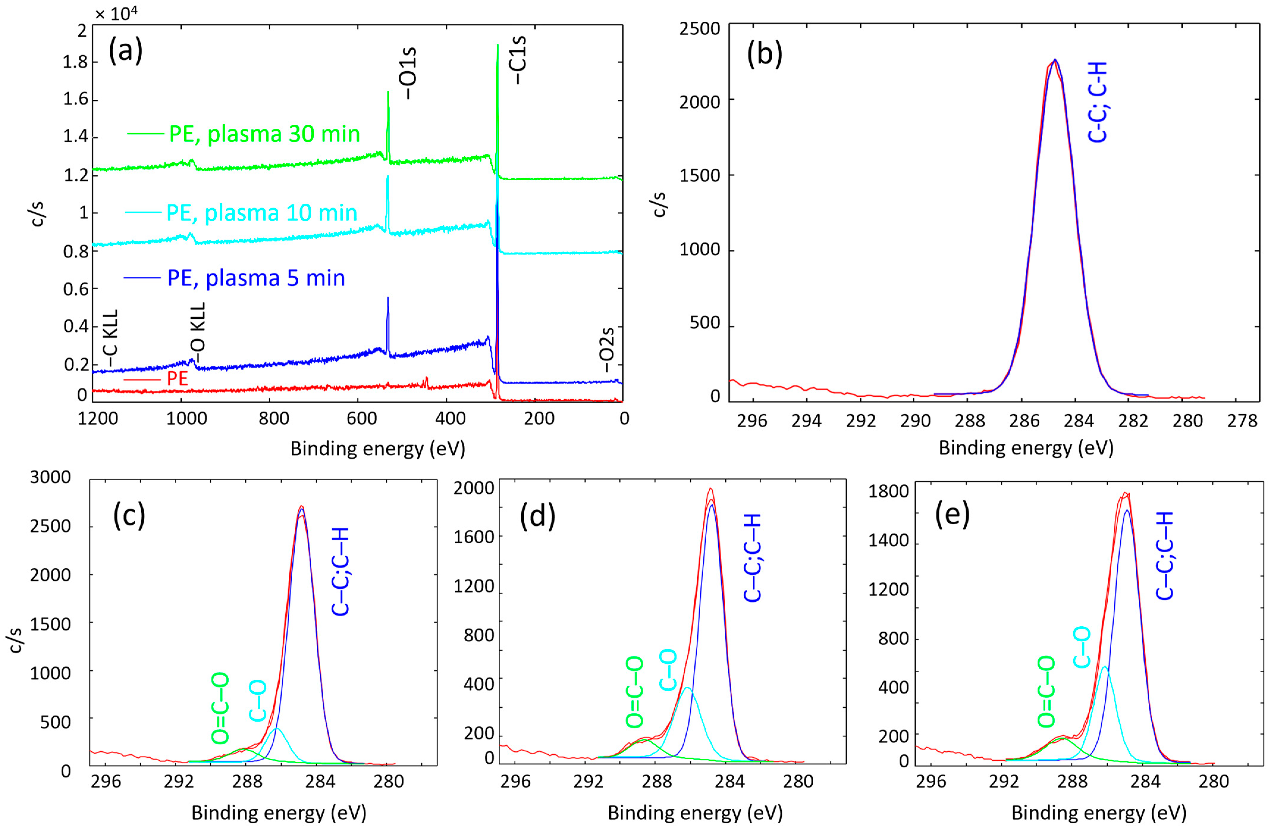
3.1. XPS Analysis
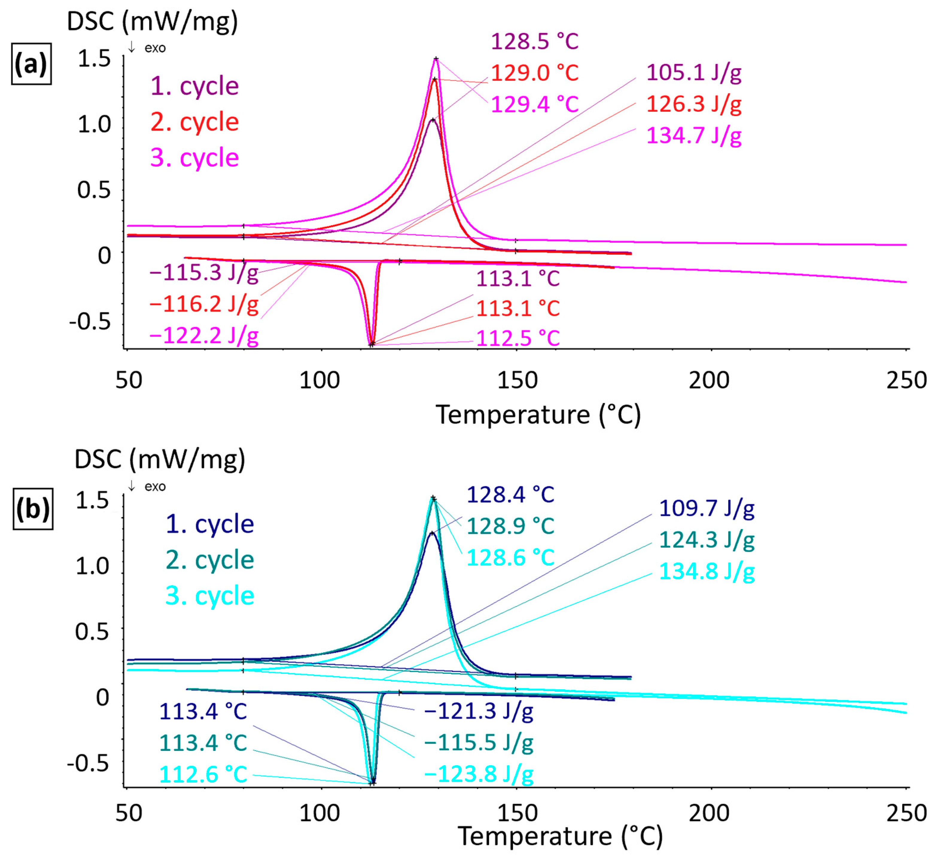
3.2. DSC Analysis
3.3. Filament Properties
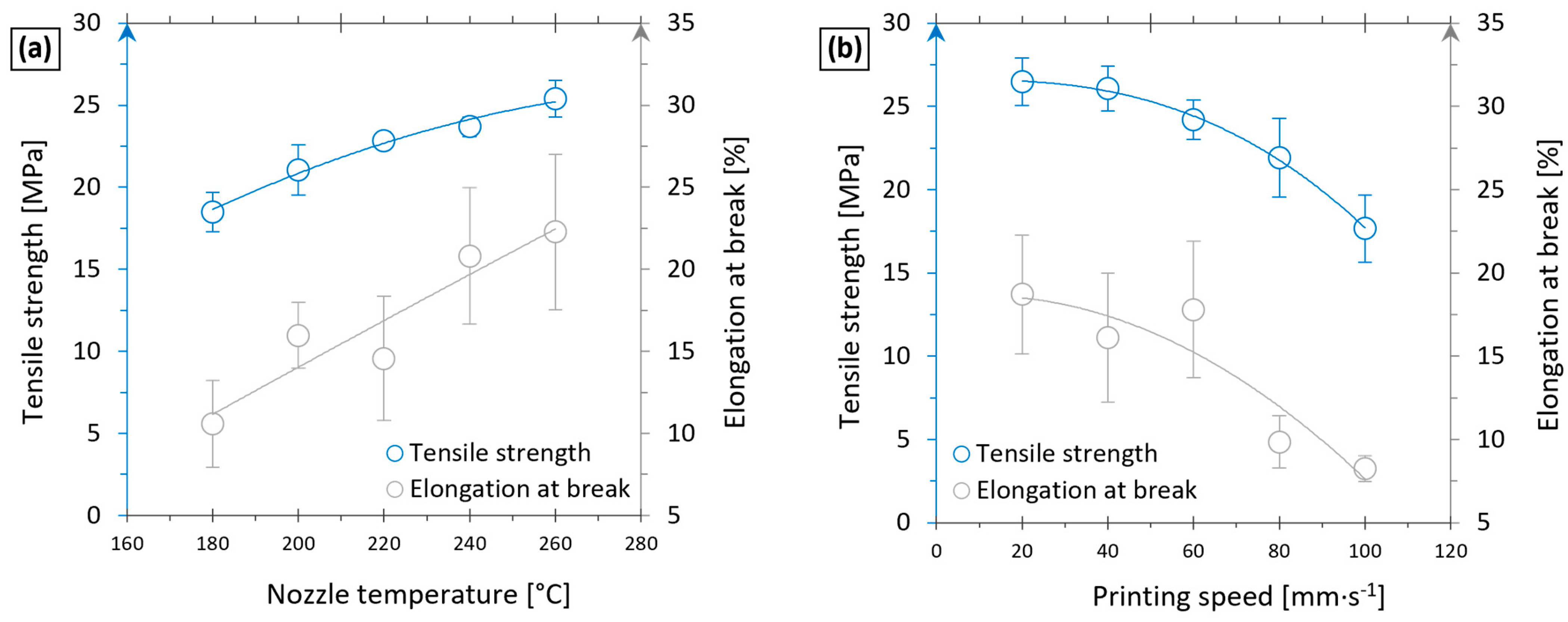
3.4. Optimisation of Printing Parameters
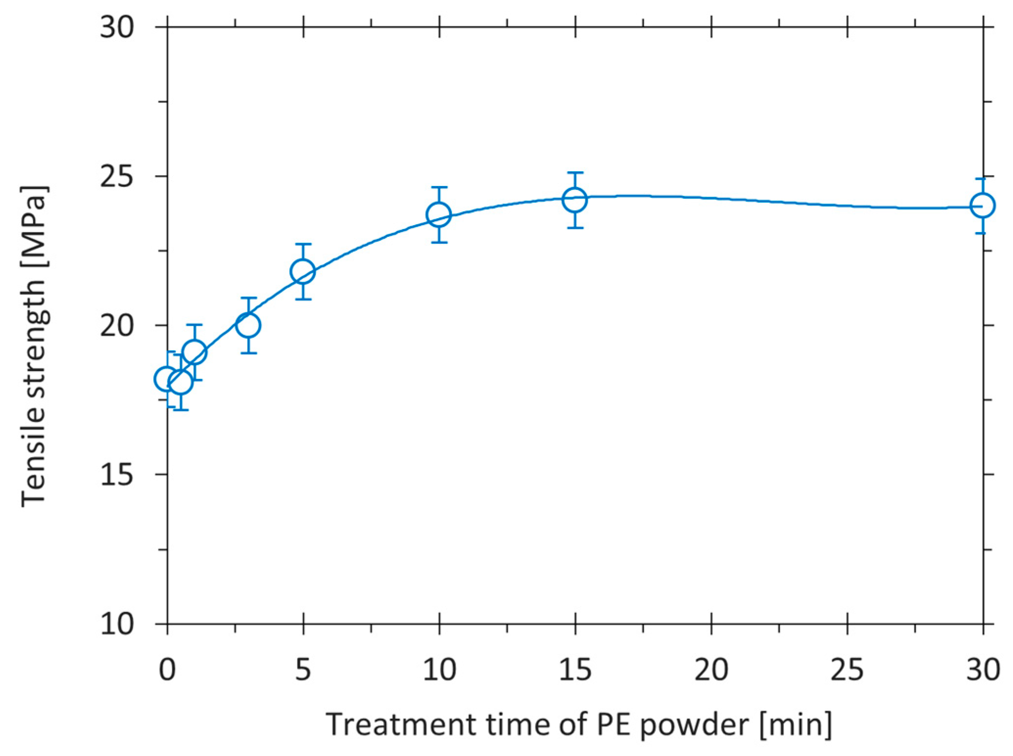
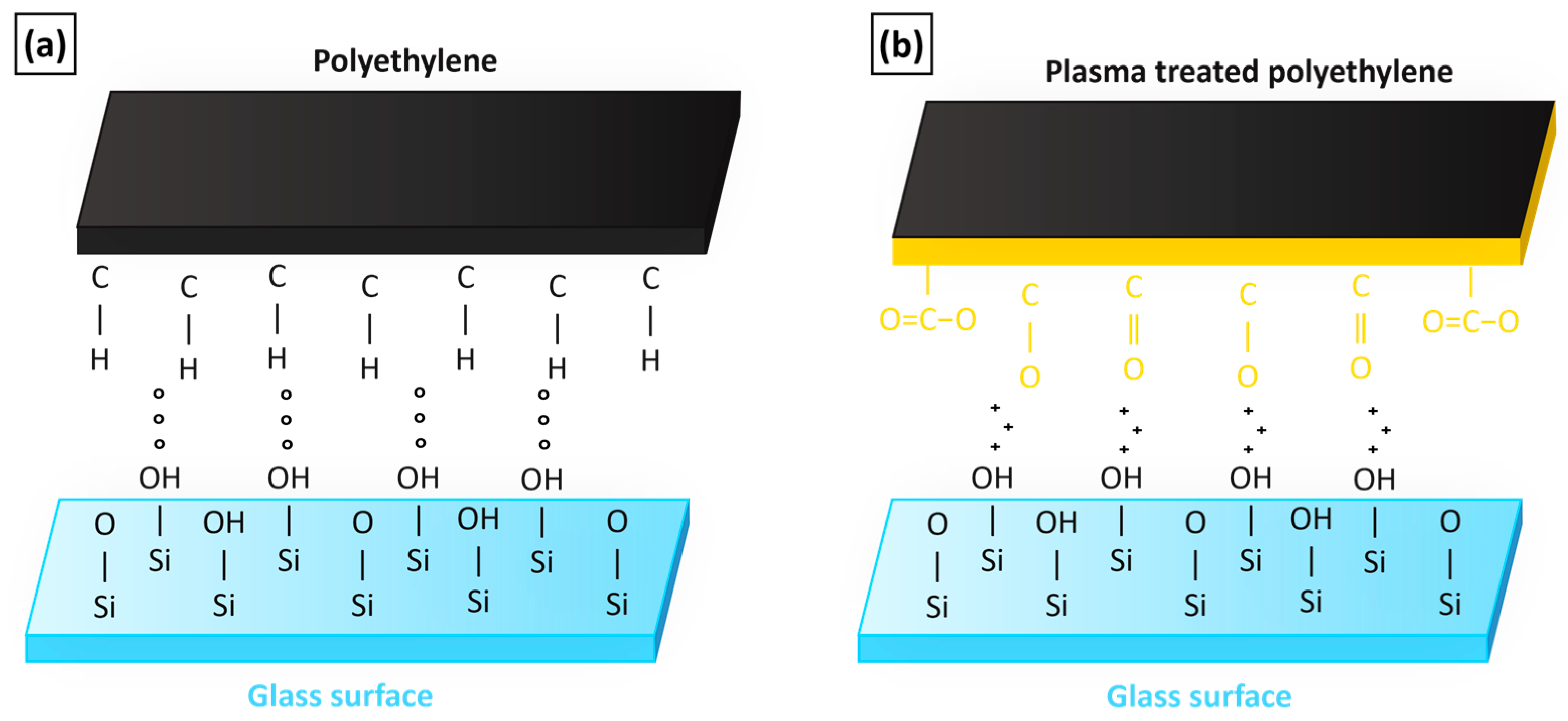
3.5. Effect of Matrix’s Plasma Treatment
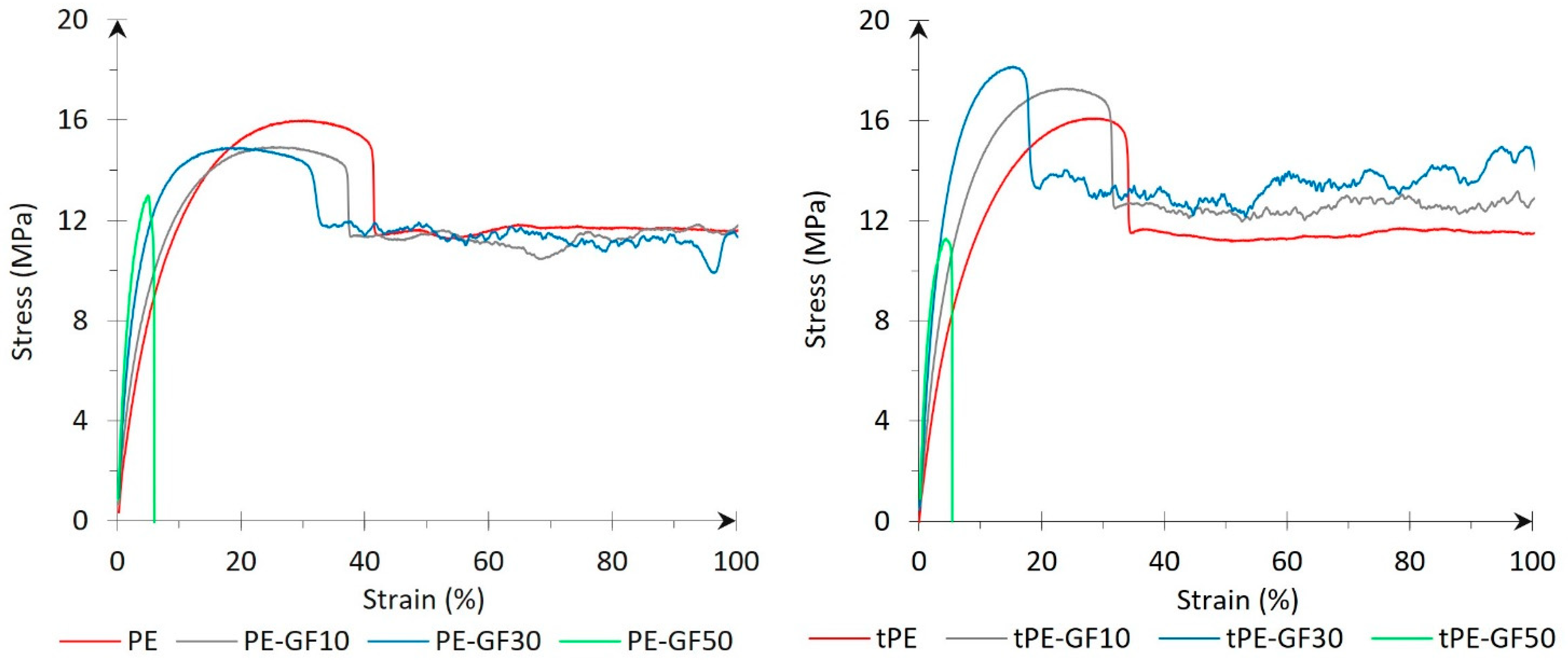
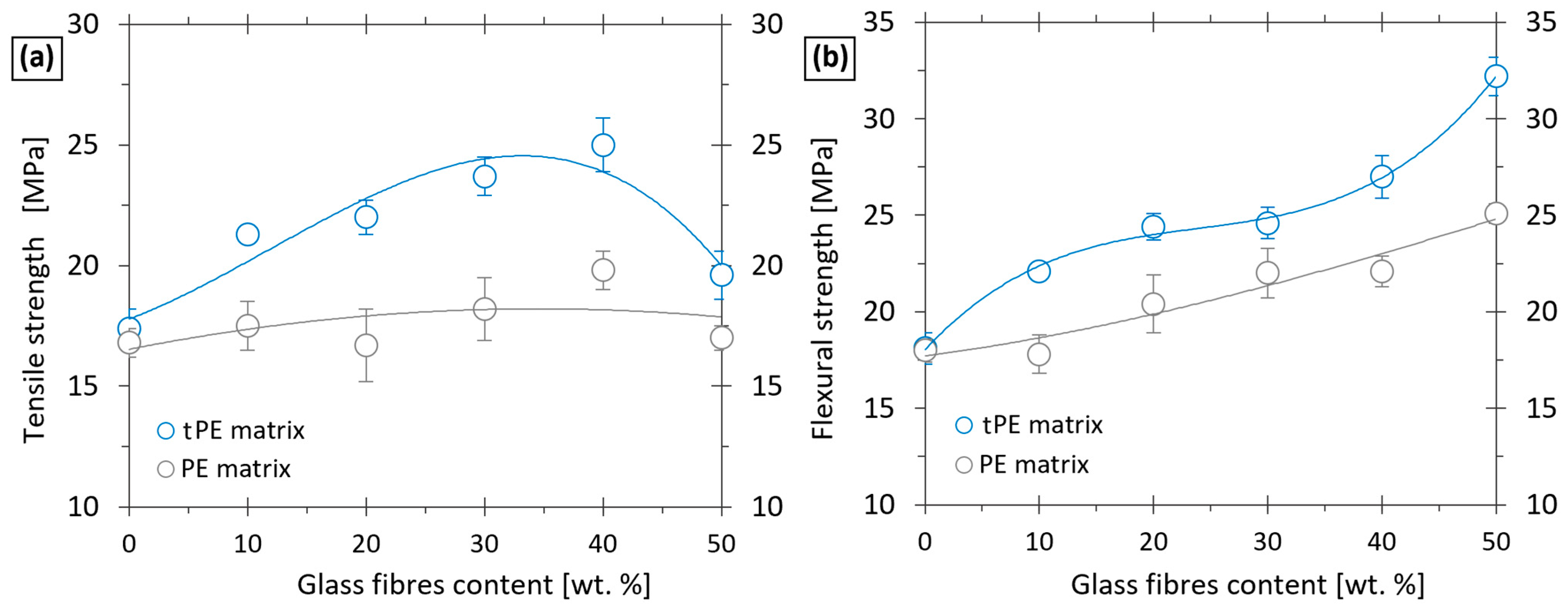
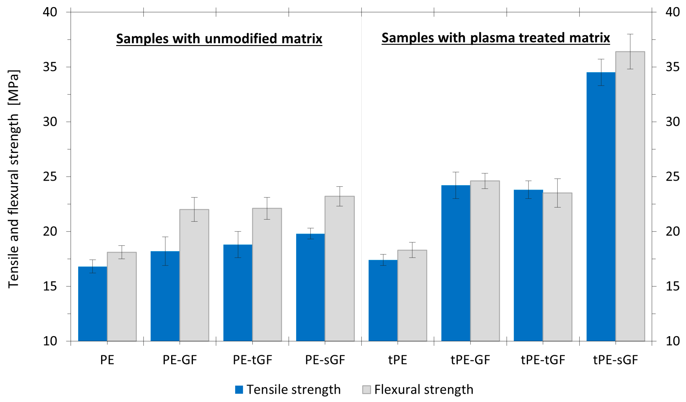
3.6. Influence of Fillers Modification on Mechanical Properties of Printed Composites
4. Conclusions
Author Contributions
Funding
Institutional Review Board Statement
Data Availability Statement
Conflicts of Interest
Abbreviations
| PE | Polyethylene |
| PP | Polypropylene |
| CF | Carbon fibres |
| CNT | Carbon nanotubes |
| GF | Unmodified glass fibres |
| tGF | Plasma-treated glass fibres |
| sGF | Glass fibres with silane sizing |
| tPE | Plasma-treated polyethylene |
| GFRPE | Glass-fibre-reinforced polyethylene composite |
| FDM | Fused deposition modelling |
| XPS | X-ray photoelectron spectroscopy |
| DSC | Differential scanning calorimetry |
| SEM | Scanning electron microscopy |
References
- Christakopoulos, F.; Van Heugten, P.M.H.; Tervoort, T.A. Additive Manufacturing of Polyolefins. Polymers 2022, 14, 5147. [Google Scholar] [CrossRef] [PubMed]
- Spoerk, M.; Holzer, C.; Gonzalez-Gutierrez, J. Material Extrusion-based Additive Manufacturing of Polypropylene: A Review on How to Improve Dimensional Inaccuracy and Warpage. J. Appl. Polym. Sci. 2020, 137, 48545. [Google Scholar] [CrossRef]
- Das, A.; Bryant, J.S.; Williams, C.B.; Bortner, M.J. Melt-Based Additive Manufacturing of Polyolefins Using Material Extrusion and Powder Bed Fusion. Polym. Rev. 2023, 63, 895–960. [Google Scholar] [CrossRef]
- Li, J.; Durandet, Y.; Huang, X.; Sun, G.; Ruan, D. Additively Manufactured Fiber-Reinforced Composites: A Review of Mechanical Behavior and Opportunities. J. Mater. Sci. Technol. 2022, 119, 219–244. [Google Scholar] [CrossRef]
- Carneiro, O.S.; Silva, A.F.; Gomes, R. Fused Deposition Modeling with Polypropylene. Mater. Des. 2015, 83, 768–776. [Google Scholar] [CrossRef]
- Sam-Daliri, O.; Ghabezi, P.; Steinbach, J.; Flanagan, T.; Finnegan, W.; Mitchell, S.; Harrison, N. Experimental Study on Mechanical Properties of Material Extrusion Additive Manufactured Parts from Recycled Glass Fibre-Reinforced Polypropylene Composite. Compos. Sci. Technol. 2023, 241, 110125. [Google Scholar] [CrossRef]
- Olesik, P.; Godzierz, M.; Kozioł, M. Preliminary Characterization of Novel LDPE-Based Wear-Resistant Composite Suitable for FDM 3D Printing. Materials 2019, 12, 2520. [Google Scholar] [CrossRef]
- Spoerk, M.; Arbeiter, F.; Raguž, I.; Weingrill, G.; Fischinger, T.; Traxler, G.; Schuschnigg, S.; Cardon, L.; Holzer, C. Polypropylene Filled with Glass Spheres in Extrusion-Based Additive Manufacturing: Effect of Filler Size and Printing Chamber Temperature. Macromol. Mater. Eng. 2018, 303, 1800179. [Google Scholar] [CrossRef]
- Spoerk, M.; Savandaiah, C.; Arbeiter, F.; Traxler, G.; Cardon, L.; Holzer, C.; Sapkota, J. Anisotropic Properties of Oriented Short Carbon Fibre Filled Polypropylene Parts Fabricated by Extrusion-Based Additive Manufacturing. Compos. Part A Appl. Sci. Manuf. 2018, 113, 95–104. [Google Scholar] [CrossRef]
- Casamento, F.; Padovano, E.; Pappalardo, S.; Frache, A.; Badini, C. Development of Polypropylene-Based Composites through Fused Filament Fabrication: The Effect of Carbon-Based Fillers. Compos. Part A Appl. Sci. Manuf. 2023, 164, 107308. [Google Scholar] [CrossRef]
- Beesetty, P.; Kale, A.; Patil, B.; Doddamani, M. Mechanical Behavior of Additively Manufactured Nanoclay/HDPE Nanocomposites. Compos. Struct. 2020, 247, 112442. [Google Scholar] [CrossRef]
- Bertolino, M.; Battegazzore, D.; Arrigo, R.; Frache, A. Designing 3D Printable Polypropylene: Material and Process Optimisation through Rheology. Addit. Manuf. 2021, 40, 101944. [Google Scholar] [CrossRef]
- Zander, N.E.; Park, J.H.; Boelter, Z.R.; Gillan, M.A. Recycled Cellulose Polypropylene Composite Feedstocks for Material Extrusion Additive Manufacturing. ACS Omega 2019, 4, 13879–13888. [Google Scholar] [CrossRef]
- Wang, L.; Palmer, J.; Tajvidi, M.; Gardner, D.J.; Han, Y. Thermal Properties of Spray-Dried Cellulose Nanofibril-Reinforced Polypropylene Composites from Extrusion-Based Additive Manufacturing. J. Therm. Anal. Calorim. 2019, 136, 1069–1077. [Google Scholar] [CrossRef]
- Milosevic, M.; Stoof, D.; Pickering, K. Characterizing the Mechanical Properties of Fused Deposition Modelling Natural Fiber Recycled Polypropylene Composites. J. Compos. Sci. 2017, 1, 7. [Google Scholar] [CrossRef]
- Filgueira, D.; Holmen, S.; Melbø, J.; Moldes, D.; Echtermeyer, A.; Chinga-Carrasco, G. 3D Printable Filaments Made of Biobased Polyethylene Biocomposites. Polymers 2018, 10, 314. [Google Scholar] [CrossRef]
- Tarrés, Q.; Melbø, J.K.; Delgado-Aguilar, M.; Espinach, F.X.; Mutjé, P.; Chinga-Carrasco, G. Bio-Polyethylene Reinforced with Thermomechanical Pulp Fibers: Mechanical and Micromechanical Characterization and Its Application in 3D-Printing by Fused Deposition Modelling. Compos. Part B Eng. 2018, 153, 70–77. [Google Scholar] [CrossRef]
- Stoof, D.; Pickering, K. Sustainable Composite Fused Deposition Modelling Filament Using Recycled Pre-Consumer Polypropylene. Compos. Part B Eng. 2018, 135, 110–118. [Google Scholar] [CrossRef]
- McGauran, T.; Dunne, N.; Smyth, B.M.; Cunningham, E. Incorporation of Poultry Eggshell and Litter Ash as High Loading Polymer Fillers in Polypropylene. Compos. Part C Open Access 2020, 3, 100080. [Google Scholar] [CrossRef]
- McGauran, T.; Harris, M.; Dunne, N.; Smyth, B.M.; Cunningham, E. Development and Optimisation of Extruded Bio-Based Polymers from Poultry Feathers. Eur. Polym. J. 2021, 158, 110678. [Google Scholar] [CrossRef]
- Vesel, A.; Primc, G.; Zaplotnik, R.; Mozetič, M. Applications of Highly Non-Equilibrium Low-Pressure Oxygen Plasma for Treatment of Polymers and Polymer Composites on an Industrial Scale. Plasma Phys. Control. Fusion 2020, 62, 024008. [Google Scholar] [CrossRef]
- Booth, J.-P.; Mozetič, M.; Nikiforov, A.; Oehr, C. Foundations of Plasma Surface Functionalization of Polymers for Industrial and Biological Applications. Plasma Sources Sci. Technol. 2022, 31, 103001. [Google Scholar] [CrossRef]
- Primc, G. Generation of Neutral Chemically Reactive Species in Low-Pressure Plasma. Front. Phys. 2022, 10, 895264. [Google Scholar] [CrossRef]
- Popović, D.; Mozetič, M.; Vesel, A.; Primc, G.; Zaplotnik, R. Review on Vacuum Ultraviolet Generation in Low-pressure Plasmas. Plasma Process. Polym. 2021, 18, 2100061. [Google Scholar] [CrossRef]
- Lojen, D.; Zaplotnik, R.; Primc, G.; Mozetič, M.; Vesel, A. Optimization of Surface Wettability of Polytetrafluoroethylene (PTFE) by Precise Dosing of Oxygen Atoms. Appl. Surf. Sci. 2022, 598, 153817. [Google Scholar] [CrossRef]
- Vesel, A.; Zaplotnik, R.; Mozetič, M.; Primc, G. Surface Modification of PS Polymer by Oxygen-Atom Treatment from Remote Plasma: Initial Kinetics of Functional Groups Formation. Appl. Surf. Sci. 2021, 561, 150058. [Google Scholar] [CrossRef]
- Píchal, J.; Hladík, J.; Špatenka, P. Atmospheric-Air Plasma Surface Modification of Polyethylene Powder. Plasma Process. Polym. 2009, 6, 148–153. [Google Scholar] [CrossRef]
- Vandencasteele, N.; Reniers, F. Plasma-Modified Polymer Surfaces: Characterization Using XPS. J. Electron Spectrosc. Relat. Phenom. 2010, 178–179, 394–408. [Google Scholar] [CrossRef]
- Mozetič, M. Aging of Plasma-Activated Polyethylene and Hydrophobic Recovery of Polyethylene Polymers. Polymers 2023, 15, 4668. [Google Scholar] [CrossRef]
- Liu, Z.; Tang, C.; Chen, P.; Yu, Q.; Li, W. Modification of Carbon Fiber by Air Plasma and Its Adhesion with BMI Resin. RSC Adv. 2014, 4, 26881. [Google Scholar] [CrossRef]
- Lee, H.S.; Kim, S.; Noh, Y.J.; Kim, S.Y. Design of Microwave Plasma and Enhanced Mechanical Properties of Thermoplastic Composites Reinforced with Microwave Plasma-Treated Carbon Fiber Fabric. Compos. Part B Eng. 2014, 60, 621–626. [Google Scholar] [CrossRef]
- Lee, Y.M.; You, J.; Kim, M.; Kim, T.A.; Lee, S.-S.; Bang, J.; Park, J.H. Highly Improved Interfacial Affinity in Carbon Fiber-Reinforced Polymer Composites via Oxygen and Nitrogen Plasma-Assisted Mechanochemistry. Compos. Part B Eng. 2019, 165, 725–732. [Google Scholar] [CrossRef]
- Zaldivar, R.J.; Kim, H.I.; Steckel, G.L.; Nokes, J.P.; Morgan, B.A. Effect of Processing Parameter Changes on the Adhesion of Plasma-Treated Carbon Fiber Reinforced Epoxy Composites. J. Compos. Mater. 2010, 44, 1435–1453. [Google Scholar] [CrossRef]
- Ma, K.; Chen, P.; Wang, B.; Cui, G.; Xu, X. A Study of the Effect of Oxygen Plasma Treatment on the Interfacial Properties of Carbon Fiber/Epoxy Composites. J. Appl. Polym. Sci. 2010, 118, 1606–1614. [Google Scholar] [CrossRef]
- Baghery Borooj, M.; Mousavi Shoushtari, A.; Haji, A.; Nosratian Sabet, E. Optimization of Plasma Treatment Variables for the Improvement of Carbon Fibres/Epoxy Composite Performance by Response Surface Methodology. Compos. Sci. Technol. 2016, 128, 215–221. [Google Scholar] [CrossRef]
- Yoozbashizadeh, M.; Chartosias, M.; Victorino, C.; Decker, D. Investigation on the Effect of Process Parameters in Atmospheric Pressure Plasma Treatment on Carbon Fiber Reinforced Polymer Surfaces for Bonding. Mater. Manuf. Process. 2019, 34, 660–669. [Google Scholar] [CrossRef]
- Dighton, C.; Rezai, A.; Ogin, S.L.; Watts, J.F. Atmospheric Plasma Treatment of CFRP Composites to Enhance Structural Bonding Investigated Using Surface Analytical Techniques. Int. J. Adhes. Adhes. 2019, 91, 142–149. [Google Scholar] [CrossRef]
- Yildirim, C.; Ulus, H.; Beylergil, B.; Al-Nadhari, A.; Topal, S.; Yildiz, M. Effect of Atmospheric Plasma Treatment on Mode-I and Mode-II Fracture Toughness Properties of Adhesively Bonded Carbon Fiber/PEKK Composite Joints. Eng. Fract. Mech. 2023, 289, 109463. [Google Scholar] [CrossRef]
- Yuan, X.; Jayaraman, K.; Bhattacharyya, D. Effects of Plasma Treatment in Enhancing the Performance of Woodfibre-Polypropylene Composites. Compos. Part A Appl. Sci. Manuf. 2004, 35, 1363–1374. [Google Scholar] [CrossRef]
- Han, S.H.; Oh, H.J.; Kim, S.S. Evaluation of Fiber Surface Treatment on the Interfacial Behavior of Carbon Fiber-Reinforced Polypropylene Composites. Compos. Part B Eng. 2014, 60, 98–105. [Google Scholar] [CrossRef]
- Xie, J.; Xin, D.; Cao, H.; Wang, C.; Zhao, Y.; Yao, L.; Ji, F.; Qiu, Y. Improving Carbon Fiber Adhesion to Polyimide with Atmospheric Pressure Plasma Treatment. Surf. Coat. Technol. 2011, 206, 191–201. [Google Scholar] [CrossRef]
- Corral, F.S.; Nava, L.A.C.; Hernández, E.H.; Gámez, J.F.H.; Velázquez, M.G.N.; Sierra, M.I.M.; Morones, P.G.; Gómez, R.E.D.D.L. Plasma Treatment of Agave Fiber Powder and Its Effect on the Mechanical and Thermal Properties of Composites Based on Polyethylene. Int. J. Polym. Sci. 2016, 2016, 1–7. [Google Scholar] [CrossRef]
- Couto, E.; Tan, I.H.; Demarquette, N.; Caraschi, J.C.; Leão, A. Oxygen Plasma Treatment of Sisal Fibers and Polypropylene: Effects on Mechanical Properties of Composites. Polym. Eng. Sci. 2002, 42, 790–797. [Google Scholar] [CrossRef]
- Anjumol, K.S.; Sumesh, K.R.; Vackova, T.; Hanna, J.M.; Thomas, S.; Spatenka, P. Effect of Plasma Treatment on the Morphology, Mechanical, and Wetting Properties of Polyethylene/Banana Fiber Composites. Biomass Conv. Bioref. 2024, 14, 30239–30250. [Google Scholar] [CrossRef]
- Sari, P.S.; Thomas, S.; Spatenka, P.; Ghanam, Z.; Jenikova, Z. Effect of Plasma Modification of Polyethylene on Natural Fibre Composites Prepared via Rotational Moulding. Compos. Part B Eng. 2019, 177, 107344. [Google Scholar] [CrossRef]
- Sumesh, K.R.; Ghanem, Z.; Spatenka, P.; Jenikova, Z. Investigating the Influence of Plasma Treated Polyethylene Powder, Carbon Fibers in Enhancing the Mechanical Properties of Polymer Composites Using Rotomoulding Method. Polym. Compos. 2023, 44, 1004–1016. [Google Scholar] [CrossRef]
- ASTM D638; Standard Test Method for Tensile Properties of Plastics. ASTM International: West Conshohocken, PA, USA, 2022.
- ASTM D790; Standard Test Methods for Flexural Properties of Unreinforced and Reinforced Plastics and Electrical Insulating Materials. ASTM International: West Conshohocken, PA, USA, 2017.
- Šourková, H.; Primc, G.; Špatenka, P. Surface Functionalization of Polyethylene Granules by Treatment with Low-Pressure Air Plasma. Materials 2018, 11, 885. [Google Scholar] [CrossRef] [PubMed]
- Paul, D.; Mozetic, M.; Zaplotnik, R.; Primc, G.; Đonlagić, D.; Vesel, A. A Review of Recombination Coefficients of Neutral Oxygen Atoms for Various Materials. Materials 2023, 16, 1774. [Google Scholar] [CrossRef]
- Zhang, Y.; Ishikawa, K.; Mozetič, M.; Tsutsumi, T.; Kondo, H.; Sekine, M.; Hori, M. Polyethylene Terephthalate (PET) Surface Modification by VUV and Neutral Active Species in Remote Oxygen or Hydrogen Plasmas. Plasma Process. Polym. 2019, 16, 1800175. [Google Scholar] [CrossRef]
- Verma, N.; Awasthi, P.; Gupta, A.; Banerjee, S.S. Fused Deposition Modeling of Polyolefins: Challenges and Opportunities. Macromol. Mater. Eng. 2023, 308, 2200421. [Google Scholar] [CrossRef]
- Jeyachandran, P.; Bontha, S.; Bodhak, S.; Balla, V.K.; Doddamani, M. Material Extrusion Additive Manufacturing of Bioactive Glass/High Density Polyethylene Composites. Compos. Sci. Technol. 2021, 213, 108966. [Google Scholar] [CrossRef]
- Bell, C.A. Maintaining and Troubleshooting Your 3D Printer: Properly Maintain and Enhance Your Investment in Personal Fabrication; Technology in Action; Apress: Berkeley, CA, USA, 2014; ISBN 978-1-4302-6808-6. [Google Scholar]
- Gilmer, E.L.; Miller, D.; Chatham, C.A.; Zawaski, C.; Fallon, J.J.; Pekkanen, A.; Long, T.E.; Williams, C.B.; Bortner, M.J. Model Analysis of Feedstock Behavior in Fused Filament Fabrication: Enabling Rapid Materials Screening. Polymer 2018, 152, 51–61. [Google Scholar] [CrossRef]
- Šourková, H.; Špatenka, P. Plasma Activation of Polyethylene Powder. Polymers 2020, 12, 2099. [Google Scholar] [CrossRef] [PubMed]
- Cech, V.; Prikryl, R.; Balkova, R.; Grycova, A.; Vanek, J. Plasma Surface Treatment and Modification of Glass Fibers. Compos. Part A Appl. Sci. Manuf. 2002, 33, 1367–1372. [Google Scholar] [CrossRef]
- Dul, S.; Fambri, L.; Pegoretti, A. High-Performance Polyamide/Carbon Fiber Composites for Fused Filament Fabrication: Mechanical and Functional Performances. J. Mater. Eng. Perform. 2021, 30, 5066–5085. [Google Scholar] [CrossRef]
- Li, X.; He, J.; Hu, Z.; Ye, X.; Wang, S.; Zhao, Y.; Wang, B.; Ou, Y.; Zhang, J. High Strength Carbon-Fiber Reinforced Polyamide 6 Composites Additively Manufactured by Screw-Based Extrusion. Compos. Sci. Technol. 2022, 229, 109707. [Google Scholar] [CrossRef]
- Kim, D.-K.; Han, W.; Kim, K.-W.; Kim, B.-J. Enhanced Interfacial Properties of Carbon Fiber/Maleic Anhydride-Grafted Polypropylene Composites via Two-Step Surface Treatment: Electrochemical Oxidation and Silane Treatment. Polymers 2023, 15, 3784. [Google Scholar] [CrossRef]
- Weberová, Z.; Šourková, H.; Antoň, J.; Vacková, T.; Špatenka, P. New Method for Optimization of Polymer Powder Plasma Treatment for Composite Materials. Polymers 2021, 13, 965. [Google Scholar] [CrossRef]


| Variable Parameters | Constant Parameters | ||
|---|---|---|---|
| Nozzle temperature | 180–260 °C | Bed temperature | 90 °C |
| Printing speed | 20–100 mm∙s−1 | Nozzle diameter | 0.8 mm |
| GF content | 0–50 wt.% | Thickness of the 1st layer | 0.4 mm |
| Matrix modification | Neat PE vs. Plasma-treated PE (tPE; O2; 10 min; 300 sccm, 100 Pa) | Layer thickness | 0.25 mm |
| Treatment time in plasma | 0.5–30 min | Infill orientation | Longitudinal (0°) |
| Infill density | 100% | ||
| Carbon Bonds [at. %] | C-C, C-H | C-O | O=C-O |
|---|---|---|---|
| PE-untreated | 100 | 0 | 0 |
| tPE–(5 min) | 85.1 | 9.6 | 5.3 |
| tPE–(10 min) | 69.8 | 23.9 | 6.3 |
| tPE–(30 min) | 68.0 | 23.3 | 8.7 |
Disclaimer/Publisher’s Note: The statements, opinions and data contained in all publications are solely those of the individual author(s) and contributor(s) and not of MDPI and/or the editor(s). MDPI and/or the editor(s) disclaim responsibility for any injury to people or property resulting from any ideas, methods, instructions or products referred to in the content. |
© 2025 by the authors. Licensee MDPI, Basel, Switzerland. This article is an open access article distributed under the terms and conditions of the Creative Commons Attribution (CC BY) license (https://creativecommons.org/licenses/by/4.0/).
Share and Cite
Sezemský, J.; Primc, G.; Vacková, T.; Jeníková, Z.; Mozetič, M.; Špatenka, P. Enhanced Mechanical Properties of 3D-Printed Glass Fibre-Reinforced Polyethylene Composites. Polymers 2025, 17, 1154. https://doi.org/10.3390/polym17091154
Sezemský J, Primc G, Vacková T, Jeníková Z, Mozetič M, Špatenka P. Enhanced Mechanical Properties of 3D-Printed Glass Fibre-Reinforced Polyethylene Composites. Polymers. 2025; 17(9):1154. https://doi.org/10.3390/polym17091154
Chicago/Turabian StyleSezemský, Jan, Gregor Primc, Taťana Vacková, Zdeňka Jeníková, Miran Mozetič, and Petr Špatenka. 2025. "Enhanced Mechanical Properties of 3D-Printed Glass Fibre-Reinforced Polyethylene Composites" Polymers 17, no. 9: 1154. https://doi.org/10.3390/polym17091154
APA StyleSezemský, J., Primc, G., Vacková, T., Jeníková, Z., Mozetič, M., & Špatenka, P. (2025). Enhanced Mechanical Properties of 3D-Printed Glass Fibre-Reinforced Polyethylene Composites. Polymers, 17(9), 1154. https://doi.org/10.3390/polym17091154