Article

Enhancing CO2 Injection Efficiency: Rock-Breaking Characteristics of Particle Jet Impact in Bottom Hole

1
Key Laboratory of Ultra-Deep Drilling Engineering Technology, SINOPEC, Beijing 102200, China
2
SINOPEC Research Institute of Petroleum Engineering, Co., Ltd., Beijing 102200, China
3
Dongying Academy of Science and Technology, China University of Petroleum (East China), Dongying 257061, China
4
School of Petroleum Engineering, China University of Petroleum (East China), Qingdao 266580, China
*
Author to whom correspondence should be addressed.
Atmosphere 2024, 15(6), 645; https://doi.org/10.3390/atmos15060645
Submission received: 10 April 2024 / Revised: 14 May 2024 / Accepted: 26 May 2024 / Published: 28 May 2024
(This article belongs to the Special Issue CO2 Geological Storage and Utilization (2nd Edition))

Abstract

:
Storing CO2 in oil and gas reservoirs offers a dual benefit: it reduces atmospheric CO2 concentration while simultaneously enhancing oil displacement efficiency and increasing crude oil production. This is achieved by injecting CO2 into producing oil and gas wells. Employing particle jet technology at the bottom of CO2 injection wells significantly expands the bottom hole diameter, thereby improving CO2 injection efficiency and storage safety. To further investigate the rock-breaking characteristics and efficiency, a finite element model for particle jet rock breaking is established by utilizing the smoothed particle hydrodynamics (SPH) method. Specifically, this new model considers the high temperature and confining pressure conditions present at the bottom hole. The dynamic response and fracturing effects of rock subjected to a particle jet are also revealed. The results indicate that particle jet impact rebound significantly influences the size of the impact crater, with the maximum first principal stress primarily concentrated on the crater’s surface. The impact creates a “v”-shaped crater on the rock surface, with both depth and volume increasing proportionally to jet inlet velocity and particle diameter. However, beyond a key particle concentration of 3%, the increase in depth and volume becomes less pronounced. Confining pressure is found to hinder particle impact rock-breaking efficiency, while high temperatures contribute to larger impact depths and breaking volumes. This research can provide theoretical support and parameter guidance for the practical application of particle impact technology in enhancing CO2 injection efficiency at the bottom hole.

1. Introduction

The current CO2 storage methods primarily encompass geological, marine, and chemical storage. Geological storage involves the injection of CO2 into various geological formations (typically at depths exceeding 800 m), where it is stored in a supercritical state [1]. This method offers the potential for permanent CO2 sequestration under certain conditions, such as good sealing ability. Theoretical research and practical applications have identified suitable geological formations for CO2 storage, including oil and gas reservoirs, deep saline aquifers, basalt rocks, and unrecoverable coal seams. Among these, oil and gas reservoirs present the lowest leakage risk due to their inherent sealing properties, as demonstrated by their ability to retain oil and gas over prolonged geological periods [2]. Additionally, the existing infrastructure of production and injection wells in these reservoirs makes CO2 storage more convenient and cost-effective. CO2 reservoir storage, achieved by injecting supercritical CO2 into oil and gas reservoirs through production wells, represents a permanent CO2 sequestration solution and a primary method for CO2 storage. Currently, this approach is primarily combined with enhanced oil recovery techniques [3]. In a similar manner to water flooding, CO2 injection drives oil towards production wells, thereby improving oil recovery. However, optimizing CO2 injection efficiency (CO2 injection amount per unit time) in these wells remains crucial. Bottom hole reaming, a technique that expands the bottom hole diameter, increases the CO2 injection and working area and leads to significant improvements in CO2 injection efficiency [4]. Particle impact technology has proven effective in enhancing the breaking efficiency of formation rocks [5,6]. This paper proposes a novel particle jet impact reaming technology that utilizes particle jets to impact the rock at the bottom of CO2 injection wells, thereby expanding the CO2 injection area and improving injection efficiency.
Particle jet impact has demonstrably enhanced the breaking and cutting efficiency of rocks and other materials [7,8,9]. This technology utilizes steel particle water jets, formed by introducing steel particles with diameters ranging from 1 to 3 mm into a water jet at concentrations of 0.5 to 3% by volume. The high density and large diameter of these steel particles significantly augment the impact energy, which leads to improved material-breaking efficiency [10,11]. In contrast to conventional abrasive jets that employ sand, this technology utilizes large-diameter spherical steel particles, which effectively amplify the jet’s erosion energy. Upon exiting the nozzle at high velocity, these particles impact the rock surface, generating instantaneous extreme stress and inducing tensile and shear cracks within the rock [12]. The continuous particle impact propagates and connects these cracks, resulting in greater volume fragmentation of the rock and significantly improving the efficiency of the jet’s rock-breaking energy. Moreover, the spherical shape of steel particles effectively minimizes erosion wear on pipelines and other equipment [13].
Numerous factors influence the rock-breaking efficacy of particle impact, including particle velocity, concentration, diameter, and pressure [14,15]. When particles are accelerated by the water jet and impact the rock surface at high speed, the rock-breaking efficiency is significantly improved [16,17,18]. High-speed particle impact causes material damage in two ways: stripping damage to the surface and impact damage to the material’s interior [19]. The impact generates substantial stress within a very short timeframe, leading to significant deformation damage [20,21]. In particle jet cutting, the cutting depth increases with jet velocity and decreases with standoff distance and moving speed, with standoff distance exerting the greatest influence on cutting volume [22]. Following the abrasive jet impact on the material surface, the abrasive interacts with the surface briefly, causing severe erosion wear [23]. This wear manifests primarily as intergranular fracture microscopic cracks and macroscopic lateral cracks induced by the abrasive particles [24,25,26]. The effects of different ice particle velocities (12.05 m/s to 74.33 m/s), particle diameters (1.86 mm to 2.83 mm), and temperatures (−35 °C to −5 °C) on the impact efficiency have been studied experimentally. When the ice particle velocity is greater than 50 m/s, there will be an accumulation of impact debris near the impact crater [27]. The characteristics of particle impact on the wall surface have been studied using the CFD-DEM coupling method. The effectiveness of the erosion model has been verified by experiments. When the particle impact angle is 15 to 30°, the erosion of the material is the largest [28]. Through the measurement and analysis of the rebound velocity and rebound angle of the particles, it is found that when the particle volume fraction is greater than or equal to 0.41%, a layer of particles will form near the surface of the impact crater [29]. The ultrasonic vibration field-induced, ultra-high-frequency particle impact rock-breaking technology can increase the impact stress by more than 10 times, reduce the rock-breaking time from a few minutes (2–3 min) to seconds (2–4 s), and increase the rock-breaking efficiency by nearly 10 times [30]. During the particle impact process, the smaller grains of the material are easily heated, and the propagation of cracks is hindered [31]. The impact process of non-spherical particles has been studied by numerical simulation of a DEM model. By considering three particle shapes, cube, cylinder, and oval, it was found that the particle shape has a great influence on the crushing form of the material [32]. Simulation studies using the SPH method have investigated particle impact penetration, revealing a positive correlation between penetration depth and particle velocity for a given particle diameter. A critical particle impact velocity exists, beyond which the penetration depth increases rapidly [33]. The SPH method has also been employed to study the dynamic process of conical teeth penetrating clay, resulting in a clay impact model that incorporates the friction angle [34]. Additionally, the SPH-FEM coupling method has been used to analyze the crushing process of aluminum tubes under quasi-static conditions [35].
As the preceding analysis reveals, the current research on jet rock breaking predominantly focuses on pure water jets or abrasive jets, with a limited investigation into the utilization of steel, spherical, and large-diameter particles for rock breaking [15,36]. Furthermore, the SPH-FEM method is primarily employed to analyze quasi-static material breakage, and previous studies have rarely considered the effects of bottom hole confining pressure and high temperature. To address this gap, this study establishes a theoretical model using the SPH method to analyze rock breaking by particle jets at the bottom hole of a CO2 injection well. The model investigates the influence of particle parameters, confining pressure, and temperature on rock-breaking efficiency, providing theoretical guidance for the application of this technology to enhance CO2 injection efficiency.

2. Methods

2.1. Finite Element Model

2.1.1. SPH-FEM Model

This study utilizes the SPH-FEM coupling method to investigate the rock-breaking process and mechanism associated with particle jet impact at the bottom hole of a CO2 injection well, and it analyzes the influence of particle jet parameters on rock-breaking efficiency. The particle jet is modeled using the SPH method, while the rock is modeled using the FEM method. The flow characteristics of particles and fluid can be better described by the SPH method, while the damage and breaking of rock can be better described by the FEM method [34,35].
The kernel estimated value f(x) can be expressed by using Equation (1) [37], as follows:
f x = Ω f x W x x , h d x
where f x is the function of the 3D coordinate vector x, Ω is the support domain of the point x, x x is the distance between the particles, h is the smooth length of the SPH particle changing along with time and space, and W x x , h is the kernel function, usually defined by the auxiliary function ( θ x x ):
W x x , h = 1 h x x d θ x x
where d is the dimension of the space.
The cubic b-spline curve is most commonly utilized for a smooth function in the SPH method, as described by the following equation:
θ u = C b 1 3 2 u 2 + 3 4 u 3 ,   u 1 1 4 2 u 3 ,   1 u 2 0 ,   u 2
where Cb is the normalization constant, confirmed by the space dimension u = x x h .
Substituting Equation (2) into Equation (1), and converting the continuous form integral equation into the discrete form equation, we have the following equation:
f ( x ) = i = 1 n m i ρ i 1 h ( x x ) d θ ( x x i )
where ρ i is the density of particle i and m i is the mass of particle i.

2.1.2. Water and Rock Damage Model

The 1# elastic material model in the ANSYS-DYNA was utilized for particles, and the parameters are listed in Table 1 [38].
The MAT_NULL material model was utilized for water. The GRUNEISEN state equation expressed by Equation (5) was also utilized for water, and the parameters are also listed in Table 2 [39]:
P MG = ρ 0 C MG 2 1 + 1 γ 0 2 μ a 2 μ 2 1 S 1 1 μ S 2 μ 2 μ + 1 S 3 μ 3 μ + 1 2 + γ 0 + a μ E a
where P MG is the pressure; E is the internal energy per unit volume; C MG is the intercept of the u s - u p curve; ρ 0 is the density; S1, S2, and S3 are the slope coefficients of the curve; γ 0 is the GRUNEISEN constant; and a is the volume correction.
The Holmquist–Johnson–Cook (HJC) model was utilized for the sandstone; it is usually employed as the rock damage model under high deformation, a high strain rate, and high pressure [40]. The yield surface equation of the HJC model is as follows:
σ * = [ A ( 1 D ) + B P * N ] ( 1 + C ln ε * )
where σ * is the dimensionless equivalent stress, and it can be obtained from the actual equivalent stress divided by the static compressive strength f C ; P * is the dimensionless hydrostatic pressure, and it can be obtained from the actual hydrostatic pressure divided by the static compressive strength f C ; and ε * is the dimensionless strain rate, and it can be obtained from the actual strain rate divided by the reference strain rate ε 0 . D is the damage ratio, A is the characteristic bonding strength parameter, B is the characteristic pressure hardening index, N is the pressure hardening index, and C is the strain rate effect coefficient.
The damage was described by the accumulation of the equivalent plastic and plastic volumetric strains. The damage evolution equation is represented by Equation (7) [41]:
D = Δ ε p + Δ μ p ε p f + μ p f
where Δ ε p and Δ μ p are the equivalent plastic and plastic volumetric strains, respectively, in an iteration, and ε p f and μ p f are the equivalent plastic strain and plastic volumetric strain, respectively, under the atmospheric pressure. The parameters of the HJC model for the rock during the simulation are listed in Table 3.

2.1.3. Finite Element Model Description

The ANSYS 18.2 software is utilized to conduct the numerical simulation of the rock breaking. Figure 1 illustrates the three-dimensional meshing model of rock breaking under particle jet impact, which consists of approximately 190,000 elements. The rock is discretized using SOLID 164 units, and particle concentration is controlled by specifying the number of steel particles within the SPH particle domain. The red particles in Figure 1 represent these steel particles. Rock penetration and breakage are simulated by removing finite element nodes. When the equivalent plastic strain surpasses the minimum value ε fmin = 0.01, the rock element nodes begin to be removed, which signifies the onset of damage and breakage. The NON-REFLECTING boundary is applied to the bottom and sides of the rock. The rock-breaking process with the particle jet can be simulated by the following two assumptions: (1) the jet fluid is pure water; (2) the rock is considered as a continuum medium.
Confining pressure and temperature are applied through the following steps: (1) Define the pressure load curve; (2) define the “Segment” set on the plane where confining pressure is to be applied; (3) apply the pressure load curve; (4) define interface springback. (5) apply temperature load; and (6) solve and output: solve the model and output the results as a *K file.

2.2. Experimental

2.2.1. Experimental Setup

Firstly, connect all the components of the experimental system. Then, start the high-pressure pump, which sucks the fluid from the water tank and pressurizes the fluid. The high-pressure pipe transmits the high-pressure fluid into the particle mixing chamber. The particles stored in the particle hopper are transported to the mixing chamber under the negative pressure effect of the mixing chamber. Then, the high-pressure fluid is mixed with the particles. Finally, the particle jet sprays from the nozzle to impact the rock. The diverter valve is used to control the fluid flow, the fluid pressure is measured by the pressure gauge, and the fluid flow is measured by the flowmeter. The experimental flow chart and setup are shown in Figure 2.

2.2.2. Materials

Spherical steel particles with a density of 7.8 g/mm3 are utilized to impact the rock. The rock is marble with a density of 2.8 g/mm3. The steel particles and rock sample used in the experiment are shown in Figure 3.

2.3. Theoretical Model Validation

The deviations between the simulation results and the experimental results are shown in Table 4. The crater depth and crater volume obtained by the experiment are slightly smaller than those obtained by the simulation. This may be due to factors such as uneven particle mixing in the experiment, which leads to the low experimental value. The deviations of the crater depth and crater volume obtained by simulation and experiment are 3.6% and 5%, respectively. The deviations between the simulation results and the experimental results are within the acceptable range, which verifies the validity of the theoretical model.

3. Results and Discussion

This study analyzes the dynamic response and crushing process of rock subjected to particle impact and investigates the influence of particle jet parameters on the impact effect.

3.1. Analysis of the Rock-Breaking Process

Figure 4 depicts the rock-breaking process under particle jet impact. Initially, at 0 s, the high-speed particle jet has not yet made contact with the rock. As time progresses, the jet impacts and penetrates into the rock and initiates breakage that expands outward from the jet’s center. The diameter of the impact crater gradually increases until it matches the jet diameter. With continued impact and penetration, particles rebound after striking the crater surface and subsequently impact the crater sides, causing further breakage and expansion of the crater diameter beyond the initial jet diameter. This highlights the significant influence of the particle jet impact rebound on the size of the impact crater.
For hard and brittle rock materials, the first strength theory is commonly used to assess material failure [8,20]. Figure 5 illustrates the evolution of the first principal stress in the rock over time following particle jet impact. Upon high-speed impact, the rock surface experiences instantaneous maximum stress. Rock failure initiates when the first principal stress exceeds the tensile strength of the rock. In this study, the maximum first principal stress generated by the particle jet impact reached 18.9 MPa, significantly exceeding the tensile strength of typical rocks and indicating the ease with which the rock can be broken by particle impact. The maximum first principal stress is primarily concentrated on the surface of the impact crater, with higher values observed at the bottom surface, representing the main crushing zone. Increased stress values are also present on the crater’s side surface, likely due to the impact of rebounding particles.
Figure 6 compares the particle jet impact crater morphology obtained from the numerical simulations and experimental results. The impact creates a “v”-shaped crater on the rock surface. Along the particle jet cross-section, the particle velocity and kinetic energy are highest on the nozzle’s central axis, resulting in the greatest rock-breaking energy and depth. As the jet impacts the crater surface, particles rebound and impact the fractured surface, causing the crater diameter to widen as it approaches the initial rock surface. This process forms the characteristic “v”-shaped impact crater. The agreement between the numerical simulation and the experimental results validates the accuracy of the numerical model.

3.2. Effects of Particle Jet Parameters

3.2.1. Jet Inlet Velocity

The jet impact energy is directly proportional to the jet inlet velocity. Figure 7 illustrates the influence of the jet inlet velocity on the depth and volume of the impact crater. As the jet inlet velocity increases, both the depth and volume of the crater exhibit a continuous increase, which is consistent with previous research findings [10,15]. As the jet inlet velocity varies from 100 to 240 m/s, the crater depth is increased by 187.5%, while the crater volume is increased by 481.6%. The relationship between the crater depth/volume and the jet inlet velocity is approximately linear. This is attributable to the greater impact stress generated at the moment of particle–rock contact and the increased impact area at higher jet inlet velocities, which leads to more extensive breakage at the bottom of the crater and, consequently, to greater depth. Additionally, the increase in jet inlet velocity results in higher particle jet impact energy, with a larger portion of this energy being converted into rock-breaking energy upon impact, which leads to a continuous increase in the rock’s breaking volume.

3.2.2. Particle Diameter

Particle diameter significantly influences the impact kinetic energy of the particle jet. As the particle diameter increases, the impact energy delivered by each individual particle to the rock surface also increases. Figure 8 illustrates the effect of particle diameter on the depth and volume of the impact crater. The impact depth exhibits a near-linear increase with increasing particle diameter. As the particle diameter varies from 0.5 to 2.5 mm, the crater depth is increased by 366%. This is attributable to a greater mass and the higher kinetic energy of the larger particles [5,26]. Upon impact, larger particles generate greater stress and a wider damage range within the rock, leading to deeper craters. The volume of the impact crater also increases with increasing particle diameter. As the particle diameter varies from 0.5 to 2.5 mm, the crater volume is increased by 400%. This can be explained by two key factors. Firstly, the higher impact energy of the larger particles results in a greater proportion of that energy being converted into rock-breaking energy. Secondly, larger particles are less susceptible to the influence of fluid motion within the jet, minimizing inter-particle interference and collisions. This concentrated impact energy of larger particles leads to the formation of larger impact crater volumes. Conversely, smaller particles with diameters ranging from 0.5 to 1 mm are more easily influenced by fluid motion within the jet, resulting in irregular movement and increased collisions. This reduces the efficiency of energy transfer for rock breaking and results in smaller impact crater volumes.

3.2.3. Particle Concentration

Particle concentration plays a crucial role in determining the rock-breaking effectiveness of particle jet impact. Figure 9 illustrates the influence of particle concentration on the depth and volume of the impact crater. Initially, as particle concentration increases, the crater depth exhibits a rapid increase. However, beyond a concentration of 3%, the rate of depth increase slows down significantly. This phenomenon is attributable to the increased number of particles per unit volume within the jet at higher concentrations. When the particle count reaches a certain threshold, inter-particle interference and collisions occur, diminishing the energy of the particles impacting the rock. Figure 10 depicts this inter-particle interference effect. As the incidence angle α is 90°, the particle jet vertically impacts the target surface, and the rebounded particles also rebound in the vertical direction of the target surface; so, the incident particles and the rebounded particles have a frontal collision; thus, the interference collisions are relatively serious. When the incidence angle α decreases, the angle between the incident particle and the rebound particle increases, which reduces the probability of the frontal collision. As particle concentration rises, the probability of direct collisions between the incident and rebound particles increases and thereby affects the total particle jet impact energy available for rock breaking [42]. Consequently, in the context of particle jet impact rock breaking, higher particle concentration does not necessarily translate to better rock-breaking performance (higher rock-breaking depth and more rock-breaking volume). An optimal concentration exists for maximizing particle jet energy utilization. Under the conditions of this study, the optimal particle concentration for high energy utilization is 3%. Below this key concentration of 3%, increasing the particle concentration leads to a greater number of particles impacting the same area on the rock surface, resulting in accumulated erosion wear and a gradual increase in crater depth. However, when the concentration exceeds 3%, the increased particle density per unit volume elevates the probability of inter-particle collisions, which hinders the full utilization of particle jet impact energy for rock breaking and causes the crater depth to increase at a slower rate. The influence of particle concentration on crater volume follows a similar trend. Below the key concentration, the breaking volume increases rapidly with increasing concentration. Conversely, when the concentration surpasses 3%, the breaking volume exhibits a slower increase due to interference caused by collisions between the incident and rebound particles.

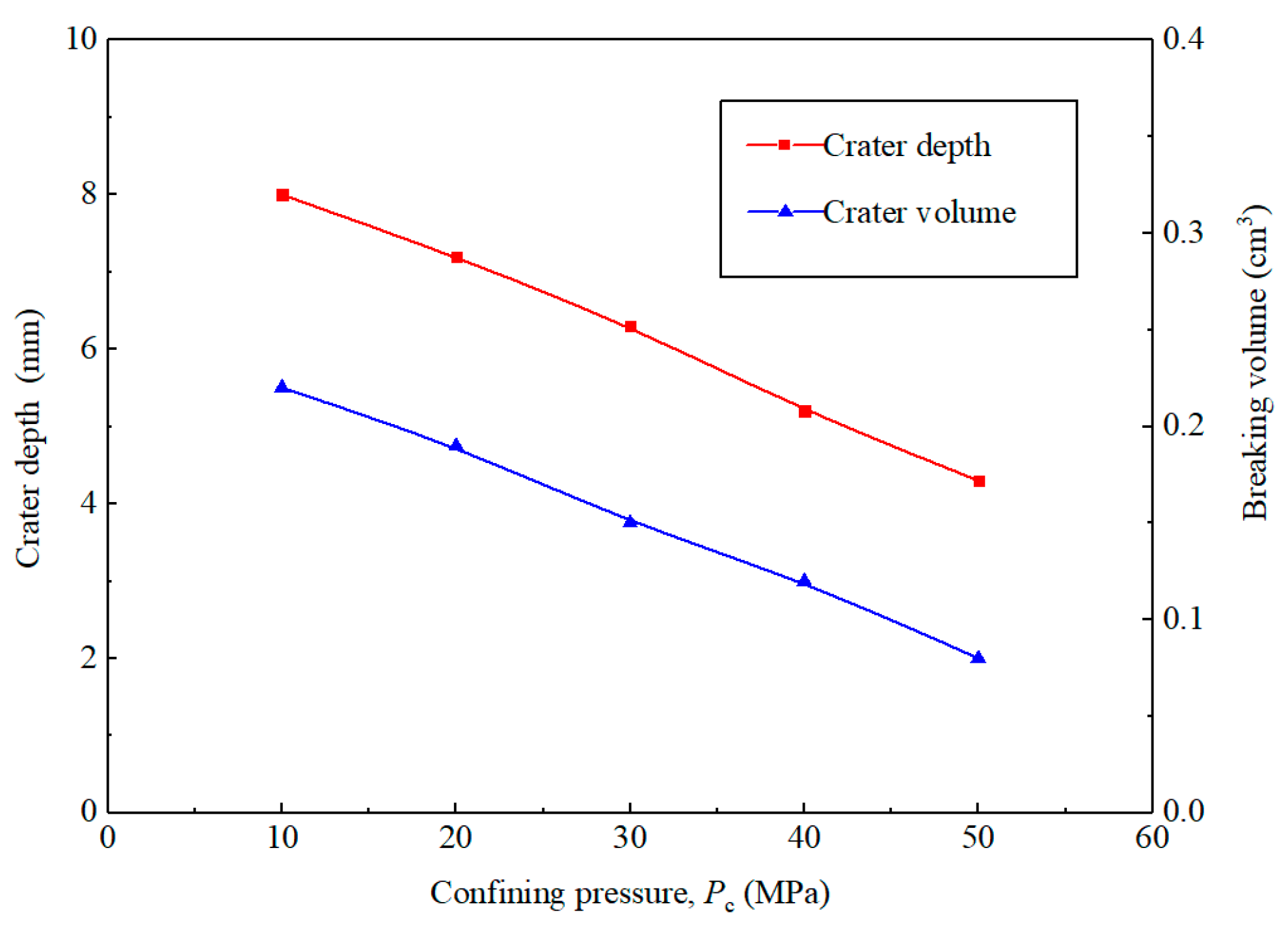
3.2.4. Confining Pressure
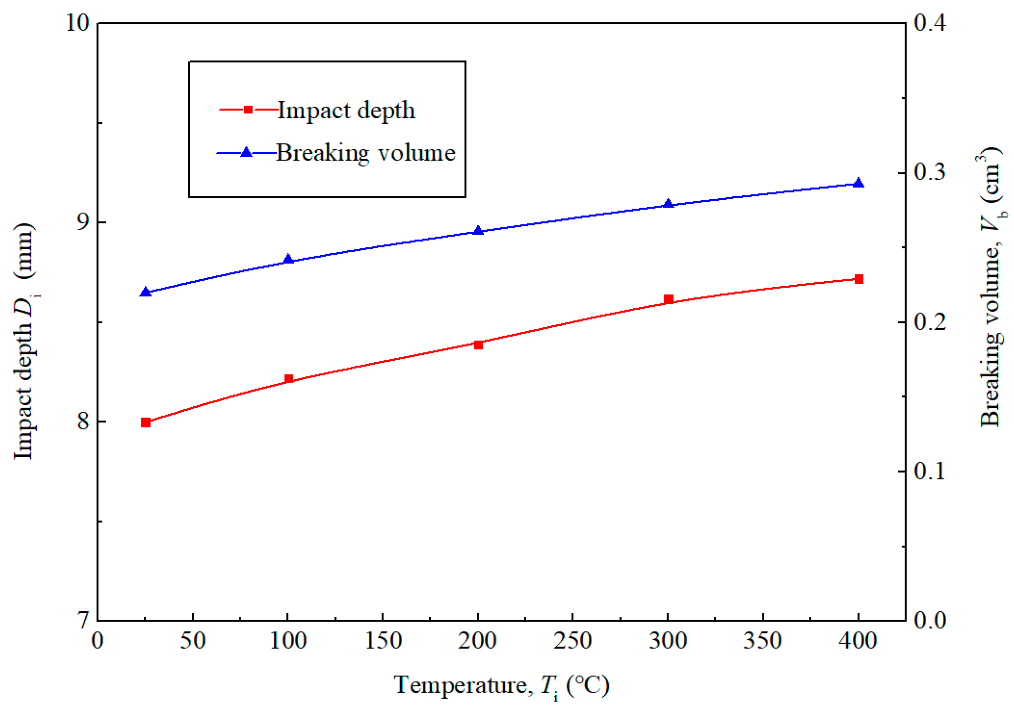
Figure 11 presents the relationship between impact crater depth and breaking volume as a function of confining pressure. Both depth and volume exhibit a decrease with increasing confining pressure. As the confining pressure varies from 10 to 50 MPa, the crater depth is decreased by 46.2%, while the crater volume is decreased by 63.6%. This is attributable to the enhanced tensile strength of rock under high confining pressure conditions, which impedes the development of damage within the rock [43]. Additionally, a portion of the particle impact energy propagates through the rock as stress waves, inducing tensile effects. High confining pressure influences both the peak value and frequency of these stress waves and thereby diminishes their damage effect on the rock and prolongs the time required for damage and breakage to occur. Consequently, increasing confining pressure leads to a reduction in both crater depth and volume.

3.2.5. Temperature

Figure 12 illustrates the relationship between impact crater depth and volume as a function of temperature. Both depth and volume demonstrate an increment with rising temperature. As the temperature varies from 25 to 400 °C, the crater depth is increased by 9%, while the crater volume is increased by 33.2%. This phenomenon can be explained by the behavior of hard and brittle rocks, whose uniaxial compressive strength and fracture toughness decrease significantly with increasing temperature [44]. As the rock temperature increases, the impact of high-speed particles on the rock surface generates substantial impact stress [45]. Due to the reduced strength of the rock at elevated temperatures, the particle impact is more likely to induce tensile shear failure within the rock, which facilitates the initiation, propagation, and extension of cracks. Consequently, increasing the temperature leads to a continuous increase in both the depth and volume of the impact crater.

4. Conclusions

Establishing and validating the breaking characteristics and governing principles of particle jet impact on sandstone is of paramount importance and provides theoretical guidance for the application of this technology to enhance CO2 injection efficiency. This study investigated the impact and breakage of sandstone by a particle jet under various parameters, including velocity, diameter, concentration, confining pressure, and temperature. The key findings are summarized as follows:
The impact rebound of the particle jet significantly influences the size of the impact crater. The maximum first principal stress generated during particle jet impact on the rock reaches 18.9 MPa and is primarily concentrated on the surface of the “v”-shaped crater formed by the impact.
Both the depth and volume of the impact crater exhibit a continuous increase with increasing jet inlet velocity. This is attributable to the greater impact stress generated at the moment of particle–rock contact at higher velocities. Increasing particle diameter leads to a continuous increase in both the depth and volume of the impact crater. For particle diameters ranging from 0.5 to 1 mm, particle movement within the jet is relatively more irregular.
With the increase in particle concentration, the depth of the impact crater initially rises rapidly. However, once the particle concentration exceeds 3%, the depth of the impact crater increases at a slower rate. Confining pressure impedes the efficiency of particle impact rock breaking. Moreover, higher temperatures result in larger impact depths and breaking volumes.
Future research needs to focus on the following aspects: the conducting of more experimental testing and analysis of the particle impact rock-breaking technology [46,47]; the development of field application equipment for this technology; the carrying out of field tests to verify the effect of this technology; the relationship between the particle jet reaming effect and CO2 geological storage efficiency and its influence on the development of CCUS technology [48,49].

Author Contributions

Methodology, Y.W.; software, J.Z.; validation, Y.W. and J.Z.; writing, J.Z. All authors have read and agreed to the published version of the manuscript.

Funding

This research was funded by the National Natural Science Foundation of China, grant number 52204022; Natural Science Foundation of Shandong Province, grant number ZR2022ME152; National Key Research and Development Program of China, grant number 2021YFE0111400; Youth Innovation and Technology Support Program for Shandong Provincial Universities, grant number 2022KJ066; Science and Technology Plan of Dongying City, grant number 2021ZD49.

Institutional Review Board Statement

Not applicable.

Informed Consent Statement

Not applicable.

Data Availability Statement

The datasets used and/or analyzed during the current study are available on reasonable request from the corresponding author due to privacy.

Acknowledgments

The authors would like to thank each member of the team for their efforts.

Conflicts of Interest

Author Yi Wang was employed by the company SINOPEC Research Institute of Petroleum Engineering, Co., Ltd. The remaining authors declare that the research was conducted in the absence of any commercial or financial relationships that could be construed as a potential conflict of interest.

Nomenclature

Nomenclature
avolume correction-
Acharacteristic bonding strength parameter-
Bcharacteristic pressure hardening index-
Cstrain rate effect coefficient-
Cbnormalization constant-
C e mixing efficiency coefficient-
Cpparticle volume concentrations%
CMG u s u p curve interceptm/s
Ddamage ratio-
Einternal energy per unit volume-
Epelasticity modulus of particles
hSPH particle smooth length-
mggas mass flow ratekg/s
mpparticle mass flow ratekg/s
mwwater mass flow ratekg/s
Npressure hardening index-
Pcconfining pressureMPa
P w nozzle pressureMPa
P MG pressureMPa
P * dimensionless hydrostatic pressure-
S1, S2, and S3 u s u p curve slope coefficient-
v w jet inlet velocity m/s
Titemperature°C
Greek letters
γ 0 MIE-GRUNEISEN constant-
ε * strain rate with a dimension of 1-
ρ 0 densityg/cm3
ρ p particle densityg/cm3
σ * equivalent stress pressure-
υpPoisson’s ratio of particles
Ωsupport domain of the point x-

References

  1. Cui, Y.N.; Bai, J.J.; Liao, S.L.; Cao, S.J.; Liu, F.Z. Suggestions on the development of environmental monitoring technology of CO2 geological storage and leakage under the background of China’s “Double-Carbon” strategy. Atmosphere 2023, 14, 51. [Google Scholar] [CrossRef]
  2. Rui, J. Progress of CO2 sequestration technique application in oil and gas industry. Pet. Petrochem. Today 2022, 30, 34–37. [Google Scholar]
  3. Li, X.Y.; Gao, X.; Xie, J.J. Comparison and clarification of china and US CCUS technology development. Atmosphere 2022, 13, 2114. [Google Scholar] [CrossRef]
  4. Ban, F.S.; Xiao, L.Z.; Yuan, G.J.; Yang, C.L. Rapid solution mining technology for underground gas storage in salt caverns and case histories. Nat. Gas Ind. 2012, 32, 77–79. [Google Scholar]
  5. Momber, A.W.; Kovacevic, R. Deformation and fracture of rocks loaded with spherical indenters. Int. J. Fract. 2004, 125, 206–279. [Google Scholar] [CrossRef]
  6. Momber, A.W. A refined model for solid particle rock erosion. Rock Mech. Rock Eng. 2016, 49, 464–475. [Google Scholar] [CrossRef]
  7. Sahu, J.N.; Sasikumar, C. Room temperature Case Carburizing of a Ni–Cr–Mo Steel Through Shot Peening/Blasting Techniques. Trans. Indian Inst. Met. 2015, 68, 227–233. [Google Scholar] [CrossRef]
  8. Zhao, J.; Sun, B.J.; Chang, F.R.; Han, X.Q.; Ning, Q.; Xu, Y.J. Cement erosion process with recyclable sand particle water-jet impacts. J. Clean. Prod. 2021, 292, 126006. [Google Scholar] [CrossRef]
  9. Szesz, E.M.; Pereira, B.L.; Kuromoto, N.K. Electrochemical and morphological analyses on the titanium surface modified by shot blasting and anodic oxidation processe. Thin Solid Film. 2013, 528, 163–166. [Google Scholar] [CrossRef]
  10. Tibbtitts, G.A.; Galloway, G.G. Particle drilling alters standard rock-cutting approach. World Oil 2008, 229, 37–44. [Google Scholar]
  11. Tibbtitts, G.A.; Galloway, G.G.; Terry, J.B. Impactor Excavation System Having a Drill Bit Discharging in a Cross over Pattern. U.S. Patent 8845279B2, 16 July 2013. [Google Scholar]
  12. Galloway, G.G. Shot Blocking Using Drilling Mud. U.S. Patent 8342256B2, 1 January 2013. [Google Scholar]
  13. Zhao, J.; Zhang, G.C.; Xu, Y.J.; Wang, R.H.; Zhou, W.D. Mechanism and effect of jet parameters on particle waterjet rock breaking. Powder Technol. 2017, 313, 231–244. [Google Scholar] [CrossRef]
  14. Momber, A.W. Wear of rocks by water flow. Int. J. Rock Mech. Min. 2004, 41, 51–68. [Google Scholar] [CrossRef]
  15. Ren, F.S.; Fang, T.C.; Cheng, X.Z.; Cheng, J.X. Failure volume under particle water-jet impact in deep well drilling engineering: Mathematical modeling and verification analysis. Alex. Eng. J. 2021, 60, 1839–1849. [Google Scholar] [CrossRef]
  16. Zeng, J.; Kim, T.J. A erosion model of polycrystalline ceramics in abrasive waterjet cutting. Wear 1996, 193, 207–217. [Google Scholar] [CrossRef]
  17. Li, G.S.; Huang, Z.W.; Niu, J.L. The productivity-enhancing technique of deep penetrating perforation with a high-pressure water jet. Pet. Sci. Technol. 2007, 25, 289–297. [Google Scholar]
  18. Xu, Y.Q.; Li, F.X.; Li, Q.D. Numerical simulation method and structural optimization for shearing capacity of ram blowout preventers. Geoenergy Sci. Eng. 2024, 233, 212559. [Google Scholar] [CrossRef]
  19. Huang, C.K.; Chinvelli, S.; Minev, P. A comprehensive phenomenological model for erosion of materials in jet flow. Powder Technol. 2008, 187, 273–279. [Google Scholar] [CrossRef]
  20. Finnie, I. Erosion of surfaces by solid particles. Wear 1960, 3, 87–103. [Google Scholar] [CrossRef]
  21. Xu, Y.Q.; Wang, Y.C.; Tian, Y. Experimental study on ultrasonic wave propagation characteristics of gas-liquid two-phase flow in riser annulus. Appl. Ocean Res. 2023, 141, 103771. [Google Scholar]
  22. Tae-Min, O.; Gye-Chun, C. Characterization of effective parameters in abrasive water jet rock cutting. Rock Mech. Rock Eng. 2014, 47, 745–756. [Google Scholar]
  23. Petrica, M.; Badisch, E.; Peinsitt, T. Abrasive wear mechanisms and their relation to rock properties. Wear 2013, 308, 86–94. [Google Scholar] [CrossRef]
  24. Momber, A.W. Effects of target material properties on solid particle erosion of geomaterials at different impingement velocities. Wear 2015, 319, 69–83. [Google Scholar] [CrossRef]
  25. Momber, A.W. Erosion of schist due to solid particle impingement. Rock Mech. Rock Eng. 2013, 46, 849–857. [Google Scholar] [CrossRef]
  26. Peng, C.; Tian, S.C.; Li, G.S.; Sukop, M.C. Simulation of laser-produced single cavitation bubbles with hybrid thermal Lattice Boltzmann method. Int. J. Heat Mass Transf. 2020, 149, 119136. [Google Scholar] [CrossRef]
  27. Lausch, M.; Reitter, L.M.; Schremb, M.; Hussong, J. Impact of an ice particle onto a rigid substrate: Statistical analysis of the fragment size distribution. Int. J. Impact Eng. 2023, 181, 104732. [Google Scholar] [CrossRef]
  28. Sun, H.F.; Huang, L.; Long, J.B.; Ruan, F. CFD-DEM coupled calculation of wall wear characteristics during particles flow impacting the wall process. Powder Tech. 2023, 426, 118684. [Google Scholar] [CrossRef]
  29. Han, S.P.; Sun, Z.W.; Tian, Z.F.; Chinnici, A.; Lau, T.; Troiano, M.; Solimene, R.; Salatino, P.; Nathan, G.J. Experimental study of a dense stream of particles impacting on an inclined surface. Powder Tech. 2024, 438, 119658. [Google Scholar] [CrossRef]
  30. Zhou, Y.; Lv, W.J.; Zhang, C.; Zhou, Z.H.; Wang, H.Y.; Liang, Q.Y.; Tang, Q.Q.; Han, G.S.; Guo, W.; Zhao, D.J. Novel hard rock breaking technique using ultra-high-frequency particle impact induced by ultrasonic vibration field. Energy 2024, 288, 129747. [Google Scholar] [CrossRef]
  31. Song, G.Y.; Hogan, C.J. Crystal grain size effects and crystallinity dynamics during supersonic particle impacts. Int. J. Plast. 2023, 170, 103758. [Google Scholar] [CrossRef]
  32. Peng, D.; Wang, L.G.; Lin, Y.Q.; Zhu, C.Q.; Chen, X.Z.; Liu, Z.H.; Ge, R.H. Oblique impact breakage unification of nonspherical particles using discrete element method. Particuology 2024, 90, 61–71. [Google Scholar] [CrossRef]
  33. Hadavi, V.; Papini, M. Numerical modeling of particle embedment during solid particle erosion of ductile materials. Wear 2015, 342, 310–321. [Google Scholar] [CrossRef]
  34. Goodin, C.; Priddy, J.D. Comparison of SPH simulations and cone index tests for cohesive soils. J. Terra. Mech. 2016, 66, 49–57. [Google Scholar] [CrossRef]
  35. Aktay, L.; Johnson, A.F.; Toksoy, A.K. Modeling the progressive axial crushing of foam-filled aluminum tubes using smooth particle hydrodynamics and coupled finite element model/smooth particle hydrodynamics. Mater. Design 2008, 29, 569–575. [Google Scholar] [CrossRef]
  36. Zhao, J.; Liao, H.L.; Xu, Y.J.; Shi, F.X.; Sun, B.J.; Chang, F.R.; Han, X.Q. Experimental and theoretical evaluation of tubing cutting with rotating particle jet in oil and gas borehole operation. Energy 2023, 282, 128468. [Google Scholar] [CrossRef]
  37. Bielawski, M.; Beres, W. FE modelling of surface stresses in erosion-resistant coatings under single particle impact. Wear 2007, 262, 167–175. [Google Scholar] [CrossRef]
  38. Sun, Z.H. Dynamics Response Analysis of Penetration Based on FE-SPH Adaptive Coupling Method; The Hunan University Press: Changsha, China, 2012. [Google Scholar]
  39. Lin, X.D.; Lu, Y.Y.; Tang, J.R. Numerical simulation of abrasive water jet breaking rock with SPH-FEM coupling algorithm. J. Vib. Shock 2014, 33, 170–175. [Google Scholar]
  40. Kong, X.Z.; Fang, Q.; Wu, H. Numerical predictions of cratering and scabbing in concrete slabs subjected to projectile impact using a modified version of HJC material model. Int. J. Impact Eng. 2016, 95, 61–71. [Google Scholar] [CrossRef]
  41. Lu, B.; Wu, X.T. Finite element simulation of sandstone SHPB experiment under impact load. J. Hefei Univ. Tech. 2022, 45, 1517–1521. [Google Scholar]
  42. Papini, M.; Ciampini, D.; Krajac, T. Computer modelling of interference effects in erosion testing: Effect of plume shape. Wear 2003, 255, 85–97. [Google Scholar] [CrossRef]
  43. Shen, Y.F.; Xu, S.; Feng, P.Y.; Pang, F.L. Numerical simulation of rock damage mechanism by water jet under confining pressure. Saf. Coal Mines 2022, 53, 59–65. [Google Scholar]
  44. Song, J.C.; Wang, Z.J.; Li, Y. Research on granite cutting and breaking test under conditions of high temperature and high pressure. Chi. J. Rock Mech. Eng. 2009, 28, 1422–1438. [Google Scholar]
  45. Chen, C.J.; Zhu, Y.; Li, Z.P.; Zhang, H.D.; Liu, Y. Energy criterion of coal breaking by abrasive jets based on stress wave effect. J. China Coal Soc. 2022, 47, 3320–3327. [Google Scholar]
  46. Huppert, H.E.; Neufeld, J.A. The fluid mechanics of carbon dioxide sequestration. Annu. Rev. Med. 2014, 46, 255–272. [Google Scholar] [CrossRef]
  47. Munkejord, S.T.; Bernstone, C.; Clausen, S.; Koeijer, G.D.; Mølnvik, M.J. Combining thermodynamic and fluid flow modelling for CO2 flow assurance. Energy Procedia 2013, 37, 2904–2913. [Google Scholar] [CrossRef]
  48. Labzovskii, L.D.; Mak, H.W.L.; Kenea, S.T.; Rhee, J.S.; Lashkari, A.; Li, S.L.; Goo, T.Y.; Oh, Y.S.; Byun, Y.H. What can we learn about effectiveness of carbon reduction policies from interannual variability of fossil fuel CO2 emissions in East Asia? Environ. Sci. Policy 2019, 96, 132–140. [Google Scholar] [CrossRef]
  49. Sohn, B.J.; Yeh, S.W.; Lee, A.; Lau, W.K.M. Regulation of atmospheric circulation controlling the tropical Pacific precipitation change in response to CO2 increases. Nat. Commun. 2019, 10, 1108. [Google Scholar] [CrossRef]
Figure 1. Finite element model for rock breaking under particle jet impact.
Atmosphere 15 00645 g001
Figure 2. Experimental flow chart and setup.
Atmosphere 15 00645 g002
Figure 3. Experimental material: (a) steel particles, (b) rock sample.
Atmosphere 15 00645 g003
Figure 4. Rock-breaking process under particle jet impact. (a) t = 0 s; (b) t = 0.04 s; (c) t = 0.08 s; (d) t = 0.12 s.
Atmosphere 15 00645 g004aAtmosphere 15 00645 g004b
Figure 5. Temporal evolution of the first principal stress within the rock. (a) t = 0 s; (b) t = 0.04 s; (c) t = 0.08 s; (d) t = 0.12 s.
Atmosphere 15 00645 g005
Figure 6. Crater morphology resulting from particle jet impact: (a) SPH simulation; (b) experiment.
Atmosphere 15 00645 g006
Figure 7. Influence of jet inlet velocity on impact crater depth and volume.
Atmosphere 15 00645 g007
Figure 8. Impact of particle diameter on the depth and volume of the impact crater.
Atmosphere 15 00645 g008
Figure 9. Influence of particle concentration on impact crater depth and volume.
Atmosphere 15 00645 g009
Figure 10. Inter-particle interference collision effect.
Atmosphere 15 00645 g010
Figure 11. Influence of confining pressure on impact crater depth and volume.
Atmosphere 15 00645 g011
Figure 12. Influence of temperature on impact crater depth and volume.
Atmosphere 15 00645 g012
Table 1. 1# elastic material model parameters for particles [31].
Material ρ p [g/cm3] υ p Ep [GPa]
Particle78000.3210
Table 2. Water parameters for simulation [39].
Material ρ 0 [g/cm3]C [m/s] S 1 S 2 S 3 a γ 0
Water114802.56−1.9860.22861.3970.49
Table 3. HJC model parameters for the rock during simulation [41].
ρ [kg/m3]G [GPa] f C [MPa]ABCN S MAX D 1 D 2
23416.347.90.791.400.0070.517.00.041.0
ε fmin T [MPa] p c [MPa] μ c p 1 [GPa] μ 1 k 1 [MPa] k 2 [MPa] k 3 [MPa] ε 0
0.014.3160.00190.810.185−1712101
Table 4. The deviations between the simulation results and experimental results.
ParametersExperimentSimulationDeviation
Crater depth [mm]5.55.73.6%
Crater volume [cm3]0.2400.2525%
Disclaimer/Publisher’s Note: The statements, opinions and data contained in all publications are solely those of the individual author(s) and contributor(s) and not of MDPI and/or the editor(s). MDPI and/or the editor(s) disclaim responsibility for any injury to people or property resulting from any ideas, methods, instructions or products referred to in the content.

